Embed Size (px)
Citation preview
CFIP Series
Full Outdoor Unit
Technical Description & Configuration Guide
Product code: I0DFAED1
SAF Tehnika JSC 2011
The CFIP Series Full Outdoor Unit Technical Description and Configuration Guide • Rev. 1.7 •
© SAF Tehnika JSC 2011
2
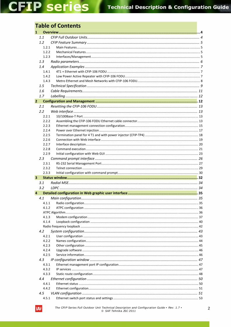
Table of Contents 1 Overview ....................................................................................................................................... 4 1.1 CFIP Full Outdoor Units................................................................................................................... 4 1.2 CFIP Feature Summary ................................................................................................................... 5
1.2.1 Main Features ........................................................................................................................................... 5 1.2.2 Mechanical Features ................................................................................................................................. 5 1.2.3 Interfaces/Management ........................................................................................................................... 5
1.3 Radio parameters ........................................................................................................................... 6 1.4 Application Examples ..................................................................................................................... 7
1.4.1 4T1 + Ethernet with CFIP‐106 FODU ......................................................................................................... 7 1.4.2 Low Power Active Repeater with CFIP‐106 FODU..................................................................................... 7 1.4.3 Metro Ethernet and Mesh Networks with CFIP‐106 FODU....................................................................... 8
1.5 Technical Specification ................................................................................................................... 9 1.6 Cable Requirements ...................................................................................................................... 11 1.7 Labelling ....................................................................................................................................... 12
2 Configuration and Management .................................................................................................. 12 2.1 Resetting the CFIP‐106 FODU ....................................................................................................... 13 2.2 Web interface ............................................................................................................................... 13
2.2.1 10/100Base‐T Port .................................................................................................................................. 13 2.2.2 Assembling the CFIP‐106 FODU Ethernet cable connector ..................................................................... 13 2.2.3 Ethernet management connection configuration ................................................................................... 15 2.2.4 Power over Ethernet injection ................................................................................................................ 17 2.2.5 Termination panel for 4 T1 and with power injector (CFIP‐TP4) ............................................................ 18 2.2.6 Connection with Web interface .............................................................................................................. 19 2.2.7 Interface description ............................................................................................................................... 20 2.2.8 Command execution ............................................................................................................................... 21 2.2.9 Initial configuration with Web GUI ......................................................................................................... 23
2.3 Command prompt interface ......................................................................................................... 26 2.3.1 RS‐232 Serial Management Port ............................................................................................................. 27 2.3.2 Telnet connection ................................................................................................................................... 29 2.3.3 Initial configuration with command prompt ........................................................................................... 30
3 Status window ............................................................................................................................. 32 3.1 Radial MSE.................................................................................................................................... 34 3.2 LDPC ............................................................................................................................................. 34
4 Detailed configuration in Web graphic user interface ................................................................... 35 4.1 Main configuration ....................................................................................................................... 35
4.1.1 Radio configuration ................................................................................................................................. 35 4.1.2 ATPC configuration ................................................................................................................................. 36 ATPC Algorithm ...................................................................................................................................................... 36 4.1.3 Modem configuration ............................................................................................................................. 37 4.1.4 Loopback configuration .......................................................................................................................... 40 Radio frequency loopback ..................................................................................................................................... 42
4.2 System configuration .................................................................................................................... 43 4.2.1 User configuration .................................................................................................................................. 43 4.2.2 Names configuration ............................................................................................................................... 44 4.2.3 Other configuration ................................................................................................................................ 45 4.2.4 Upgrade software ................................................................................................................................... 46 4.2.5 Service information ................................................................................................................................. 46
4.3 IP configuration window .............................................................................................................. 47 4.3.1 Ethernet management port IP configuration .......................................................................................... 47 4.3.2 IP services ............................................................................................................................................... 47 4.3.3 Static route configuration ....................................................................................................................... 48
4.4 Ethernet configuration ................................................................................................................. 50 4.4.1 Ethernet status ....................................................................................................................................... 50 4.4.2 Ethernet configuration ............................................................................................................................ 51
4.5 VLAN configuration ...................................................................................................................... 51 4.5.1 Ethernet switch port status and settings ................................................................................................ 53
The CFIP Series Full Outdoor Unit Technical Description and Configuration Guide • Rev. 1.7 •
© SAF Tehnika JSC 2011
3
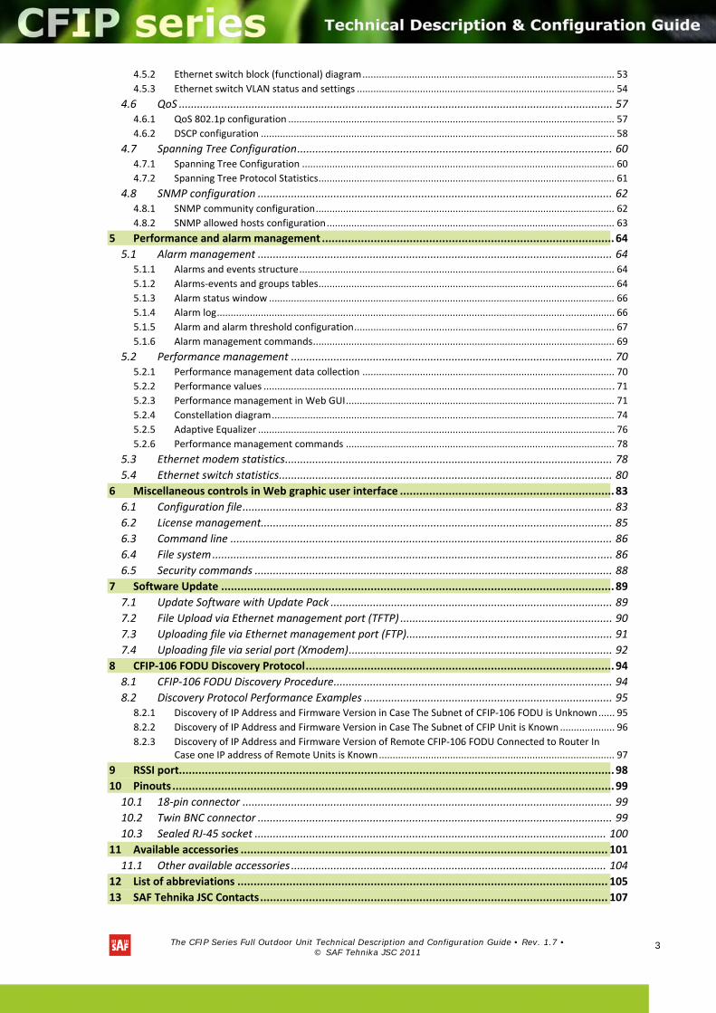
4.5.2 Ethernet switch block (functional) diagram ............................................................................................ 53 4.5.3 Ethernet switch VLAN status and settings .............................................................................................. 54
4.6 QoS ............................................................................................................................................... 57 4.6.1 QoS 802.1p configuration ....................................................................................................................... 57 4.6.2 DSCP configuration ................................................................................................................................. 58
4.7 Spanning Tree Configuration ........................................................................................................ 60 4.7.1 Spanning Tree Configuration .................................................................................................................. 60 4.7.2 Spanning Tree Protocol Statistics ............................................................................................................ 61
4.8 SNMP configuration ..................................................................................................................... 62 4.8.1 SNMP community configuration ............................................................................................................. 62 4.8.2 SNMP allowed hosts configuration ......................................................................................................... 63
5 Performance and alarm management .......................................................................................... 64 5.1 Alarm management ..................................................................................................................... 64
5.1.1 Alarms and events structure ................................................................................................................... 64 5.1.2 Alarms‐events and groups tables ............................................................................................................ 64 5.1.3 Alarm status window .............................................................................................................................. 66 5.1.4 Alarm log ................................................................................................................................................. 66 5.1.5 Alarm and alarm threshold configuration ............................................................................................... 67 5.1.6 Alarm management commands .............................................................................................................. 69
5.2 Performance management .......................................................................................................... 70 5.2.1 Performance management data collection ............................................................................................ 70 5.2.2 Performance values ................................................................................................................................ 71 5.2.3 Performance management in Web GUI .................................................................................................. 71 5.2.4 Constellation diagram ............................................................................................................................. 74 5.2.5 Adaptive Equalizer .................................................................................................................................. 76 5.2.6 Performance management commands .................................................................................................. 78
5.3 Ethernet modem statistics ............................................................................................................ 78 5.4 Ethernet switch statistics .............................................................................................................. 80
6 Miscellaneous controls in Web graphic user interface .................................................................. 83 6.1 Configuration file .......................................................................................................................... 83 6.2 License management.................................................................................................................... 85 6.3 Command line .............................................................................................................................. 86 6.4 File system .................................................................................................................................... 86 6.5 Security commands ...................................................................................................................... 88
7 Software Update ......................................................................................................................... 89 7.1 Update Software with Update Pack ............................................................................................. 89 7.2 File Upload via Ethernet management port (TFTP) ...................................................................... 90 7.3 Uploading file via Ethernet management port (FTP) .................................................................... 91 7.4 Uploading file via serial port (Xmodem) ....................................................................................... 92
8 CFIP‐106 FODU Discovery Protocol ............................................................................................... 94 8.1 CFIP‐106 FODU Discovery Procedure ............................................................................................ 94 8.2 Discovery Protocol Performance Examples .................................................................................. 95
8.2.1 Discovery of IP Address and Firmware Version in Case The Subnet of CFIP‐106 FODU is Unknown ...... 95 8.2.2 Discovery of IP Address and Firmware Version in Case The Subnet of CFIP Unit is Known .................... 96 8.2.3 Discovery of IP Address and Firmware Version of Remote CFIP‐106 FODU Connected to Router In
Case one IP address of Remote Units is Known ...................................................................................... 97 9 RSSI port...................................................................................................................................... 98 10 Pinouts ........................................................................................................................................ 99 10.1 18‐pin connector .......................................................................................................................... 99 10.2 Twin BNC connector ..................................................................................................................... 99 10.3 Sealed RJ‐45 socket .................................................................................................................... 100
11 Available accessories ................................................................................................................. 101 11.1 Other available accessories ........................................................................................................ 104
12 List of abbreviations .................................................................................................................. 105 13 SAF Tehnika JSC Contacts ........................................................................................................... 107
The CFIP Series Full Outdoor Unit Technical Description and Configuration Guide • Rev. 1.7 •
© SAF Tehnika JSC 2011
4
Proprietary notice
The information presented in this guide is the property of SAF Tehnika, JSC. No part of this document may be reproduced or transmitted without proper permission from SAF Tehnika, JSC.
The specifications or information contained in this document are subject to change without notice due to continuing introduction of design improvements. If there is any conflict between this document and compliance statements, the latter will supersede this document.
SAF Tehnika, JSC has no liability for typing errors in this document or damages of any kind that result from the use of this document.
To get up to date information about accessories and their availability, please contact sales representative.
Note: FODU/ODU does not contain serviceable parts. Warranty will not be applicable in the event FODU/ODU has been hermetically unsealed.
Note: SAF Tehnika, JSC is not responsible for any radio or TV interference caused by unauthorized modifications to this equipment. Such modifications could void the user's authority to operate the equipment.
Copyright Notice
Copyright © 2011 SAF Tehnika, JSC. All rights reserved.
1 Overview
This document briefly describes the CFIP series Full Outdoor Unit (FODU) covering the built‐in management system, configuration functionality, hardware features, etc.
1.1 CFIP Full Outdoor Units
CFIP product family is the new next generation product line which is targeting on growing demands for data transmission over microwave radio.
As a result the primary traffic interface for CFIP radio is Fast Ethernet. In addition, CFIP is capable of delivering up to 4T1 interfaces for legacy connectivity or any other use. As CFIP is capable of providing bit rate of up to 106 Mbps to all interfaces combined, it is a great addition to SAF portfolio. This product family provides perfect solution for a user looking for higher capacity than PDH T3 without need for STM‐1 capacity. CFIP radio and modem performance allows to achieve perfect system capacity by employing 128‐level modulation scheme by user’s choice. Apart from the full system capacity of 106 Mbps, it is possible to configure the radio to any of 10, 20 and 30 MHz channels as well as to any of QPSK, 16APSK, 32APSK, 64QAM and 128QAM modulations, thus providing various capacities to suit particular needs.
SAF Tehnika has employed most modern design solutions and components to create high performance compact radio with low power consumption – 19‐35W (low power) and 19‐43W (high power) per radio, thus we have a capability to feed the unit by using Power over Ethernet (at least 50W) means.
CFIP is a perfect building block for any modern future proof wireless network, including mobile service providers, fixed data service operators, enterprise customers, municipal and governmental networks among others.
The CFIP Series Full Outdoor Unit Technical Description and Configuration Guide • Rev. 1.7 •
© SAF Tehnika JSC 2011
5
1.2 CFIP Feature Summary
1.2.1 Main Features
• Full Outdoor solution
• Capacity: up to 106 Mbps
• Channel Bandwidth: 10/20/30 MHz
• Modulations: QPSK, 16APSK, 32APSK, 64QAM, 128QAM
• Interfaces: 10/100Eth+4T1
• Traffic: Ethernet only, Eth+1T1 to Eth+4T1
• Frequency bands: 6 / 11 / 18 / 23 / 24UL / 38 GHz
• Power over Ethernet
• Green Radio – 19‐35W (low power) and 19‐43W (high power) of power consumption
• ACM and ATPC with QoS four priority queues
• 802.1Q VLAN support
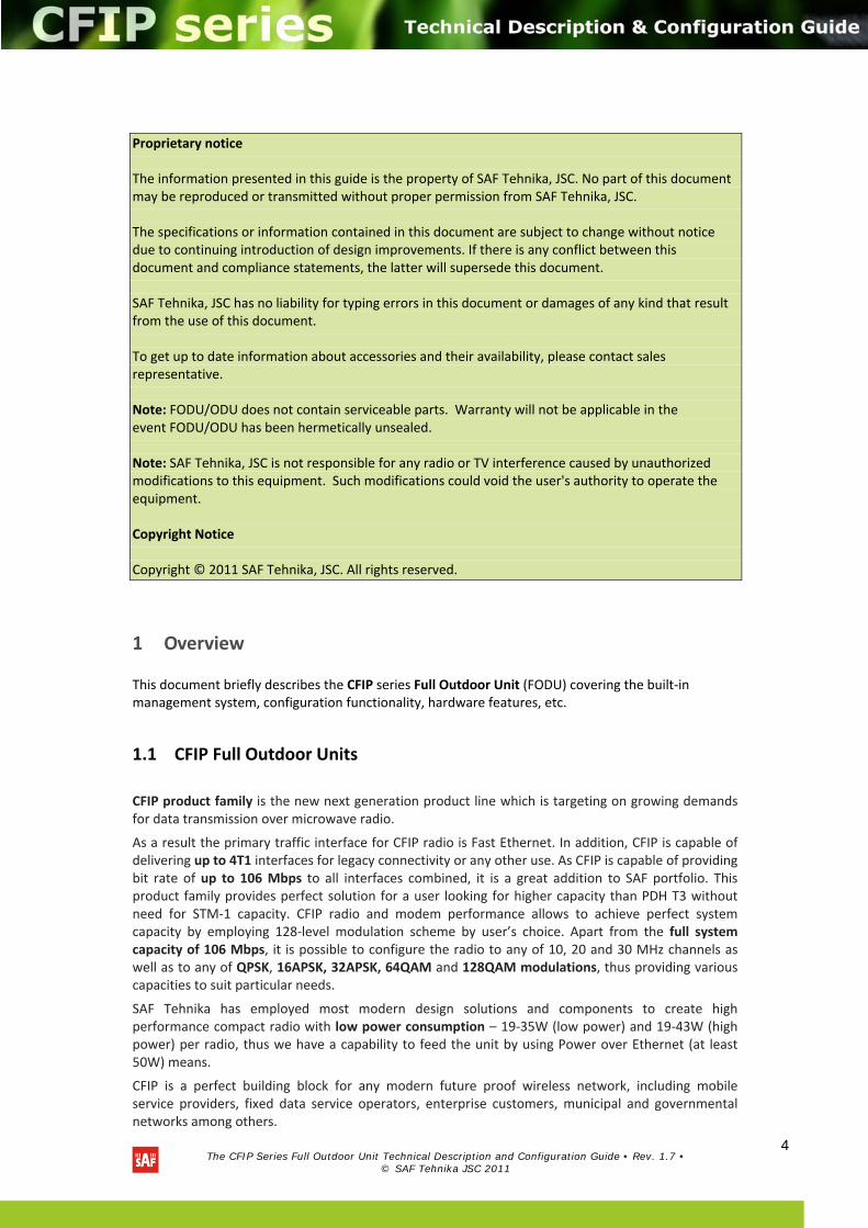
1.2.2 Mechanical Features
• Compact unit, 11.2x11.2x3.1in, 7.7 lbs, antenna adaption backwards compatible with all CFM and CFQ series units
• 3 handles for user convenience
• Safe and easy to use 4 side locking arrangement
• All connectors on the side of the unit, always at 45° regarding vertical axis for both V and H polarization
Figure 1.1: CFIP‐106 Full Outdoor Unit
1.2.3 Interfaces/Management
• CFIP‐106 FODU unit provides 4 connectors and a grounding screw
The CFIP Series Full Outdoor Unit Technical Description and Configuration Guide • Rev. 1.7 •
© SAF Tehnika JSC 2011
6
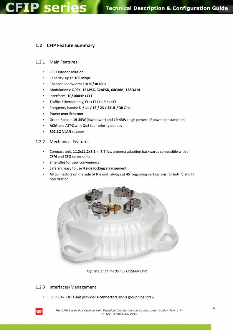
• User, NMS traffic and DC power are fed over Cat. 5e or above cable and weather protected RJ‐45 connector
• Ethernet traffic supports QoS and 4 priority queues, essential for ACM use
• User and NMS traffic could be treated as a single data stream or separated by tagging with different VLAN tags
• 4 ports of balanced T1 interfaces are provided over weather protected 18pin connector
• Twin BNC connector of the unit enables terminal access into the unit
• BNC connector provides RSSI voltage signal to assist unit alignment
• Web, Telnet and SNMP are available as NMS interfaces into the unit
Figure 1.2: CFIP‐106 FODU connectors
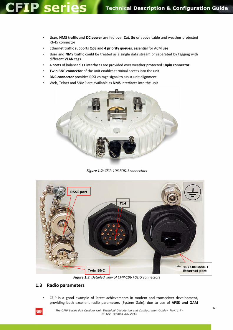
Figure 1.3: Detailed view of CFIP‐106 FODU connectors
1.3 Radio parameters
• CFIP is a good example of latest achievements in modem and transceiver development, providing both excellent radio parameters (System Gain), due to use of APSK and QAM
10/100Base-T Ethernet port
T14
RSSI port
Twin BNC
The CFIP Series Full Outdoor Unit Technical Description and Configuration Guide • Rev. 1.7 •
© SAF Tehnika JSC 2011
7
modulations and efficient despite it consumes small amount of power power Tx/Rx part of the system.
• RSL Threshold at BER 10‐6, 30MHz, 32APSK, 100Mbps: ‐75 dBm.
• System Gain with guaranteed max Tx power and Rx sensitivity is 92 dB.
• ACM (Adaptive Coding and Modulation), hitless ACM opens whole lot of new possibilities depending on network designers strategy
• ATPC, Automatic Transmitter Power Control, for increased deployment density capability.
• Very high flexibility allows configuring the system to various channel bandwidths, modulation schemes and capacity settings
1.4 Application Examples
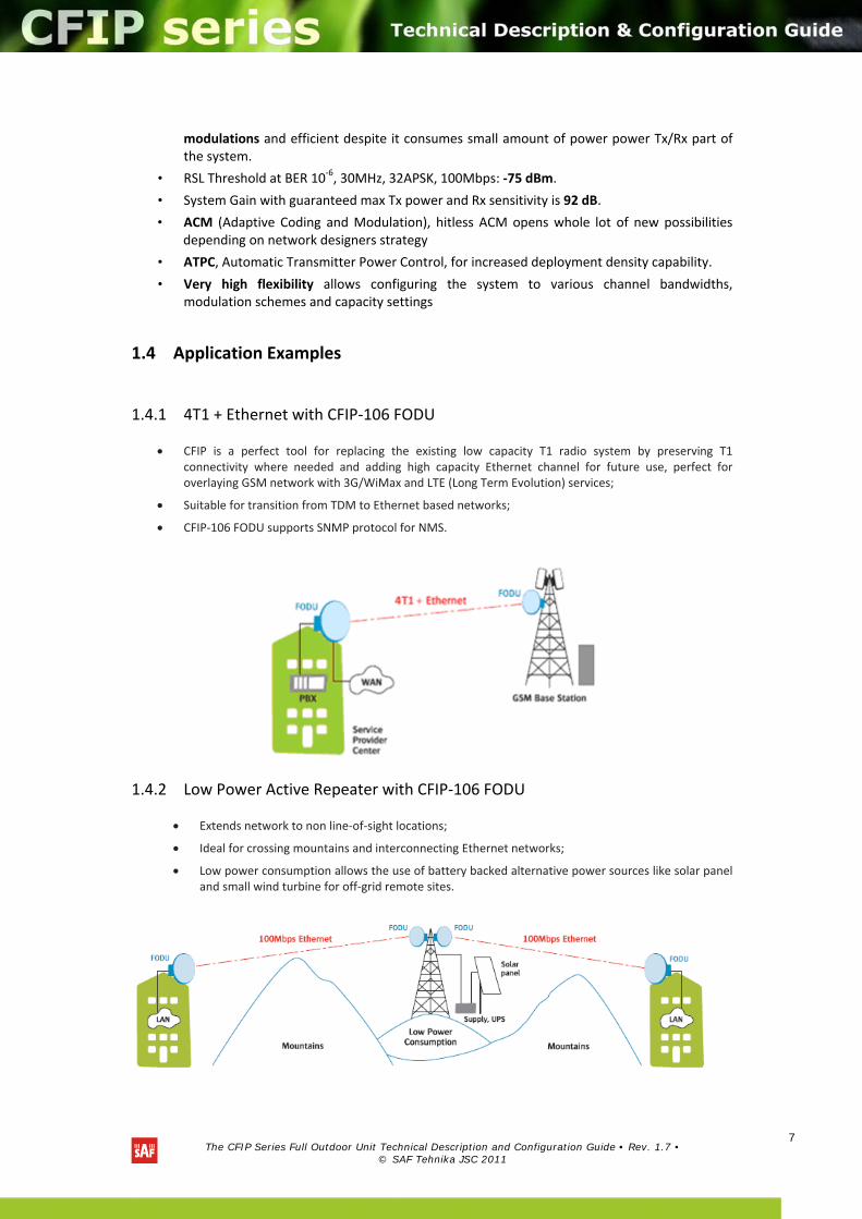
1.4.1 4T1 + Ethernet with CFIP‐106 FODU
CFIP is a perfect tool for replacing the existing low capacity T1 radio system by preserving T1 connectivity where needed and adding high capacity Ethernet channel for future use, perfect for overlaying GSM network with 3G/WiMax and LTE (Long Term Evolution) services;
Suitable for transition from TDM to Ethernet based networks;
CFIP‐106 FODU supports SNMP protocol for NMS.
1.4.2 Low Power Active Repeater with CFIP‐106 FODU
Extends network to non line‐of‐sight locations;
Ideal for crossing mountains and interconnecting Ethernet networks;
Low power consumption allows the use of battery backed alternative power sources like solar panel and small wind turbine for off‐grid remote sites.
The CFIP Series Full Outdoor Unit Technical Description and Configuration Guide • Rev. 1.7 •
© SAF Tehnika JSC 2011
8
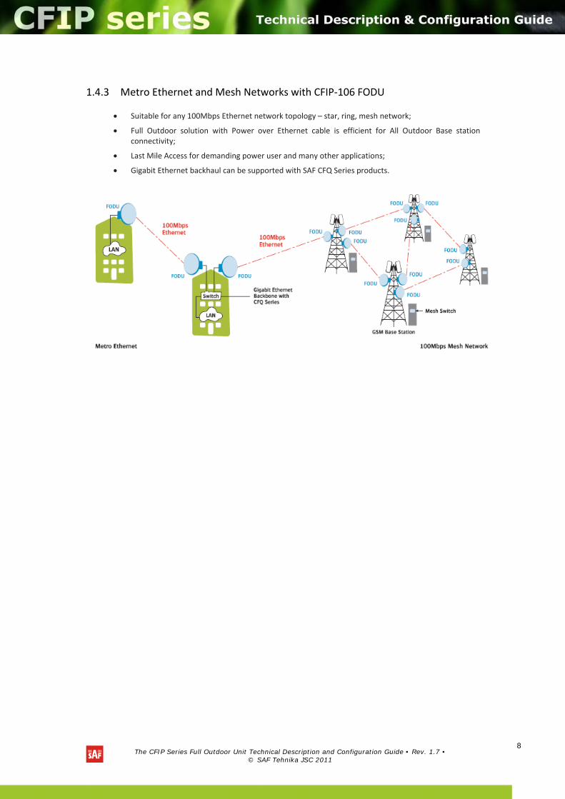
1.4.3 Metro Ethernet and Mesh Networks with CFIP‐106 FODU
Suitable for any 100Mbps Ethernet network topology – star, ring, mesh network;
Full Outdoor solution with Power over Ethernet cable is efficient for All Outdoor Base station connectivity;
Last Mile Access for demanding power user and many other applications;
Gigabit Ethernet backhaul can be supported with SAF CFQ Series products.
The CFIP Series Full Outdoor Unit Technical Description and Configuration Guide • Rev. 1.7 •
© SAF Tehnika JSC 2011
9
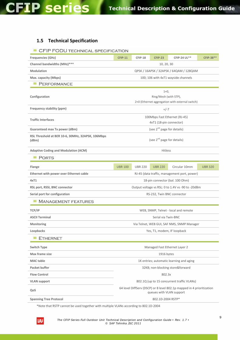
1.5 Technical Specification
*Note that RSTP cannot be used together with multiple VLANs according to 802.1D‐2004
Frequencies (GHz) CFIP‐11 CFIP‐18 CFIP‐23 CFIP‐24 UL** CFIP‐38**
Channel bandwidths (MHz)*** 10, 20, 30
Modulation QPSK / 16APSK / 32APSK / 64QAM / 128QAM
Max. capacity (Mbps) 100; 106 with 4xT1 wayside channels
Configuration
1+0,
Ring/Mesh (with STP),
2+0 (Ethernet aggregation with external switch)
Frequency stability (ppm)
+/‐7
Traffic Interfaces 100Mbps Fast Ethernet (RJ‐45)
4xT1 (18‐pin connector)
Guaranteed max Tx power (dBm) (see 2nd page for details)
RSL Threshold at BER 10‐6, 30MHz, 32APSK, 106Mbps (dBm)
(see 2nd page for details)
Adaptive Coding and Modulation (ACM) Hitless
Flange UBR 100 UBR 220 UBR 220 Circular 10mm UBR 320
Ethernet with power over Ethernet cable RJ‐45 (data traffic, management port, power)
4xT1 18‐pin connector (bal. 100 Ohm)
RSL port, RSSI, BNC connector Output voltage vs RSL: 0 to 1.4V vs ‐90 to ‐20dBm
Serial port for configuration RS‐232, Twin BNC connector
TCP/IP WEB, SNMP, Telnet ‐ local and remote
ASCII Terminal Serial via Twin‐BNC
Monitoring Via Telnet, WEB GUI, SAF NMS, SNMP Manager
Loopbacks Yes, T1, modem, IF loopback
Switch Type Managed Fast Ethernet Layer 2
Max frame size 1916 bytes
MAC table 1K entries; automatic learning and aging
Packet buffer 32KB; non‐blocking store&forward
Flow Control 802.3x
VLAN support 802.1Q (up to 15 concurrent traffic VLANs)
QoS 64 level DiffServ (DSCP) or 8 level 802.1p mapped in 4 prioritization
queues with VLAN support
Spanning Tree Protocol 802.1D‐2004 RSTP*
The CFIP Series Full Outdoor Unit Technical Description and Configuration Guide • Rev. 1.7 •
© SAF Tehnika JSC 2011
10
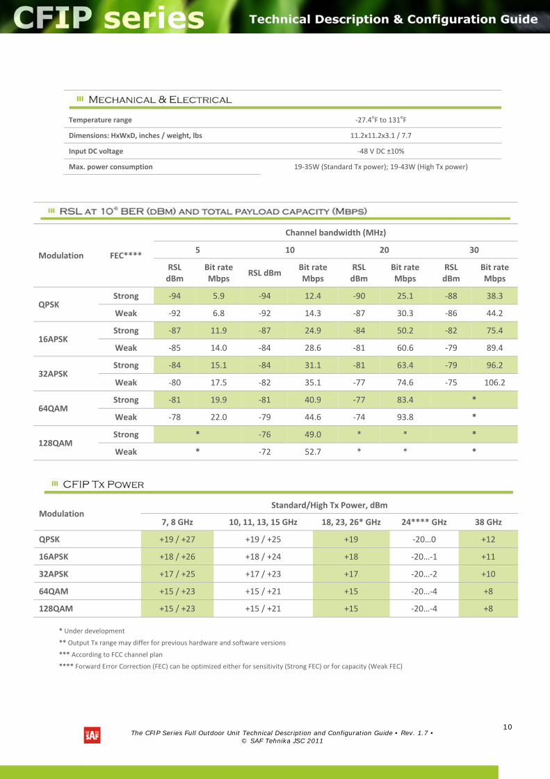
Modulation FEC****
Channel bandwidth (MHz)
5 10 20 30
RSL dBm
Bit rate Mbps
RSL dBm Bit rate Mbps
RSL dBm
Bit rate Mbps
RSL dBm
Bit rate Mbps
QPSK Strong ‐94 5.9 ‐94 12.4 ‐90 25.1 ‐88 38.3
Weak ‐92 6.8 ‐92 14.3 ‐87 30.3 ‐86 44.2
16APSK Strong ‐87 11.9 ‐87 24.9 ‐84 50.2 ‐82 75.4
Weak ‐85 14.0 ‐84 28.6 ‐81 60.6 ‐79 89.4
32APSK Strong ‐84 15.1 ‐84 31.1 ‐81 63.4 ‐79 96.2
Weak ‐80 17.5 ‐82 35.1 ‐77 74.6 ‐75 106.2
64QAM Strong ‐81 19.9 ‐81 40.9 ‐77 83.4 *
Weak ‐78 22.0 ‐79 44.6 ‐74 93.8 *
128QAM Strong * ‐76 49.0 * * *
Weak * ‐72 52.7 * * *
Modulation Standard/High Tx Power, dBm
7, 8 GHz 10, 11, 13, 15 GHz 18, 23, 26* GHz 24**** GHz 38 GHz
QPSK +19 / +27 +19 / +25 +19 ‐20…0 +12
16APSK +18 / +26 +18 / +24 +18 ‐20…‐1 +11
32APSK +17 / +25 +17 / +23 +17 ‐20…‐2 +10
64QAM +15 / +23 +15 / +21 +15 ‐20…‐4 +8
128QAM +15 / +23 +15 / +21 +15 ‐20…‐4 +8
* Under development
** Output Tx range may differ for previous hardware and software versions
*** According to FCC channel plan
**** Forward Error Correction (FEC) can be optimized either for sensitivity (Strong FEC) or for capacity (Weak FEC)
Temperature range ‐27.4oF to 131oF
Dimensions: HxWxD, inches / weight, lbs 11.2x11.2x3.1 / 7.7
Input DC voltage ‐48 V DC ±10%
Max. power consumption 19‐35W (Standard Tx power); 19‐43W (High Tx power)
The CFIP Series Full Outdoor Unit Technical Description and Configuration Guide • Rev. 1.7 •
© SAF Tehnika JSC 2011
11
1.6 Cable Requirements
RS‐232 Serial Connection
The ASCII console must be connected to the RS‐232 serial port with Twin‐BNC connector. This requires a twisted pair (TP) cable with common shield (foil and plaited shield); the cable must be suitable for Twin‐BNC connector.
Using a proper cable, the operation is guaranteed for up to 33 feet of cable.
4T1
The user equipment is connected to the CFIP‐106 FODU via twisted‐pair cable (at least 8 pairs, ‐ 16 wires), see Chapter 9 for pinouts. The 18‐pin connector is suited for cables with the diameter from 0.1575 to 0.4134 inches.
T1 signals will be carried properly over at least 328 feet of TP cable. The length of cable is restricted by the maximum allowable attenuation, which must not exceed 6 dB.
10/100Base‐T
Cat. 5e UTP or better cable is required for power supply, management of device and data traffic.
CFIP‐106 FODU can be used with any SAF Tehnika additionally provided Power over Ethernet sourcing equipment (provided power >50W). Used voltage is 48 V DC ± 10%, though the nominal voltage is 48 V, over two of the four available pairs on a Cat. 5e cable. It is possible to use passive injectors, utilizing spare leads. Refer to Chapter 9 for detailed information about pinouts.
Length of Cat. 5e cable must not exceed 328 feet.
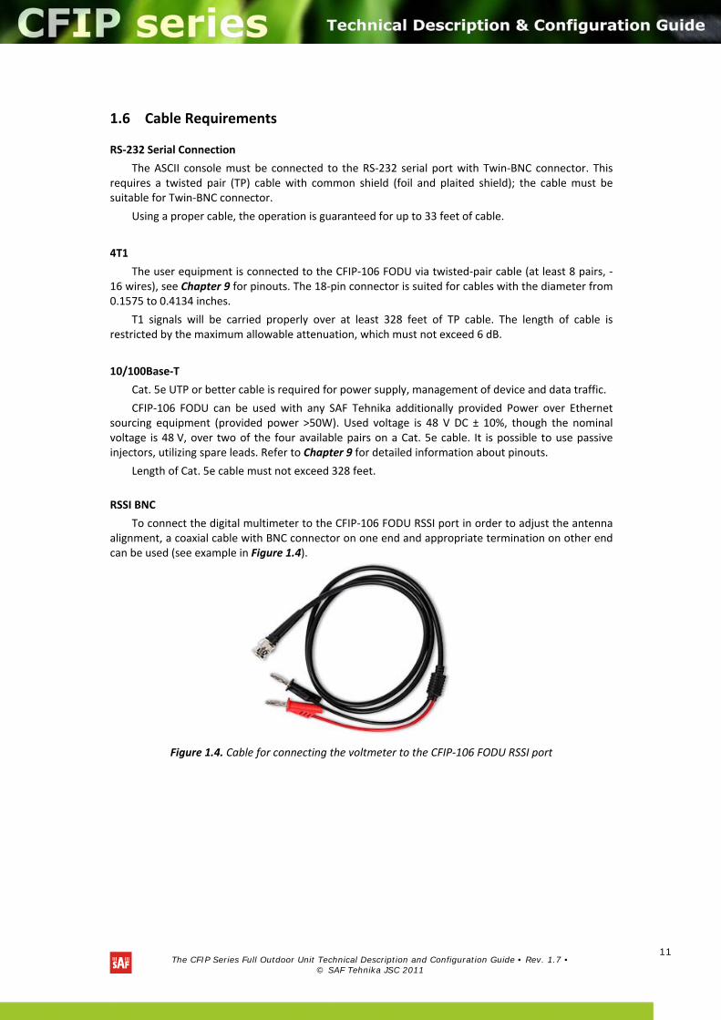
RSSI BNC
To connect the digital multimeter to the CFIP‐106 FODU RSSI port in order to adjust the antenna alignment, a coaxial cable with BNC connector on one end and appropriate termination on other end can be used (see example in Figure 1.4).
Figure 1.4. Cable for connecting the voltmeter to the CFIP‐106 FODU RSSI port
The CFIP Series Full Outdoor Unit Technical Description and Configuration Guide • Rev. 1.7 •
© SAF Tehnika JSC 2011
12
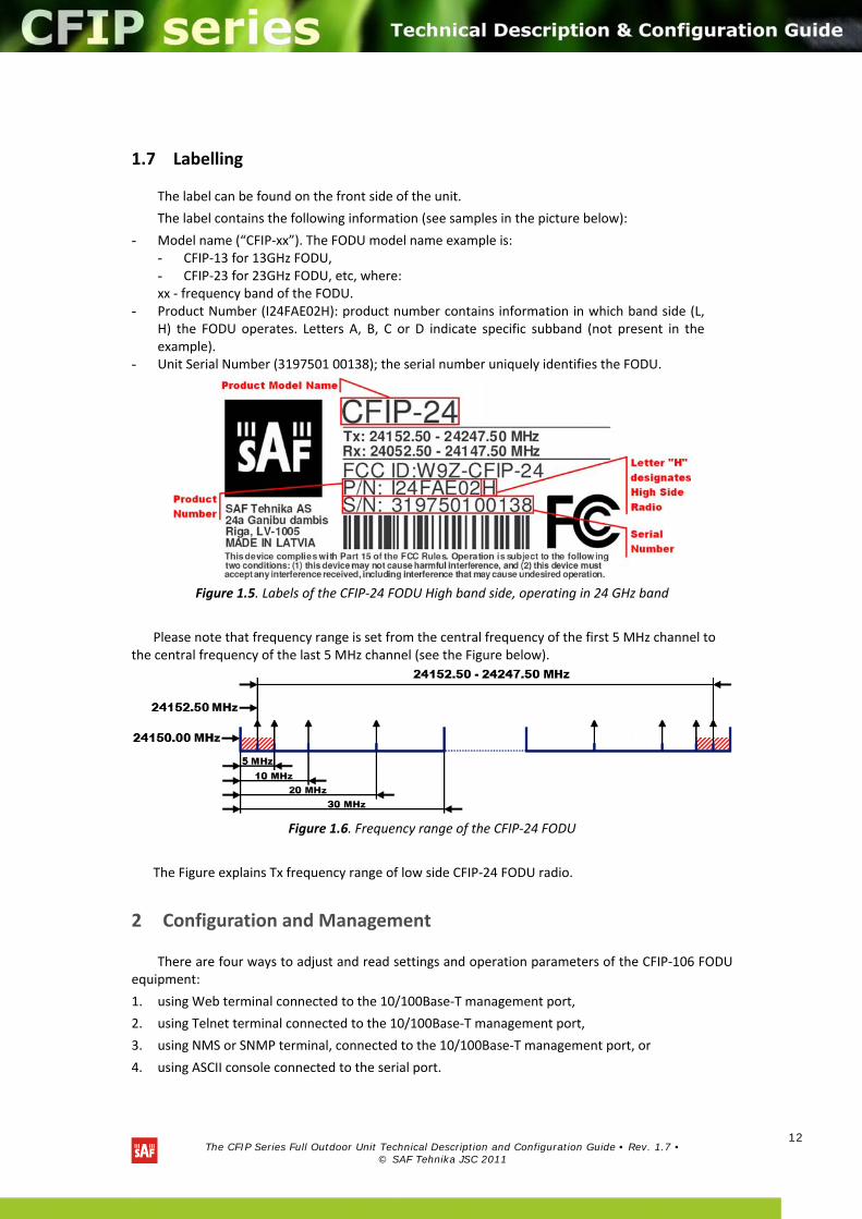
1.7 Labelling
The label can be found on the front side of the unit.
The label contains the following information (see samples in the picture below):
- Model name (“CFIP‐xx”). The FODU model name example is: - CFIP‐13 for 13GHz FODU, - CFIP‐23 for 23GHz FODU, etc, where: xx ‐ frequency band of the FODU.
- Product Number (I24FAE02H): product number contains information in which band side (L, H) the FODU operates. Letters A, B, C or D indicate specific subband (not present in the example).
- Unit Serial Number (3197501 00138); the serial number uniquely identifies the FODU.
Figure 1.5. Labels of the CFIP‐24 FODU High band side, operating in 24 GHz band
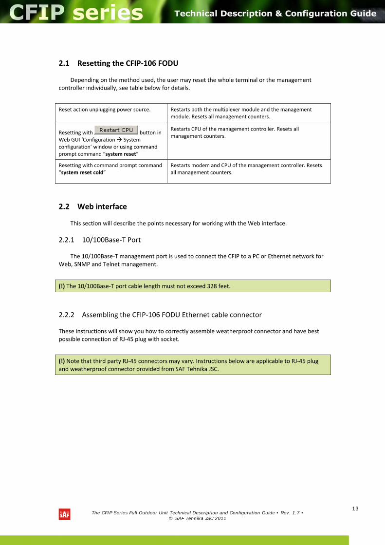
Please note that frequency range is set from the central frequency of the first 5 MHz channel to the central frequency of the last 5 MHz channel (see the Figure below).
Figure 1.6. Frequency range of the CFIP‐24 FODU
The Figure explains Tx frequency range of low side CFIP‐24 FODU radio.
2 Configuration and Management
There are four ways to adjust and read settings and operation parameters of the CFIP‐106 FODU equipment:
1. using Web terminal connected to the 10/100Base‐T management port,
2. using Telnet terminal connected to the 10/100Base‐T management port,
3. using NMS or SNMP terminal, connected to the 10/100Base‐T management port, or
4. using ASCII console connected to the serial port.
The CFIP Series Full Outdoor Unit Technical Description and Configuration Guide • Rev. 1.7 •
© SAF Tehnika JSC 2011
13
2.1 Resetting the CFIP‐106 FODU
Depending on the method used, the user may reset the whole terminal or the management controller individually, see table below for details.
Reset action unplugging power source. Restarts both the multiplexer module and the management module. Resets all management counters.
Resetting with button in Web GUI ‘Configuration System configuration’ window or using command prompt command “system reset”
Restarts CPU of the management controller. Resets all management counters.
Resetting with command prompt command “system reset cold”
Restarts modem and CPU of the management controller. Resets all management counters.
2.2 Web interface
This section will describe the points necessary for working with the Web interface.
2.2.1 10/100Base‐T Port
The 10/100Base‐T management port is used to connect the CFIP to a PC or Ethernet network for Web, SNMP and Telnet management.
(!) The 10/100Base‐T port cable length must not exceed 328 feet.
2.2.2 Assembling the CFIP‐106 FODU Ethernet cable connector
These instructions will show you how to correctly assemble weatherproof connector and have best possible connection of RJ‐45 plug with socket.
(!) Note that third party RJ‐45 connectors may vary. Instructions below are applicable to RJ‐45 plug and weatherproof connector provided from SAF Tehnika JSC.

The CFIP Series Full Outdoor Unit Technical Description and Configuration Guide • Rev. 1.7 •
© SAF Tehnika JSC 2011
14
Figure 2.1. Assembling sequence
Figure 2.2. Assembling weatherproof Ethernet connector
The CFIP Series Full Outdoor Unit Technical Description and Configuration Guide • Rev. 1.7 •
© SAF Tehnika JSC 2011
15
Fig. 2.2(1). Put rubber sealing inside the housing as shown. Fastening screw should be placed on the front part of housing.
(!) Note that locking pins of fastening screw should be aligned with slots on the housing. Unaligned attaching may result in broken locking pins.
Fig. 2.2(2). Put connector parts on the cable and crimp the RJ‐45 plug properly.
(!) RJ‐45 plug should be crimped with appropriate Tyco crimping tool 3‐231652‐0 (P/N I0ARJT01).
Fig. 2.2(3). Stick the rubber gasket on the housing.
Fig. 2.2(4). Insert RJ‐45 plug in the weatherproof housing.
Fig. 2.2(5). Fix the position using sealing screw.
Fig. 2.2(6). Connect RJ‐45 plug into the socket and fix the connector to the socket by turning fastening screw clockwise until there’s a click.
Fig. 2.2(7). Assembled connector. Fix the cable to the mast as close as possible to FODU. Do not bend it! The radius of bending should not be less than 10cm.
2.2.3 Ethernet management connection configuration
Before you proceed to initial link setup with Web GUI, you must perform Ethernet connection configuration by following these steps:
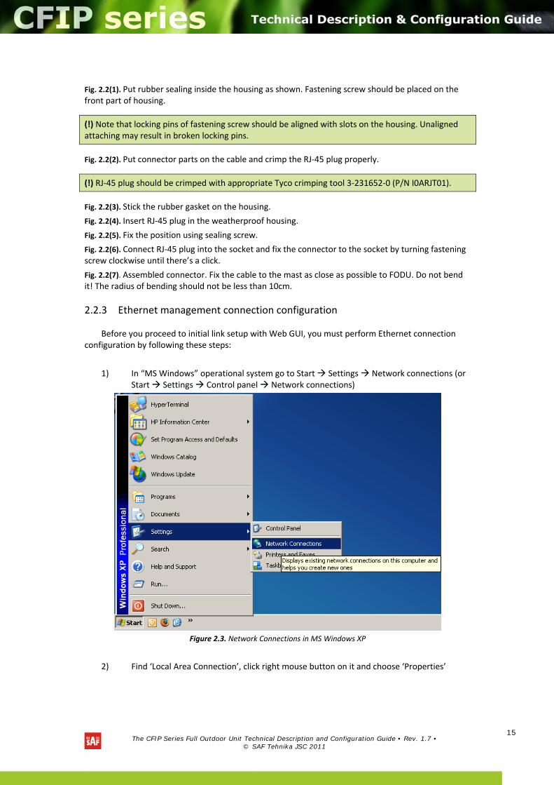
1) In “MS Windows” operational system go to Start Settings Network connections (or Start Settings Control panel Network connections)
Figure 2.3. Network Connections in MS Windows XP
2) Find ‘Local Area Connection’, click right mouse button on it and choose ‘Properties’
The CFIP Series Full Outdoor Unit Technical Description and Configuration Guide • Rev. 1.7 •
© SAF Tehnika JSC 2011
16
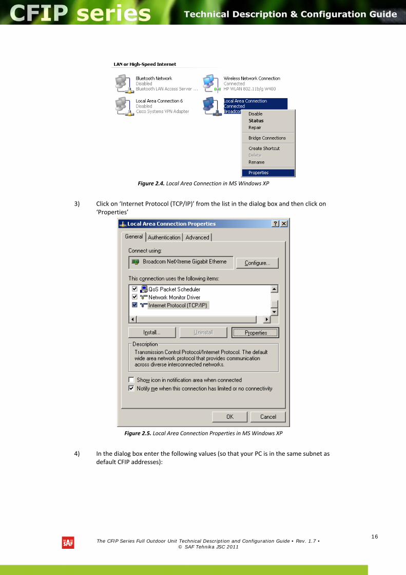
Figure 2.4. Local Area Connection in MS Windows XP
3) Click on ‘Internet Protocol (TCP/IP)’ from the list in the dialog box and then click on ‘Properties’
Figure 2.5. Local Area Connection Properties in MS Windows XP
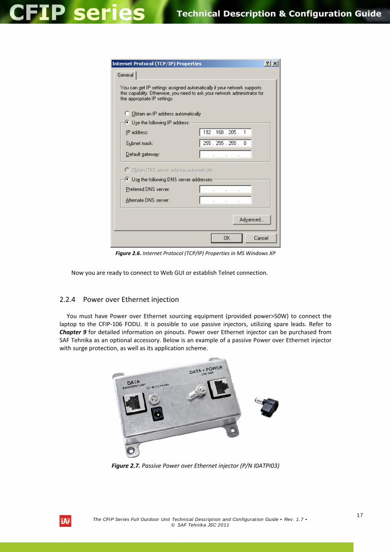
4) In the dialog box enter the following values (so that your PC is in the same subnet as default CFIP addresses):
The CFIP Series Full Outdoor Unit Technical Description and Configuration Guide • Rev. 1.7 •
© SAF Tehnika JSC 2011
17
Figure 2.6. Internet Protocol (TCP/IP) Properties in MS Windows XP
Now you are ready to connect to Web GUI or establish Telnet connection.
2.2.4 Power over Ethernet injection
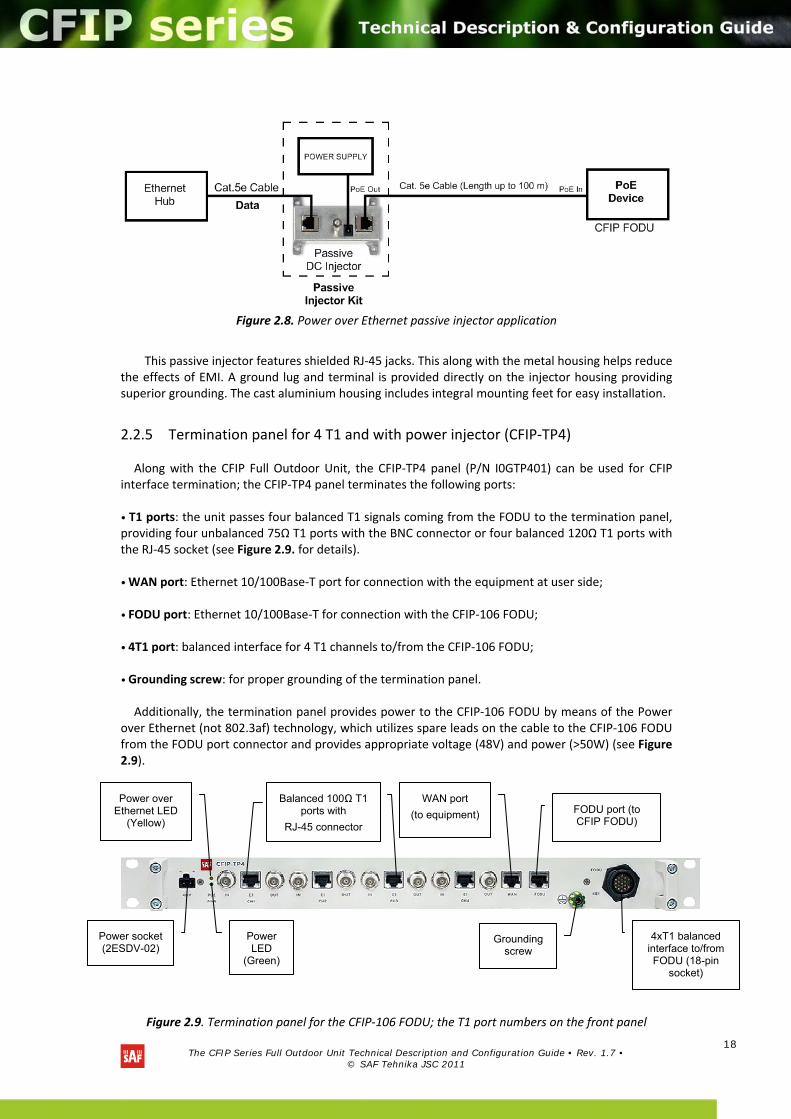
You must have Power over Ethernet sourcing equipment (provided power>50W) to connect the laptop to the CFIP‐106 FODU. It is possible to use passive injectors, utilizing spare leads. Refer to Chapter 9 for detailed information on pinouts. Power over Ethernet injector can be purchased from SAF Tehnika as an optional accessory. Below is an example of a passive Power over Ethernet injector with surge protection, as well as its application scheme.
Figure 2.7. Passive Power over Ethernet injector (P/N I0ATPI03)
The CFIP Series Full Outdoor Unit Technical Description and Configuration Guide • Rev. 1.7 •
© SAF Tehnika JSC 2011
18
Figure 2.8. Power over Ethernet passive injector application
This passive injector features shielded RJ‐45 jacks. This along with the metal housing helps reduce the effects of EMI. A ground lug and terminal is provided directly on the injector housing providing superior grounding. The cast aluminium housing includes integral mounting feet for easy installation.
2.2.5 Termination panel for 4 T1 and with power injector (CFIP‐TP4)
Along with the CFIP Full Outdoor Unit, the CFIP‐TP4 panel (P/N I0GTP401) can be used for CFIP interface termination; the CFIP‐TP4 panel terminates the following ports: • T1 ports: the unit passes four balanced T1 signals coming from the FODU to the termination panel, providing four unbalanced 75Ω T1 ports with the BNC connector or four balanced 120Ω T1 ports with the RJ‐45 socket (see Figure 2.9. for details). • WAN port: Ethernet 10/100Base‐T port for connection with the equipment at user side; • FODU port: Ethernet 10/100Base‐T for connection with the CFIP‐106 FODU; • 4T1 port: balanced interface for 4 T1 channels to/from the CFIP‐106 FODU; • Grounding screw: for proper grounding of the termination panel. Additionally, the termination panel provides power to the CFIP‐106 FODU by means of the Power
over Ethernet (not 802.3af) technology, which utilizes spare leads on the cable to the CFIP‐106 FODU from the FODU port connector and provides appropriate voltage (48V) and power (>50W) (see Figure 2.9).
Figure 2.9. Termination panel for the CFIP‐106 FODU; the T1 port numbers on the front panel
Power socket (2ESDV-02)
Power over Ethernet LED
(Yellow)
Power LED
(Green)
WAN port
(to equipment) FODU port (to CFIP FODU)
Grounding screw
4xT1 balanced interface to/from FODU (18-pin
socket)
Balanced 100Ω T1 ports with
RJ-45 connector
The CFIP Series Full Outdoor Unit Technical Description and Configuration Guide • Rev. 1.7 •
© SAF Tehnika JSC 2011
19
correspond to the CFIP‐106 FODU port numbering. The termination panel also features full surge protection, meeting ITU‐T K.20/K.21/K.44/K.45
recommendations and ETSI ETS 301 489 standard.
Power LEDs on the termination panel show if the power is being fed to the termination panel
(Green LED), and if the CFIP‐106 FODU is powered on (Yellow). The CFIP‐TP4 unit is optional and can be used with any of the CFIP Full Outdoor Units. It is
frequency and capacity independent. CFIP‐TP4 panel mechanical data: − Dimensions (HxWxD): 1.73 x 19.0 x 2.126 in; − Weight: 1.32 lbs.
2.2.6 Connection with Web interface
It is recommended to use the following web‐browsers (and all later versions):
IE v. 6.0
Mozilla Firefox v. 2.0.0.11
Safari v. 3.0
Opera v. 9.50
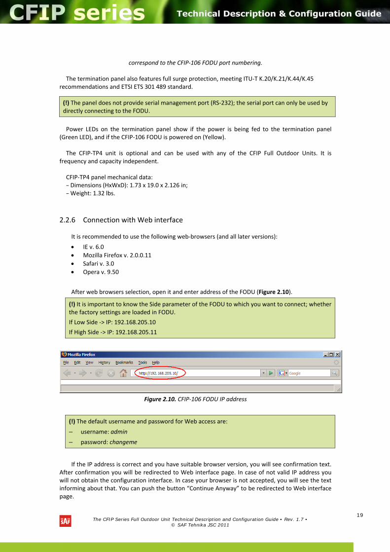
After web browsers selection, open it and enter address of the FODU (Figure 2.10).
(!) It is important to know the Side parameter of the FODU to which you want to connect; whether the factory settings are loaded in FODU.
If Low Side ‐> IP: 192.168.205.10
If High Side ‐> IP: 192.168.205.11
Figure 2.10. CFIP‐106 FODU IP address
(!) The default username and password for Web access are:
– username: admin
– password: changeme
If the IP address is correct and you have suitable browser version, you will see confirmation text. After confirmation you will be redirected to Web interface page. In case of not valid IP address you will not obtain the configuration interface. In case your browser is not accepted, you will see the text informing about that. You can push the button “Continue Anyway” to be redirected to Web interface page.
(!) The panel does not provide serial management port (RS‐232); the serial port can only be used by directly connecting to the FODU.
The CFIP Series Full Outdoor Unit Technical Description and Configuration Guide • Rev. 1.7 •
© SAF Tehnika JSC 2011
20
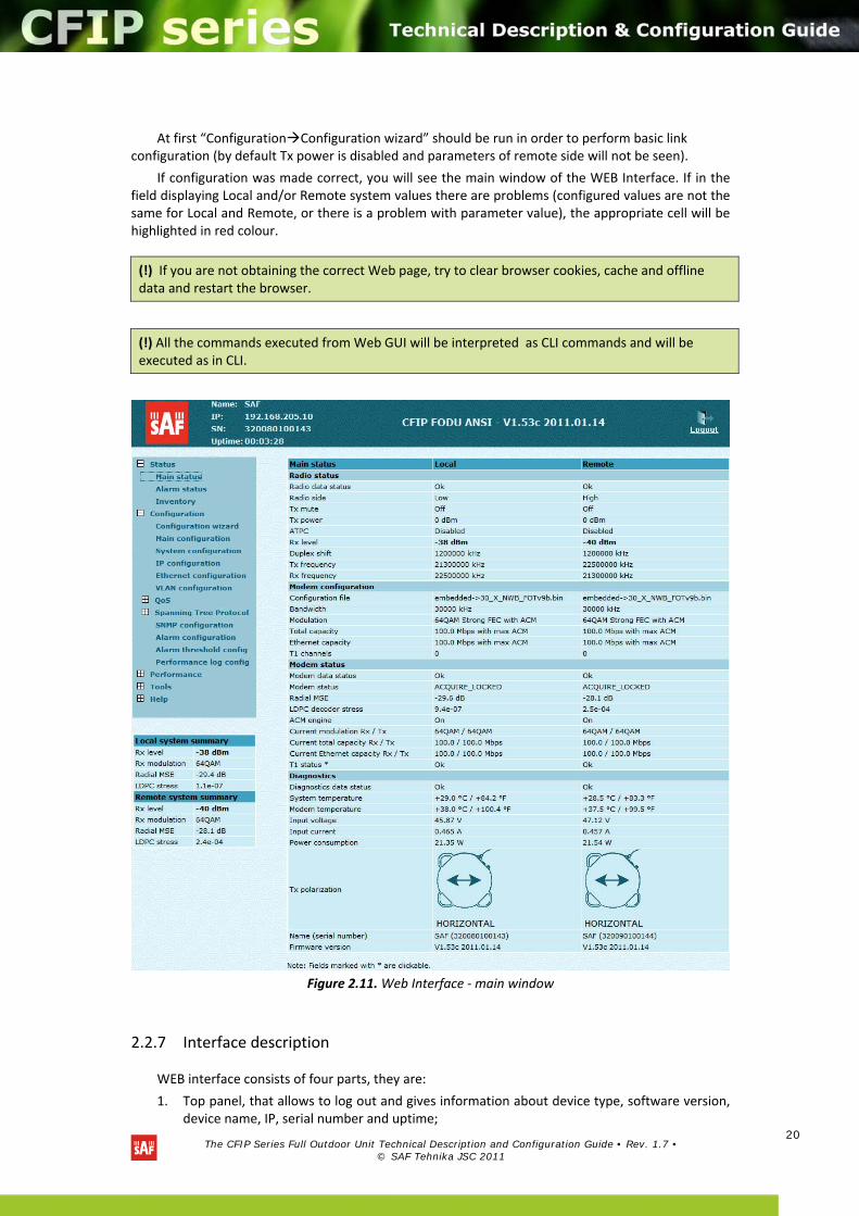
At first “ConfigurationConfiguration wizard” should be run in order to perform basic link configuration (by default Tx power is disabled and parameters of remote side will not be seen).
If configuration was made correct, you will see the main window of the WEB Interface. If in the field displaying Local and/or Remote system values there are problems (configured values are not the same for Local and Remote, or there is a problem with parameter value), the appropriate cell will be highlighted in red colour.
Figure 2.11. Web Interface ‐ main window
2.2.7 Interface description
WEB interface consists of four parts, they are:
1. Top panel, that allows to log out and gives information about device type, software version, device name, IP, serial number and uptime;
(!) If you are not obtaining the correct Web page, try to clear browser cookies, cache and offline data and restart the browser.
(!) All the commands executed from Web GUI will be interpreted as CLI commands and will be executed as in CLI.
The CFIP Series Full Outdoor Unit Technical Description and Configuration Guide • Rev. 1.7 •
© SAF Tehnika JSC 2011
21
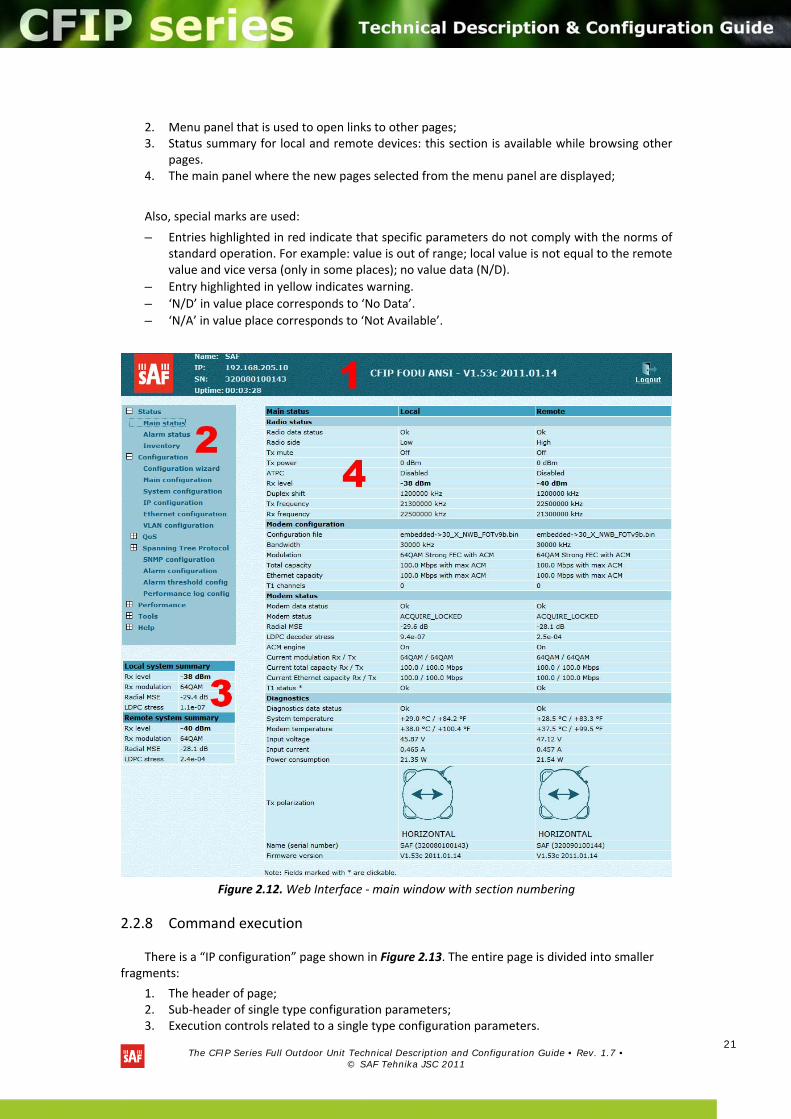
2. Menu panel that is used to open links to other pages; 3. Status summary for local and remote devices: this section is available while browsing other
pages. 4. The main panel where the new pages selected from the menu panel are displayed;
Also, special marks are used:
– Entries highlighted in red indicate that specific parameters do not comply with the norms of standard operation. For example: value is out of range; local value is not equal to the remote value and vice versa (only in some places); no value data (N/D).
– Entry highlighted in yellow indicates warning.
– ‘N/D’ in value place corresponds to ‘No Data’.
– ‘N/A’ in value place corresponds to ‘Not Available’.
Figure 2.12. Web Interface ‐ main window with section numbering
2.2.8 Command execution
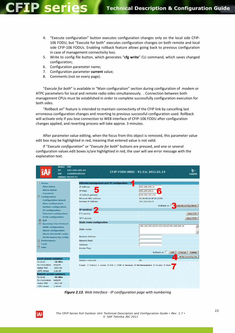
There is a “IP configuration” page shown in Figure 2.13. The entire page is divided into smaller fragments:
1. The header of page; 2. Sub‐header of single type configuration parameters; 3. Execution controls related to a single type configuration parameters.
The CFIP Series Full Outdoor Unit Technical Description and Configuration Guide • Rev. 1.7 •
© SAF Tehnika JSC 2011
22
4. “Execute configuration” button executes configuration changes only on the local side CFIP‐106 FODU, but “Execute for both” executes configuration changes on both remote and local side CFIP‐106 FODUs. Enabling rollback feature allows going back to previous configuration in case of management connectivity loss.
5. Write to config file button, which generates “cfg write” CLI command, which saves changed configuration;
6. Configuration parameter name; 7. Configuration parameter current value; 8. Comments (not on every page).
“Execute for both” is available in “Main configuration” section during configuration of modem or ATPC parameters for local and remote radio sides simultaneously. . Connection between both management CPUs must be established in order to complete successfully configuration execution for both sides.
“Rollback on” feature is intended to maintain connectivity of the CFIP link by cancelling last erroneous configuration changes and reverting to previous successful configuration used. Rollback will activate only if you lose connection to WEB interface of CFIP‐106 FODU after configuration changes applied, and reverting process will take approx. 3 minutes.
After parameter value editing, when the focus from this object is removed, this parameter value edit box may be highlighted in red, meaning that entered value is not valid.
If “Execute configuration” or “Execute for both” buttons are pressed, and one or several configuration values edit boxes is/are highlighted in red, the user will see error message with the explanation text.
Figure 2.13. Web Interface ‐ IP configuration page with numbering
The CFIP Series Full Outdoor Unit Technical Description and Configuration Guide • Rev. 1.7 •
© SAF Tehnika JSC 2011
23
2.2.9 Initial configuration with Web GUI
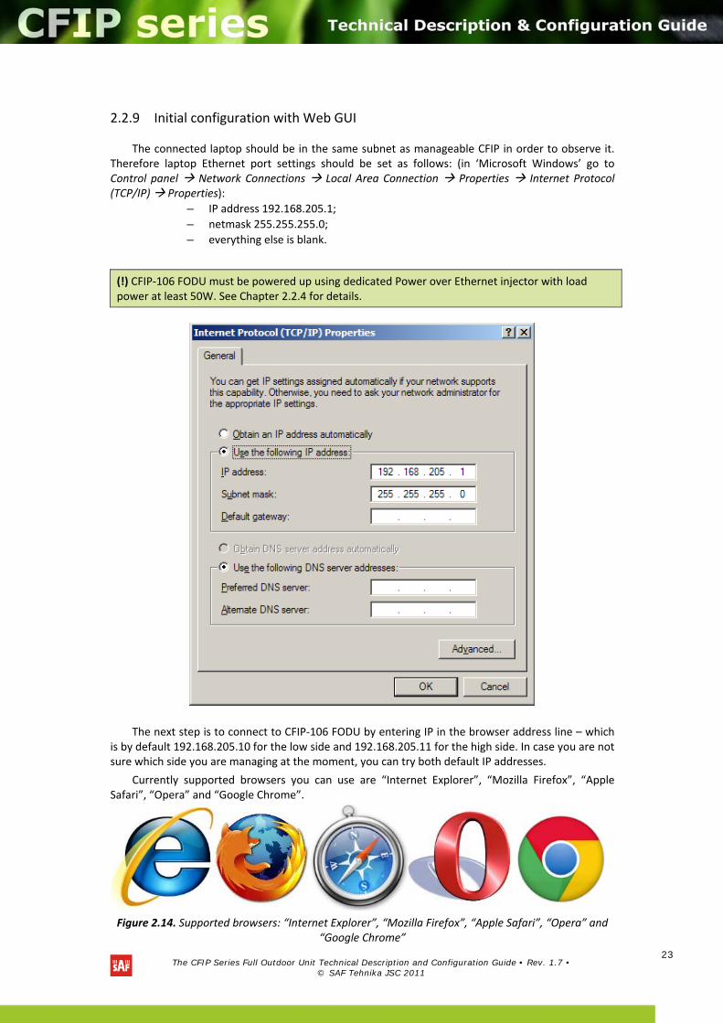
The connected laptop should be in the same subnet as manageable CFIP in order to observe it. Therefore laptop Ethernet port settings should be set as follows: (in ‘Microsoft Windows’ go to Control panel Network Connections Local Area Connection Properties Internet Protocol (TCP/IP) Properties):
– IP address 192.168.205.1;
– netmask 255.255.255.0;
– everything else is blank.
The next step is to connect to CFIP‐106 FODU by entering IP in the browser address line – which is by default 192.168.205.10 for the low side and 192.168.205.11 for the high side. In case you are not sure which side you are managing at the moment, you can try both default IP addresses.
Currently supported browsers you can use are “Internet Explorer”, “Mozilla Firefox”, “Apple Safari”, “Opera” and “Google Chrome”.
Figure 2.14. Supported browsers: “Internet Explorer”, “Mozilla Firefox”, “Apple Safari”, “Opera” and “Google Chrome”
(!) CFIP‐106 FODU must be powered up using dedicated Power over Ethernet injector with load power at least 50W. See Chapter 2.2.4 for details.
The CFIP Series Full Outdoor Unit Technical Description and Configuration Guide • Rev. 1.7 •
© SAF Tehnika JSC 2011
24
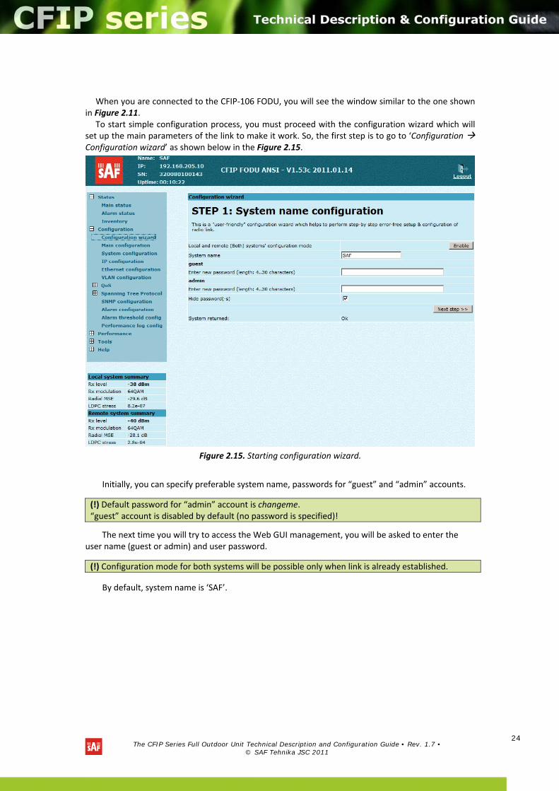
When you are connected to the CFIP‐106 FODU, you will see the window similar to the one shown
in Figure 2.11. To start simple configuration process, you must proceed with the configuration wizard which will
set up the main parameters of the link to make it work. So, the first step is to go to ‘Configuration Configuration wizard’ as shown below in the Figure 2.15.
Figure 2.15. Starting configuration wizard.
Initially, you can specify preferable system name, passwords for “guest” and “admin” accounts.
The next time you will try to access the Web GUI management, you will be asked to enter the user name (guest or admin) and user password.
By default, system name is ‘SAF’.
(!) Default password for “admin” account is changeme.“guest” account is disabled by default (no password is specified)!
(!) Configuration mode for both systems will be possible only when link is already established.
The CFIP Series Full Outdoor Unit Technical Description and Configuration Guide • Rev. 1.7 •
© SAF Tehnika JSC 2011
25
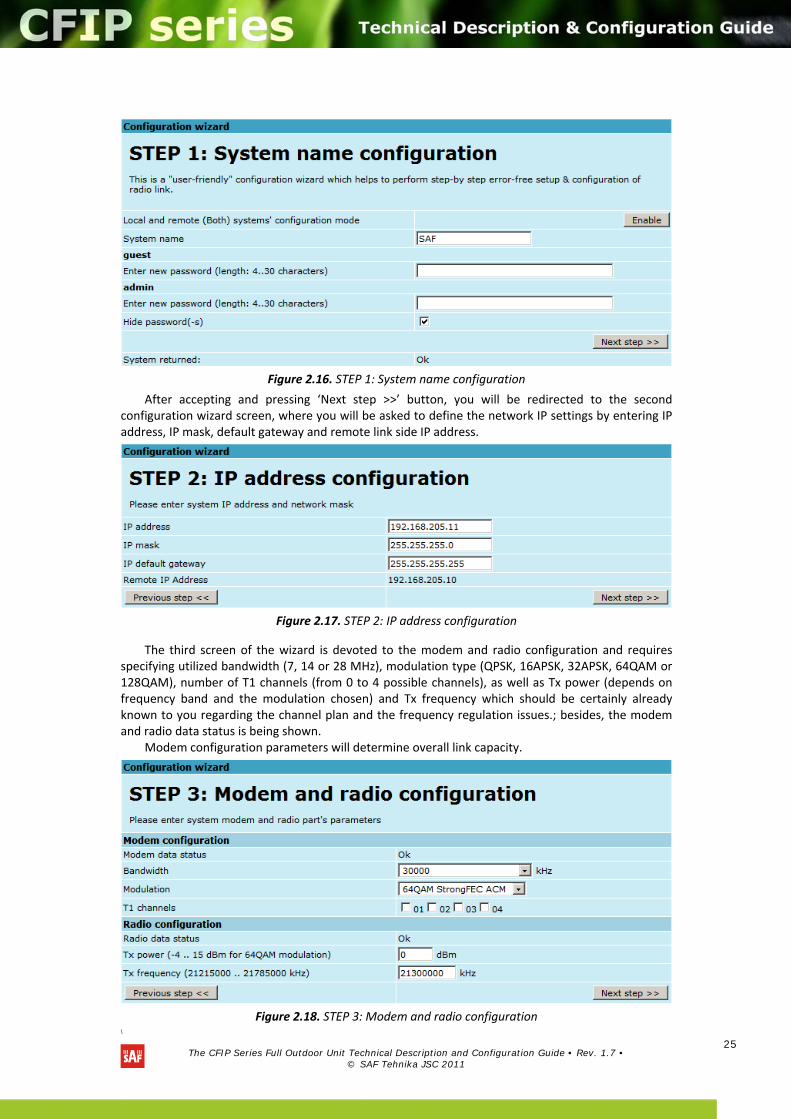
Figure 2.16. STEP 1: System name configuration
After accepting and pressing ‘Next step >>’ button, you will be redirected to the second configuration wizard screen, where you will be asked to define the network IP settings by entering IP address, IP mask, default gateway and remote link side IP address.
Figure 2.17. STEP 2: IP address configuration
The third screen of the wizard is devoted to the modem and radio configuration and requires specifying utilized bandwidth (7, 14 or 28 MHz), modulation type (QPSK, 16APSK, 32APSK, 64QAM or 128QAM), number of T1 channels (from 0 to 4 possible channels), as well as Tx power (depends on frequency band and the modulation chosen) and Tx frequency which should be certainly already known to you regarding the channel plan and the frequency regulation issues.; besides, the modem and radio data status is being shown.
Modem configuration parameters will determine overall link capacity.
Figure 2.18. STEP 3: Modem and radio configuration
\
The CFIP Series Full Outdoor Unit Technical Description and Configuration Guide • Rev. 1.7 •
© SAF Tehnika JSC 2011
26
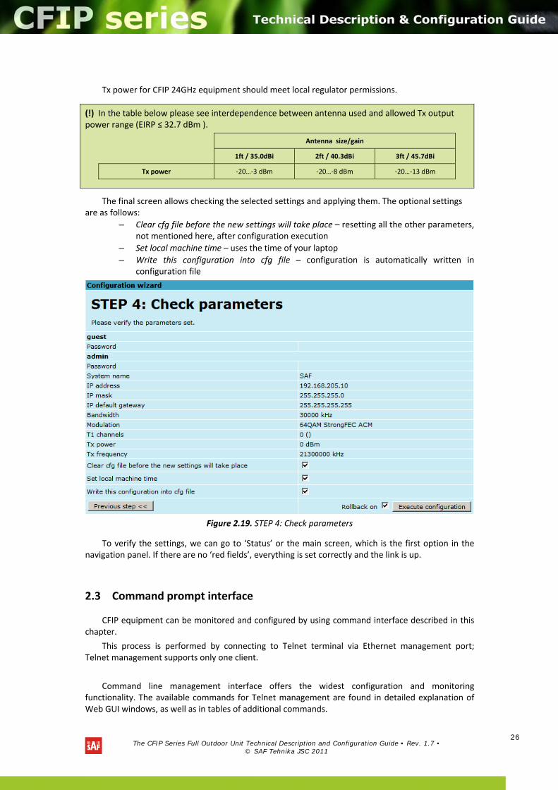
Tx power for CFIP 24GHz equipment should meet local regulator permissions.
The final screen allows checking the selected settings and applying them. The optional settings are as follows:
– Clear cfg file before the new settings will take place – resetting all the other parameters, not mentioned here, after configuration execution
– Set local machine time – uses the time of your laptop
– Write this configuration into cfg file – configuration is automatically written in configuration file
Figure 2.19. STEP 4: Check parameters
To verify the settings, we can go to ‘Status’ or the main screen, which is the first option in the navigation panel. If there are no ‘red fields’, everything is set correctly and the link is up.
2.3 Command prompt interface
CFIP equipment can be monitored and configured by using command interface described in this chapter.
This process is performed by connecting to Telnet terminal via Ethernet management port; Telnet management supports only one client.
Command line management interface offers the widest configuration and monitoring functionality. The available commands for Telnet management are found in detailed explanation of Web GUI windows, as well as in tables of additional commands.
(!) In the table below please see interdependence between antenna used and allowed Tx output power range (EIRP ≤ 32.7 dBm ).
Antenna size/gain
1ft / 35.0dBi 2ft / 40.3dBi 3ft / 45.7dBi
Tx power ‐20…‐3 dBm ‐20…‐8 dBm ‐20…‐13 dBm
The CFIP Series Full Outdoor Unit Technical Description and Configuration Guide • Rev. 1.7 •
© SAF Tehnika JSC 2011
27
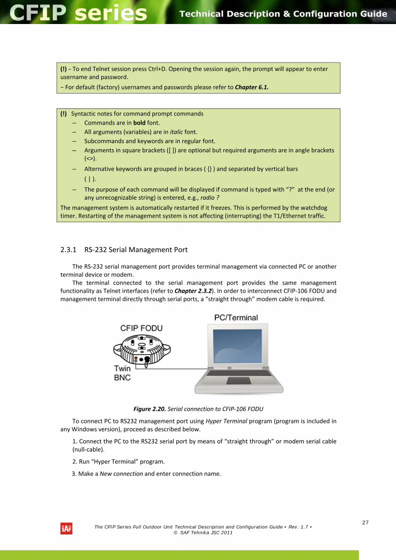
2.3.1 RS‐232 Serial Management Port
The RS‐232 serial management port provides terminal management via connected PC or another terminal device or modem.
The terminal connected to the serial management port provides the same management functionality as Telnet interfaces (refer to Chapter 2.3.2). In order to interconnect CFIP‐106 FODU and management terminal directly through serial ports, a “straight through” modem cable is required.
Figure 2.20. Serial connection to CFIP‐106 FODU
To connect PC to RS232 management port using Hyper Terminal program (program is included in any Windows version), proceed as described below.
1. Connect the PC to the RS232 serial port by means of “straight through” or modem serial cable (null‐cable).
2. Run “Hyper Terminal” program.
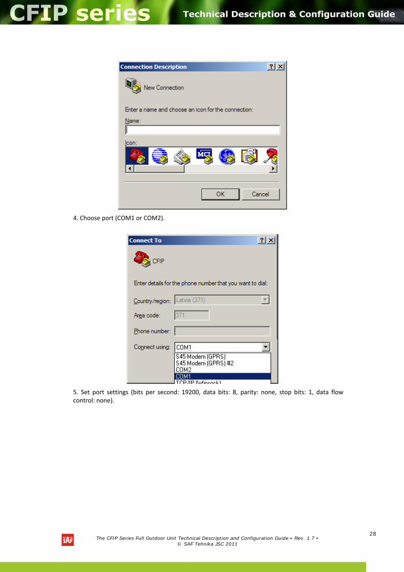
3. Make a New connection and enter connection name.
(!) − To end Telnet session press Ctrl+D. Opening the session again, the prompt will appear to enter username and password.
− For default (factory) usernames and passwords please refer to Chapter 6.1.
(!) Syntactic notes for command prompt commands
– Commands are in bold font.
– All arguments (variables) are in italic font.
– Subcommands and keywords are in regular font.
– Arguments in square brackets ([ ]) are optional but required arguments are in angle brackets (<>).
– Alternative keywords are grouped in braces ( ) and separated by vertical bars
( | ).
– The purpose of each command will be displayed if command is typed with “?” at the end (or any unrecognizable string) is entered, e.g., radio ?
The management system is automatically restarted if it freezes. This is performed by the watchdog timer. Restarting of the management system is not affecting (interrupting) the T1/Ethernet traffic.
The CFIP Series Full Outdoor Unit Technical Description and Configuration Guide • Rev. 1.7 •
© SAF Tehnika JSC 2011
28
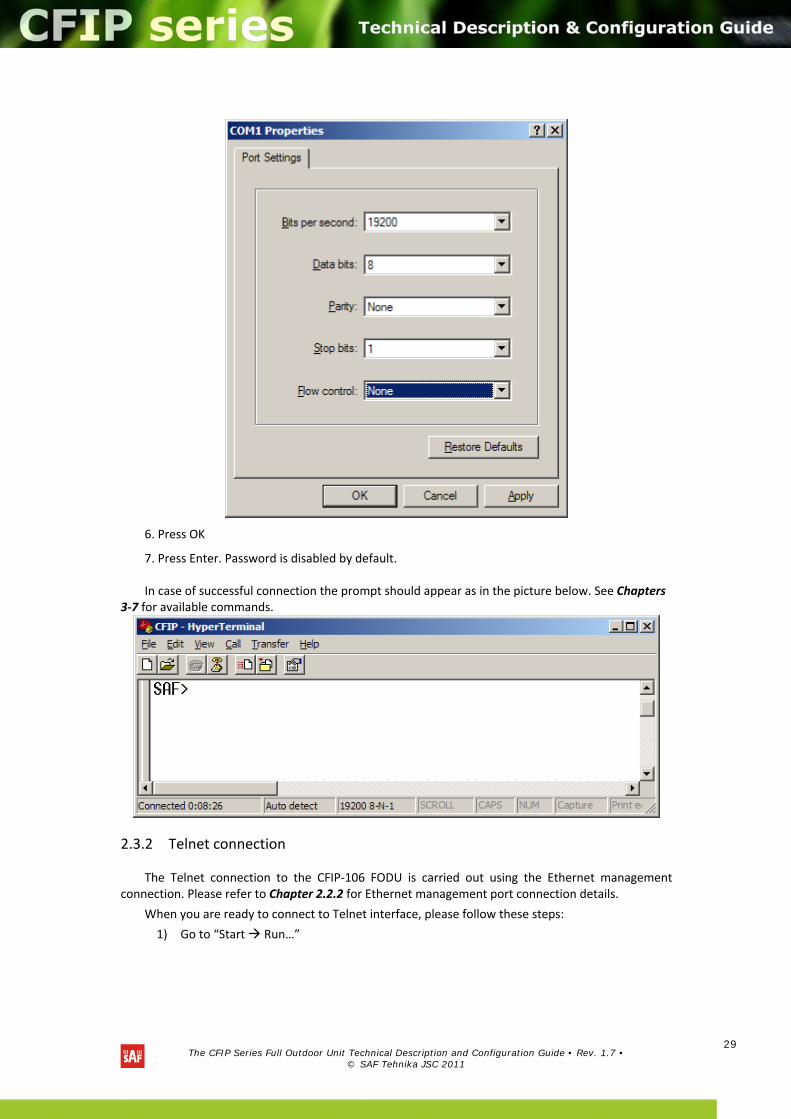
4. Choose port (COM1 or COM2).
5. Set port settings (bits per second: 19200, data bits: 8, parity: none, stop bits: 1, data flow control: none).
The CFIP Series Full Outdoor Unit Technical Description and Configuration Guide • Rev. 1.7 •
© SAF Tehnika JSC 2011
29
6. Press OK
7. Press Enter. Password is disabled by default.
In case of successful connection the prompt should appear as in the picture below. See Chapters 3‐7 for available commands.
2.3.2 Telnet connection
The Telnet connection to the CFIP‐106 FODU is carried out using the Ethernet management connection. Please refer to Chapter 2.2.2 for Ethernet management port connection details.
When you are ready to connect to Telnet interface, please follow these steps:
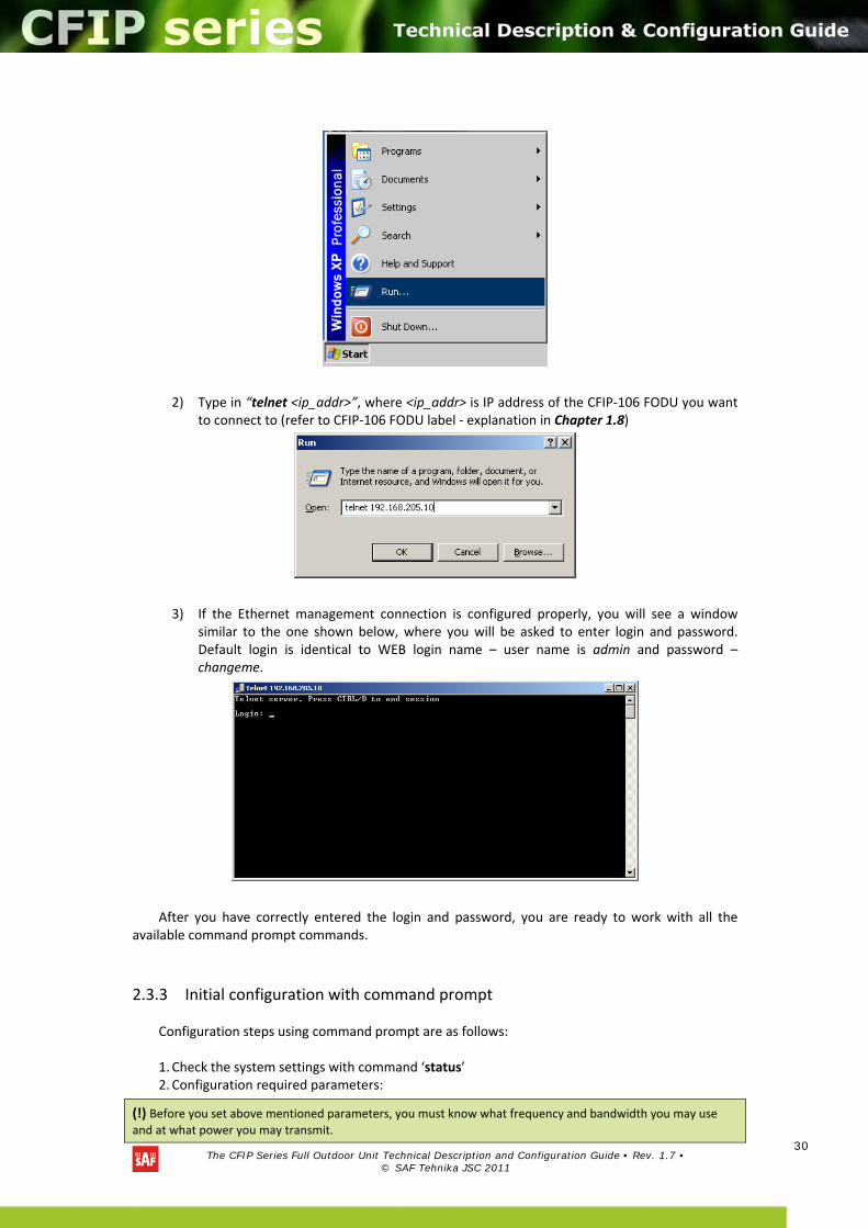
1) Go to “Start Run…”
The CFIP Series Full Outdoor Unit Technical Description and Configuration Guide • Rev. 1.7 •
© SAF Tehnika JSC 2011
30
2) Type in “telnet <ip_addr>”, where <ip_addr> is IP address of the CFIP‐106 FODU you want to connect to (refer to CFIP‐106 FODU label ‐ explanation in Chapter 1.8)
3) If the Ethernet management connection is configured properly, you will see a window similar to the one shown below, where you will be asked to enter login and password. Default login is identical to WEB login name – user name is admin and password – changeme.
After you have correctly entered the login and password, you are ready to work with all the available command prompt commands.
2.3.3 Initial configuration with command prompt
Configuration steps using command prompt are as follows: 1. Check the system settings with command ‘status’ 2. Configuration required parameters:
(!) Before you set above mentioned parameters, you must know what frequency and bandwidth you may use
and at what power you may transmit.
The CFIP Series Full Outdoor Unit Technical Description and Configuration Guide • Rev. 1.7 •
© SAF Tehnika JSC 2011
31
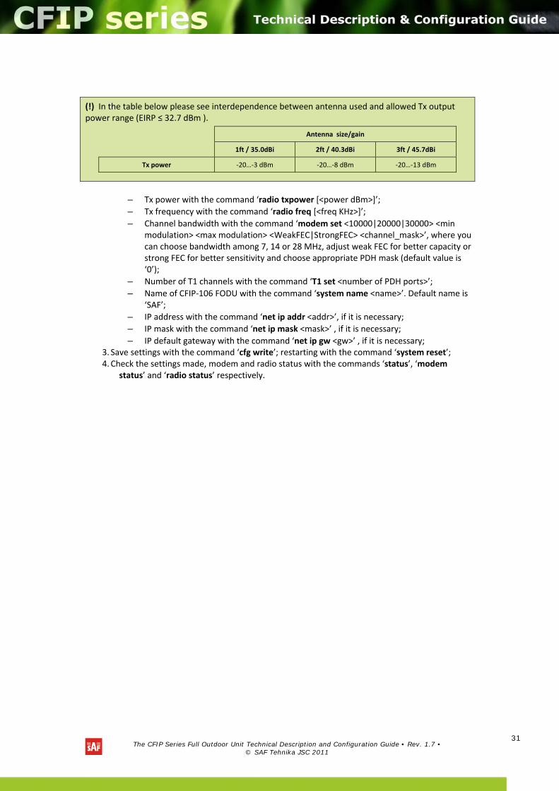
– Tx power with the command ‘radio txpower [<power dBm>]’;
– Tx frequency with the command ‘radio freq [<freq KHz>]’;
– Channel bandwidth with the command ‘modem set <10000|20000|30000> <min modulation> <max modulation> <WeakFEC|StrongFEC> <channel_mask>’, where you can choose bandwidth among 7, 14 or 28 MHz, adjust weak FEC for better capacity or strong FEC for better sensitivity and choose appropriate PDH mask (default value is ‘0’);
– Number of T1 channels with the command ‘T1 set <number of PDH ports>’;
– Name of CFIP‐106 FODU with the command ‘system name <name>’. Default name is ‘SAF’;
– IP address with the command ‘net ip addr <addr>’, if it is necessary;
– IP mask with the command ‘net ip mask <mask>’ , if it is necessary;
– IP default gateway with the command ‘net ip gw <gw>’ , if it is necessary; 3. Save settings with the command ‘cfg write’; restarting with the command ‘system reset’; 4. Check the settings made, modem and radio status with the commands ‘status’, ‘modem
status’ and ‘radio status’ respectively.
(!) In the table below please see interdependence between antenna used and allowed Tx output power range (EIRP ≤ 32.7 dBm ).
Antenna size/gain
1ft / 35.0dBi 2ft / 40.3dBi 3ft / 45.7dBi
Tx power ‐20…‐3 dBm ‐20…‐8 dBm ‐20…‐13 dBm
The CFIP Series Full Outdoor Unit Technical Description and Configuration Guide • Rev. 1.7 •
© SAF Tehnika JSC 2011
32
3 Status window
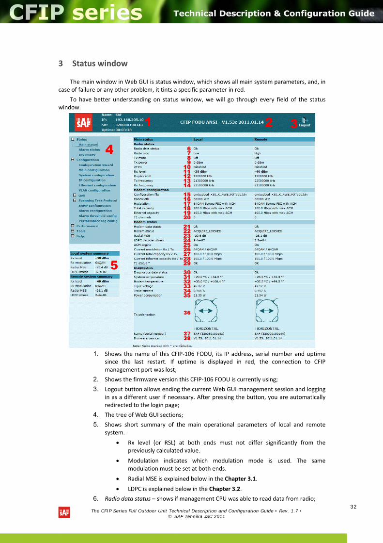
The main window in Web GUI is status window, which shows all main system parameters, and, in case of failure or any other problem, it tints a specific parameter in red.
To have better understanding on status window, we will go through every field of the status window.
1. Shows the name of this CFIP‐106 FODU, its IP address, serial number and uptime since the last restart. If uptime is displayed in red, the connection to CFIP management port was lost;
2. Shows the firmware version this CFIP‐106 FODU is currently using;
3. Logout button allows ending the current Web GUI management session and logging in as a different user if necessary. After pressing the button, you are automatically redirected to the login page;
4. The tree of Web GUI sections;
5. Shows short summary of the main operational parameters of local and remote system.
Rx level (or RSL) at both ends must not differ significantly from the previously calculated value.
Modulation indicates which modulation mode is used. The same modulation must be set at both ends.
Radial MSE is explained below in the Chapter 3.1.
LDPC is explained below in the Chapter 3.2.
6. Radio data status – shows if management CPU was able to read data from radio;
The CFIP Series Full Outdoor Unit Technical Description and Configuration Guide • Rev. 1.7 •
© SAF Tehnika JSC 2011
33
7. Radio side – shows the radio side of local and remote CFIP (command line – radio side);
8. Tx mute – shows if transmitter is currently muted;
9. Tx power – shows current transmitter power in dBm (command line ‐ radio status or status);
10. ATPC – shows the amount of current ATPC correction in dBm (command line – atpc status);
11. Rx level – shows current level of received signal. It must not differ significantly from the previously calculated value (command line ‐ radio status or status);
12. Duplex shift – shows the margin between the transmitting and receiving frequencies (command line ‐ radio status);
13. Tx frequency – shows the transmitting frequency (command line ‐ radio status);
14. Rx frequency – shows the receiving frequency (command line ‐ radio status);
15. Configuration file – shows which configuration the modem is currently using (command line – modem configuration);
16. Bandwidth – shows width of currently utilized bandwidth in MHz (command line – modem status or status);
17. Modulation – shows modulation mode set (command line – modem status or status);
18. Total capacity – shows total capacity set (command line – modem status);
19. Ethernet capacity – shows Ethernet capacity set (command line – modem status or status);
20. T1 channels – shows the number of T1 channels set. The number must be equal at both ends (command line – modem status or status);
21. Modem data status – shows if management CPU was able to read data from modem;
22. Modem status – indicates the acquire status of the modem. ‘ACQUIRE_IN_PROGRESS’ will appear during start‐up, when modem acquires required parameters, but in normal operation mode ‘ACQUIRE_LOCKED’ will be seen. Any other options designate failure (command line – modem status or status);
23. Radial MSE – shows radial mean square error value. Refer to Chapter 3.1. for detailed description (command line ‐ modem status or status);
24. LDPC decoder stress – shows the load of LDPC (low‐density parity‐check code) decoder. Refer to Chapter 3.2. for detailed description (command line – modem status or status);
25. ACM engine – shows if ACM (Adaptive Coding and Modulation) engine is running (command line – modem status or status);
26. Current modulation Rx / Tx – shows the modulation modes currently utilized (command line – modem status);
27. Current total capacity Rx / Tx – shows the current capacities in both directions (command line – modem status);
28. Current Ethernet capacity Rx / Tx – shows the current Ethernet capacities in both directions (command line – modem status);
29. T1 status – shows if the T1 channel is connected or not and shows status of LOS and AIS indications. To see the status, click on the text (command line – T1 status);
30. Diagnostics data status – shows if system parameters are in acceptable margins (command line ‐ diagnostics);
31. System temperature – shows the device internal temperature in degrees by Celsius (command line ‐ diagnostics or status);
The CFIP Series Full Outdoor Unit Technical Description and Configuration Guide • Rev. 1.7 •
© SAF Tehnika JSC 2011
34
32. Modem temperature – shows the temperature on modem in degrees by Celsius (command line ‐ diagnostics or status);
33. Input voltage – shows the input voltage in volts (command line ‐ diagnostics);
34. Current – shows the current in amperes (command line ‐ diagnostics);
35. Consume power – shows the amount of power consumed in watts (command line ‐ diagnostics);
36. Tx polarization – shows transmission polarization and position of connectors and wires at the local side (command line ‐ diagnostics);
37. Name (serial number) – shows system name and serial number (command line – system name and system inventory);
38. Firmware version – shows current firmware version. Make sure it is the same on both ends of the link (command line – ver).
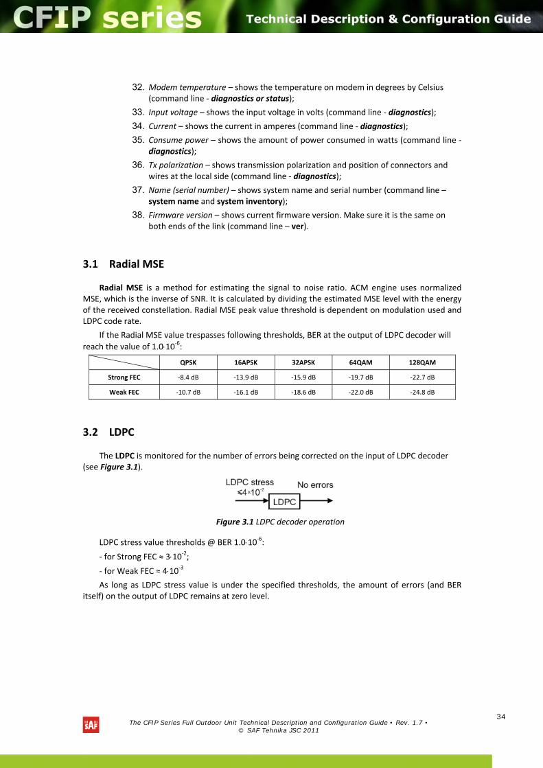
3.1 Radial MSE
Radial MSE is a method for estimating the signal to noise ratio. ACM engine uses normalized MSE, which is the inverse of SNR. It is calculated by dividing the estimated MSE level with the energy of the received constellation. Radial MSE peak value threshold is dependent on modulation used and LDPC code rate.
If the Radial MSE value trespasses following thresholds, BER at the output of LDPC decoder will
reach the value of 1.010‐6:
QPSK 16APSK 32APSK 64QAM 128QAM
Strong FEC ‐8.4 dB ‐13.9 dB ‐15.9 dB ‐19.7 dB ‐22.7 dB
Weak FEC ‐10.7 dB ‐16.1 dB ‐18.6 dB ‐22.0 dB ‐24.8 dB
3.2 LDPC
The LDPC is monitored for the number of errors being corrected on the input of LDPC decoder (see Figure 3.1).
Figure 3.1 LDPC decoder operation
LDPC stress value thresholds @ BER 1.010‐6:
‐ for Strong FEC ≈ 310‐2;
‐ for Weak FEC ≈ 410‐3 As long as LDPC stress value is under the specified thresholds, the amount of errors (and BER
itself) on the output of LDPC remains at zero level.
The CFIP Series Full Outdoor Unit Technical Description and Configuration Guide • Rev. 1.7 •
© SAF Tehnika JSC 2011
35
4 Detailed configuration in Web graphic user interface
Configuration section in Web interface allows customizing your system to suit your specific needs.
4.1 Main configuration
The main configuration window provides the configuration of most vital system parameters, including the ones in configuration wizard as well as some other important parameters. Below is a short explanation of provided customization fields.
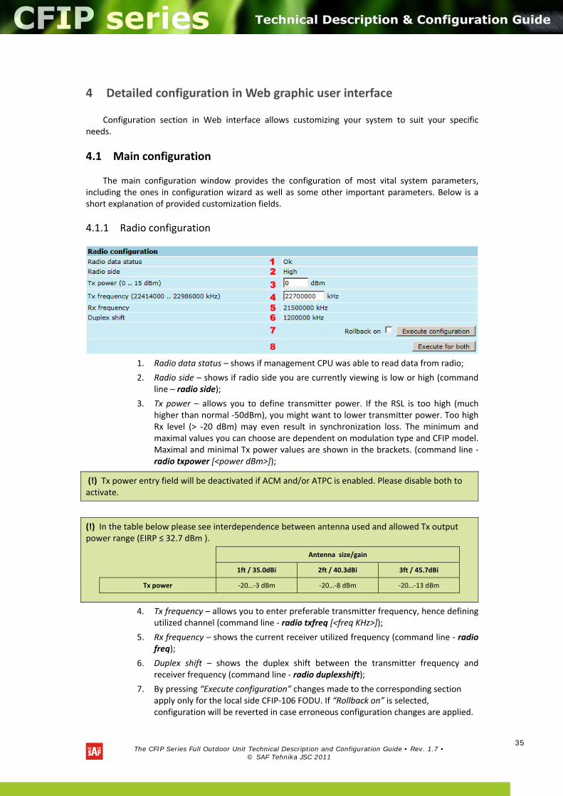
4.1.1 Radio configuration
1. Radio data status – shows if management CPU was able to read data from radio;
2. Radio side – shows if radio side you are currently viewing is low or high (command line – radio side);
3. Tx power – allows you to define transmitter power. If the RSL is too high (much higher than normal ‐50dBm), you might want to lower transmitter power. Too high Rx level (> ‐20 dBm) may even result in synchronization loss. The minimum and maximal values you can choose are dependent on modulation type and CFIP model. Maximal and minimal Tx power values are shown in the brackets. (command line ‐ radio txpower [<power dBm>]);
4. Tx frequency – allows you to enter preferable transmitter frequency, hence defining utilized channel (command line ‐ radio txfreq [<freq KHz>]);
5. Rx frequency – shows the current receiver utilized frequency (command line ‐ radio freq);
6. Duplex shift – shows the duplex shift between the transmitter frequency and receiver frequency (command line ‐ radio duplexshift);
7. By pressing “Execute configuration” changes made to the corresponding section apply only for the local side CFIP‐106 FODU. If “Rollback on” is selected, configuration will be reverted in case erroneous configuration changes are applied.
(!) Tx power entry field will be deactivated if ACM and/or ATPC is enabled. Please disable both to activate.
(!) In the table below please see interdependence between antenna used and allowed Tx output power range (EIRP ≤ 32.7 dBm ).
Antenna size/gain
1ft / 35.0dBi 2ft / 40.3dBi 3ft / 45.7dBi
Tx power ‐20…‐3 dBm ‐20…‐8 dBm ‐20…‐13 dBm
The CFIP Series Full Outdoor Unit Technical Description and Configuration Guide • Rev. 1.7 •
© SAF Tehnika JSC 2011
36
8. Pressing “Execute for both” applies changes made to the corresponding section both for local and remote side CFIP‐106 FODUs.
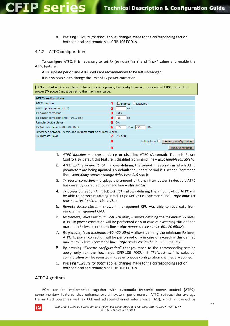
4.1.2 ATPC configuration
To configure ATPC, it is necessary to set Rx (remote) “min” and “max” values and enable the ATPC feature.
ATPC update period and ATPC delta are recommended to be left unchanged.
It is also possible to change the limit of Tx power correction.
1. ATPC function – allows enabling or disabling ATPC (Automatic Transmit Power
Control). By default this feature is disabled (command line – atpc [enable|disable]);
2. ATPC update period (1..5) – allows defining the period in seconds in which ATPC parameters are being updated. By default the update period is 1 second (command line – atpc delay <power change delay time 1..5 sec>);
3. Tx power correction – displays the amount of transmitter power in decibels ATPC has currently corrected (command line – atpc status);
4. Tx power correction limit (‐19..‐1 dB) – allows defining the amount of dB ATPC will be able to correct regarding initial Tx power value (command line – atpc limit <tx power correction limit ‐19..‐1 dB>);
5. Remote device status – shows if management CPU was able to read data from remote management CPU;
6. Rx (remote) level maximum (‐60..‐20 dBm) – allows defining the maximum Rx level. ATPC Tx power correction will be performed only in case of exceeding this defined maximum Rx level (command line – atpc rxmax <rx level max ‐60..‐20 dBm>);
7. Rx (remote) level minimum (‐90..‐50 dBm) – allows defining the minimum Rx level. ATPC Tx power correction will be performed only in case of exceeding this defined maximum Rx level (command line – atpc rxmin <rx level min ‐90..‐50 dBm>);
8. By pressing “Execute configuration” changes made to the corresponding section apply only for the local side CFIP‐106 FODU. If “Rollback on” is selected, configuration will be reverted in case erroneous configuration changes are applied.
9. Pressing “Execute for both” applies changes made to the corresponding section both for local and remote side CFIP‐106 FODUs.
ATPC Algorithm
ACM can be implemented together with automatic transmit power control (ATPC), complimentary features that enhance overall system performance. ATPC reduces the average transmitted power as well as CCI and adjacent‐channel interference (ACI), which is caused by
(!) Note, that ATPC is mechanism for reducing Tx power, that’s why to make proper use of ATPC, transmitter
power (Tx power) must be set to the maximum value.
The CFIP Series Full Outdoor Unit Technical Description and Configuration Guide • Rev. 1.7 •
© SAF Tehnika JSC 2011
37
extraneous power from a signal in an adjacent channel. It also enables a more efficient and cost‐effective network frequency plan and deployment, as well as eliminating some of the receivers’ “upfade” problems by changing the transmitted power according to the link momentary conditions. The lower average Tx power also extends the equipment’s mean time between failures.
ATPC can be used together with ACM to control the transmitted power in any given ACM profile. Different algorithms can be implemented to achieve maximal spectral efficiency or minimal transmitted power using both features in combination. One implementation could target maximal spectral efficacy by trying to reach the highest ACM profile, while the other is willing to compromise on some of the spectral efficiency enabling CCI and ACI reduction. In any chosen algorithm, ATPC reduces the average transmitted power, benefiting each ACM profile and any link condition.
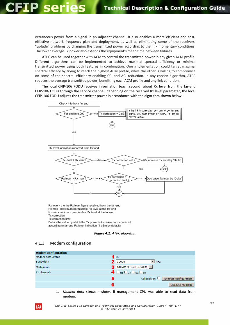
The local CFIP‐106 FODU receives information (each second) about Rx level from the far‐end CFIP‐106 FODU through the service channel; depending on the received Rx level parameter, the local CFIP‐106 FODU adjusts the transmitter power in accordance with the algorithm shown below.
Figure 4.1. ATPC algorithm
4.1.3 Modem configuration
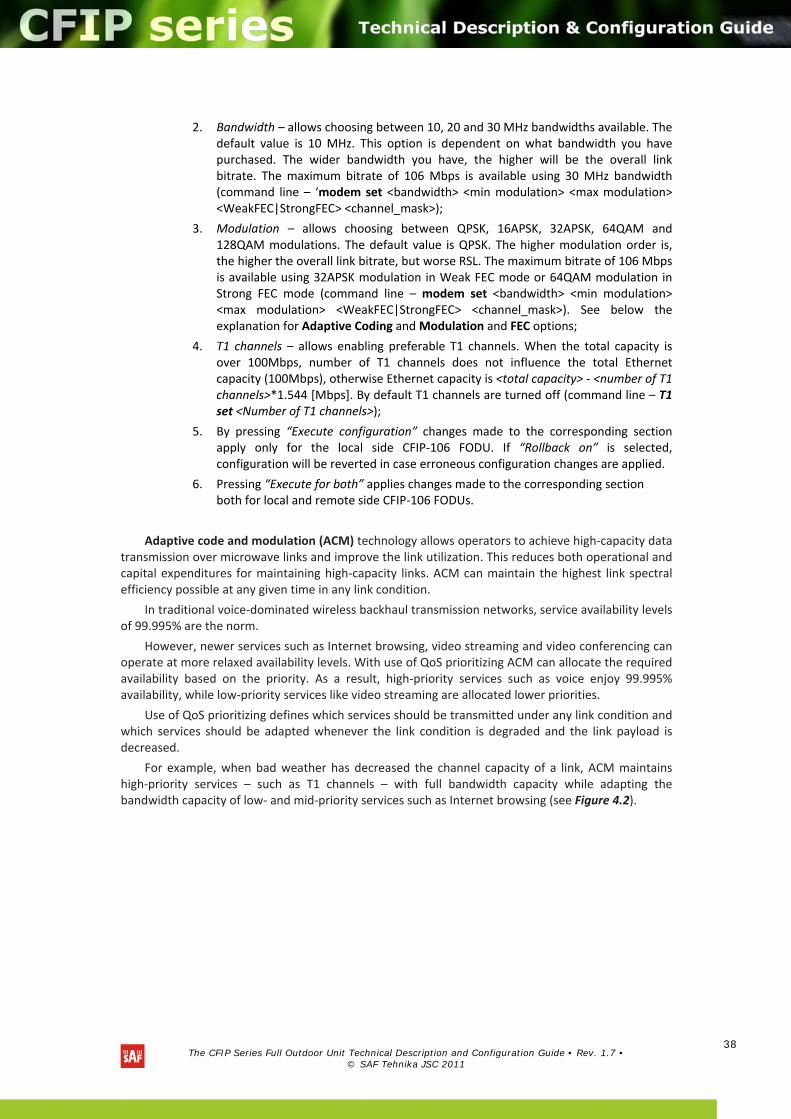
1. Modem data status – shows if management CPU was able to read data from
modem;
The CFIP Series Full Outdoor Unit Technical Description and Configuration Guide • Rev. 1.7 •
© SAF Tehnika JSC 2011
38
2. Bandwidth – allows choosing between 10, 20 and 30 MHz bandwidths available. The default value is 10 MHz. This option is dependent on what bandwidth you have purchased. The wider bandwidth you have, the higher will be the overall link bitrate. The maximum bitrate of 106 Mbps is available using 30 MHz bandwidth (command line – ‘modem set <bandwidth> <min modulation> <max modulation> <WeakFEC|StrongFEC> <channel_mask>);
3. Modulation – allows choosing between QPSK, 16APSK, 32APSK, 64QAM and 128QAM modulations. The default value is QPSK. The higher modulation order is, the higher the overall link bitrate, but worse RSL. The maximum bitrate of 106 Mbps is available using 32APSK modulation in Weak FEC mode or 64QAM modulation in Strong FEC mode (command line – modem set <bandwidth> <min modulation> <max modulation> <WeakFEC|StrongFEC> <channel_mask>). See below the explanation for Adaptive Coding and Modulation and FEC options;
4. T1 channels – allows enabling preferable T1 channels. When the total capacity is over 100Mbps, number of T1 channels does not influence the total Ethernet capacity (100Mbps), otherwise Ethernet capacity is <total capacity> ‐ <number of T1 channels>*1.544 [Mbps]. By default T1 channels are turned off (command line – T1 set <Number of T1 channels>);
5. By pressing “Execute configuration” changes made to the corresponding section apply only for the local side CFIP‐106 FODU. If “Rollback on” is selected, configuration will be reverted in case erroneous configuration changes are applied.
6. Pressing “Execute for both” applies changes made to the corresponding section both for local and remote side CFIP‐106 FODUs.
Adaptive code and modulation (ACM) technology allows operators to achieve high‐capacity data transmission over microwave links and improve the link utilization. This reduces both operational and capital expenditures for maintaining high‐capacity links. ACM can maintain the highest link spectral efficiency possible at any given time in any link condition.
In traditional voice‐dominated wireless backhaul transmission networks, service availability levels of 99.995% are the norm.
However, newer services such as Internet browsing, video streaming and video conferencing can operate at more relaxed availability levels. With use of QoS prioritizing ACM can allocate the required availability based on the priority. As a result, high‐priority services such as voice enjoy 99.995% availability, while low‐priority services like video streaming are allocated lower priorities.
Use of QoS prioritizing defines which services should be transmitted under any link condition and which services should be adapted whenever the link condition is degraded and the link payload is decreased.
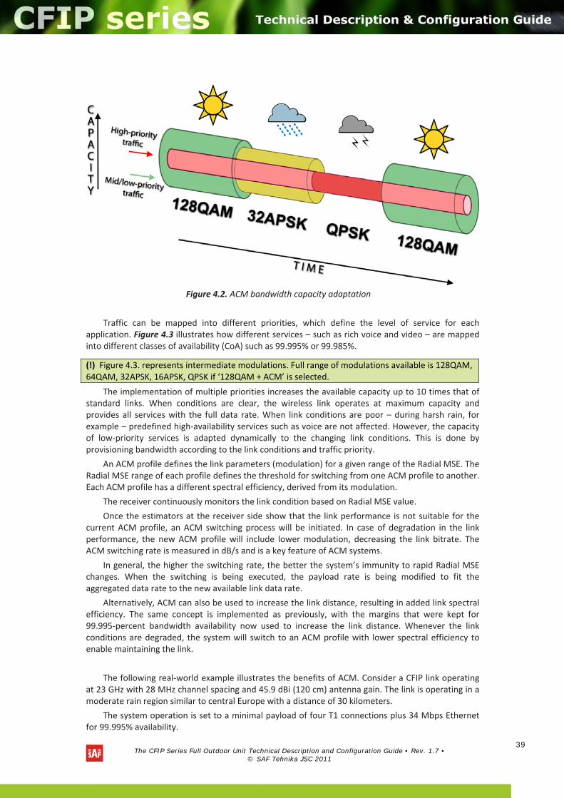
For example, when bad weather has decreased the channel capacity of a link, ACM maintains high‐priority services – such as T1 channels – with full bandwidth capacity while adapting the bandwidth capacity of low‐ and mid‐priority services such as Internet browsing (see Figure 4.2).
The CFIP Series Full Outdoor Unit Technical Description and Configuration Guide • Rev. 1.7 •
© SAF Tehnika JSC 2011
39
Figure 4.2. ACM bandwidth capacity adaptation
Traffic can be mapped into different priorities, which define the level of service for each application. Figure 4.3 illustrates how different services – such as rich voice and video – are mapped into different classes of availability (CoA) such as 99.995% or 99.985%.
The implementation of multiple priorities increases the available capacity up to 10 times that of standard links. When conditions are clear, the wireless link operates at maximum capacity and provides all services with the full data rate. When link conditions are poor – during harsh rain, for example – predefined high‐availability services such as voice are not affected. However, the capacity of low‐priority services is adapted dynamically to the changing link conditions. This is done by provisioning bandwidth according to the link conditions and traffic priority.
An ACM profile defines the link parameters (modulation) for a given range of the Radial MSE. The Radial MSE range of each profile defines the threshold for switching from one ACM profile to another. Each ACM profile has a different spectral efficiency, derived from its modulation.
The receiver continuously monitors the link condition based on Radial MSE value.
Once the estimators at the receiver side show that the link performance is not suitable for the current ACM profile, an ACM switching process will be initiated. In case of degradation in the link performance, the new ACM profile will include lower modulation, decreasing the link bitrate. The ACM switching rate is measured in dB/s and is a key feature of ACM systems.
In general, the higher the switching rate, the better the system’s immunity to rapid Radial MSE changes. When the switching is being executed, the payload rate is being modified to fit the aggregated data rate to the new available link data rate.
Alternatively, ACM can also be used to increase the link distance, resulting in added link spectral efficiency. The same concept is implemented as previously, with the margins that were kept for 99.995‐percent bandwidth availability now used to increase the link distance. Whenever the link conditions are degraded, the system will switch to an ACM profile with lower spectral efficiency to enable maintaining the link.
The following real‐world example illustrates the benefits of ACM. Consider a CFIP link operating at 23 GHz with 28 MHz channel spacing and 45.9 dBi (120 cm) antenna gain. The link is operating in a moderate rain region similar to central Europe with a distance of 30 kilometers.
The system operation is set to a minimal payload of four T1 connections plus 34 Mbps Ethernet for 99.995% availability.
(!) Figure 4.3. represents intermediate modulations. Full range of modulations available is 128QAM, 64QAM, 32APSK, 16APSK, QPSK if ‘128QAM + ACM’ is selected.
The CFIP Series Full Outdoor Unit Technical Description and Configuration Guide • Rev. 1.7 •
© SAF Tehnika JSC 2011
40
Using the new ACM technology, the system was able to operate most of the time at 106 Mbps, depending on the link conditions.
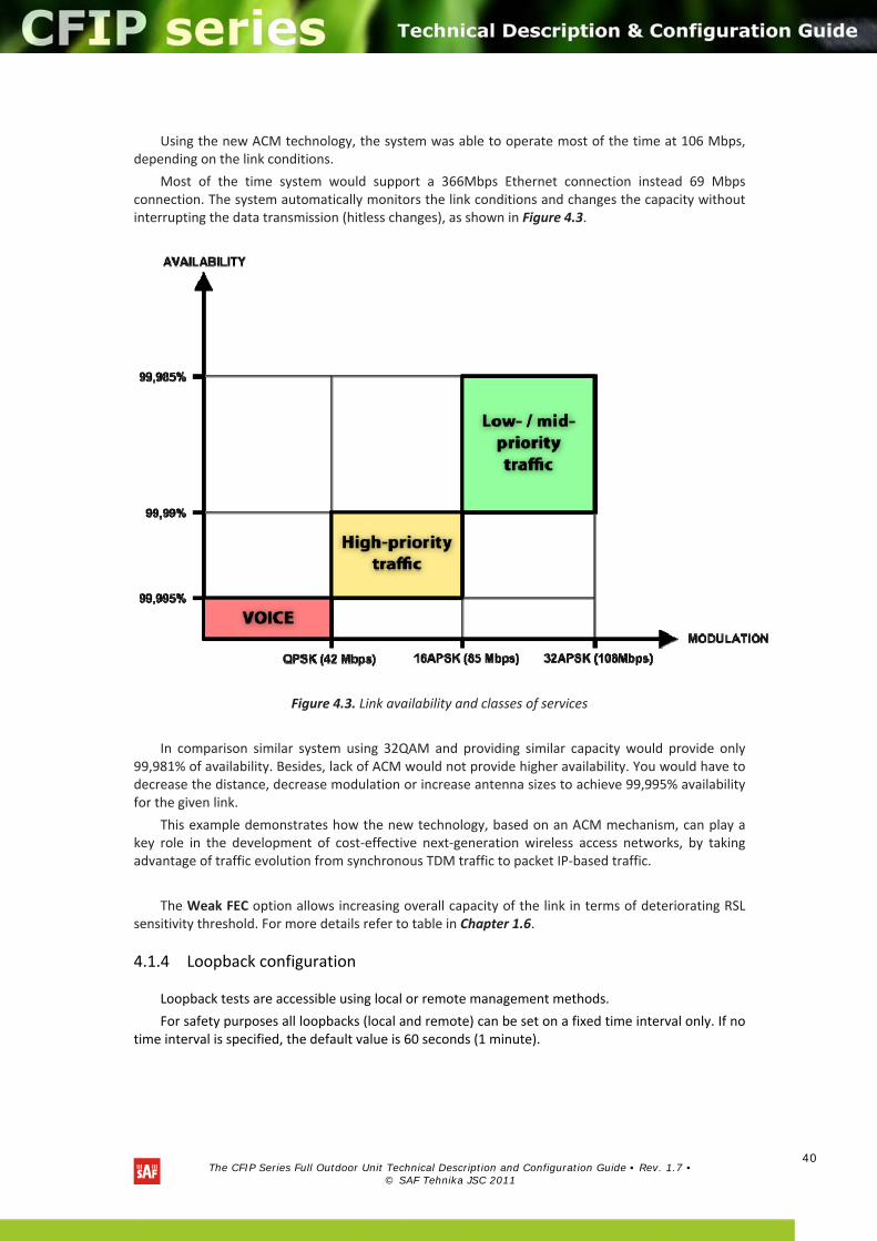
Most of the time system would support a 366Mbps Ethernet connection instead 69 Mbps connection. The system automatically monitors the link conditions and changes the capacity without interrupting the data transmission (hitless changes), as shown in Figure 4.3.
Figure 4.3. Link availability and classes of services
In comparison similar system using 32QAM and providing similar capacity would provide only 99,981% of availability. Besides, lack of ACM would not provide higher availability. You would have to decrease the distance, decrease modulation or increase antenna sizes to achieve 99,995% availability for the given link.
This example demonstrates how the new technology, based on an ACM mechanism, can play a key role in the development of cost‐effective next‐generation wireless access networks, by taking advantage of traffic evolution from synchronous TDM traffic to packet IP‐based traffic.
The Weak FEC option allows increasing overall capacity of the link in terms of deteriorating RSL sensitivity threshold. For more details refer to table in Chapter 1.6.
4.1.4 Loopback configuration
Loopback tests are accessible using local or remote management methods.
For safety purposes all loopbacks (local and remote) can be set on a fixed time interval only. If no time interval is specified, the default value is 60 seconds (1 minute).
The CFIP Series Full Outdoor Unit Technical Description and Configuration Guide • Rev. 1.7 •
© SAF Tehnika JSC 2011
41
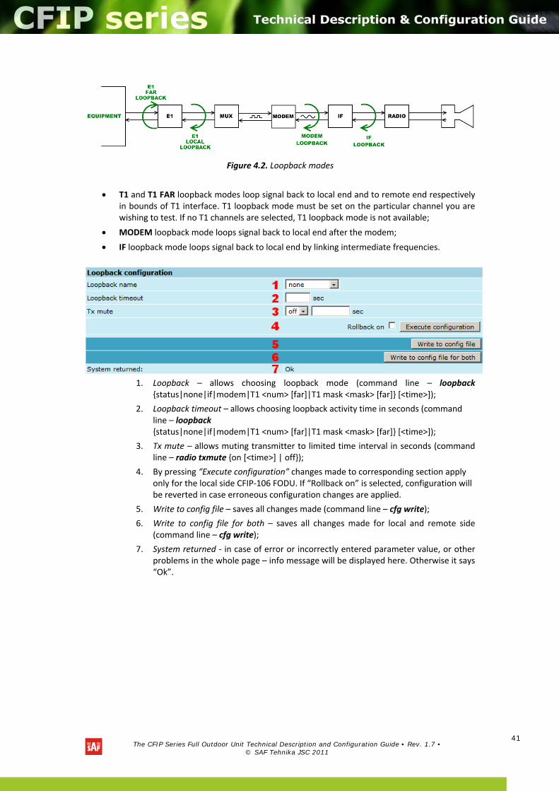
Figure 4.2. Loopback modes
T1 and T1 FAR loopback modes loop signal back to local end and to remote end respectively in bounds of T1 interface. T1 loopback mode must be set on the particular channel you are wishing to test. If no T1 channels are selected, T1 loopback mode is not available;
MODEM loopback mode loops signal back to local end after the modem;
IF loopback mode loops signal back to local end by linking intermediate frequencies.
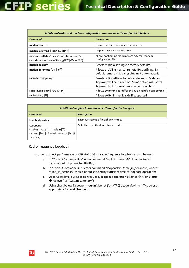
1. Loopback – allows choosing loopback mode (command line – loopback
status|none|if|modem|T1 <num> [far]|T1 mask <mask> [far] [<time>]);
2. Loopback timeout – allows choosing loopback activity time in seconds (command line – loopback status|none|if|modem|T1 <num> [far]|T1 mask <mask> [far] [<time>]);
3. Tx mute – allows muting transmitter to limited time interval in seconds (command line – radio txmute on [<time>] | off);
4. By pressing “Execute configuration” changes made to corresponding section apply only for the local side CFIP‐106 FODU. If “Rollback on” is selected, configuration will be reverted in case erroneous configuration changes are applied.
5. Write to config file – saves all changes made (command line – cfg write);
6. Write to config file for both – saves all changes made for local and remote side (command line – cfg write);
7. System returned ‐ in case of error or incorrectly entered parameter value, or other problems in the whole page – info message will be displayed here. Otherwise it says “Ok”.
The CFIP Series Full Outdoor Unit Technical Description and Configuration Guide • Rev. 1.7 •
© SAF Tehnika JSC 2011
42
Radio frequency loopback
In order to check performance of CFIP‐106 24GHz, radio frequency loopback should be used:
a. In “ToolsCommand line” enter command “radio txpower ‐10” in order to set transmit output power to ‐10 dBm;
b. In “ToolsCommand line” enter command “loopback rf <time_in_second>”, where” <time_in_seconds> should be substituted by sufficient time of loopback operation;
c. Observe Rx level during radio frequency loopback operation (“Status Main status” Rx level” or “System summary”)
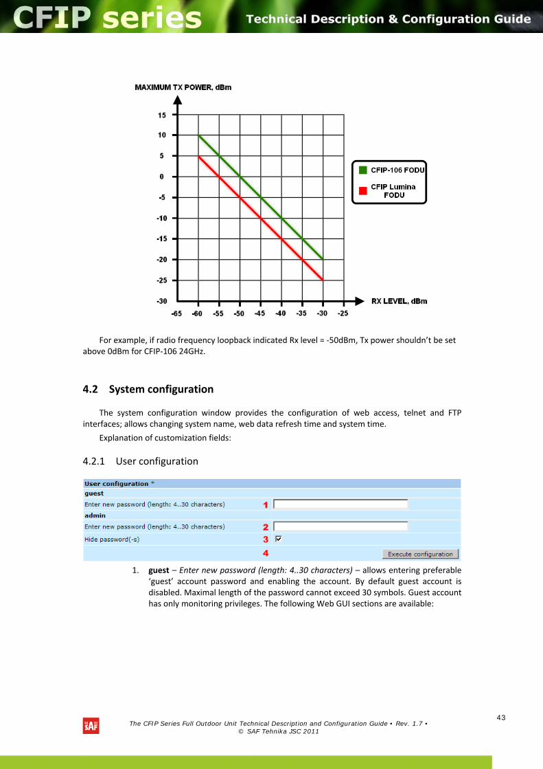
d. Using chart below Tx power shouldn’t be set (for ATPC) above Maximum Tx power at appropriate Rx level observed:
Additional radio and modem configuration commands in Telnet/serial interface
Command Description
modem status Shows the status of modem parameters
modem allowed [<bandwidth>] Displays available modulations
modem setfile <file> <modulation min>
<modulation max> StrongFEC|WeakFEC
Allows configuring modem from external modem configuration file
modem factory Resets modem settings to factory defaults.
modem ipremote [on | off] Allows enabling manual remote IP specifying. By default remote IP is being obtained automatically.
radio factory [max] Resets radio settings to factory defaults. By default Tx power will be turned off. ‘max’ option will switch Tx power to the maximum value after restart.
radio duplexshift [<DS KHz>] Allows switching to different duplexshift if supported
radio side [L|H] Allows switching radio side if supported
Additional loopback commands in Telnet/serial interface
Command Description
Loopback status Displays status of loopback mode.
Loopback status|none|if|modem|T1 <num> [far]|T1 mask <mask> [far] [<time>]
Sets the specified loopback mode.
The CFIP Series Full Outdoor Unit Technical Description and Configuration Guide • Rev. 1.7 •
© SAF Tehnika JSC 2011
43
For example, if radio frequency loopback indicated Rx level = ‐50dBm, Tx power shouldn’t be set above 0dBm for CFIP‐106 24GHz.
4.2 System configuration
The system configuration window provides the configuration of web access, telnet and FTP interfaces; allows changing system name, web data refresh time and system time.
Explanation of customization fields:
4.2.1 User configuration
1. guest – Enter new password (length: 4..30 characters) – allows entering preferable
‘guest’ account password and enabling the account. By default guest account is disabled. Maximal length of the password cannot exceed 30 symbols. Guest account has only monitoring privileges. The following Web GUI sections are available:
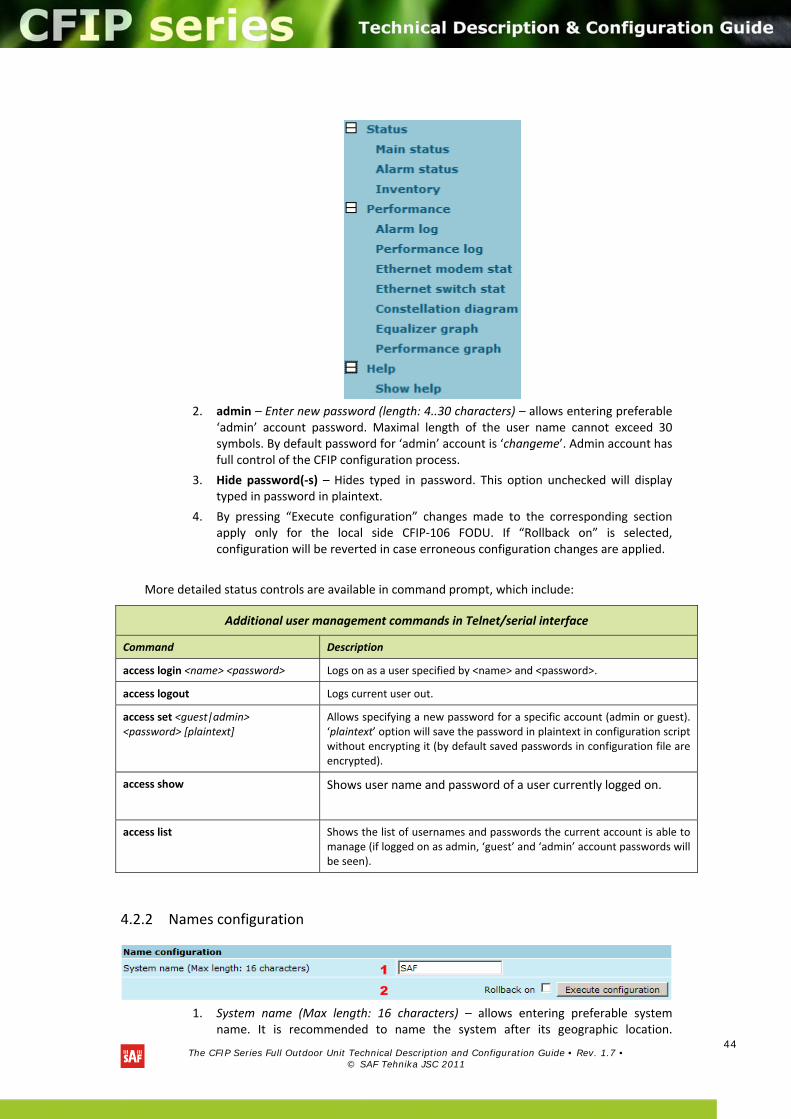
The CFIP Series Full Outdoor Unit Technical Description and Configuration Guide • Rev. 1.7 •
© SAF Tehnika JSC 2011
44
2. admin – Enter new password (length: 4..30 characters) – allows entering preferable
‘admin’ account password. Maximal length of the user name cannot exceed 30 symbols. By default password for ‘admin’ account is ‘changeme’. Admin account has full control of the CFIP configuration process.
3. Hide password(‐s) – Hides typed in password. This option unchecked will display typed in password in plaintext.
4. By pressing “Execute configuration” changes made to the corresponding section apply only for the local side CFIP‐106 FODU. If “Rollback on” is selected, configuration will be reverted in case erroneous configuration changes are applied.
More detailed status controls are available in command prompt, which include:
4.2.2 Names configuration
1. System name (Max length: 16 characters) – allows entering preferable system name. It is recommended to name the system after its geographic location.
Additional user management commands in Telnet/serial interface
Command Description
access login <name> <password> Logs on as a user specified by <name> and <password>.
access logout Logs current user out.
access set <guest|admin> <password> [plaintext]
Allows specifying a new password for a specific account (admin or guest). ‘plaintext’ option will save the password in plaintext in configuration script without encrypting it (by default saved passwords in configuration file are encrypted).
access show Shows user name and password of a user currently logged on.
access list Shows the list of usernames and passwords the current account is able to manage (if logged on as admin, ‘guest’ and ‘admin’ account passwords will be seen).
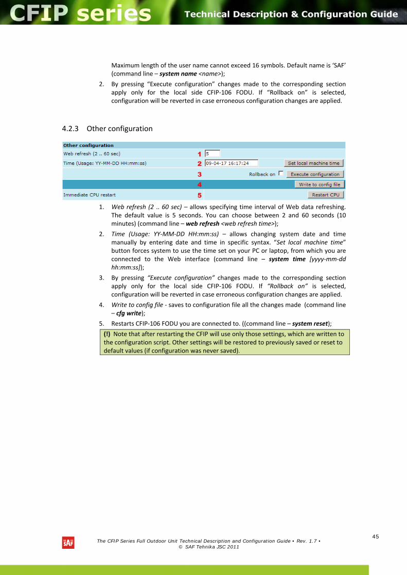
The CFIP Series Full Outdoor Unit Technical Description and Configuration Guide • Rev. 1.7 •
© SAF Tehnika JSC 2011
45
Maximum length of the user name cannot exceed 16 symbols. Default name is ‘SAF’ (command line – system name <name>);
2. By pressing “Execute configuration” changes made to the corresponding section apply only for the local side CFIP‐106 FODU. If “Rollback on” is selected, configuration will be reverted in case erroneous configuration changes are applied.
4.2.3 Other configuration
1. Web refresh (2 .. 60 sec) – allows specifying time interval of Web data refreshing. The default value is 5 seconds. You can choose between 2 and 60 seconds (10 minutes) (command line – web refresh <web refresh time>);
2. Time (Usage: YY‐MM‐DD HH:mm:ss) – allows changing system date and time manually by entering date and time in specific syntax. “Set local machine time” button forces system to use the time set on your PC or laptop, from which you are connected to the Web interface (command line – system time [yyyy‐mm‐dd hh:mm:ss]);
3. By pressing “Execute configuration” changes made to the corresponding section apply only for the local side CFIP‐106 FODU. If “Rollback on” is selected, configuration will be reverted in case erroneous configuration changes are applied.
4. Write to config file ‐ saves to configuration file all the changes made (command line – cfg write);
5. Restarts CFIP‐106 FODU you are connected to. ((command line – system reset);
(!) Note that after restarting the CFIP will use only those settings, which are written to the configuration script. Other settings will be restored to previously saved or reset to default values (if configuration was never saved).
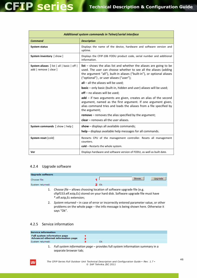
The CFIP Series Full Outdoor Unit Technical Description and Configuration Guide • Rev. 1.7 •
© SAF Tehnika JSC 2011
46
4.2.4 Upgrade software
1. Choose file – allows choosing location of software upgrade file (e.g. cfipf153.elf.ezip,Ec) stored on your hard disk. Software upgrade file must have *.elf.ezip,Ec extension;
2. System returned – in case of error or incorrectly entered parameter value, or other problems on the whole page – the info message is being shown here. Otherwise it says “Ok”.
4.2.5 Service information
1. Full system information page – provides full system information summary in a
separate browser tab;
Additional system commands in Telnet/serial interface
Command Description
System status Displays the name of the device, hardware and software version and uptime.
System inventory [ show ] Displays the CFIP‐106 FODU product code, serial number and additional information.
System aliases [ list | all | basic | off | add | remove | clear ]
list – shows the alias list and whether the aliases are going to be used. The user can choose whether to see all the aliases (adding the argument “all”), built‐in aliases (“built‐in”), or optional aliases (“optional”) , or user aliases (“user”);
all – all the aliases will be used;
basic – only basic (built‐in, hidden and user) aliases will be used;
off – no aliases will be used;
add – if two arguments are given, creates an alias of the second argument, named as the first argument. If one argument given, alias command tries and loads the aliases from a file specified by the argument;
remove – removes the alias specified by the argument;
clear – removes all the user aliases.
System commands [ show | help ] show – displays all available commands;
help – displays available help messages for all commands.
System reset [cold] Restarts CPU of the management controller. Resets all management counters.
cold – Restarts the whole system.
Ver Displays hardware and software version of FODU, as well as built date.
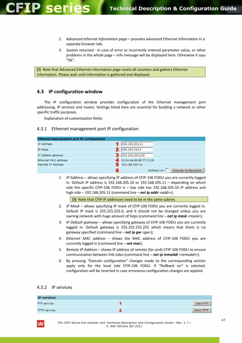
The CFIP Series Full Outdoor Unit Technical Description and Configuration Guide • Rev. 1.7 •
© SAF Tehnika JSC 2011
47
2. Advanced ethernet information page – provides advanced Ethernet information in a separate browser tab;
3. System returned ‐ in case of error or incorrectly entered parameter value, or other problems in the whole page – info message will be displayed here. Otherwise it says “Ok”.
4.3 IP configuration window
The IP configuration window provides configuration of the Ethernet management port addressing, IP services and routes. Settings listed here are essential for building a network or other specific traffic purposes.
Explanation of customization fields:
4.3.1 Ethernet management port IP configuration
1. IP Address – allows specifying IP address of CFIP‐106 FODU you are currently logged in. Default IP address is 192.168.205.10 or 192.168.205.11 – depending on which side the specific CFIP‐106 FODU is – low side has 192.168.205.10 IP address and high side – 192.168.205.11 (command line – net ip addr <addr>);
2. IP Mask – allows specifying IP mask of CFIP‐106 FODU you are currently logged in. Default IP mask is 255.255.255.0, and it should not be changed unless you are owning network with huge amount of hops (command line – net ip mask <mask>);
3. IP Default gateway – allows specifying gateway of CFIP‐106 FODU you are currently logged in. Default gateway is 255.255.255.255 which means that there is no gateway specified (command line – net ip gw <gw>);
4. Ethernet MAC address – shows the MAC address of CFIP‐106 FODU you are currently logged in (command line – net mac);
5. Remote IP Address – shows IP address of remote (far‐end) CFIP‐106 FODU to ensure communication between link sides (command line – net ip remaddr <remaddr>);
6. By pressing “Execute configuration” changes made to the corresponding section apply only for the local side CFIP‐106 FODU. If “Rollback on” is selected, configuration will be reverted in case erroneous configuration changes are applied.
4.3.2 IP services
(!) Note that Advanced Ethernet information page resets all counters and gathers Ethernet information. Please wait until information is gathered and displayed.
(!) Note that CFIP IP addresses need to be in the same subnet.

The CFIP Series Full Outdoor Unit Technical Description and Configuration Guide • Rev. 1.7 •
© SAF Tehnika JSC 2011
48
1. FTP service – starts FTP service for file access and software update of your CFIP‐106 FODU. By default FTP service is not running (command line – net start ftp);
2. TFTP service – starts TFTP service for file transfer between both CFIP‐106 FODU link sides. By default TFTP service is not running (command line – net start tftp).
4.3.3 Static route configuration
1. Static routes – shows the list of existing static routes, as well as allows you to
choose specific route you are willing to change or delete. By default there is one route which depends on earlier entered IP settings (command line – net route);
2. Network address – allows specifying network address for the route changing/adding (command line – net route add|delete <dest addr> [MASK <mask>] <gateway>);
3. Network mask ‐ allows specifying network mask for changing/adding the route (command line – net route add|delete <dest addr> [MASK <mask>] <gateway>);
4. Gateway ‐ allows specifying gateway for the route changing/adding (command line – net route add|delete <dest addr> [MASK <mask>] <gateway>);
5. After entering addresses or selecting a specific route, buttons “Add”, “Change” and “Delete” allow you to modify CFIP‐106 FODU routes. If “Rollback on” is selected, configuration will be reverted in case of erroneous configuration changes applied.
6. Write to config file ‐ saves to configuration file all the changes made (command line – cfg write);
7. System returned ‐ in case of error or incorrectly entered parameter value, or other problems on the whole page – the info message is being shown here. Otherwise it says “Ok”.
(!) Do not make any changes to default route; otherwise, management connection to CFIP will be lost.
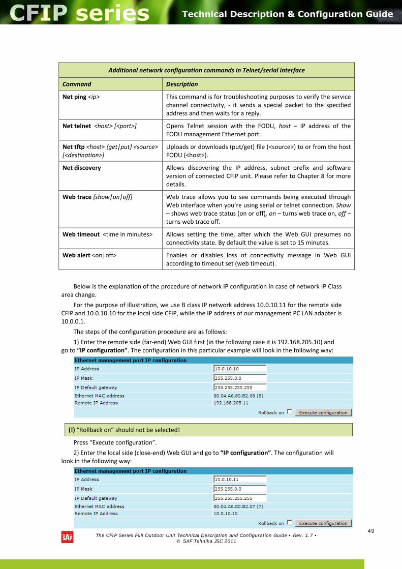
The CFIP Series Full Outdoor Unit Technical Description and Configuration Guide • Rev. 1.7 •
© SAF Tehnika JSC 2011
49
Below is the explanation of the procedure of network IP configuration in case of network IP Class area change.
For the purpose of illustration, we use B class IP network address 10.0.10.11 for the remote side CFIP and 10.0.10.10 for the local side CFIP, while the IP address of our management PC LAN adapter is 10.0.0.1.
The steps of the configuration procedure are as follows:
1) Enter the remote side (far‐end) Web GUI first (in the following case it is 192.168.205.10) and go to “IP configuration”. The configuration in this particular example will look in the following way:
Press “Execute configuration”.
2) Enter the local side (close‐end) Web GUI and go to “IP configuration”. The configuration will look in the following way:
Additional network configuration commands in Telnet/serial interface
Command Description
Net ping <ip> This command is for troubleshooting purposes to verify the service channel connectivity, ‐ it sends a special packet to the specified address and then waits for a reply.
Net telnet <host> [<port>] Opens Telnet session with the FODU, host – IP address of the FODU management Ethernet port.
Net tftp <host> get|put <source> [<destination>]
Uploads or downloads (put/get) file (<source>) to or from the host FODU (<host>).
Net discovery Allows discovering the IP address, subnet prefix and software version of connected CFIP unit. Please refer to Chapter 8 for more details.
Web trace show|on|off Web trace allows you to see commands being executed through Web interface when you’re using serial or telnet connection. Show – shows web trace status (on or off), on – turns web trace on, off – turns web trace off.
Web timeout <time in minutes> Allows setting the time, after which the Web GUI presumes no connectivity state. By default the value is set to 15 minutes.
Web alert <on|off> Enables or disables loss of connectivity message in Web GUI according to timeout set (web timeout).
(!) “Rollback on” should not be selected!
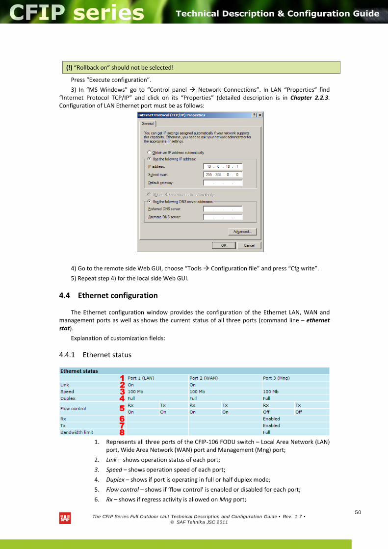
The CFIP Series Full Outdoor Unit Technical Description and Configuration Guide • Rev. 1.7 •
© SAF Tehnika JSC 2011
50
Press “Execute configuration”.
3) In “MS Windows” go to “Control panel Network Connections”. In LAN “Properties” find “Internet Protocol TCP/IP” and click on its “Properties” (detailed description is in Chapter 2.2.3. Configuration of LAN Ethernet port must be as follows:
4) Go to the remote side Web GUI, choose “Tools Configuration file” and press “Cfg write”.
5) Repeat step 4) for the local side Web GUI.
4.4 Ethernet configuration
The Ethernet configuration window provides the configuration of the Ethernet LAN, WAN and management ports as well as shows the current status of all three ports (command line – ethernet stat).
Explanation of customization fields:
4.4.1 Ethernet status
1. Represents all three ports of the CFIP‐106 FODU switch – Local Area Network (LAN) port, Wide Area Network (WAN) port and Management (Mng) port;
2. Link – shows operation status of each port;
3. Speed – shows operation speed of each port;
4. Duplex – shows if port is operating in full or half duplex mode;
5. Flow control – shows if ‘flow control’ is enabled or disabled for each port;
6. Rx – shows if regress activity is allowed on Mng port;
(!) “Rollback on” should not be selected!
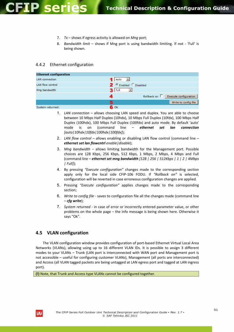
The CFIP Series Full Outdoor Unit Technical Description and Configuration Guide • Rev. 1.7 •
© SAF Tehnika JSC 2011
51
7. Tx – shows if egress activity is allowed on Mng port;
8. Bandwidth limit – shows if Mng port is using bandwidth limiting. If not ‐ 'Full' is being shown.
4.4.2 Ethernet configuration
1. LAN connection – allows choosing LAN speed and duplex. You are able to choose between 10 Mbps Half Duplex (10hdx), 10 Mbps Full Duplex (10fdx), 100 Mbps Half Duplex (100hdx), 100 Mbps Full Duplex (100fdx) and auto mode. By default ‘auto’ mode is on (command line – ethernet set lan connection [auto|10hdx|10fdx|100hdx|100fdx]);
2. LAN flow control – allows enabling or disabling LAN flow control (command line – ethernet set lan flowcntrl enable|disable);
3. Mng bandwidth – allows limiting bandwidth for the Management port. Possible choices are 128 Kbps, 256 Kbps, 512 Kbps, 1 Mbps, 2 Mbps, 4 Mbps and Full (command line – ethernet set mng bandwidth [128 | 256 | 512Kbps | 1 | 2 | 4Mbps | Full]);
4. By pressing “Execute configuration” changes made to the corresponding section apply only for the local side CFIP‐106 FODU. If “Rollback on” is selected, configuration will be reverted in case erroneous configuration changes are applied.
5. Pressing “Execute configuration” applies changes made to the corresponding section;
6. Write to config file ‐ saves to configuration file all the changes made (command line – cfg write);
7. System returned ‐ in case of error or incorrectly entered parameter value, or other problems on the whole page – the info message is being shown here. Otherwise it says “Ok”.
4.5 VLAN configuration
The VLAN configuration window provides configuration of port‐based Ethernet Virtual Local Area Networks (VLANs), allowing using up to 16 different VLAN IDs. It is possible to assign 3 different modes to your VLANs – Trunk (LAN port is interconnected with WAN port and Management port is not accessible – useful for configuring customer VLANs), Management (all ports are interconnected) and Access (all VLAN tagged packets are being untagged at LAN egress port and tagged at LAN ingress port).
(!) Note, that Trunk and Access type VLANs cannot be configured together.
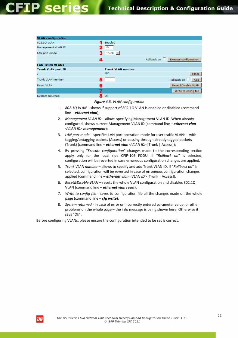
The CFIP Series Full Outdoor Unit Technical Description and Configuration Guide • Rev. 1.7 •
© SAF Tehnika JSC 2011
52
Figure 4.3. VLAN configuration
1. 802.1Q VLAN – shows if support of 802.1Q VLAN is enabled or disabled (command line – ethernet vlan);
2. Management VLAN ID – allows specifying Management VLAN ID. When already configured, shows current Management VLAN ID (command line – ethernet vlan <VLAN ID> management);
3. LAN port mode – specifies LAN port operation mode for user traffic VLANs – with tagging/untagging packets (Access) or passing through already tagged packets (Trunk) (command line – ethernet vlan <VLAN ID> [Trunk | Access]);
4. By pressing “Execute configuration” changes made to the corresponding section apply only for the local side CFIP‐106 FODU. If “Rollback on” is selected, configuration will be reverted in case erroneous configuration changes are applied.
5. Trunk VLAN number – allows to specify and add Trunk VLAN ID. If “Rollback on” is selected, configuration will be reverted in case of erroneous configuration changes applied (command line – ethernet vlan <VLAN ID> [Trunk | Access]);
6. Reset&Disable VLAN – resets the whole VLAN configuration and disables 802.1Q VLAN (command line – ethernet vlan reset);
7. Write to config file ‐ saves to configuration file all the changes made on the whole page (command line – cfg write);
8. System returned ‐ in case of error or incorrectly entered parameter value, or other problems on the whole page – the info message is being shown here. Otherwise it says “Ok”.
Before configuring VLANs, please ensure the configuration intended to be set is correct.
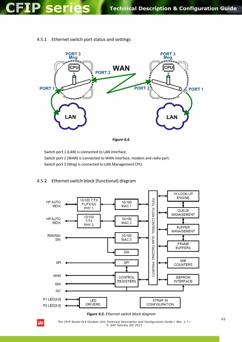
The CFIP Series Full Outdoor Unit Technical Description and Configuration Guide • Rev. 1.7 •
© SAF Tehnika JSC 2011
53
4.5.1 Ethernet switch port status and settings
Figure 4.4.
Switch port 1 (LAN) is connected to LAN interface.
Switch port 2 (WAN) is connected to WAN interface, modem and radio part.
Switch port 3 (Mng) is connected to LAN Management CPU.
4.5.2 Ethernet switch block (functional) diagram
Figure 4.5. Ethernet switch block diagram
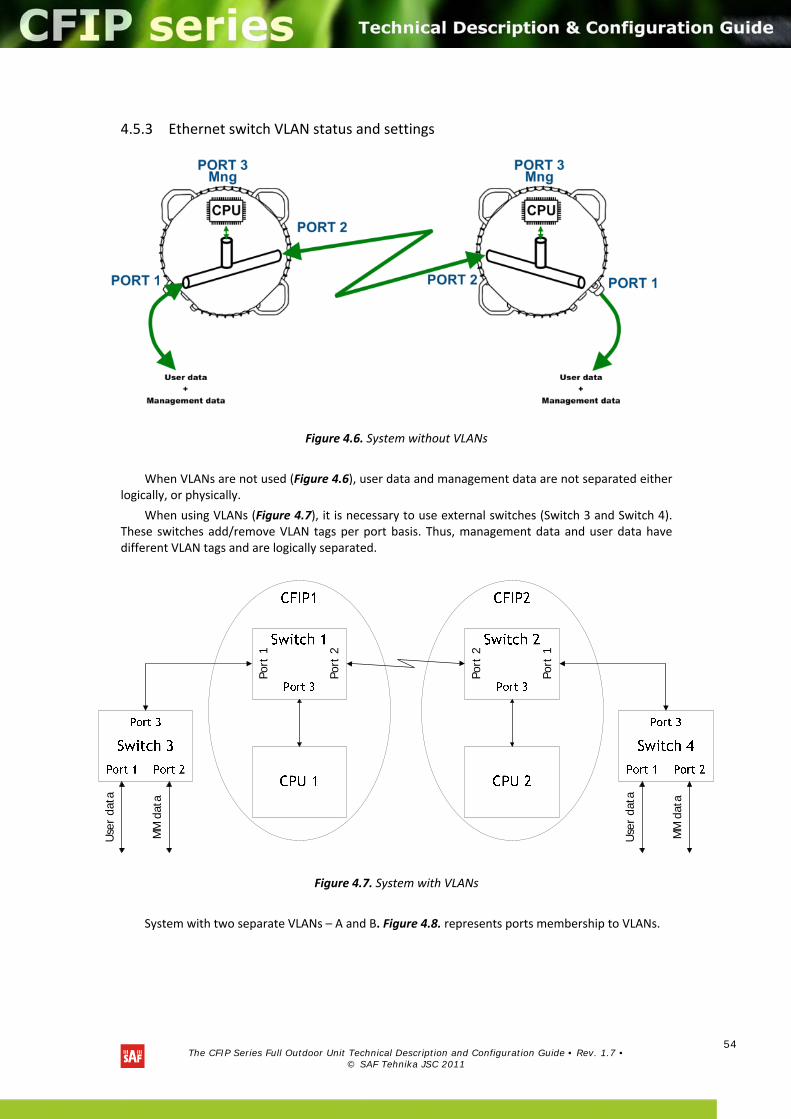
The CFIP Series Full Outdoor Unit Technical Description and Configuration Guide • Rev. 1.7 •
© SAF Tehnika JSC 2011
54
4.5.3 Ethernet switch VLAN status and settings
Figure 4.6. System without VLANs
When VLANs are not used (Figure 4.6), user data and management data are not separated either logically, or physically.
When using VLANs (Figure 4.7), it is necessary to use external switches (Switch 3 and Switch 4). These switches add/remove VLAN tags per port basis. Thus, management data and user data have different VLAN tags and are logically separated.
Use
r da
ta
MM
dat
a
Use
r da
ta
MM
dat
a
Port
1
Port
1
Port
2
Port
2
Figure 4.7. System with VLANs
System with two separate VLANs – A and B. Figure 4.8. represents ports membership to VLANs.
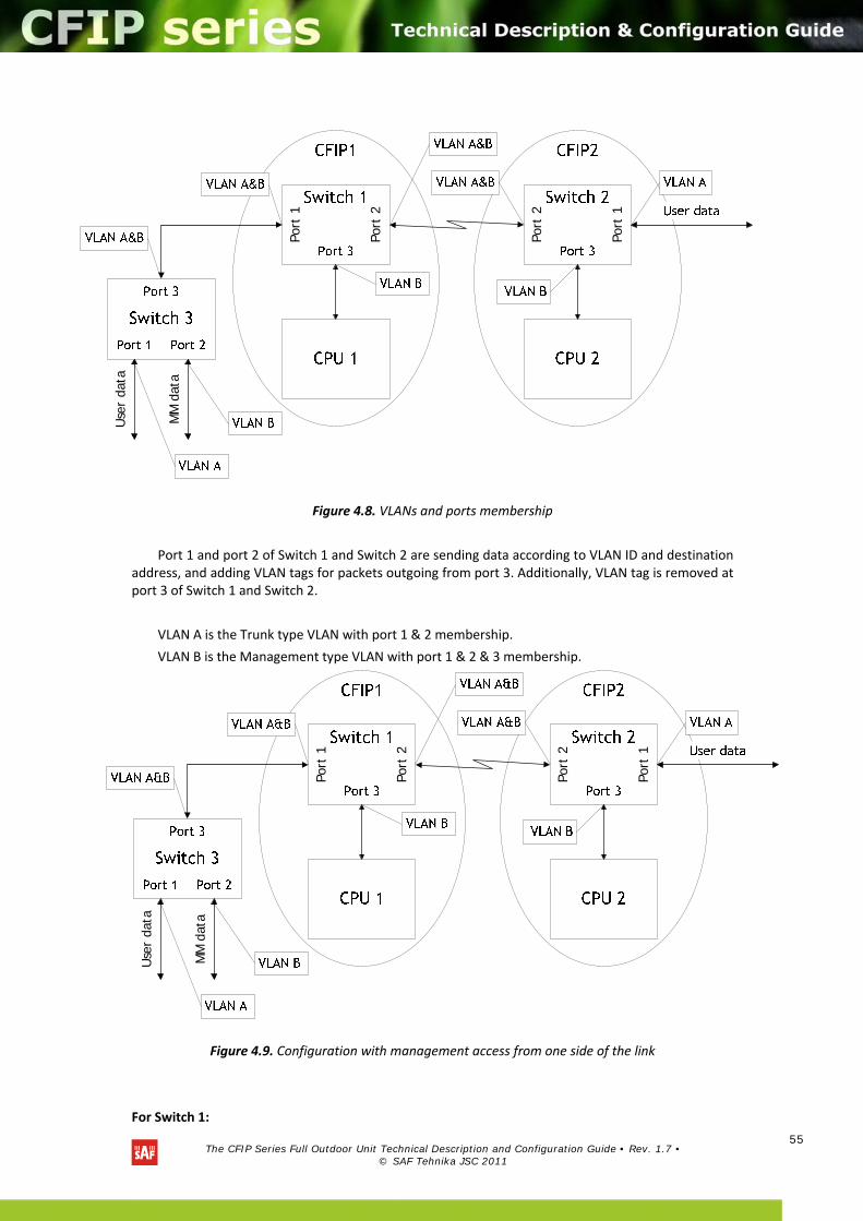
The CFIP Series Full Outdoor Unit Technical Description and Configuration Guide • Rev. 1.7 •
© SAF Tehnika JSC 2011
55
Use
r da
ta
MM
dat
a
Port
1
Port
1
Port
2
Port
2
Figure 4.8. VLANs and ports membership
Port 1 and port 2 of Switch 1 and Switch 2 are sending data according to VLAN ID and destination address, and adding VLAN tags for packets outgoing from port 3. Additionally, VLAN tag is removed at port 3 of Switch 1 and Switch 2.
VLAN A is the Trunk type VLAN with port 1 & 2 membership.
VLAN B is the Management type VLAN with port 1 & 2 & 3 membership.
Use
r da
ta
MM
dat
a
Port
1
Port
1
Port
2
Port
2
Figure 4.9. Configuration with management access from one side of the link
For Switch 1:
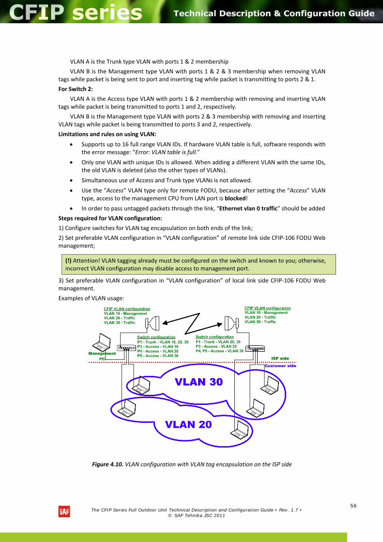
The CFIP Series Full Outdoor Unit Technical Description and Configuration Guide • Rev. 1.7 •
© SAF Tehnika JSC 2011
56
VLAN A is the Trunk type VLAN with ports 1 & 2 membership
VLAN B is the Management type VLAN with ports 1 & 2 & 3 membership when removing VLAN tags while packet is being sent to port and inserting tag while packet is transmitting to ports 2 & 1.
For Switch 2:
VLAN A is the Access type VLAN with ports 1 & 2 membership with removing and inserting VLAN tags while packet is being transmitted to ports 1 and 2, respectively.
VLAN B is the Management type VLAN with ports 2 & 3 membership with removing and inserting VLAN tags while packet is being transmitted to ports 3 and 2, respectively.
Limitations and rules on using VLAN:
Supports up to 16 full range VLAN IDs. If hardware VLAN table is full, software responds with the error message: “Error: VLAN table is full.”
Only one VLAN with unique IDs is allowed. When adding a different VLAN with the same IDs, the old VLAN is deleted (also the other types of VLANs).
Simultaneous use of Access and Trunk type VLANs is not allowed.
Use the “Access” VLAN type only for remote FODU, because after setting the “Access” VLAN type, access to the management CPU from LAN port is blocked!
In order to pass untagged packets through the link, “Ethernet vlan 0 traffic” should be added
Steps required for VLAN configuration:
1) Configure switches for VLAN tag encapsulation on both ends of the link;
2) Set preferable VLAN configuration in “VLAN configuration” of remote link side CFIP‐106 FODU Web management;
3) Set preferable VLAN configuration in “VLAN configuration” of local link side CFIP‐106 FODU Web management.
Examples of VLAN usage:
Figure 4.10. VLAN configuration with VLAN tag encapsulation on the ISP side
(!) Attention! VLAN tagging already must be configured on the switch and known to you; otherwise, incorrect VLAN configuration may disable access to management port.
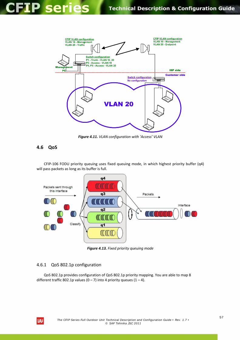
The CFIP Series Full Outdoor Unit Technical Description and Configuration Guide • Rev. 1.7 •
© SAF Tehnika JSC 2011
57
Figure 4.11. VLAN configuration with ‘Access’ VLAN
4.6 QoS
CFIP‐106 FODU priority queuing uses fixed queuing mode, in which highest priority buffer (q4) will pass packets as long as its buffer is full.
Figure 4.13. Fixed priority queuing mode
4.6.1 QoS 802.1p configuration
QoS 802.1p provides configuration of QoS 802.1p priority mapping. You are able to map 8 different traffic 802.1p values (0 – 7) into 4 priority queues (1 – 4).
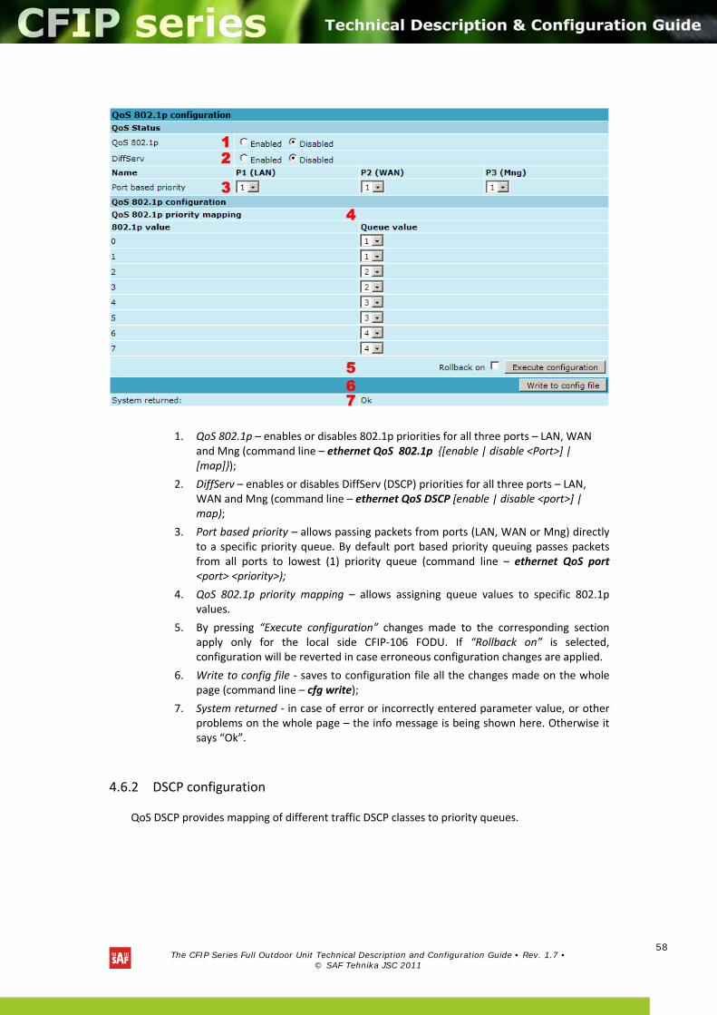
The CFIP Series Full Outdoor Unit Technical Description and Configuration Guide • Rev. 1.7 •
© SAF Tehnika JSC 2011
58
1. QoS 802.1p – enables or disables 802.1p priorities for all three ports – LAN, WAN and Mng (command line – ethernet QoS 802.1p [enable | disable <Port>] | [map]);
2. DiffServ – enables or disables DiffServ (DSCP) priorities for all three ports – LAN, WAN and Mng (command line – ethernet QoS DSCP [enable | disable <port>] | map);
3. Port based priority – allows passing packets from ports (LAN, WAN or Mng) directly to a specific priority queue. By default port based priority queuing passes packets from all ports to lowest (1) priority queue (command line – ethernet QoS port <port> <priority>);
4. QoS 802.1p priority mapping – allows assigning queue values to specific 802.1p values.
5. By pressing “Execute configuration” changes made to the corresponding section apply only for the local side CFIP‐106 FODU. If “Rollback on” is selected, configuration will be reverted in case erroneous configuration changes are applied.
6. Write to config file ‐ saves to configuration file all the changes made on the whole page (command line – cfg write);
7. System returned ‐ in case of error or incorrectly entered parameter value, or other problems on the whole page – the info message is being shown here. Otherwise it says “Ok”.
4.6.2 DSCP configuration
QoS DSCP provides mapping of different traffic DSCP classes to priority queues.
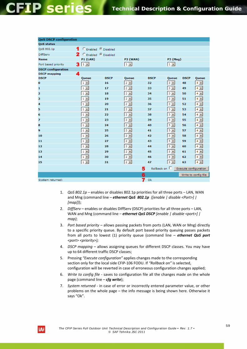
The CFIP Series Full Outdoor Unit Technical Description and Configuration Guide • Rev. 1.7 •
© SAF Tehnika JSC 2011
59
1. QoS 802.1p – enables or disables 802.1p priorities for all three ports – LAN, WAN and Mng (command line – ethernet QoS 802.1p [enable | disable <Port>] | [map]);
2. DiffServ – enables or disables DiffServ (DSCP) priorities for all three ports – LAN, WAN and Mng (command line – ethernet QoS DSCP [enable | disable <port>] | map);
3. Port based priority – allows passing packets from ports (LAN, WAN or Mng) directly to a specific priority queue. By default port based priority queuing passes packets from all ports to lowest (1) priority queue (command line – ethernet QoS port <port> <priority>);
4. DSCP mapping – allows assigning queues for different DSCP classes. You may have up to 64 different traffic DSCP classes;
5. Pressing “Execute configuration” applies changes made to the corresponding section only for the local side CFIP‐106 FODU. If “Rollback on” is selected, configuration will be reverted in case of erroneous configuration changes applied;
6. Write to config file ‐ saves to configuration file all the changes made on the whole page (command line – cfg write);
7. System returned ‐ in case of error or incorrectly entered parameter value, or other problems on the whole page – the info message is being shown here. Otherwise it says “Ok”.
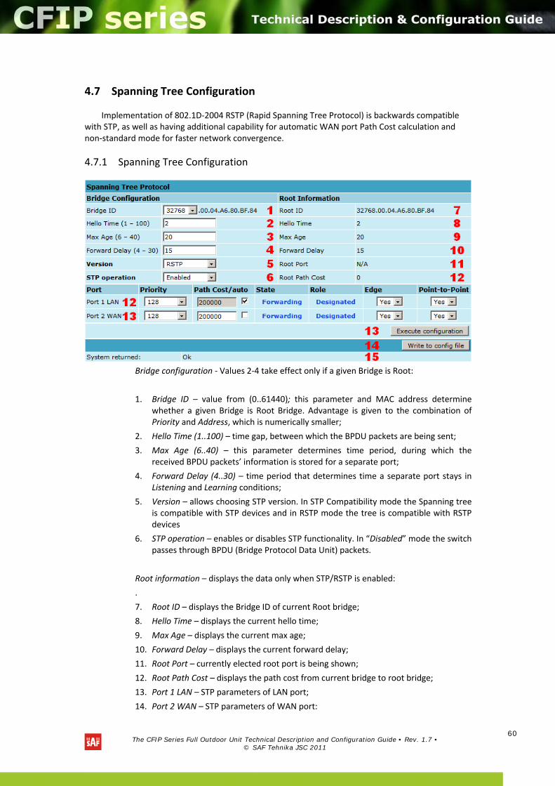
The CFIP Series Full Outdoor Unit Technical Description and Configuration Guide • Rev. 1.7 •
© SAF Tehnika JSC 2011
60
4.7 Spanning Tree Configuration
Implementation of 802.1D‐2004 RSTP (Rapid Spanning Tree Protocol) is backwards compatible with STP, as well as having additional capability for automatic WAN port Path Cost calculation and non‐standard mode for faster network convergence.
4.7.1 Spanning Tree Configuration
Bridge configuration ‐ Values 2‐4 take effect only if a given Bridge is Root:
1. Bridge ID – value from (0..61440); this parameter and MAC address determine whether a given Bridge is Root Bridge. Advantage is given to the combination of Priority and Address, which is numerically smaller;
2. Hello Time (1..100) – time gap, between which the BPDU packets are being sent;
3. Max Age (6..40) – this parameter determines time period, during which the received BPDU packets’ information is stored for a separate port;
4. Forward Delay (4..30) – time period that determines time a separate port stays in Listening and Learning conditions;
5. Version – allows choosing STP version. In STP Compatibility mode the Spanning tree is compatible with STP devices and in RSTP mode the tree is compatible with RSTP devices
6. STP operation – enables or disables STP functionality. In “Disabled” mode the switch passes through BPDU (Bridge Protocol Data Unit) packets.
Root information – displays the data only when STP/RSTP is enabled:
.
7. Root ID – displays the Bridge ID of current Root bridge;
8. Hello Time – displays the current hello time;
9. Max Age – displays the current max age;
10. Forward Delay – displays the current forward delay;
11. Root Port – currently elected root port is being shown;
12. Root Path Cost – displays the path cost from current bridge to root bridge;
13. Port 1 LAN – STP parameters of LAN port;
14. Port 2 WAN – STP parameters of WAN port:
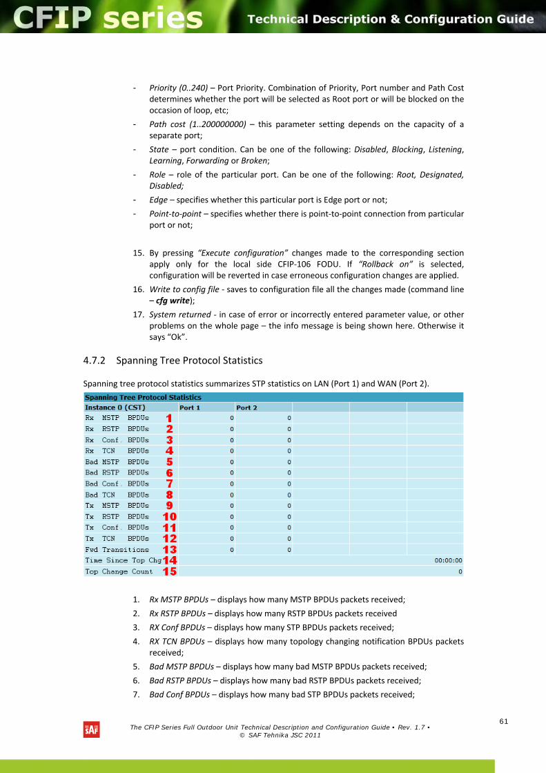
The CFIP Series Full Outdoor Unit Technical Description and Configuration Guide • Rev. 1.7 •
© SAF Tehnika JSC 2011
61
- Priority (0..240) – Port Priority. Combination of Priority, Port number and Path Cost determines whether the port will be selected as Root port or will be blocked on the occasion of loop, etc;
- Path cost (1..200000000) – this parameter setting depends on the capacity of a separate port;
- State – port condition. Can be one of the following: Disabled, Blocking, Listening, Learning, Forwarding or Broken;
- Role – role of the particular port. Can be one of the following: Root, Designated, Disabled;
- Edge – specifies whether this particular port is Edge port or not;
- Point‐to‐point – specifies whether there is point‐to‐point connection from particular port or not;
15. By pressing “Execute configuration” changes made to the corresponding section apply only for the local side CFIP‐106 FODU. If “Rollback on” is selected, configuration will be reverted in case erroneous configuration changes are applied.
16. Write to config file ‐ saves to configuration file all the changes made (command line – cfg write);
17. System returned ‐ in case of error or incorrectly entered parameter value, or other problems on the whole page – the info message is being shown here. Otherwise it says “Ok”.
4.7.2 Spanning Tree Protocol Statistics
Spanning tree protocol statistics summarizes STP statistics on LAN (Port 1) and WAN (Port 2).
1. Rx MSTP BPDUs – displays how many MSTP BPDUs packets received;
2. Rx RSTP BPDUs – displays how many RSTP BPDUs packets received
3. RX Conf BPDUs – displays how many STP BPDUs packets received;
4. RX TCN BPDUs – displays how many topology changing notification BPDUs packets received;
5. Bad MSTP BPDUs – displays how many bad MSTP BPDUs packets received;
6. Bad RSTP BPDUs – displays how many bad RSTP BPDUs packets received;
7. Bad Conf BPDUs – displays how many bad STP BPDUs packets received;
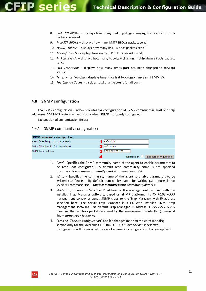
The CFIP Series Full Outdoor Unit Technical Description and Configuration Guide • Rev. 1.7 •
© SAF Tehnika JSC 2011
62
8. Bad TCN BPDUs – displays how many bad topology changing notifications BPDUs packets received;
9. Tx MSTP BPDUs – displays how many MSTP BPDUs packets send;
10. Tx RSTP BPDUs – displays how many RSTP BPDUs packets send;
11. Tx Conf BPDUs ‐ displays how many STP BPDUs packets send;
12. Tx TCN BPDUs – displays how many topology changing notification BPDUs packets send;
13. Fwd Transitions – displays how many times port has been changed to forward status;
14. Times Since Top Chg – displays time since last topology change in HH:MM:SS;
15. Top Change Count ‐ displays total change count for all port;
4.8 SNMP configuration
The SNMP configuration window provides the configuration of SNMP communities, host and trap addresses. SAF NMS system will work only when SNMP is properly configured.
Explanation of customization fields:
4.8.1 SNMP community configuration
1. Read ‐ Specifies the SNMP community name of the agent to enable parameters to
be read (not configured). By default read community name is not specified (command line – snmp community read <communityname>);
2. Write – Specifies the community name of the agent to enable parameters to be written (configured). By default community name for writing parameters is not specified (command line – snmp community write <communityname>);
3. SNMP trap address – Sets the IP address of the management terminal with the installed Trap Manager software, based on SNMP platform. The CFIP‐106 FODU management controller sends SNMP traps to the Trap Manager with IP address specified here. The SNMP Trap Manager is a PC with installed SNMP trap management software. The default Trap Manager IP address is 255.255.255.255 meaning that no trap packets are sent by the management controller (command line – snmp trap <ipaddr>);
4. Pressing “Execute configuration” applies changes made to the corresponding section only for the local side CFIP‐106 FODU. If “Rollback on” is selected, configuration will be reverted in case of erroneous configuration changes applied.
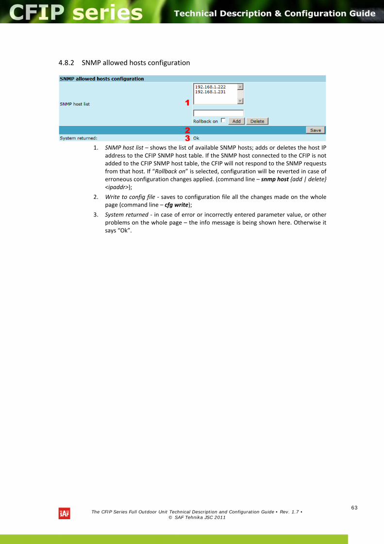
The CFIP Series Full Outdoor Unit Technical Description and Configuration Guide • Rev. 1.7 •
© SAF Tehnika JSC 2011
63
4.8.2 SNMP allowed hosts configuration
1. SNMP host list – shows the list of available SNMP hosts; adds or deletes the host IP
address to the CFIP SNMP host table. If the SNMP host connected to the CFIP is not added to the CFIP SNMP host table, the CFIP will not respond to the SNMP requests from that host. If “Rollback on” is selected, configuration will be reverted in case of erroneous configuration changes applied. (command line – snmp host add | delete <ipaddr>);
2. Write to config file ‐ saves to configuration file all the changes made on the whole page (command line – cfg write);
3. System returned ‐ in case of error or incorrectly entered parameter value, or other problems on the whole page – the info message is being shown here. Otherwise it says “Ok”.
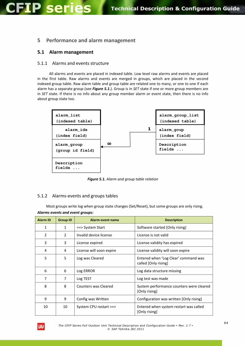
The CFIP Series Full Outdoor Unit Technical Description and Configuration Guide • Rev. 1.7 •
© SAF Tehnika JSC 2011
64
5 Performance and alarm management
5.1 Alarm management
5.1.1 Alarms and events structure
All alarms and events are placed in indexed table. Low level raw alarms and events are placed in the first table. Raw alarms and events are merged in groups, which are placed in the second indexed group table. Raw alarm table and group table are related one to many, or one to one if each alarm has a separate group (see Figure 5.1.). Group is in SET state if one or more group members are in SET state. If there is no info about any group member alarm or event state, then there is no info about group state too.
Figure 5.1. Alarm and group table relation
5.1.2 Alarms‐events and groups tables
Most groups write log when group state changes (Set/Reset), but some groups are only rising.
Alarms events and event groups:
Alarm ID Group ID Alarm‐event name Description
1 1 ==> System Start Software started [Only rising]
2 2 Invalid device license License is not valid
3 3 License expired License validity has expired
4 4 License will soon expire License validity will soon expire
5 5 Log was Cleared Entered when ‘Log Clear’ command was called [Only rising]
6 6 Log ERROR Log data structure missing
7 7 Log TEST Log test was made
8 8 Counters was Cleared System performance counters were cleared [Only rising]
9 9 Config was Written Configuration was written [Only rising]
10 10 System CPU restart ==> Entered when system restart was called [Only rising]
1
alarm_list
(indexed table)
alarm_idx
(index field)
alarm_group
(group id field)
alarm_group_list
(indexed table)
alarm_goup
(index field)
∞
Description fields ...
Description fields ...
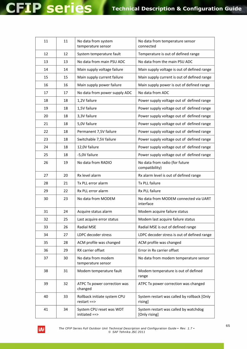
The CFIP Series Full Outdoor Unit Technical Description and Configuration Guide • Rev. 1.7 •
© SAF Tehnika JSC 2011
65
11 11 No data from system temperature sensor
No data from temperature sensor connected
12 12 System temperature fault Temperature is out of defined range
13 13 No data from main PSU ADC No data from the main PSU ADC
14 14 Main supply voltage failure Main supply voltage is out of defined range
15 15 Main supply current failure Main supply current is out of defined range
16 16 Main supply power failure Main supply power is out of defined range
17 17 No data from power supply ADC No data from ADC
18 18 1,2V failure Power supply voltage out of defined range
19 18 1,5V failure Power supply voltage out of defined range
20 18 3,3V failure Power supply voltage out of defined range
21 18 5,0V failure Power supply voltage out of defined range
22 18 Permanent 7,5V failure Power supply voltage out of defined range
23 18 Switchable 7,5V failure Power supply voltage out of defined range
24 18 12,0V failure Power supply voltage out of defined range
25 18 ‐5,0V failure Power supply voltage out of defined range
26 19 No data from RADIO No data from radio (for future compatibility)
27 20 Rx level alarm Rx alarm level is out of defined range
28 21 Tx PLL error alarm Tx PLL failure
29 22 Rx PLL error alarm Rx PLL failure
30 23 No data from MODEM No data from MODEM connected via UART interface
31 24 Acquire status alarm Modem acquire failure status
32 25 Last acquire error status Modem last acquire failure status
33 26 Radial MSE Radial MSE is out of defined range
34 27 LDPC decoder stress LDPC decoder stress is out of defined range
35 28 ACM profile was changed ACM profile was changed
36 29 RX carrier offset Error in Rx carrier offset
37 30 No data from modem temperature sensor
No data from modem temperature sensor
38 31 Modem temperature fault Modem temperature is out of defined range
39 32 ATPC Tx power correction was changed
ATPC Tx power correction was changed
40 33 Rollback initiate system CPU restart ==>
System restart was called by rollback [Only rising]
41 34 System CPU reset was WDT initiated ==>
System restart was called by watchdog [Only rising]
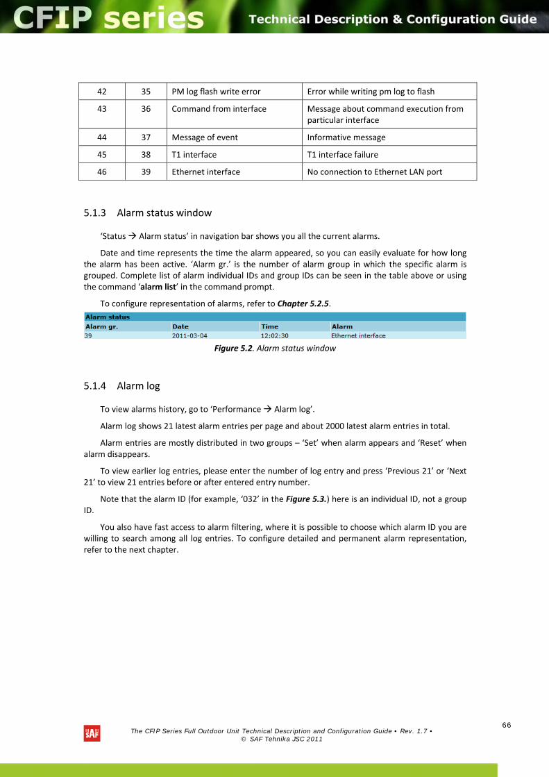
The CFIP Series Full Outdoor Unit Technical Description and Configuration Guide • Rev. 1.7 •
© SAF Tehnika JSC 2011
66
42 35 PM log flash write error Error while writing pm log to flash
43 36 Command from interface Message about command execution from particular interface
44 37 Message of event Informative message
45 38 T1 interface T1 interface failure
46 39 Ethernet interface No connection to Ethernet LAN port
5.1.3 Alarm status window
‘Status Alarm status’ in navigation bar shows you all the current alarms.
Date and time represents the time the alarm appeared, so you can easily evaluate for how long the alarm has been active. ‘Alarm gr.’ is the number of alarm group in which the specific alarm is grouped. Complete list of alarm individual IDs and group IDs can be seen in the table above or using the command ‘alarm list’ in the command prompt.
To configure representation of alarms, refer to Chapter 5.2.5.
Figure 5.2. Alarm status window
5.1.4 Alarm log
To view alarms history, go to ‘Performance Alarm log’.
Alarm log shows 21 latest alarm entries per page and about 2000 latest alarm entries in total.
Alarm entries are mostly distributed in two groups – ‘Set’ when alarm appears and ‘Reset’ when alarm disappears.
To view earlier log entries, please enter the number of log entry and press ‘Previous 21’ or ‘Next 21’ to view 21 entries before or after entered entry number.
Note that the alarm ID (for example, ‘032’ in the Figure 5.3.) here is an individual ID, not a group ID.
You also have fast access to alarm filtering, where it is possible to choose which alarm ID you are willing to search among all log entries. To configure detailed and permanent alarm representation, refer to the next chapter.
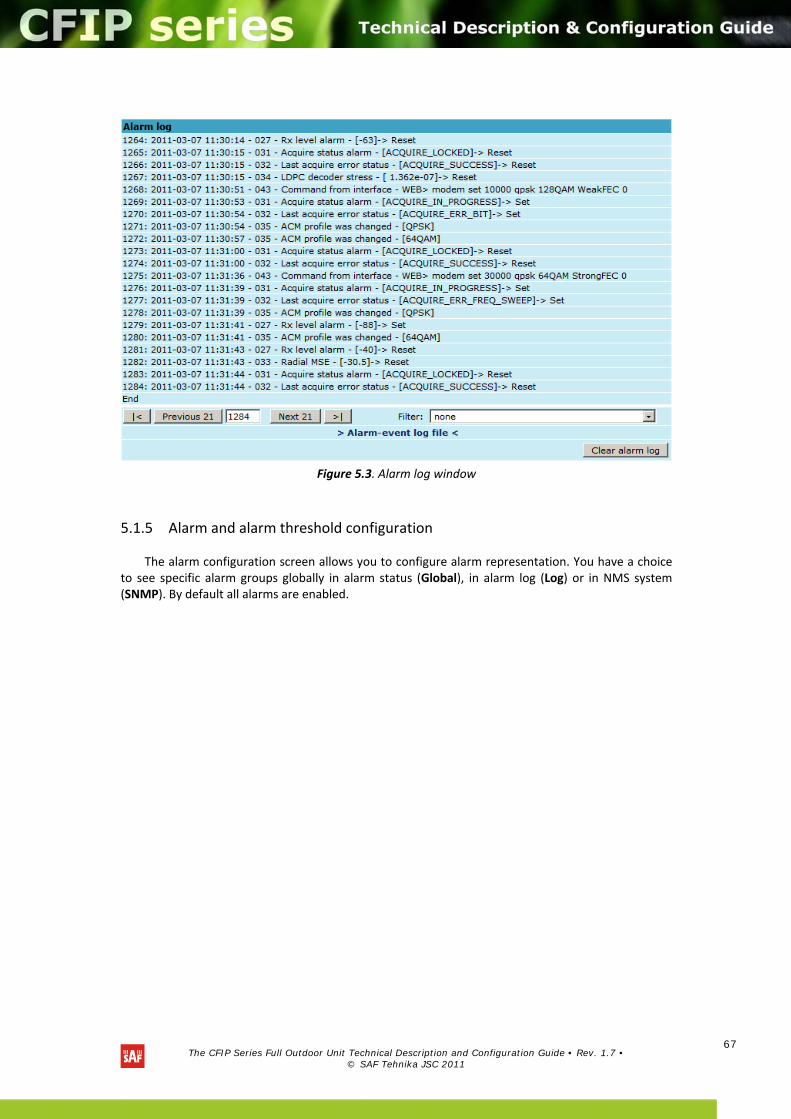
The CFIP Series Full Outdoor Unit Technical Description and Configuration Guide • Rev. 1.7 •
© SAF Tehnika JSC 2011
67
Figure 5.3. Alarm log window
5.1.5 Alarm and alarm threshold configuration
The alarm configuration screen allows you to configure alarm representation. You have a choice to see specific alarm groups globally in alarm status (Global), in alarm log (Log) or in NMS system (SNMP). By default all alarms are enabled.
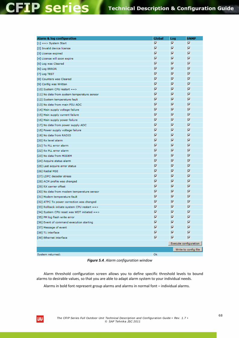
The CFIP Series Full Outdoor Unit Technical Description and Configuration Guide • Rev. 1.7 •
© SAF Tehnika JSC 2011
68
Figure 5.4. Alarm configuration window
Alarm threshold configuration screen allows you to define specific threshold levels to bound alarms to desirable values, so that you are able to adapt alarm system to your individual needs.
Alarms in bold font represent group alarms and alarms in normal font – individual alarms.
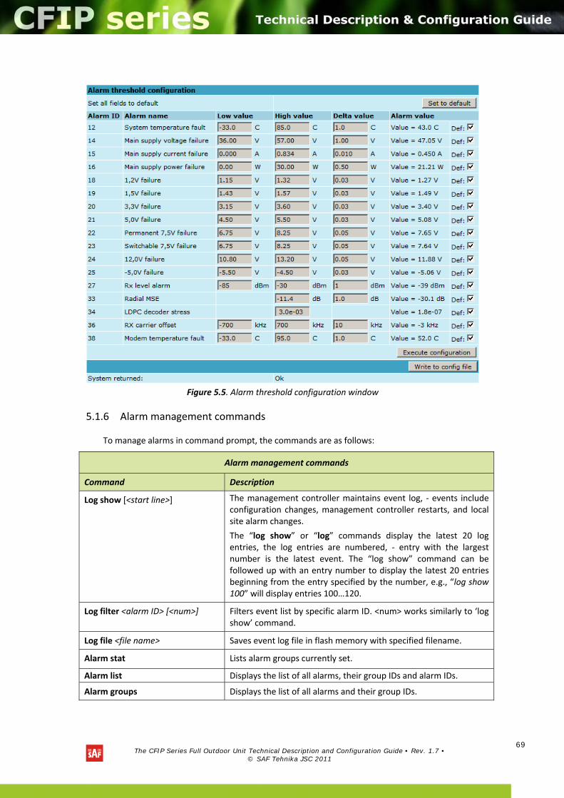
The CFIP Series Full Outdoor Unit Technical Description and Configuration Guide • Rev. 1.7 •
© SAF Tehnika JSC 2011
69
Figure 5.5. Alarm threshold configuration window
5.1.6 Alarm management commands
To manage alarms in command prompt, the commands are as follows:
Alarm management commands
Command Description
Log show [<start line>] The management controller maintains event log, ‐ events include configuration changes, management controller restarts, and local site alarm changes.
The “log show” or “log” commands display the latest 20 log entries, the log entries are numbered, ‐ entry with the largest number is the latest event. The “log show” command can be followed up with an entry number to display the latest 20 entries beginning from the entry specified by the number, e.g., “log show 100” will display entries 100…120.
Log filter <alarm ID> [<num>] Filters event list by specific alarm ID. <num> works similarly to ‘log show’ command.
Log file <file name> Saves event log file in flash memory with specified filename.
Alarm stat Lists alarm groups currently set.
Alarm list Displays the list of all alarms, their group IDs and alarm IDs.
Alarm groups Displays the list of all alarms and their group IDs.
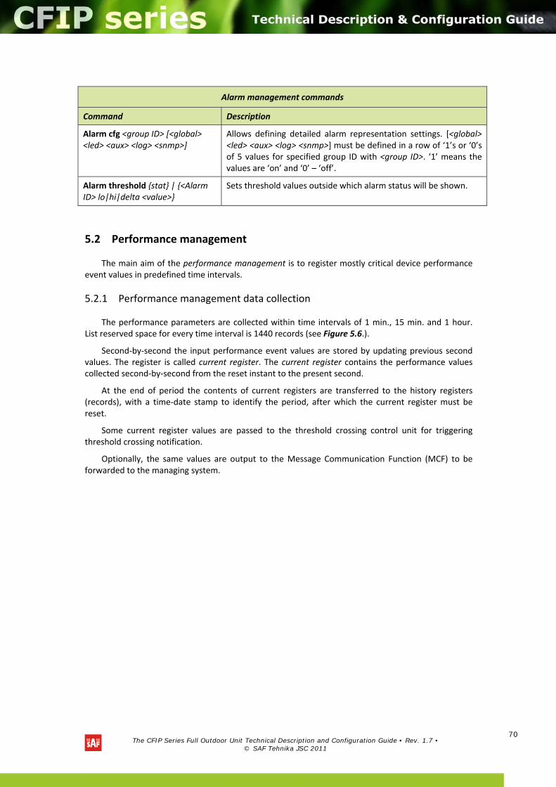
The CFIP Series Full Outdoor Unit Technical Description and Configuration Guide • Rev. 1.7 •
© SAF Tehnika JSC 2011
70
5.2 Performance management
The main aim of the performance management is to register mostly critical device performance event values in predefined time intervals.
5.2.1 Performance management data collection
The performance parameters are collected within time intervals of 1 min., 15 min. and 1 hour. List reserved space for every time interval is 1440 records (see Figure 5.6.).
Second‐by‐second the input performance event values are stored by updating previous second values. The register is called current register. The current register contains the performance values collected second‐by‐second from the reset instant to the present second.
At the end of period the contents of current registers are transferred to the history registers (records), with a time‐date stamp to identify the period, after which the current register must be reset.
Some current register values are passed to the threshold crossing control unit for triggering threshold crossing notification.
Optionally, the same values are output to the Message Communication Function (MCF) to be forwarded to the managing system.
Alarm management commands
Command Description
Alarm cfg <group ID> [<global> <led> <aux> <log> <snmp>]
Allows defining detailed alarm representation settings. [<global> <led> <aux> <log> <snmp>] must be defined in a row of ‘1’s or ‘0’s of 5 values for specified group ID with <group ID>. ‘1’ means the values are ‘on’ and ‘0’ – ‘off’.
Alarm threshold stat | <Alarm ID> lo|hi|delta <value>
Sets threshold values outside which alarm status will be shown.
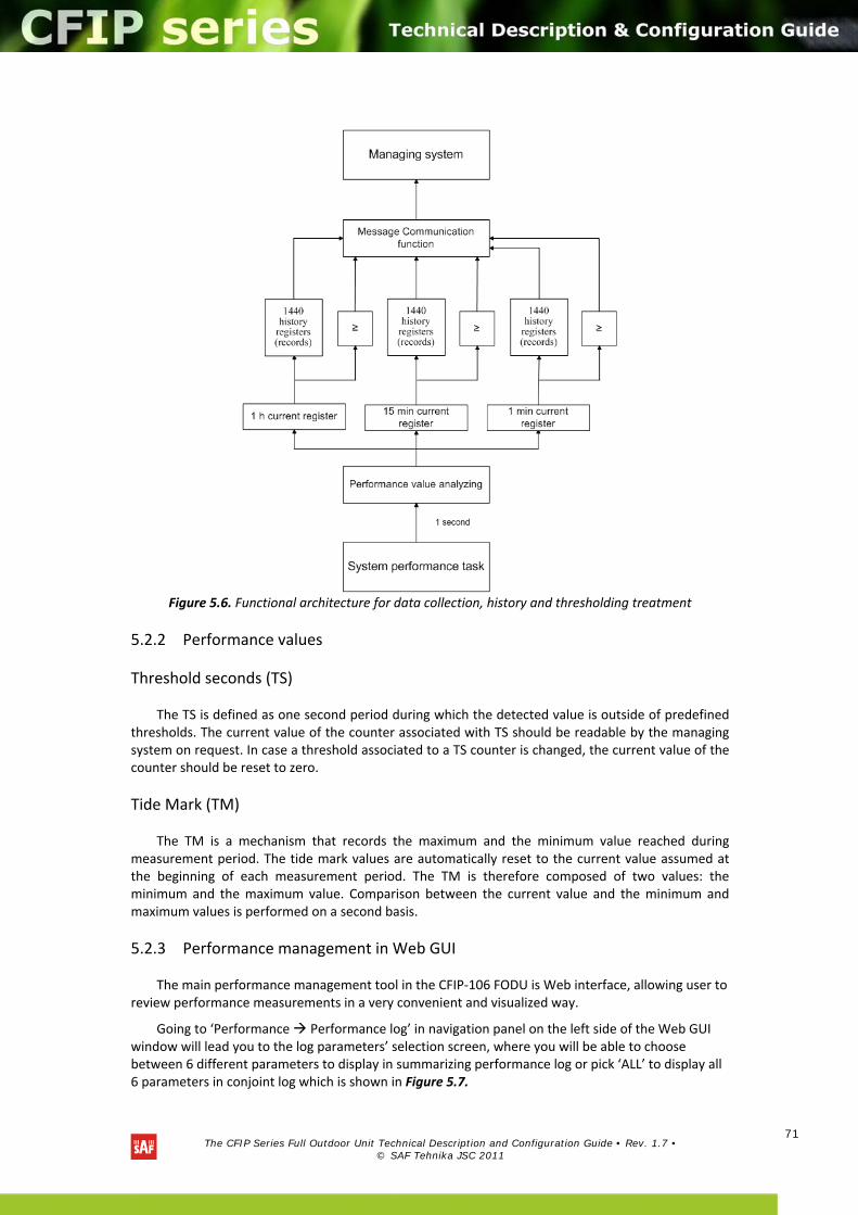
The CFIP Series Full Outdoor Unit Technical Description and Configuration Guide • Rev. 1.7 •
© SAF Tehnika JSC 2011
71
Figure 5.6. Functional architecture for data collection, history and thresholding treatment
5.2.2 Performance values
Threshold seconds (TS)
The TS is defined as one second period during which the detected value is outside of predefined thresholds. The current value of the counter associated with TS should be readable by the managing system on request. In case a threshold associated to a TS counter is changed, the current value of the counter should be reset to zero.
Tide Mark (TM)
The TM is a mechanism that records the maximum and the minimum value reached during measurement period. The tide mark values are automatically reset to the current value assumed at the beginning of each measurement period. The TM is therefore composed of two values: the minimum and the maximum value. Comparison between the current value and the minimum and maximum values is performed on a second basis.
5.2.3 Performance management in Web GUI
The main performance management tool in the CFIP‐106 FODU is Web interface, allowing user to review performance measurements in a very convenient and visualized way.
Going to ‘Performance Performance log’ in navigation panel on the left side of the Web GUI window will lead you to the log parameters’ selection screen, where you will be able to choose between 6 different parameters to display in summarizing performance log or pick ‘ALL’ to display all 6 parameters in conjoint log which is shown in Figure 5.7.
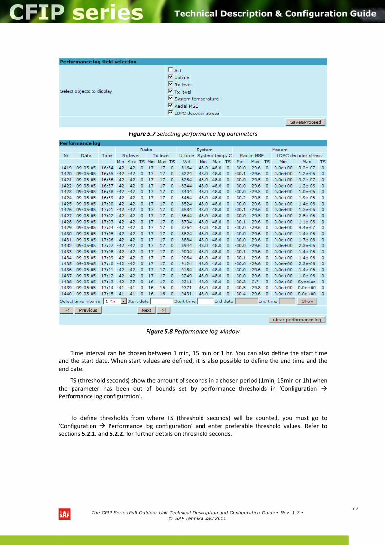
The CFIP Series Full Outdoor Unit Technical Description and Configuration Guide • Rev. 1.7 •
© SAF Tehnika JSC 2011
72
Figure 5.7 Selecting performance log parameters
Figure 5.8 Performance log window
Time interval can be chosen between 1 min, 15 min or 1 hr. You can also define the start time and the start date. When start values are defined, it is also possible to define the end time and the end date.
TS (threshold seconds) show the amount of seconds in a chosen period (1min, 15min or 1h) when the parameter has been out of bounds set by performance thresholds in ‘Configuration Performance log configuration’.
To define thresholds from where TS (threshold seconds) will be counted, you must go to ‘Configuration Performance log configuration’ and enter preferable threshold values. Refer to sections 5.2.1. and 5.2.2. for further details on threshold seconds.
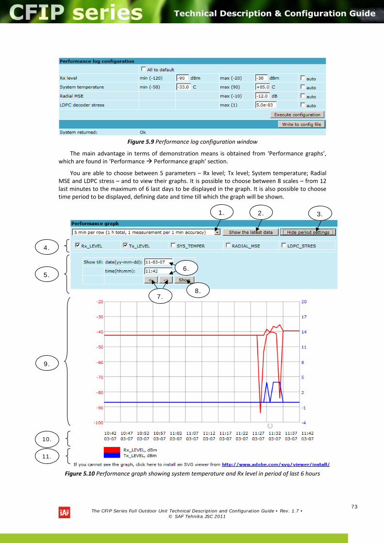
The CFIP Series Full Outdoor Unit Technical Description and Configuration Guide • Rev. 1.7 •
© SAF Tehnika JSC 2011
73
Figure 5.9 Performance log configuration window
The main advantage in terms of demonstration means is obtained from ‘Performance graphs’, which are found in ‘Performance Performance graph’ section.
You are able to choose between 5 parameters – Rx level; Tx level; System temperature; Radial MSE and LDPC stress – and to view their graphs. It is possible to choose between 8 scales – from 12 last minutes to the maximum of 6 last days to be displayed in the graph. It is also possible to choose time period to be displayed, defining date and time till which the graph will be shown.
Figure 5.10 Performance graph showing system temperature and Rx level in period of last 6 hours
1.
10.
9.
5.
7. 8.
6.
4.
2. 3.
11.

The CFIP Series Full Outdoor Unit Technical Description and Configuration Guide • Rev. 1.7 •
© SAF Tehnika JSC 2011
74
1. Time scale selector. User can select the scale and accuracy (1 / 15 / 60 minutes). The lower accuracy, the longer period will be available for data (mechanism of the performance management system)
2. Updates the performance graph; the latest data is shown
3. Shows / hides period settings (point 5)
4. Performance data selector. .Only two performance parameters can be selected at a time
5. Period settings. Allows the user to specify time period for the graph
6. Date and time fields. The date format is “yy‐mm‐dd”, the time format is “hh:mm”
7. Sets date and time fields (point 6) one screen back / forth
8. Shows / updates the performance graph using the period settings (point 5)
9. Performance graph. Displays two performance parameters. Each parameter is shown with the minimum and maximum curves, which are in the same color. The curves in red have the scale on the left, while the curves in blue have the scale on the right
10. Time scale. Shows the time scale chosen from the time scale selector (point 1) for the performance data available. If no data is available for the according moment, “__:__” is shown
11. Legend for the curves of the performance graph. Contains the color, the name and the unit of measurement, if available.
In case no performance data has been recorded, or the period specified has no data, “No data” is shown (instead of points 9, 10, 11).
5.2.4 Constellation diagram
A constellation diagram is a representation of a signal modulated by the digital modulation schemes 32APSK, 16APSK or QPSK. It displays the signal as a two‐dimensional scatter diagram in the complex plane at symbol sampling instants. Measured constellation diagram can be used to recognize the type of interference and distortion in a signal.
For the purpose of analyzing the received signal quality, some types of corruption are evident in the constellation diagram. For example:
1) Gaussian noise is displayed as fuzzy constellation points:
Figure 5.11. Gaussian noise (QPSK)

The CFIP Series Full Outdoor Unit Technical Description and Configuration Guide • Rev. 1.7 •
© SAF Tehnika JSC 2011
75
2) Non‐coherent single frequency interference is displayed as circular constellation points:
Figure 5.12. Non‐coherent single frequency interference (QPSK)
3) Phase noise is displayed as rotationally spreading constellation points:
Figure 5.13. Phase noise (QPSK)
4) Amplitude compression causes the corner points to move towards the centre:
Figure 5.14. Amplitude compression (64QAM)
Examples of CFIP constellation diagrams under excellent conditions are shown below:
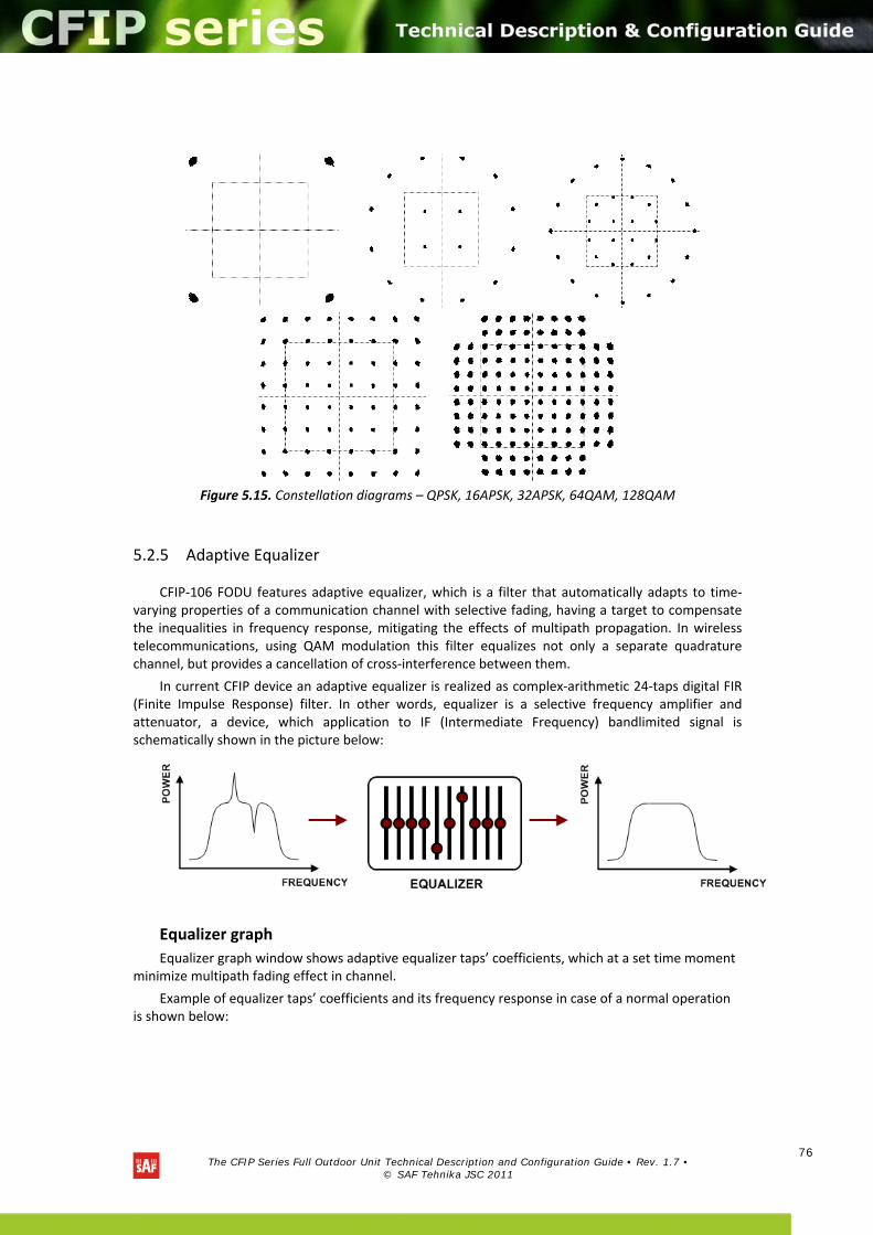
The CFIP Series Full Outdoor Unit Technical Description and Configuration Guide • Rev. 1.7 •
© SAF Tehnika JSC 2011
76
Figure 5.15. Constellation diagrams – QPSK, 16APSK, 32APSK, 64QAM, 128QAM
5.2.5 Adaptive Equalizer
CFIP‐106 FODU features adaptive equalizer, which is a filter that automatically adapts to time‐varying properties of a communication channel with selective fading, having a target to compensate the inequalities in frequency response, mitigating the effects of multipath propagation. In wireless telecommunications, using QAM modulation this filter equalizes not only a separate quadrature channel, but provides a cancellation of cross‐interference between them.
In current CFIP device an adaptive equalizer is realized as complex‐arithmetic 24‐taps digital FIR (Finite Impulse Response) filter. In other words, equalizer is a selective frequency amplifier and attenuator, a device, which application to IF (Intermediate Frequency) bandlimited signal is schematically shown in the picture below:
Equalizer graph
Equalizer graph window shows adaptive equalizer taps’ coefficients, which at a set time moment minimize multipath fading effect in channel.
Example of equalizer taps’ coefficients and its frequency response in case of a normal operation is shown below:
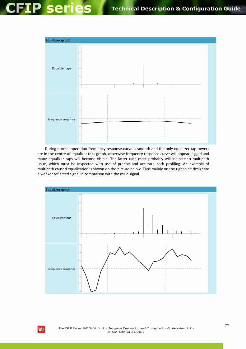
The CFIP Series Full Outdoor Unit Technical Description and Configuration Guide • Rev. 1.7 •
© SAF Tehnika JSC 2011
77
During normal operation frequency response curve is smooth and the only equalizer tap towers
are in the centre of equalizer taps graph, otherwise frequency response curve will appear jagged and many equalizer taps will become visible. The latter case most probably will indicate to multipath issue, which must be inspected with use of precise and accurate path profiling. An example of multipath caused equalization is shown on the picture below. Taps mainly on the right side designate a weaker reflected signal in comparison with the main signal.
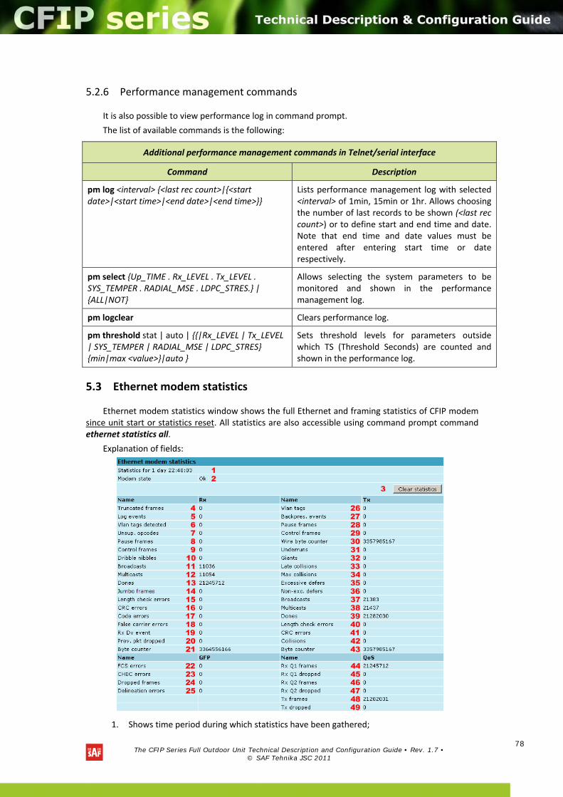
The CFIP Series Full Outdoor Unit Technical Description and Configuration Guide • Rev. 1.7 •
© SAF Tehnika JSC 2011
78
5.2.6 Performance management commands
It is also possible to view performance log in command prompt.
The list of available commands is the following:
5.3 Ethernet modem statistics
Ethernet modem statistics window shows the full Ethernet and framing statistics of CFIP modem since unit start or statistics reset. All statistics are also accessible using command prompt command ethernet statistics all.
Explanation of fields:
1. Shows time period during which statistics have been gathered;
Additional performance management commands in Telnet/serial interface
Command Description
pm log <interval> <last rec count>|<start date>|<start time>|<end date>|<end time>
Lists performance management log with selected <interval> of 1min, 15min or 1hr. Allows choosing the number of last records to be shown (<last rec count>) or to define start and end time and date. Note that end time and date values must be entered after entering start time or date respectively.
pm select Up_TIME . Rx_LEVEL . Tx_LEVEL . SYS_TEMPER . RADIAL_MSE . LDPC_STRES. | ALL|NOT
Allows selecting the system parameters to be monitored and shown in the performance management log.
pm logclear Clears performance log.
pm threshold stat | auto | |Rx_LEVEL | Tx_LEVEL | SYS_TEMPER | RADIAL_MSE | LDPC_STRES min|max <value>|auto
Sets threshold levels for parameters outside which TS (Threshold Seconds) are counted and shown in the performance log.

The CFIP Series Full Outdoor Unit Technical Description and Configuration Guide • Rev. 1.7 •
© SAF Tehnika JSC 2011
79
2. Modem state – shows if the modem is operating correctly;
3. Clear statistics – resets all statistics counters (not available for “guest” account);
4. Truncated frames – number of truncated received frames;
5. Long events – frames having byte count greater than MAXIMUM FRAME SIZE parameter (1518, 1536 or 1916 bytes);
6. Vlan tags detected – VLAN tagged frames;
7. Unsup. opcodes – frames recognized as control frames but contained an Unknown Opcode;
8. Pause frames – frames received are control frames with valid PAUSE opcodes;
9. Control frames – frames received as control frames;
10. Dribble nibbles – indicates that following the end of the packet additional 1 to 7 bits are received. A single nibble, named the dribble nibble, is formed but not sent to the system;
11. Broadcasts – packets, which destination address contained broadcast address;
12. Multicasts – packets, which destination address contained multicast address;
13. Dones – reception of packets successfully completed;
14. Jumbo frames – frame Type/Length field larger than 1518 (Type Field) bytes;
15. Length check errors – frame length field in the packet does not match the actual data byte length and is not a Type Field;
16. CRC errors – frame CRC do not match the internally generated CRC;
17. Code errors – one or more nibbles are signalled as errors during reception of the packet;
18. False carrier errors – indicates that following the last received statistics vector, a false carrier was detected, noted and reported with next received statistics. The false carrier is not associated with this packet. False carrier is activated on the receiving channel that does not result in a packet receive attempt being made;
19. Rx Dv event – indicates that the last receiving event seen is too short to be a valid packet;
20. Prev. pkt dropped – indicates that since the last RSV, a packet is dropped (i.e. interframe gap too small);
21. Byte counter – total number of bytes received on the wire, not counting collided bytes;
22. FCS errors – number of generic framing procedure (GFP) frames with CRC errors received by the de‐encapsulation block;
23. CHEC errors – number of generic framing procedure (GFP) frames with CHEC errors received by the de‐encapsulation block;
24. Dropped frames – number of generic framing procedure (GFP) frames that were dropped in the de‐encapsulation block;
25. Delineation errors – number of ‘lost of synchronization’ events;
26. Vlan tags – number of VLAN tagged packets, 32‐bit counter;
27. Backpres. events – carrier‐sense‐method backpressure was previously applied;
28. Pause frames – frames transmitted are control frames with a valid PAUSE opcodes;
29. Control frames – frames transmitted are control frames;
30. Wire byte counter – total number of bytes transmitted on the wire, including all bytes from collided attempts;
31. Underruns – underruns occur during frame transmission;
32. Giants – frames having byte count greater than the MAXIMUM FRAME SIZE parameter (1516, 1536 or 1916 bytes);
33. Late collisions – Collisions occurred beyond the collision window (512 bit times);
34. Max collisions – packets aborted after number of collisions exceeded the RETRANSMISSION MAXIMUM parameter;
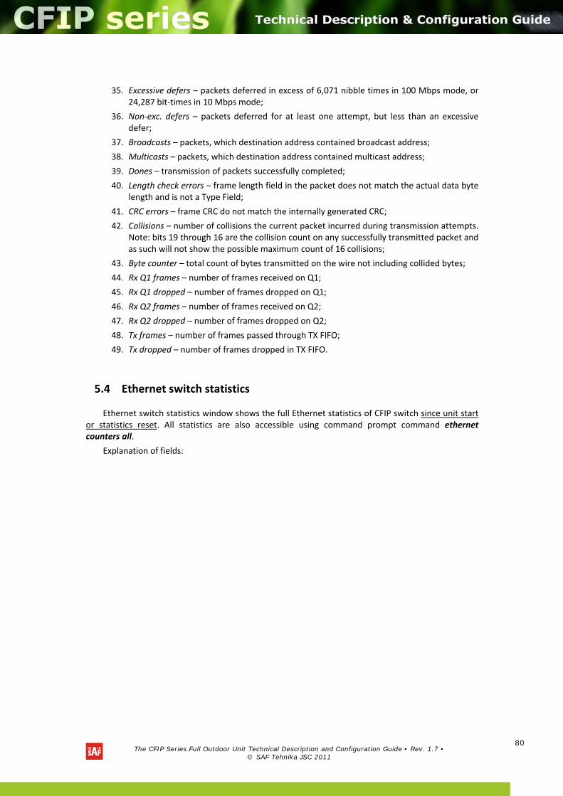
The CFIP Series Full Outdoor Unit Technical Description and Configuration Guide • Rev. 1.7 •
© SAF Tehnika JSC 2011
80
35. Excessive defers – packets deferred in excess of 6,071 nibble times in 100 Mbps mode, or 24,287 bit‐times in 10 Mbps mode;
36. Non‐exc. defers – packets deferred for at least one attempt, but less than an excessive defer;
37. Broadcasts – packets, which destination address contained broadcast address;
38. Multicasts – packets, which destination address contained multicast address;
39. Dones – transmission of packets successfully completed;
40. Length check errors – frame length field in the packet does not match the actual data byte length and is not a Type Field;
41. CRC errors – frame CRC do not match the internally generated CRC;
42. Collisions – number of collisions the current packet incurred during transmission attempts. Note: bits 19 through 16 are the collision count on any successfully transmitted packet and as such will not show the possible maximum count of 16 collisions;
43. Byte counter – total count of bytes transmitted on the wire not including collided bytes;
44. Rx Q1 frames – number of frames received on Q1;
45. Rx Q1 dropped – number of frames dropped on Q1;
46. Rx Q2 frames – number of frames received on Q2;
47. Rx Q2 dropped – number of frames dropped on Q2;
48. Tx frames – number of frames passed through TX FIFO;
49. Tx dropped – number of frames dropped in TX FIFO.
5.4 Ethernet switch statistics
Ethernet switch statistics window shows the full Ethernet statistics of CFIP switch since unit start or statistics reset. All statistics are also accessible using command prompt command ethernet counters all.
Explanation of fields:
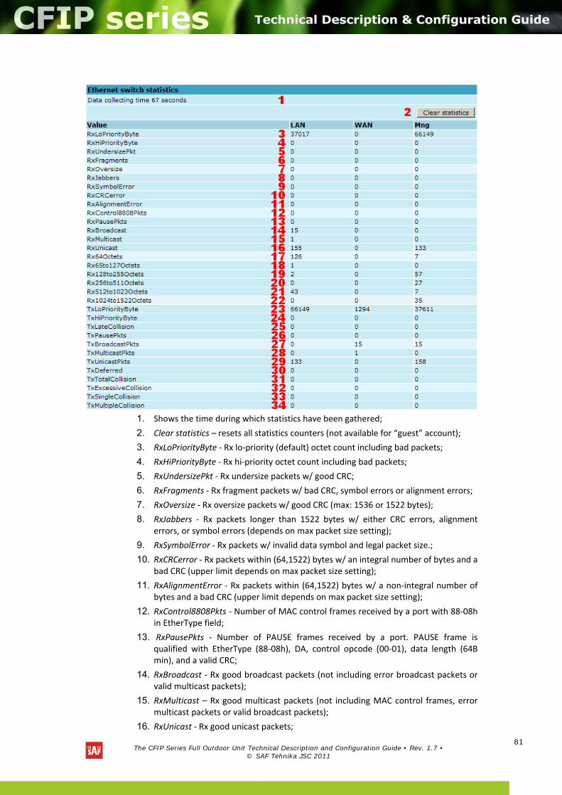
The CFIP Series Full Outdoor Unit Technical Description and Configuration Guide • Rev. 1.7 •
© SAF Tehnika JSC 2011
81
1. Shows the time during which statistics have been gathered;
2. Clear statistics – resets all statistics counters (not available for “guest” account);
3. RxLoPriorityByte ‐ Rx lo‐priority (default) octet count including bad packets;
4. RxHiPriorityByte ‐ Rx hi‐priority octet count including bad packets;
5. RxUndersizePkt ‐ Rx undersize packets w/ good CRC;
6. RxFragments ‐ Rx fragment packets w/ bad CRC, symbol errors or alignment errors;
7. RxOversize ‐ Rx oversize packets w/ good CRC (max: 1536 or 1522 bytes);
8. RxJabbers ‐ Rx packets longer than 1522 bytes w/ either CRC errors, alignment errors, or symbol errors (depends on max packet size setting);
9. RxSymbolError ‐ Rx packets w/ invalid data symbol and legal packet size.;
10. RxCRCerror ‐ Rx packets within (64,1522) bytes w/ an integral number of bytes and a bad CRC (upper limit depends on max packet size setting);
11. RxAlignmentError ‐ Rx packets within (64,1522) bytes w/ a non‐integral number of bytes and a bad CRC (upper limit depends on max packet size setting);
12. RxControl8808Pkts ‐ Number of MAC control frames received by a port with 88‐08h in EtherType field;
13. RxPausePkts ‐ Number of PAUSE frames received by a port. PAUSE frame is qualified with EtherType (88‐08h), DA, control opcode (00‐01), data length (64B min), and a valid CRC;
14. RxBroadcast ‐ Rx good broadcast packets (not including error broadcast packets or valid multicast packets);
15. RxMulticast – Rx good multicast packets (not including MAC control frames, error multicast packets or valid broadcast packets);
16. RxUnicast ‐ Rx good unicast packets;

The CFIP Series Full Outdoor Unit Technical Description and Configuration Guide • Rev. 1.7 •
© SAF Tehnika JSC 2011
82
17. Rx64Octets – Total Rx packets (bad packets included) that were 64 octets in length;
18. Rx65to127Octets – Total Rx packets (bad packets included) that are between 65 and 127 octets in length;
19. Rx128to255Octets ‐ Total Rx packets (bad packets included) that are between 128 and 255 octets in length;
20. Rx256to511Octets ‐ Total Rx packets (bad packets included) that are between 256 and 511 octets in length;
21. Rx512to1023Octets ‐ Total Rx packets (bad packets included) that are between 512 and 1023 octets in length;
22. Rx1024to1522Octets ‐ Total Rx packets (bad packets included) that are between 1024 and 1522 octets in length (upper limit depends on max packet size setting);
23. TxLoPriorityByte ‐ Tx lo‐priority good octet count, including PAUSE packets;
24. TxHiPriorityByte ‐ Tx hi‐priority good octet count, including PAUSE packets;
25. TxLateCollision – The number of times a collision is detected later than 512 bit‐times into the Tx of a packet;
26. TxPausePkts ‐ Number of PAUSE frames transmitted by a port;
27. TxBroadcastPkts ‐ Tx good broadcast packets (not including error broadcast or valid multicast packets);
28. TxMulticastPkts ‐ Tx good multicast packets (not including error multicast packets or valid broadcast packets);
29. TxUnicastPkts – Tx good unicast packets;
30. TxDeferred ‐ Tx packets by a port for which the 1st Tx attempt is delayed due to the busy medium;
31. TxTotalCollision – Tx total collision, half duplex only;
32. TxExcessiveCollision – A count of frames for which Tx fails due to excessive collisions;
33. TxSingleCollision ‐ Successfully Tx frames on a port for which Tx is inhibited by exactly one collision;
34. TxMultipleCollision – Successfully Tx frames on a port for which Tx is inhibited by more than one collision.
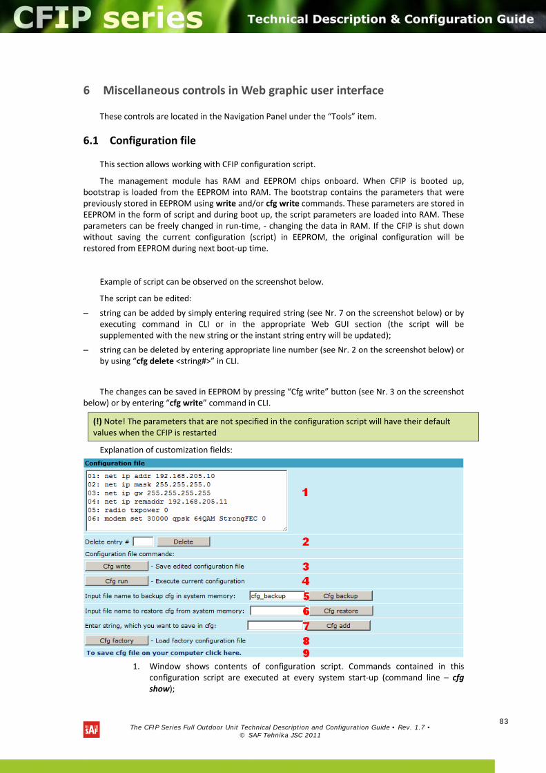
The CFIP Series Full Outdoor Unit Technical Description and Configuration Guide • Rev. 1.7 •
© SAF Tehnika JSC 2011
83
6 Miscellaneous controls in Web graphic user interface
These controls are located in the Navigation Panel under the “Tools” item.
6.1 Configuration file
This section allows working with CFIP configuration script.
The management module has RAM and EEPROM chips onboard. When CFIP is booted up, bootstrap is loaded from the EEPROM into RAM. The bootstrap contains the parameters that were previously stored in EEPROM using write and/or cfg write commands. These parameters are stored in EEPROM in the form of script and during boot up, the script parameters are loaded into RAM. These parameters can be freely changed in run‐time, ‐ changing the data in RAM. If the CFIP is shut down without saving the current configuration (script) in EEPROM, the original configuration will be restored from EEPROM during next boot‐up time.
Example of script can be observed on the screenshot below.
The script can be edited:
– string can be added by simply entering required string (see Nr. 7 on the screenshot below) or by executing command in CLI or in the appropriate Web GUI section (the script will be supplemented with the new string or the instant string entry will be updated);
– string can be deleted by entering appropriate line number (see Nr. 2 on the screenshot below) or by using “cfg delete <string#>” in CLI.
The changes can be saved in EEPROM by pressing “Cfg write” button (see Nr. 3 on the screenshot below) or by entering “cfg write” command in CLI.
Explanation of customization fields:
1. Window shows contents of configuration script. Commands contained in this configuration script are executed at every system start‐up (command line – cfg show);
(!) Note! The parameters that are not specified in the configuration script will have their default values when the CFIP is restarted
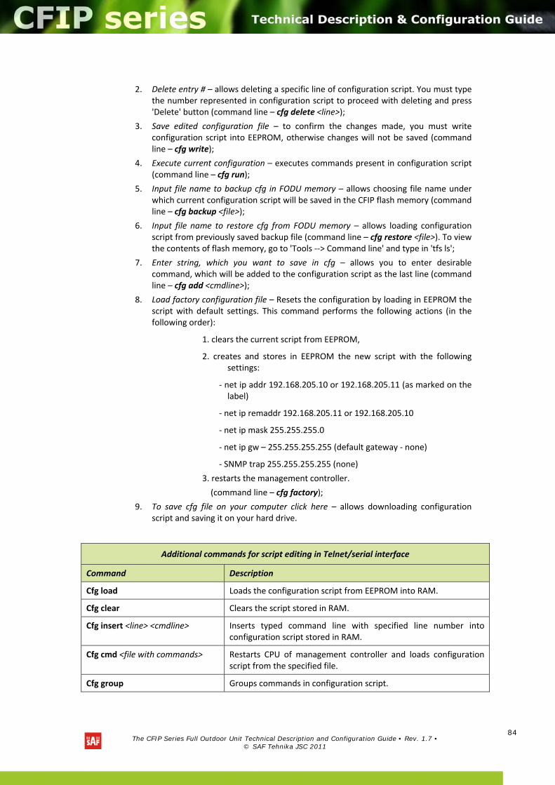
The CFIP Series Full Outdoor Unit Technical Description and Configuration Guide • Rev. 1.7 •
© SAF Tehnika JSC 2011
84
2. Delete entry # – allows deleting a specific line of configuration script. You must type the number represented in configuration script to proceed with deleting and press 'Delete' button (command line – cfg delete <line>);
3. Save edited configuration file – to confirm the changes made, you must write configuration script into EEPROM, otherwise changes will not be saved (command line – cfg write);
4. Execute current configuration – executes commands present in configuration script (command line – cfg run);
5. Input file name to backup cfg in FODU memory – allows choosing file name under which current configuration script will be saved in the CFIP flash memory (command line – cfg backup <file>);
6. Input file name to restore cfg from FODU memory – allows loading configuration script from previously saved backup file (command line – cfg restore <file>). To view the contents of flash memory, go to 'Tools ‐‐> Command line' and type in 'tfs ls';
7. Enter string, which you want to save in cfg – allows you to enter desirable command, which will be added to the configuration script as the last line (command line – cfg add <cmdline>);
8. Load factory configuration file – Resets the configuration by loading in EEPROM the script with default settings. This command performs the following actions (in the following order):
1. clears the current script from EEPROM,
2. creates and stores in EEPROM the new script with the following settings:
‐ net ip addr 192.168.205.10 or 192.168.205.11 (as marked on the label)
‐ net ip remaddr 192.168.205.11 or 192.168.205.10
‐ net ip mask 255.255.255.0
‐ net ip gw – 255.255.255.255 (default gateway ‐ none)
‐ SNMP trap 255.255.255.255 (none)
3. restarts the management controller.
(command line – cfg factory);
9. To save cfg file on your computer click here – allows downloading configuration script and saving it on your hard drive.
Additional commands for script editing in Telnet/serial interface
Command Description
Cfg load Loads the configuration script from EEPROM into RAM.
Cfg clear Clears the script stored in RAM.
Cfg insert <line> <cmdline> Inserts typed command line with specified line number into configuration script stored in RAM.
Cfg cmd <file with commands> Restarts CPU of management controller and loads configuration script from the specified file.
Cfg group Groups commands in configuration script.
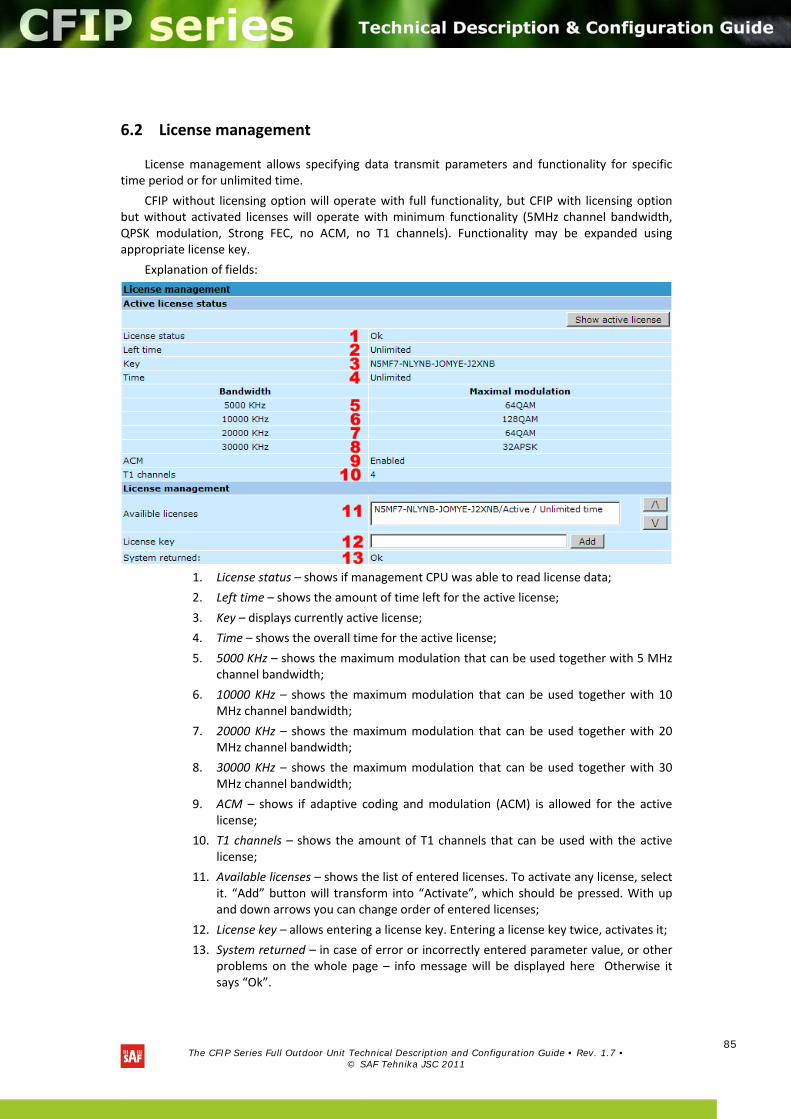
The CFIP Series Full Outdoor Unit Technical Description and Configuration Guide • Rev. 1.7 •
© SAF Tehnika JSC 2011
85
6.2 License management
License management allows specifying data transmit parameters and functionality for specific time period or for unlimited time.
CFIP without licensing option will operate with full functionality, but CFIP with licensing option but without activated licenses will operate with minimum functionality (5MHz channel bandwidth, QPSK modulation, Strong FEC, no ACM, no T1 channels). Functionality may be expanded using appropriate license key.
Explanation of fields:
1. License status – shows if management CPU was able to read license data;
2. Left time – shows the amount of time left for the active license;
3. Key – displays currently active license;
4. Time – shows the overall time for the active license;
5. 5000 KHz – shows the maximum modulation that can be used together with 5 MHz channel bandwidth;
6. 10000 KHz – shows the maximum modulation that can be used together with 10 MHz channel bandwidth;
7. 20000 KHz – shows the maximum modulation that can be used together with 20 MHz channel bandwidth;
8. 30000 KHz – shows the maximum modulation that can be used together with 30 MHz channel bandwidth;
9. ACM – shows if adaptive coding and modulation (ACM) is allowed for the active license;
10. T1 channels – shows the amount of T1 channels that can be used with the active license;
11. Available licenses – shows the list of entered licenses. To activate any license, select it. “Add” button will transform into “Activate”, which should be pressed. With up and down arrows you can change order of entered licenses;
12. License key – allows entering a license key. Entering a license key twice, activates it;
13. System returned – in case of error or incorrectly entered parameter value, or other problems on the whole page – info message will be displayed here Otherwise it says “Ok”.
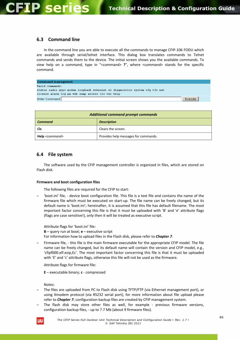
The CFIP Series Full Outdoor Unit Technical Description and Configuration Guide • Rev. 1.7 •
© SAF Tehnika JSC 2011
86
6.3 Command line
In the command line you are able to execute all the commands to manage CFIP‐106 FODU which are available through serial/telnet interface. This dialog box translates commands to Telnet commands and sends them to the device. The initial screen shows you the available commands. To view help on a command, type in “<command> ?”, where <command> stands for the specific command.
6.4 File system
The software used by the CFIP management controller is organized in files, which are stored on Flash disk.
Firmware and boot configuration files
The following files are required for the CFIP to start:
– ‘boot.ini’ file, ‐ device boot configuration file. This file is a text file and contains the name of the firmware file which must be executed on start‐up. The file name can be freely changed, but its default name is ‘boot.ini’; hereinafter, it is assumed that this file has default filename. The most important factor concerning this file is that it must be uploaded with ‘B’ and ‘e’ attribute flags (flags are case sensitive!), only then it will be treated as executive script.
Attribute flags for ‘boot.ini’ file: B – query run at boot; e – executive script For information how to upload files in the Flash disk, please refer to Chapter 7.
– Firmware file, ‐ this file is the main firmware executable for the appropriate CFIP model. The file name can be freely changed, but its default name will contain the version and CFIP model, e.g., ‘cfipf000.elf.ezip,Ec’. The most important factor concerning this file is that it must be uploaded with ‘E’ and ‘c’ attribute flags, otherwise this file will not be used as the firmware.
Attribute flags for firmware file:
E – executable binary; c ‐ compressed
Notes:
– The files are uploaded from PC to Flash disk using TFTP/FTP (via Ethernet management port), or using Xmodem protocol (via RS232 serial port), for more information about file upload please refer to Chapter 7; configuration backup files are created by CFIP management system.
– The flash disk may store other files as well, for example ‐ previous firmware versions, configuration backup files, ‐ up to 7.7 Mb (about 9 firmware files).
Additional command prompt commands
Command Description
Cls Clears the screen.
Help <command> Provides help messages for commands.
The CFIP Series Full Outdoor Unit Technical Description and Configuration Guide • Rev. 1.7 •
© SAF Tehnika JSC 2011
87
– The attribute flags for files are case sensitive.
– The file names can be changed, but it is very important that the file has the necessary attribute flags; otherwise, the file will not be used either as firmware, or as ‘boot.ini’ type file.
– There are no file extensions in the file system; either file, when edited, is treated as ASCII text file.
– When uploading the file, if the Flash disk stores the file with the same filename as for the file being uploaded, it will be overwritten with the new file.
Configuration backup files
Using ‘cfg backup <filename>’ command, the user can create the backup file of the current CFIP configuration. The configuration backup file is a text file and, when created, contains the current configuration script, ‐ the same configuration script that is stored in EEPROM. Please refer to Chapter 7 for more information on configuration script.
The configuration backup files are stored on Flash disk, where they can be edited or downloaded to PC. The backup configuration file can be applied in run‐time, by consecutively entering ‘cfg restore <filename>’ and ‘cfg run’ commands. Note: the configuration restored from file is not stored in EEPROM and, therefore it will be lost during CFIP restart. To save it in EEPROM use ‘write’ command.
The user can create and store several configuration files to quickly revert to other CFIP site configurations.
Working with files
The following commands are intended to operate with files stored on Flash disk in the management controller.
tfs ls Displays the list of files stored on the Flash disk and the number of bytes, both free and used by these files.
‘tfs dir’ can also be used.
tfs cat <filename> Displays the contents of the text file.
‘tfs type’ can also be used.
tfs edit <file> Edits the specified file. This command is applied for editing configuration backup files and boot configuration file (boot.ini). For example,
edit boot.ini,Be
– file ‘boot.ini’ will be opened for editing. ‘Be’ specifies that this file will be saved with attributes ‘B’ and ‘e’. If boot.ini file is intended to be modified, it should always be opened specifying ‘B’ and ‘e’ flags as in the example above, this will ensure that file is saved with these attributes (flags).
To close the file and save changes press Ctrl+Z, to close the file without saving changes press Ctrl+Q.
The configuration backup files do not require specific attributes.
tfs del <filename> Deletes the specified file from Flash disk.
‘tfs rm’ can also be used.
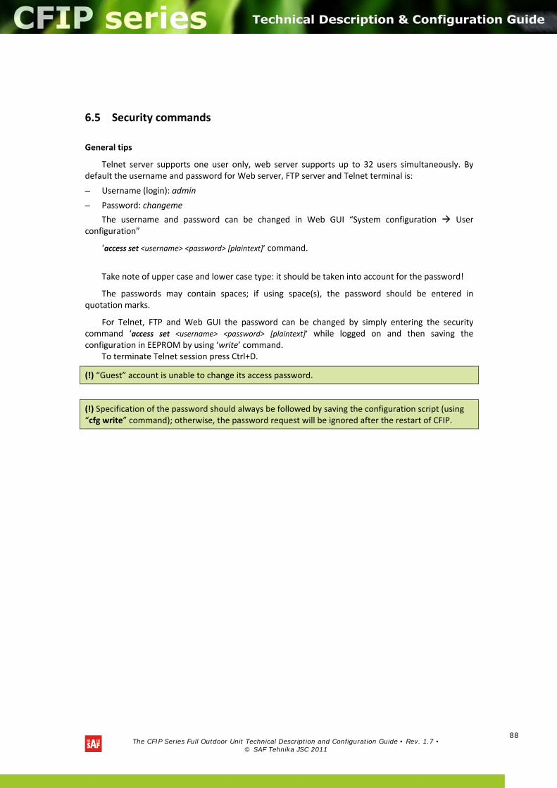
The CFIP Series Full Outdoor Unit Technical Description and Configuration Guide • Rev. 1.7 •
© SAF Tehnika JSC 2011
88
6.5 Security commands
General tips
Telnet server supports one user only, web server supports up to 32 users simultaneously. By default the username and password for Web server, FTP server and Telnet terminal is:
– Username (login): admin
– Password: changeme
The username and password can be changed in Web GUI “System configuration User configuration”
‘access set <username> <password> [plaintext]’ command.
Take note of upper case and lower case type: it should be taken into account for the password!
The passwords may contain spaces; if using space(s), the password should be entered in quotation marks.
For Telnet, FTP and Web GUI the password can be changed by simply entering the security command ‘access set <username> <password> [plaintext]’ while logged on and then saving the configuration in EEPROM by using ‘write’ command.
To terminate Telnet session press Ctrl+D.
(!) “Guest” account is unable to change its access password.
(!) Specification of the password should always be followed by saving the configuration script (using “cfg write” command); otherwise, the password request will be ignored after the restart of CFIP.
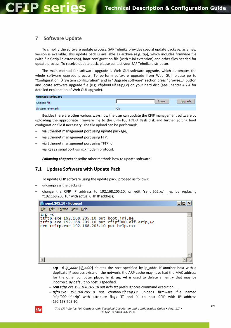
The CFIP Series Full Outdoor Unit Technical Description and Configuration Guide • Rev. 1.7 •
© SAF Tehnika JSC 2011
89
7 Software Update
To simplify the software update process, SAF Tehnika provides special update package, as a new version is available. This update pack is available as archive (e.g. zip), which includes firmware file (with *.elf.ezip,Ec extension), boot configuration file (with *.ini extension) and other files needed for update process. To receive update pack, please contact your SAF Tehnika distributor.
The main method for software upgrade is Web GUI software upgrade, which automates the whole software upgrade process. To perform software upgrade from Web GUI, please go to “Configuration System configuration” and in “Upgrade software” section press “Browse…” button and locate software upgrade file (e.g. cfipf000.elf.ezip,Ec) on your hard disc (see Chapter 4.2.4 for detailed explanation of Web GUI upgrade).
Besides there are other various ways how the user can update the CFIP management software by uploading the appropriate firmware file to the CFIP‐106 FODU flash disk and further editing boot configuration file if necessary. The file upload can be performed:
– via Ethernet management port using update package,
– via Ethernet management port using FTP,
– via Ethernet management port using TFTP, or
via RS232 serial port using Xmodem protocol. Following chapters describe other methods how to update software.
7.1 Update Software with Update Pack
To update CFIP software using the update pack, proceed as follows:
– uncompress the package;
– change the CFIP IP address to 192.168.205.10, or edit ‘send.205.xx’ files by replacing “192.168.205.10” with actual CFIP IP address;
– arp –d ip_addr [if_addr] deletes the host specified by ip_addr. If another host with a duplicate IP address exists on the network, the ARP cache may have had the MAC address for the other computer placed in it. arp –d is used to delete an entry that may be incorrect. By default no host is specified.
– rem ttftp.exe 192.168.205.10 put help.txt prefix ignores command execution
– ttftp.exe 192.168.205.10 put cfipf000.elf.ezip,Ec uploads firmware file named ‘cfipf000.elf.ezip’ with attribute flags ‘E’ and ‘c’ to host CFIP with IP address 192.168.205.10.
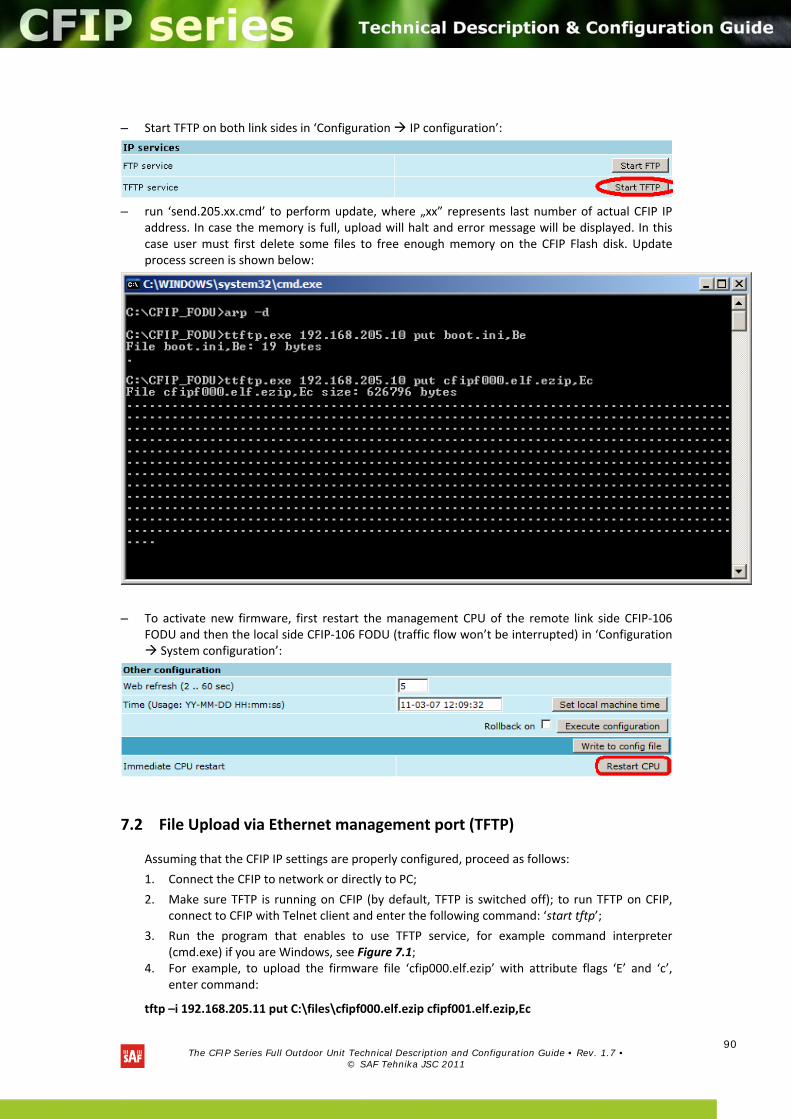
The CFIP Series Full Outdoor Unit Technical Description and Configuration Guide • Rev. 1.7 •
© SAF Tehnika JSC 2011
90
– Start TFTP on both link sides in ‘Configuration IP configuration’:
– run ‘send.205.xx.cmd’ to perform update, where „xx” represents last number of actual CFIP IP address. In case the memory is full, upload will halt and error message will be displayed. In this case user must first delete some files to free enough memory on the CFIP Flash disk. Update process screen is shown below:
– To activate new firmware, first restart the management CPU of the remote link side CFIP‐106 FODU and then the local side CFIP‐106 FODU (traffic flow won’t be interrupted) in ‘Configuration System configuration’:
7.2 File Upload via Ethernet management port (TFTP)
Assuming that the CFIP IP settings are properly configured, proceed as follows:
1. Connect the CFIP to network or directly to PC;
2. Make sure TFTP is running on CFIP (by default, TFTP is switched off); to run TFTP on CFIP, connect to CFIP with Telnet client and enter the following command: ‘start tftp’;
3. Run the program that enables to use TFTP service, for example command interpreter (cmd.exe) if you are Windows, see Figure 7.1;
4. For example, to upload the firmware file ‘cfip000.elf.ezip’ with attribute flags ‘E’ and ‘c’, enter command:
tftp –i 192.168.205.11 put C:\files\cfipf000.elf.ezip cfipf001.elf.ezip,Ec
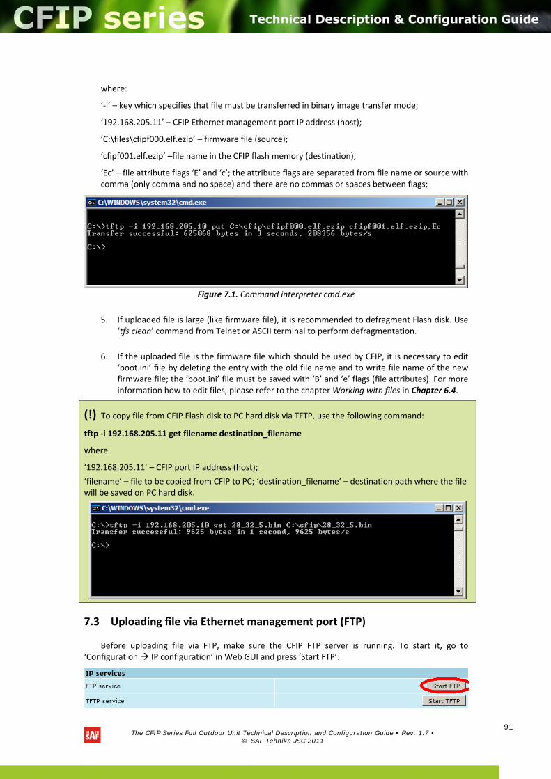
The CFIP Series Full Outdoor Unit Technical Description and Configuration Guide • Rev. 1.7 •
© SAF Tehnika JSC 2011
91
where:
‘‐i’ – key which specifies that file must be transferred in binary image transfer mode;
‘192.168.205.11’ – CFIP Ethernet management port IP address (host);
‘C:\files\cfipf000.elf.ezip’ – firmware file (source);
‘cfipf001.elf.ezip’ –file name in the CFIP flash memory (destination);
‘Ec’ – file attribute flags ‘E’ and ‘c’; the attribute flags are separated from file name or source with comma (only comma and no space) and there are no commas or spaces between flags;
Figure 7.1. Command interpreter cmd.exe
5. If uploaded file is large (like firmware file), it is recommended to defragment Flash disk. Use ‘tfs clean’ command from Telnet or ASCII terminal to perform defragmentation.
6. If the uploaded file is the firmware file which should be used by CFIP, it is necessary to edit
‘boot.ini’ file by deleting the entry with the old file name and to write file name of the new firmware file; the ‘boot.ini’ file must be saved with ‘B’ and ‘e’ flags (file attributes). For more information how to edit files, please refer to the chapter Working with files in Chapter 6.4.
7.3 Uploading file via Ethernet management port (FTP)
Before uploading file via FTP, make sure the CFIP FTP server is running. To start it, go to ‘Configuration IP configuration’ in Web GUI and press ‘Start FTP’:
(!) To copy file from CFIP Flash disk to PC hard disk via TFTP, use the following command:
tftp ‐i 192.168.205.11 get filename destination_filename
where
‘192.168.205.11’ – CFIP port IP address (host);
‘filename’ – file to be copied from CFIP to PC; ‘destination_filename’ – destination path where the file will be saved on PC hard disk.
The CFIP Series Full Outdoor Unit Technical Description and Configuration Guide • Rev. 1.7 •
© SAF Tehnika JSC 2011
92
1. Open command window.
2. Start FTP client by entering “ftp” command (“ftp>” prompt will appear).
3. Connect to CFIP FTP server using command “open <CFIP_IP_address>”. Type in username and password when prompted (by default username is admin and password is changeme).
4. Enter the command “type binary” to make sure the binary transfer mode is selected.
5. Use command “send <local file> <remote file>, <flags>” to upload files to CFIP Flash disk. For example:
send c:\boot.ini boot.ini,Be
Use flags ‘E’ and ‘c’ if the file is a firmware file; if the file is a boot configuration file (boot.ini), the flags must be ‘B’ and ‘e’ (‘Be’); the flags for configuration backup files may not be specified.
Use command “ls” to list files on CFIP flash disk.
Use command “delete <filename>” to delete the file from the CFIP Flash disk.
6. Proceed with steps 5. and 6. in Chapter 7.1.
You can also use any preferable FTP client if you wish.
7.4 Uploading file via serial port (Xmodem)
File upload via serial port takes much longer time compared to use of TFTP and should be used only in case Ethernet connection with the CFIP management system is not available, or does not start normally.
1. Connect the ASCII console to the CFIP serial port, make connection with the following properties: Bits per second: 19200; Data bits: 8; Parity: none; Stop bits: 1; Flow control: none; if using ‘Hyper Terminal’ program, please refer to Chapter 2.3.1 for information how to make a connection.
2. Type ‘restartcpu’ and, while CFIP is booting, press any key when ‘boot.ini?’ prompt appears. This will stop executing script in ‘boot.ini’ file and the CFIP will remain in MicroMonitor mode. This is the system start‐up mode which loads the management system firmware;
Note: While you are in MicroMonitor mode, the ‘uMON>’ prompt will be displayed, instead of normal prompt with CFIP name (default ‘SAF>’).
3. In MicroMonitor mode enter the following command:
xmodem –cd –F <file_path‐no_flags> ‐f Ec
where
<file_path‐no_flags> ‐ file name with no flags specified
‘Ec’ – file flags, in case the file is firmware file ‐ ‘E’ and ‘c’ flags must be used; if the file is boot configuration file (boot.ini), the flags must be ‘Be’ (‘B’ and ‘e’); the flags for configuration backup files may not be specified, in that case the command will be
xmodem –cd –F <file_path‐no_flags>
After xmodem command execution, proceed to the next step.
4. Use terminal emulation software with file upload function, such as Hyper Terminal (in Windows) to upload the firmware file to CFIP as binary image (use binary transfer mode), using Xmodem protocol.
If you are using Hyper Terminal, proceed as follows: from menu select ‘TransferSend File…’, then select file and in ‘protocol’ box select Xmodem protocol and press ‘Send’ button. The following box should appear:
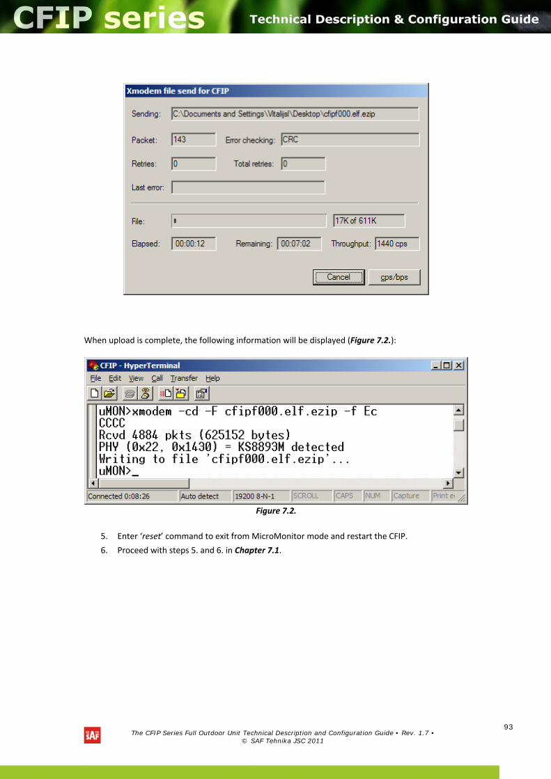
The CFIP Series Full Outdoor Unit Technical Description and Configuration Guide • Rev. 1.7 •
© SAF Tehnika JSC 2011
93
When upload is complete, the following information will be displayed (Figure 7.2.):
Figure 7.2.
5. Enter ‘reset’ command to exit from MicroMonitor mode and restart the CFIP.
6. Proceed with steps 5. and 6. in Chapter 7.1.
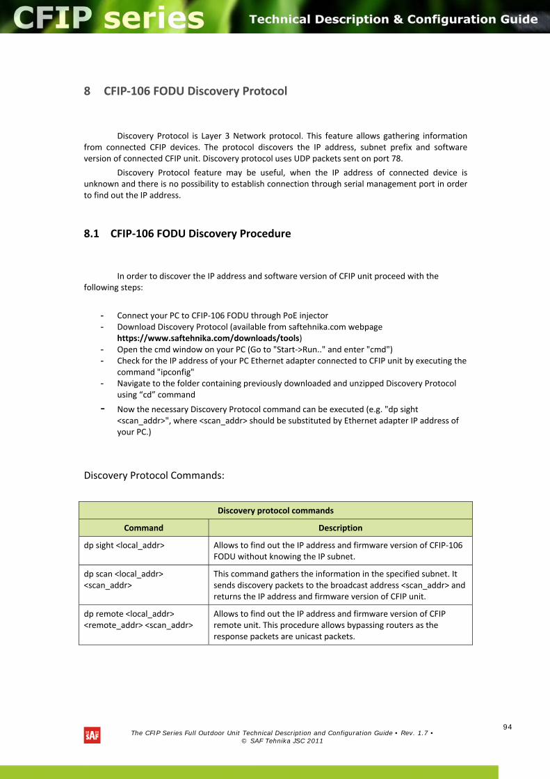
The CFIP Series Full Outdoor Unit Technical Description and Configuration Guide • Rev. 1.7 •
© SAF Tehnika JSC 2011
94
8 CFIP‐106 FODU Discovery Protocol
Discovery Protocol is Layer 3 Network protocol. This feature allows gathering information
from connected CFIP devices. The protocol discovers the IP address, subnet prefix and software version of connected CFIP unit. Discovery protocol uses UDP packets sent on port 78.
Discovery Protocol feature may be useful, when the IP address of connected device is unknown and there is no possibility to establish connection through serial management port in order to find out the IP address.
8.1 CFIP‐106 FODU Discovery Procedure
In order to discover the IP address and software version of CFIP unit proceed with the
following steps:
- Connect your PC to CFIP‐106 FODU through PoE injector - Download Discovery Protocol (available from saftehnika.com webpage
https://www.saftehnika.com/downloads/tools) - Open the cmd window on your PC (Go to "Start‐>Run.." and enter "cmd") - Check for the IP address of your PC Ethernet adapter connected to CFIP unit by executing the
command "ipconfig" - Navigate to the folder containing previously downloaded and unzipped Discovery Protocol
using “cd” command
- Now the necessary Discovery Protocol command can be executed (e.g. "dp sight <scan_addr>", where <scan_addr> should be substituted by Ethernet adapter IP address of your PC.)
Discovery Protocol Commands:
Discovery protocol commands
Command Description
dp sight <local_addr> Allows to find out the IP address and firmware version of CFIP‐106 FODU without knowing the IP subnet.
dp scan <local_addr> <scan_addr>
This command gathers the information in the specified subnet. It sends discovery packets to the broadcast address <scan_addr> and returns the IP address and firmware version of CFIP unit.
dp remote <local_addr> <remote_addr> <scan_addr>
Allows to find out the IP address and firmware version of CFIP remote unit. This procedure allows bypassing routers as the response packets are unicast packets.
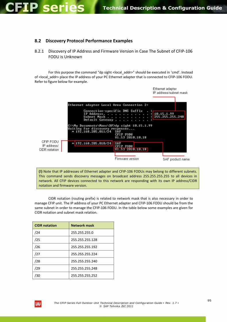
The CFIP Series Full Outdoor Unit Technical Description and Configuration Guide • Rev. 1.7 •
© SAF Tehnika JSC 2011
95
8.2 Discovery Protocol Performance Examples
8.2.1 Discovery of IP Address and Firmware Version in Case The Subnet of CFIP‐106 FODU is Unknown
For this purpose the command “dp sight <local_addr>” should be executed in ‘cmd’. Instead of <local_addr> place the IP address of your PC Ethernet adapter that is connected to CFIP‐106 FODU. Refer to figure below for example.
CIDR notation (routing prefix) is related to network mask that is also necessary in order to manage CFIP unit. The IP address of your PC Ethernet adapter and CFIP‐106 FODU should be from the same subnet in order to manage the CFIP‐106 FODU. In the table below some examples are given for CIDR notation and subnet mask relation.
CIDR notation Network mask
/24 255.255.255.0
/25 255.255.255.128
/26 255.255.255.192
/27 255.255.255.224
/28 255.255.255.240
/29 255.255.255.248
/30 255.255.255.252
(!) Note that IP addresses of Ethernet adapter and CFIP‐106 FODUs may belong to different subnets. This command sends discovery messages on broadcast address 255.255.255.255 to all devices in network. All CFIP devices connected to this network are responding with its own IP address/CIDR notation and firmware version.
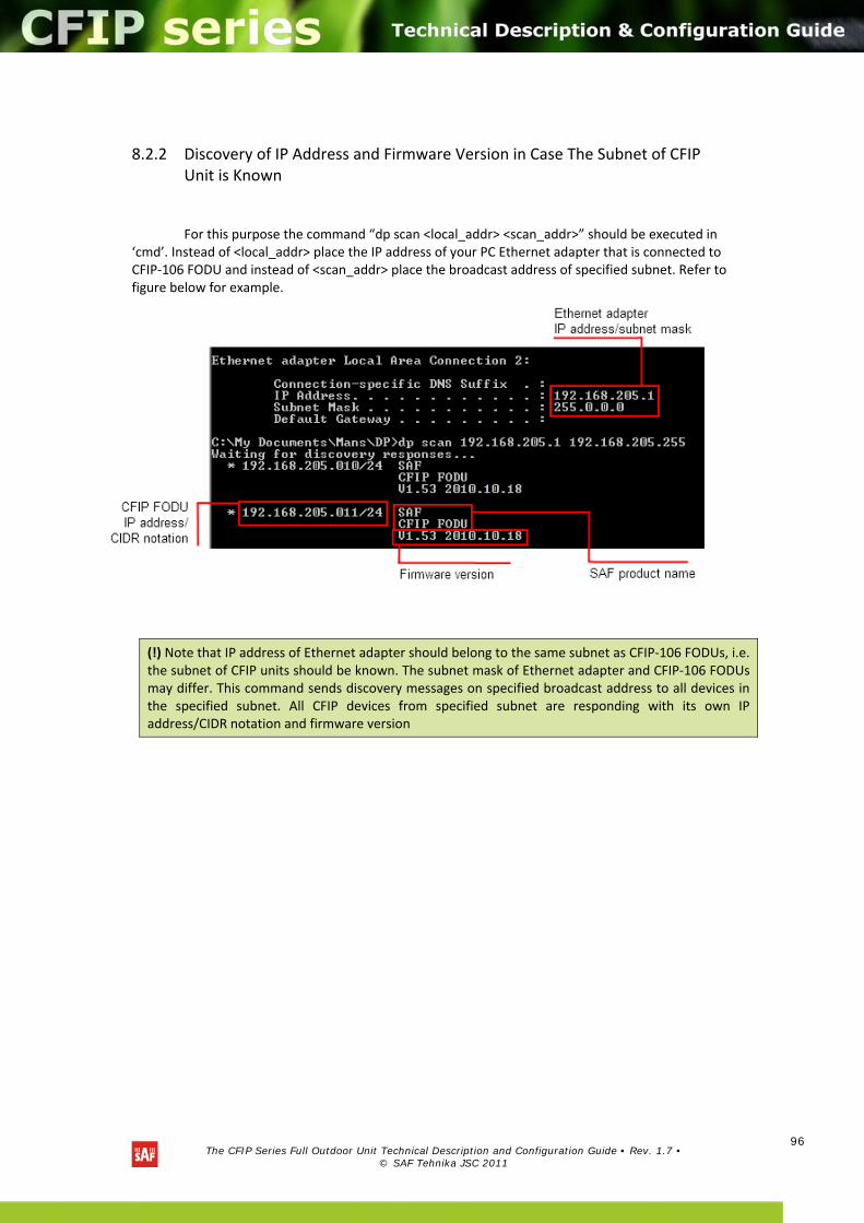
The CFIP Series Full Outdoor Unit Technical Description and Configuration Guide • Rev. 1.7 •
© SAF Tehnika JSC 2011
96
8.2.2 Discovery of IP Address and Firmware Version in Case The Subnet of CFIP Unit is Known
For this purpose the command “dp scan <local_addr> <scan_addr>” should be executed in ‘cmd’. Instead of <local_addr> place the IP address of your PC Ethernet adapter that is connected to CFIP‐106 FODU and instead of <scan_addr> place the broadcast address of specified subnet. Refer to figure below for example.
(!) Note that IP address of Ethernet adapter should belong to the same subnet as CFIP‐106 FODUs, i.e. the subnet of CFIP units should be known. The subnet mask of Ethernet adapter and CFIP‐106 FODUs may differ. This command sends discovery messages on specified broadcast address to all devices in the specified subnet. All CFIP devices from specified subnet are responding with its own IP address/CIDR notation and firmware version
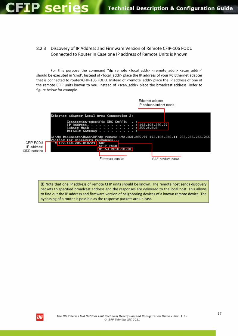
The CFIP Series Full Outdoor Unit Technical Description and Configuration Guide • Rev. 1.7 •
© SAF Tehnika JSC 2011
97
8.2.3 Discovery of IP Address and Firmware Version of Remote CFIP‐106 FODU Connected to Router In Case one IP address of Remote Units is Known
For this purpose the command “dp remote <local_addr> <remote_addr> <scan_addr>” should be executed in ‘cmd’. Instead of <local_addr> place the IP address of your PC Ethernet adapter that is connected to router/CFIP‐106 FODU. Instead of <remote_addr> place the IP address of one of the remote CFIP units known to you. Instead of <scan_addr> place the broadcast address. Refer to figure below for example.
(!) Note that one IP address of remote CFIP units should be known. The remote host sends discovery packets to specified broadcast address and the responses are delivered to the local host. This allows to find out the IP address and firmware version of neighboring devices of a known remote device. The bypassing of a router is possible as the response packets are unicast.
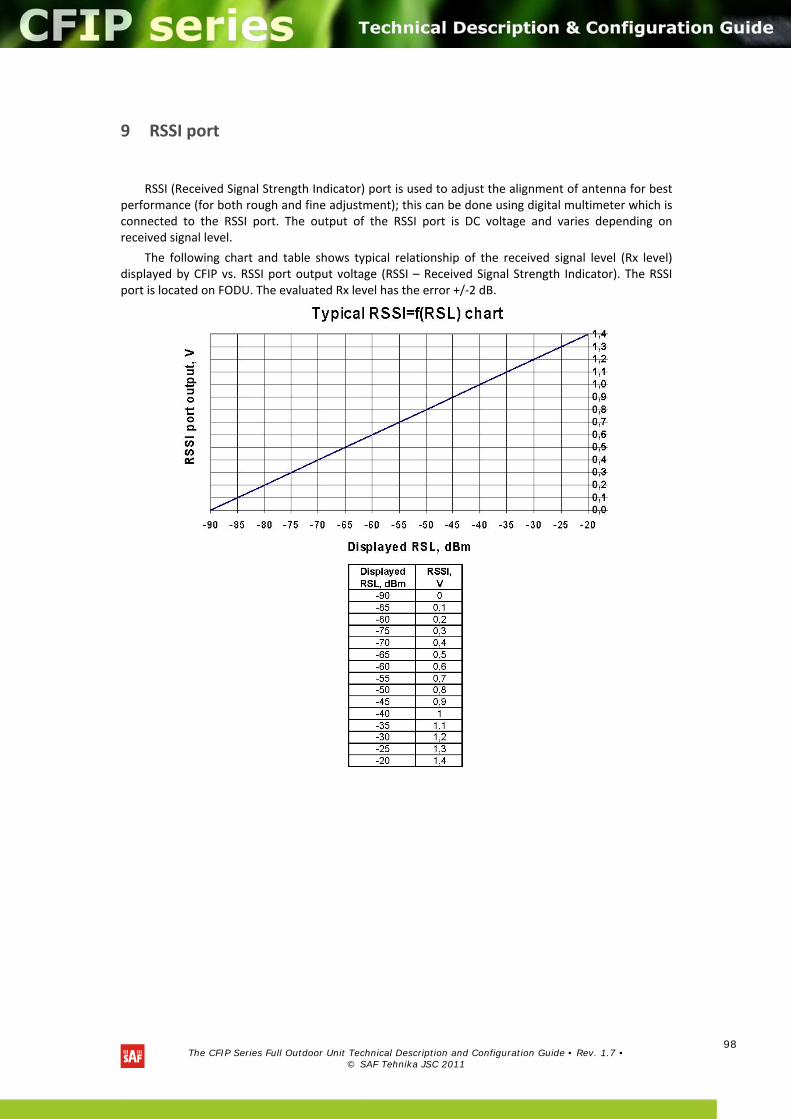
The CFIP Series Full Outdoor Unit Technical Description and Configuration Guide • Rev. 1.7 •
© SAF Tehnika JSC 2011
98
9 RSSI port
RSSI (Received Signal Strength Indicator) port is used to adjust the alignment of antenna for best performance (for both rough and fine adjustment); this can be done using digital multimeter which is connected to the RSSI port. The output of the RSSI port is DC voltage and varies depending on received signal level.
The following chart and table shows typical relationship of the received signal level (Rx level) displayed by CFIP vs. RSSI port output voltage (RSSI – Received Signal Strength Indicator). The RSSI port is located on FODU. The evaluated Rx level has the error +/‐2 dB.
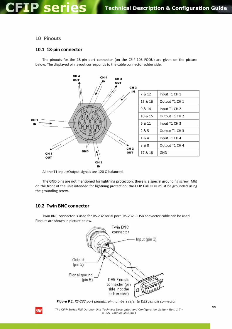
The CFIP Series Full Outdoor Unit Technical Description and Configuration Guide • Rev. 1.7 •
© SAF Tehnika JSC 2011
99
10 Pinouts
10.1 18‐pin connector
The pinouts for the 18‐pin port connector (on the CFIP‐106 FODU) are given on the picture below. The displayed pin layout corresponds to the cable connector solder side.
All the T1 Input/Output signals are 120 Ω balanced. The GND pins are not mentioned for lightning protection; there is a special grounding screw (M6)
on the front of the unit intended for lightning protection; the CFIP Full ODU must be grounded using the grounding screw.
10.2 Twin BNC connector
Twin BNC connector is used for RS‐232 serial port. RS‐232 – USB convector cable can be used. Pinouts are shown in picture below.
Figure 9.1. RS‐232 port pinouts, pin numbers refer to DB9 female connector
7 & 12 Input T1 CH 1
13 & 16 Output T1 CH 1
9 & 14 Input T1 CH 2
10 & 15 Output T1 CH 2
6 & 11 Input T1 CH 3
2 & 5 Output T1 CH 3
1 & 4 Input T1 CH 4
3 & 8 Output T1 CH 4
17 & 18 GND
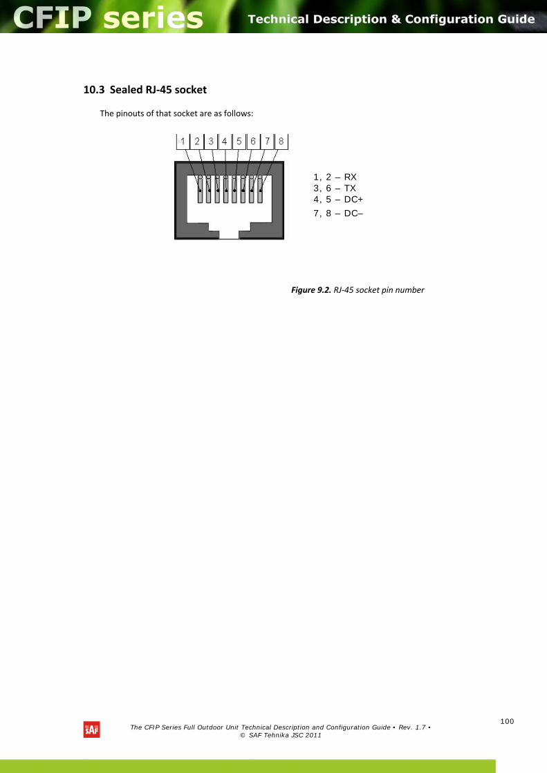
The CFIP Series Full Outdoor Unit Technical Description and Configuration Guide • Rev. 1.7 •
© SAF Tehnika JSC 2011
100
10.3 Sealed RJ‐45 socket
The pinouts of that socket are as follows:
Figure 9.2. RJ‐45 socket pin number
1, 2 – RX 3, 6 – TX 4, 5 – DC+
7, 8 – DC–
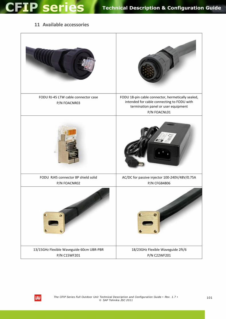
The CFIP Series Full Outdoor Unit Technical Description and Configuration Guide • Rev. 1.7 •
© SAF Tehnika JSC 2011
101
11 Available accessories
FODU RJ‐45 LTW cable connector case
P/N FOACNR03
FODU 18‐pin cable connector, hermetically sealed, intended for cable connecting to FODU with
termination panel or user equipment
P/N FOACNL01
FODU RJ45 connector 8P shield solid
P/N FOACNR02
AC/DC for passive injector 100‐240V/48V/0.75A
P/N CFGB4806
13/15GHz Flexible Waveguide 60cm UBR‐PBR
P/N C15WF201
18/23GHz Flexible Waveguide 2ft/6
P/N C22WF201
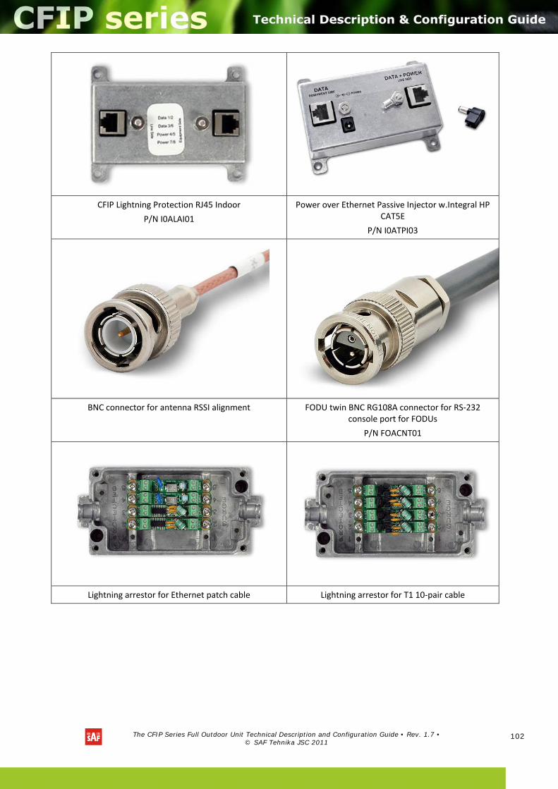
The CFIP Series Full Outdoor Unit Technical Description and Configuration Guide • Rev. 1.7 •
© SAF Tehnika JSC 2011
102
CFIP Lightning Protection RJ45 Indoor
P/N I0ALAI01
Power over Ethernet Passive Injector w.Integral HP CAT5E
P/N I0ATPI03
BNC connector for antenna RSSI alignment FODU twin BNC RG108A connector for RS‐232 console port for FODUs
P/N FOACNT01
Lightning arrestor for Ethernet patch cable Lightning arrestor for T1 10‐pair cable

The CFIP Series Full Outdoor Unit Technical Description and Configuration Guide • Rev. 1.7 •
© SAF Tehnika JSC 2011
103
FODU cable TWIN BNC ‐ DB9 (2m)
P/N FOACTW01 CFIP Lightning Protection RJ45 Outdoor
P/N I0ALAO01
Test equipment 13/15 GHz
(See the list of available test equipment below)
Coaxial attenuator 40 dB
P/N CLA40A01
FODU UTP cable cat5 4P outdoor solid
P/N FOACET02
CFIP‐TP4 terminal power injector w.4T1
P/N I0GTP401
CFIP‐106 FODU Mounting Bracket
(for 1xFODU P/N: CLGRFB05; for 2xFODU P/N: CLGRFB06)
O‐ring ‐ rubber gasket to be fitted between 0.25m antenna and FODU
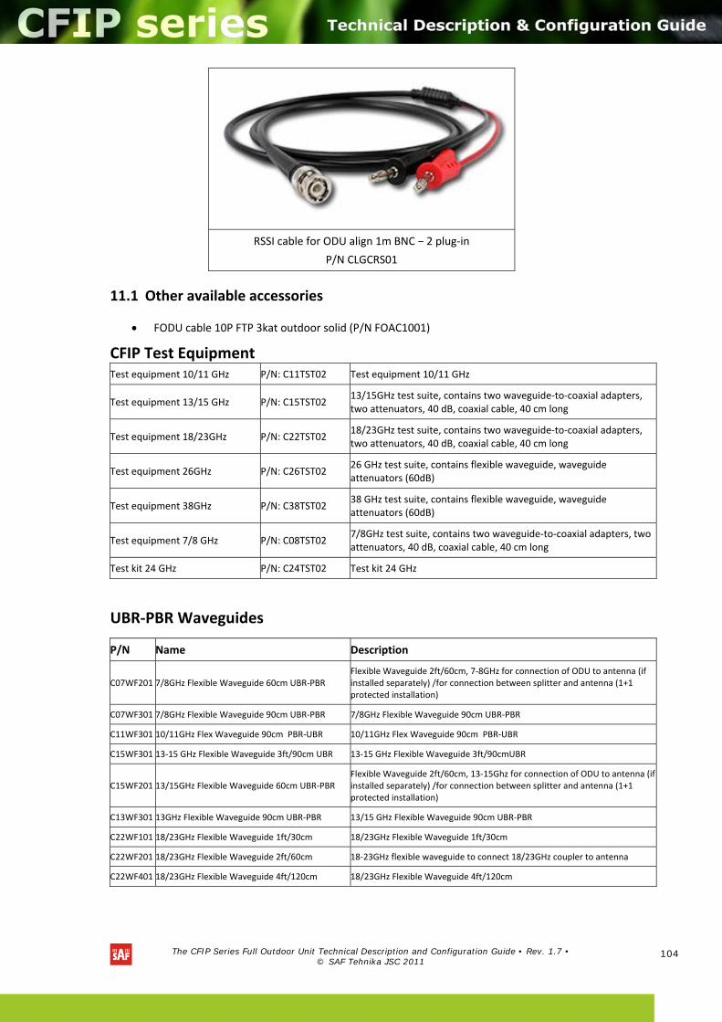
The CFIP Series Full Outdoor Unit Technical Description and Configuration Guide • Rev. 1.7 •
© SAF Tehnika JSC 2011
104
RSSI cable for ODU align 1m BNC − 2 plug‐in
P/N CLGCRS01
11.1 Other available accessories
FODU cable 10P FTP 3kat outdoor solid (P/N FOAC1001)
CFIP Test Equipment Test equipment 10/11 GHz P/N: C11TST02 Test equipment 10/11 GHz
Test equipment 13/15 GHz P/N: C15TST02 13/15GHz test suite, contains two waveguide‐to‐coaxial adapters, two attenuators, 40 dB, coaxial cable, 40 cm long
Test equipment 18/23GHz P/N: C22TST02 18/23GHz test suite, contains two waveguide‐to‐coaxial adapters, two attenuators, 40 dB, coaxial cable, 40 cm long
Test equipment 26GHz P/N: C26TST02 26 GHz test suite, contains flexible waveguide, waveguide attenuators (60dB)
Test equipment 38GHz P/N: C38TST02 38 GHz test suite, contains flexible waveguide, waveguide attenuators (60dB)
Test equipment 7/8 GHz P/N: C08TST02 7/8GHz test suite, contains two waveguide‐to‐coaxial adapters, two attenuators, 40 dB, coaxial cable, 40 cm long
Test kit 24 GHz P/N: C24TST02 Test kit 24 GHz
UBR‐PBR Waveguides
P/N Name Description
C07WF201 7/8GHz Flexible Waveguide 60cm UBR‐PBR Flexible Waveguide 2ft/60cm, 7‐8GHz for connection of ODU to antenna (if installed separately) /for connection between splitter and antenna (1+1 protected installation)
C07WF301 7/8GHz Flexible Waveguide 90cm UBR‐PBR 7/8GHz Flexible Waveguide 90cm UBR‐PBR
C11WF301 10/11GHz Flex Waveguide 90cm PBR‐UBR 10/11GHz Flex Waveguide 90cm PBR‐UBR
C15WF301 13‐15 GHz Flexible Waveguide 3ft/90cm UBR 13‐15 GHz Flexible Waveguide 3ft/90cmUBR
C15WF201 13/15GHz Flexible Waveguide 60cm UBR‐PBR Flexible Waveguide 2ft/60cm, 13‐15Ghz for connection of ODU to antenna (if installed separately) /for connection between splitter and antenna (1+1 protected installation)
C13WF301 13GHz Flexible Waveguide 90cm UBR‐PBR 13/15 GHz Flexible Waveguide 90cm UBR‐PBR
C22WF101 18/23GHz Flexible Waveguide 1ft/30cm 18/23GHz Flexible Waveguide 1ft/30cm
C22WF201 18/23GHz Flexible Waveguide 2ft/60cm 18‐23GHz flexible waveguide to connect 18/23GHz coupler to antenna
C22WF401 18/23GHz Flexible Waveguide 4ft/120cm 18/23GHz Flexible Waveguide 4ft/120cm
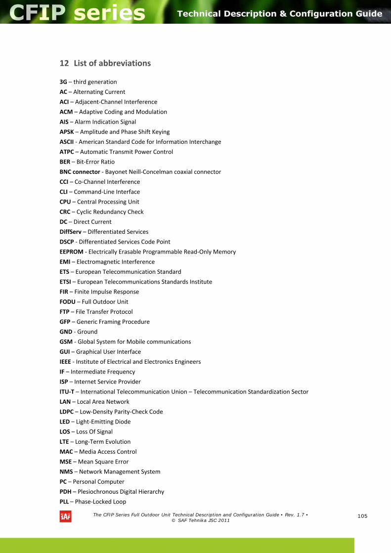
The CFIP Series Full Outdoor Unit Technical Description and Configuration Guide • Rev. 1.7 •
© SAF Tehnika JSC 2011
105
12 List of abbreviations
3G – third generation
AC – Alternating Current
ACI – Adjacent‐Channel Interference
ACM – Adaptive Coding and Modulation
AIS – Alarm Indication Signal
APSK – Amplitude and Phase Shift Keying
ASCII ‐ American Standard Code for Information Interchange
ATPC – Automatic Transmit Power Control
BER – Bit‐Error Ratio
BNC connector ‐ Bayonet Neill‐Concelman coaxial connector
CCI – Co‐Channel Interference
CLI – Command‐Line Interface
CPU – Central Processing Unit
CRC – Cyclic Redundancy Check
DC – Direct Current
DiffServ – Differentiated Services
DSCP ‐ Differentiated Services Code Point
EEPROM ‐ Electrically Erasable Programmable Read‐Only Memory
EMI – Electromagnetic Interference
ETS – European Telecommunication Standard
ETSI – European Telecommunications Standards Institute
FIR – Finite Impulse Response
FODU – Full Outdoor Unit
FTP – File Transfer Protocol
GFP – Generic Framing Procedure
GND ‐ Ground
GSM ‐ Global System for Mobile communications
GUI – Graphical User Interface
IEEE ‐ Institute of Electrical and Electronics Engineers
IF – Intermediate Frequency
ISP – Internet Service Provider
ITU‐T – International Telecommunication Union – Telecommunication Standardization Sector
LAN – Local Area Network
LDPC – Low‐Density Parity‐Check Code
LED – Light‐Emitting Diode
LOS – Loss Of Signal
LTE – Long‐Term Evolution
MAC – Media Access Control
MSE – Mean Square Error
NMS – Network Management System
PC – Personal Computer
PDH – Plesiochronous Digital Hierarchy
PLL – Phase‐Locked Loop

The CFIP Series Full Outdoor Unit Technical Description and Configuration Guide • Rev. 1.7 •
© SAF Tehnika JSC 2011
106
PoE ‐ Power over Ethernet
QAM ‐ Quadrature amplitude modulation
QoS – Quality of Service
QPSK ‐ Quadrature Phase‐Shift Keying
RAM – Random Access Memory
RSL – Received Signal Level
RSSI – Received Signal Strength Indicator
Rx – Receive
SNMP ‐ Simple Network Management Protocol
SNR – Signal‐to‐Noise Ratio
STM‐1 – Synchronous Transport Module – 1
STP – Spanning Tree Protocol
TCP/IP – Internet Protocol Suite (Transmission Control Protocol / Internet Protocol)
TDM – Time‐Division Multiplexing
TFTP – Trivial File Transfer Protocol
TM – Tide Mark
TP – Twisted Pair
TS – Threshold Seconds
Tx – Transmission
UART – Universal Asynchronous Receiver/Transmitter
USB – Universal Serial Bus
UTP – Unshielded Twisted Pair
VLAN – Virtual Local Area Network
WAN – Wide Area Network

The CFIP Series Full Outdoor Unit Technical Description and Configuration Guide • Rev. 1.7 •
© SAF Tehnika JSC 2011
107
13 SAF Tehnika JSC Contacts
SAF Tehnika A/S technical support can be reached by:
- Email: [email protected]
- Telephone: +371 67046840
- Fax: +371 67046809