Embed Size (px)
Citation preview
INSTRUCTIONSAND
PARTS MANUAL
CGW-5000 COMPACT GIRTH WELDER
A DIVISION OF WELD TOOLING CORPORATION
280 TECHNOLOGY DRIVE CANONSBURG, PENNSYLVANIA 15317-9564 USA PHONE: 412-331-1776 http://www.bugo.com FAX: 412-331- 0383
Please record your equipment identification information below for future reference. This information can be found on your machine nameplate.
Model Number:
Serial Number:
Date of Purchase:
Whenever you request replacement parts or information on this equipment, always supply the information you have recorded above.
LIT-CGW-5000-IPM-0319
Bug-O Systems is committed to empowering our customers by providing operator controlled mechanized solutions for their welding, cutting and custom applications.
2
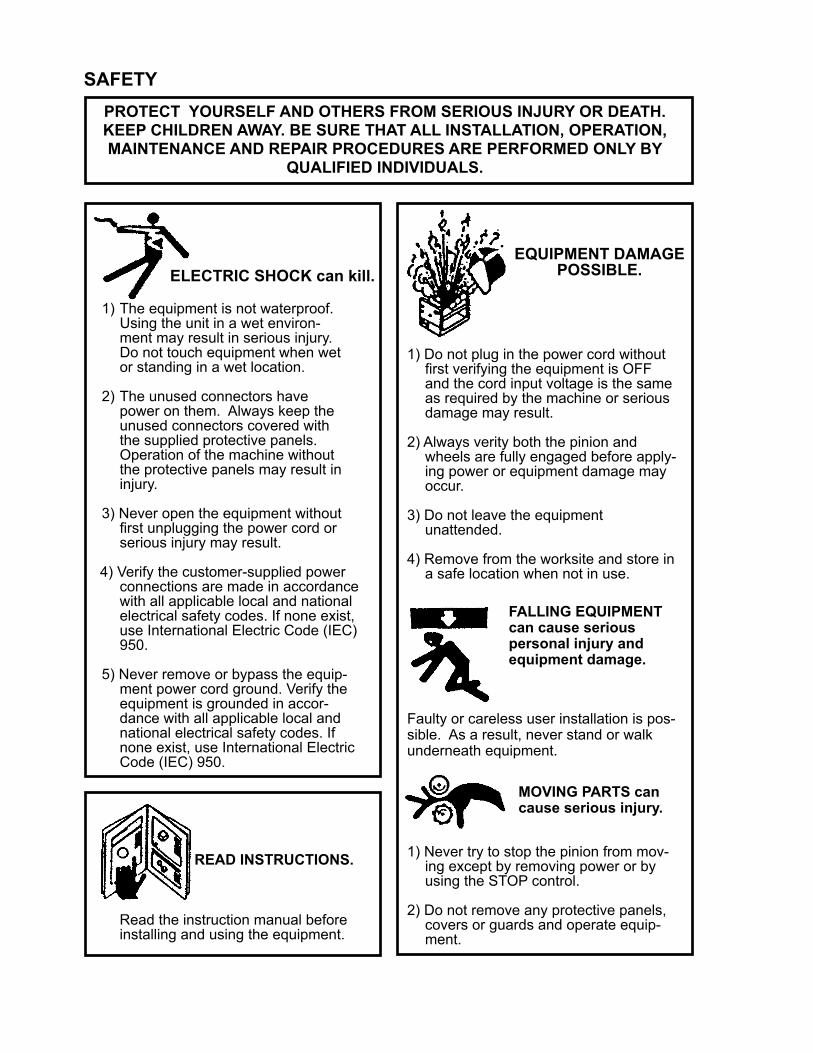
SAFETY PROTECT YOURSELF AND OTHERS FROM SERIOUS INJURY OR DEATH. KEEP CHILDREN AWAY. BE SURE THAT ALL INSTALLATION, OPERATION, MAINTENANCE AND REPAIR PROCEDURES ARE PERFORMED ONLY BY
QUALIFIED INDIVIDUALS.
EQUIPMENT DAMAGE POSSIBLE.ELECTRIC SHOCK can kill.
1) The equipment is not waterproof.Using the unit in a wet environ-
ment may result in serious injury. Do not touch equipment when wet or standing in a wet location.
2) The unused connectors havepower on them. Always keep theunused connectors covered withthe supplied protective panels.Operation of the machine withoutthe protective panels may result ininjury.
3) Never open the equipment withoutfirst unplugging the power cord orserious injury may result.
4) Verify the customer-supplied powerconnections are made in accordancewith all applicable local and nationalelectrical safety codes. If none exist,use International Electric Code (IEC)950.
5) Never remove or bypass the equip- ment power cord ground. Verify the
equipment is grounded in accor- dance with all applicable local and
national electrical safety codes. If none exist, use International Electric Code (IEC) 950.
READ INSTRUCTIONS.
Read the instruction manual before installing and using the equipment.
1) Do not plug in the power cord withoutfirst verifying the equipment is OFFand the cord input voltage is the sameas required by the machine or seriousdamage may result.
2) Always verity both the pinion andwheels are fully engaged before apply-
ing power or equipment damage may occur.
3) Do not leave the equipmentunattended.
4) Remove from the worksite and store ina safe location when not in use.
1) Never try to stop the pinion from mov- ing except by removing power or by
using the STOP control.
2) Do not remove any protective panels,covers or guards and operate equip-
ment.
MOVING PARTS can cause serious injury.
FALLING EQUIPMENT can cause serious personal injury and equipment damage.
Faulty or careless user installation is pos-sible. As a result, never stand or walk underneath equipment.

3
PRECAUTIONS:
1) Some plasma or welding cables are strong sources of high frequency interference. NEVER lay a plasma or welding cable across the controls of the machine.
2) Always physically separate the plasma or welding cable leads from the machine cables. For example, the plasma or welding cable leads should NEVER be bundled with a pendant cable or the machine power cord. Maxi- mize the separation between any machine cables and the plasma or welding cables.
3) Strictly follow the grounding procedures specified for the plasma or welding unit. NOTE: Some plasma and welding units produce exceptionally large amounts of high frequency noise. They may require a grounding rod be driven into the earth within six feet (2 meters) of the plasma or welding unit to become compatible with an automatic cutting or welding process.
4) If the high frequency is produced using a spark gap, adjust the points so the gap is as small as possible. The larger the gap, the higher the voltage and the higher the interference.
5) Some plasma or welding units will inject high frequency interference into the AC power line. Use separate power line branches whenever possible to power the plasma or welding source and the machine. Do not plug them into the same outlet box.
6) High frequency noise may enter the machine through the plasma or welding supply remote contactor leads. Some plasma and welding sources can produce noise spikes of up to several thousand volts. These sources are not compatible with automated cutting and welding equipment. It is recom- mended that the remote contactor leads on these plasma or welding sources not be connected to the machine. An alternate solution is to purchase a separate remote contactor isolation box.
HIGH FREQUENCY WARNINGS
WARNING: HIGH FREQUENCY CAN EFFECT MACHINE OPERATION AND THEREFORE, WELD QUALITY.
SPECIAL PRECAUTIONS ARE REQUIRED WHEN USING PLASMA, TIG OR ANY WELDING PROCESS THAT USES HIGH FREQUENCY
TO STRIKE AN ARC.
Read the precautions below before installing and using the equipment.
4
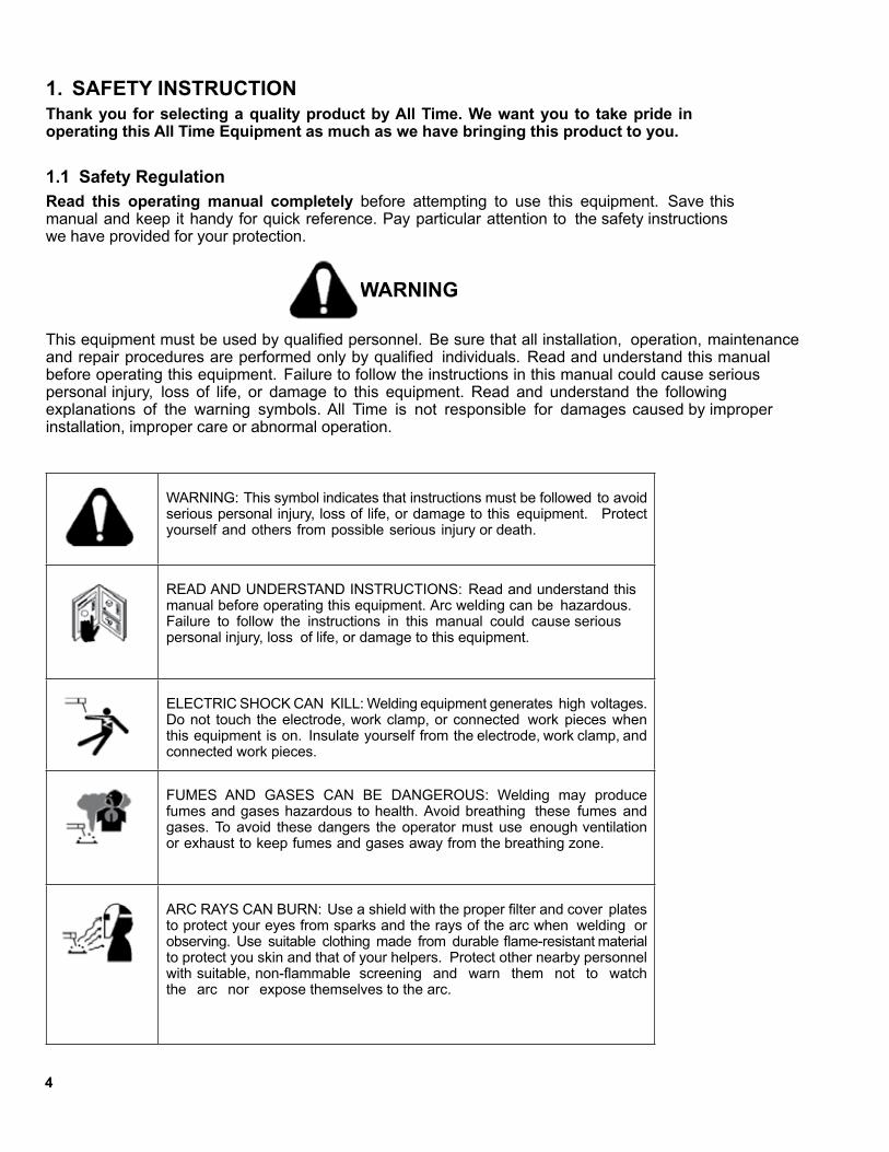
1. SAFETY INSTRUCTIONThank you for selecting a quality product by All Time. We want you to take pride in operating this All Time Equipment as much as we have bringing this product to you.
1.1 Safety RegulationRead this operating manual completely before attempting to use this equipment. Save this manual and keep it handy for quick reference. Pay particular attention to the safety instructions we have provided for your protection.
WARNING
This equipment must be used by qualified personnel. Be sure that all installation, operation, maintenance and repair procedures are performed only by qualified individuals. Read and understand this manual before operating this equipment. Failure to follow the instructions in this manual could cause serious personal injury, loss of life, or damage to this equipment. Read and understand the following explanations of the warning symbols. All Time is not responsible for damages caused by improper installation, improper care or abnormal operation.
WARNING: This symbol indicates that instructions must be followed to avoid serious personal injury, loss of life, or damage to this equipment. Protect yourself and others from possible serious injury or death.
READ AND UNDERSTAND INSTRUCTIONS: Read and understand this manual before operating this equipment. Arc welding can be hazardous. Failure to follow the instructions in this manual could cause serious personal injury, loss of life, or damage to this equipment.
ELECTRIC SHOCK CAN KILL: Welding equipment generates high voltages. Do not touch the electrode, work clamp, or connected work pieces when this equipment is on. Insulate yourself from the electrode, work clamp, and connected work pieces.
FUMES AND GASES CAN BE DANGEROUS: Welding may produce fumes and gases hazardous to health. Avoid breathing these fumes and gases. To avoid these dangers the operator must use enough ventilation or exhaust to keep fumes and gases away from the breathing zone.
ARC RAYS CAN BURN: Use a shield with the proper filter and cover plates to protect your eyes from sparks and the rays of the arc when welding or observing. Use suitable clothing made from durable flame-resistant material to protect you skin and that of your helpers. Protect other nearby personnel with suitable, non-flammable screening and warn them not to watch the arc nor expose themselves to the arc.

5
WELDING SPARKS CAN CAUSE FIRE OR EXPLOSION: Remove firehazards from the welding area and have a fire extinguisher readily available. Welding sparks and hot materials from the welding process can easily go through small cracks and openings to adjacent areas. Do not weld on any tanks, drums, containers, or material until the proper steps have been taken to insure that no flammable or toxic vapors will be present. Never operate this equipment when flammable gases, vapors or liquid combustiblesare present.
ELECTRICALLY POWERED EQUIPMENT: Turn off input power using the disconnect switch at the fuse box before working on this equipment. Ground this equipment in accordance with local electricalregulations.
ELECTRICALLY POWERED EQUIPMENT: Regularly inspect the input, electrode, and work clamp cables. If any insulation damage exists replace the cable immediately. No not place the electrode holder directly on the welding table or any other surface in contact with the work clamp to avoid the risk of accidental arc ignition.
ELECTRIC AND MAGNETIC FIELDS MAY BE DANGEROUS: Electric current flowing through any conductor creates electrical and magnetic fields (EMF). EMF fields may interfere with some pacemakers, and welders having a pacemaker should consult their physician before operating this equipment.
CYLINDER MAY EXPLODE IF DAMAGED: Use only compressed gas cylinders containing the correct shielding gas for the process used and properly operating regulators designed for the gas and pressure used. Always keep cylinders in an upright position securely chained to a fixed support. Do not move or transport gas cylinders with the protection cap removed. Do not allow the electrode, electrode holder, work clamp or any other electrically live part to touch a gas cylinder. Gas cylinders must be located away from areas where they may be subjected to physical damage or the welding process including sparks and heat sources.
WELDED MATERIALS CAN BURN: Welding generates a large amount of heat. Hot surfaces and materials in work area can cause serious burns. Use gloves and pliers when touching or moving materials in the work area.
1.2 Warning Plate
6
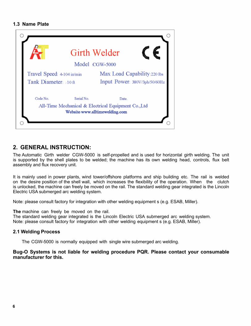
1.3 Name Plate
2. GENERAL INSTRUCTION:The Automatic Girth welder CGW-5000 is self-propelled and is used for horizontal girth welding. The unit is supported by the shell plates to be welded; the machine has its own welding head, controls, flux belt assembly and flux recovery unit.
It is mainly used in power plants, wind tower/offshore platforms and ship building etc. The rail is welded on the desire position of the shell wall, which increases the flexibility of the operation. When the clutch is unlocked, the machine can freely be moved on the rail. The standard welding gear integrated is the Lincoln Electric USA submerged arc welding system.
Note: please consult factory for integration with other welding equipment s (e.g. ESAB, Miller).
The machine can freely be moved on the rail.The standard welding gear integrated is the Lincoln Electric USA submerged arc welding system.Note: please consult factory for integration with other welding equipment s (e.g. ESAB, Miller).
2.1 Welding Process
The CGW-5000 is normally equipped with single wire submerged arc welding.
Bug-O Systems is not liable for welding procedure PQR. Please contact your consumable manufacturer for this.

7
4.............. Safety Instruction4 ......... Safety Regulation5 ......... Warning Plate6 ......... Name Plate
6.............. General Instruction
8.............. 3. Technical Specifications8 ......... 3.1 Specification8 ......... 3.2 Machine Dimensions
9.............. 4. Key Components9 ......... 4.1 Main Frame9 ......... 4.2 Motor Drives
10 ......... 4.3 Weld Head Assembly11 ......... 4.4 Control13 ......... 4.5 Flux Recovery14 ......... 4.6 Electrical Cabinet
14............ 5. Installation14 ......... 5.1 Frame Setup16 ......... 5.2 Master Control Connections16 ......... 5.3 Input Connection
16............ 6. Operation
17............ 7. Welding
18............ 8. Troubleshooting
20............ 9. Maintenance
22............ 10. Electrical Drawing
23............ 11. Technical Diagram
TABLE OF CONTENTS
CGW-5000 COMPACT GIRTH WELDERINSTRUCTIONS AND PARTS MANUAL
PAGE
8
3. TECHNICAL SPECIFICATIONS:
3.1 Specification
1. Input Power: 380V/3ph/50/60Hz* Consult factory for non-standard power input
2. Max Load Capability: 220 lbs.
3. Operation temperature: 14 degrees F to 122 degrees F; Relative humidity: >90%;
4. Environmental protection: IP23 grade: F
5. Tank diameter operation range: >10'
6. Operation tank shell plate width: >30 inches
7. Travel Speed: 4-104 in/min
* Models and specifications subject to change without notice.
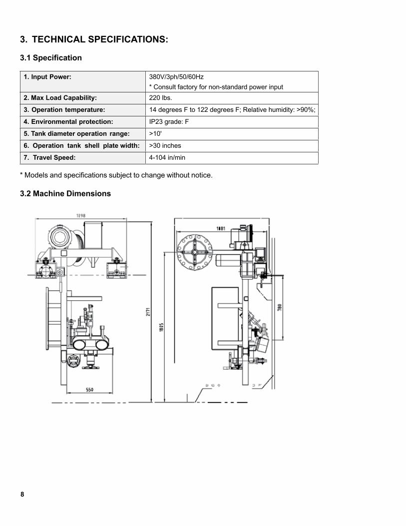
3.2 Machine Dimensions
9
4. KEY COMPONENTS
4.1 Main Frame
The main frame of the girth welder is constructed of structural steel and square tube members. The frame contains two hardened steel flanged drive wheels manually adjusted to ride tank diameters down to a minimum of 10'.
Guide wheel assembly at the lower end of the frame simplifies the loading/unloading the machine on the tank.
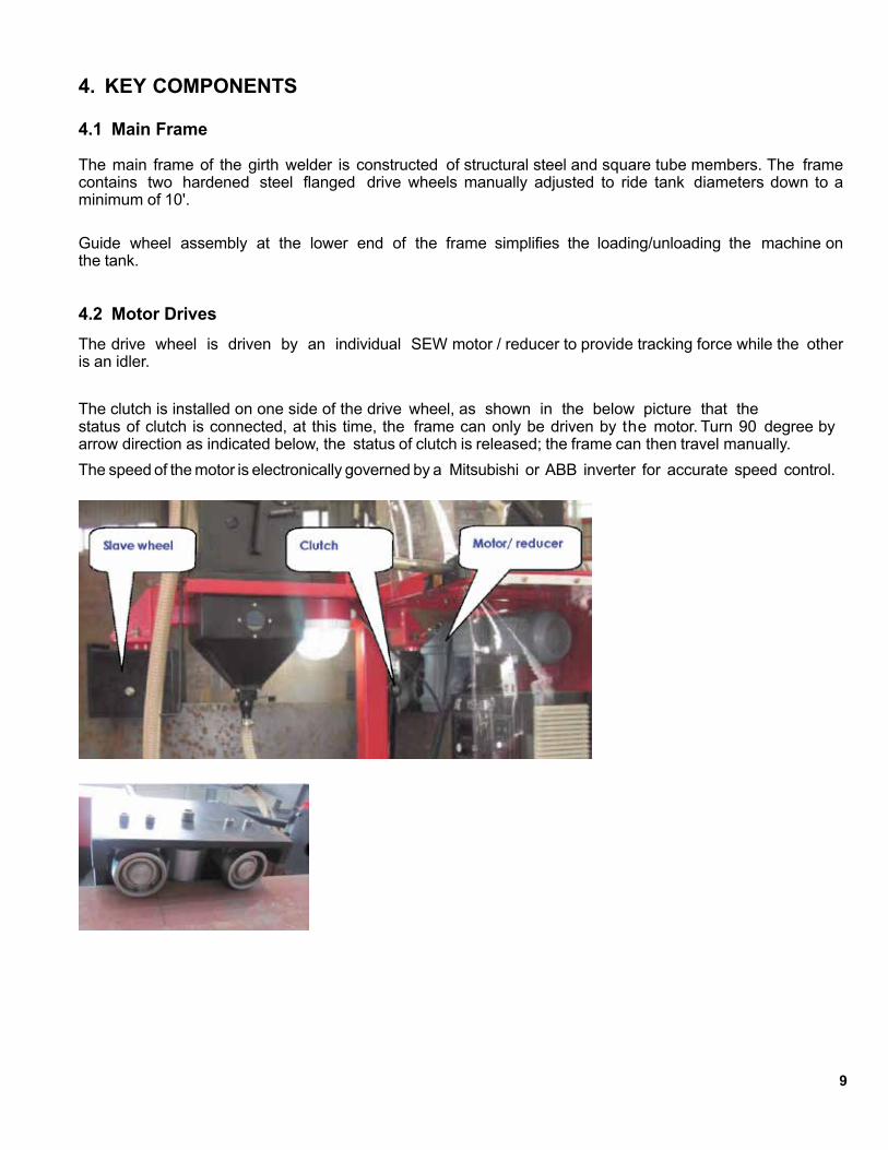
4.2 Motor DrivesThe drive wheel is driven by an individual SEW motor / reducer to provide tracking force while the other is an idler.
The clutch is installed on one side of the drive wheel, as shown in the below picture that thestatus of clutch is connected, at this time, the frame can only be driven by the motor. Turn 90 degree by arrow direction as indicated below, the status of clutch is released; the frame can then travel manually.The speed of the motor is electronically governed by a Mitsubishi or ABB inverter for accurate speed control.

10
AC inverter:1. Single-phase 220VAC input voltage2. Automatic lift in torsion, 150% lift torsion in 6Hz.3. Fully programmed and calibrated in factory4. Soft PWM, running in low noise5. 15 speed, PID, 4-20 MA input6. Provides RS-485 communication
Caution: The inverter drive inside the CGW control is pre-programmed before the girth welder is delivered to users on site, please consult factory if re-programming is required.
The SEW motors and reducer require minimal maintenance with advantages of low noise and vibration, with 96% high efficiency through the reducer. It consists of a high rigid housing and spur gear; all parts are precisely machined with minimum tolerance for accurate travel mechanism.
4.3 Weld Head Assembly
The CGW-5000 weld head is mounted on a manual cross slide system, which allows the operator complete control of wire placement and joint tracking.
The CGW-5000 master control houses the electronic travel Inverter drive and associated control relays; it provides a mean of integrated control of all the accessories of the girth welder (e.g. flux vacuum).
Due to the lack of visibility of the submerged arc welding process, a laser pointer is mounted on the nozzle to provide a position reference for operator while welding.
11
4.4 Control
4.4.1 Welding controlLincoln USA POWER NA-3 welding control is standard power source to the girth welder. It is mounted at the right hand side of the main frame for operator easy access, directly on top of the NA-3 control is the CGW-5000 master control.
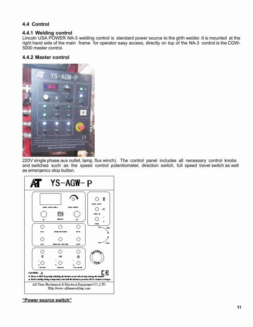
4.4.2 Master control
220V single phase aux outlet, lamp, flux winch). The control panel includes all necessary control knobs and switches such as the speed control potentiometer, direction switch, full speed travel switch as well as emergency stop button.
“Power source switch”

12
Turns on main power of the control
“Left-Stop-Right” travel direction switch (SA3)
Placing the switch in the selected side causes the machine to move in that particular welding direction.
For automatic travel, the travel switch on the NA3 must be in the travel position. To operate manually, the switch must be in hand position.
“Speed potentiometer” (SA2)
Accurately adjust speed travel speeds (cm/min) Inverter ON/OFF
Push buttons switch to power on / off the inverter.
CAUTION: Switching the inverter on and off in the girth welder. The speed can be monitored at the control display.
US version of the All Time CGW-5000 would be programmed to display travel speed in IPM (inch per minute)
Normal / full speed travel switch
Activate girth welder full speed travel when the weld gear is set to “manual” mode or “off”.
“Flux recovery vacuum” switch (SA4)
Turns on power of the vacuum for flux recovery short interval could cause damage to the inverter. It is recommended to switch on the inverter again at least 3 minutes after is it turned off.
“Lighting switch”
Switch on the hurricane lamp for night operation.
Emergency stopPush button stops all electronic functions including welding and travel.
13
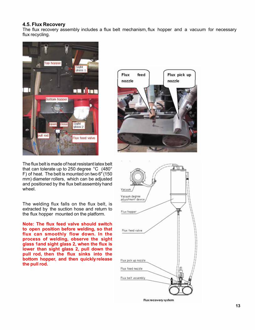
4.5. Flux RecoveryThe flux recovery assembly includes a flux belt mechanism, flux hopper and a vacuum for necessary flux recycling.
The flux belt is made of heat resistant latex belt that can tolerate up to 250 degree °C (480° F) of heat. The belt is mounted on two 6" (150 mm) diameter rollers, which can be adjusted and positioned by the flux belt assembly hand wheel.
The welding flux falls on the flux belt, is extracted by the suction hose and return to the flux hopper mounted on the platform.
Note: The flux feed valve should switch to open position before welding, so that flux can smoothly flow down. In the process of welding, observe the sight glass 1and sight glass 2, when the flux is lower than sight glass 2, pull down the pull rod, then the flux sinks into the bottom hopper, and then quickly release the pull rod.

14
The All Time CGW is equipped with a heavy duty blower type vacuum for multi-shifts continuous operation. Such vacuum system can be configured as follow to suitable various operation requirements:
(a) Flux Hopper/Separation Chamber and Vacuum mounted on top of the operator platform (standard)
(b) Flux Hopper/Separation Chamber and Vacuum mounted on frame roof (vacuum system would move upward along with the roof and drive section of the CGW)
Vacuum degree adjustment deviceUndo the butterfly bolt, and turning the outside sleeve to adjust the vacuum degree in the flux hopper.
4.6 Electrical CabinetThe electrical cabinet of the girth welder is installed inside the frame.
5. INSTALLATIONCorrect installation and setup is critical to ensure proper operation of the CGW and welding equipment.
5.1 Frame SetupThe installation of the rail onto the shell wall refers to the drawing.
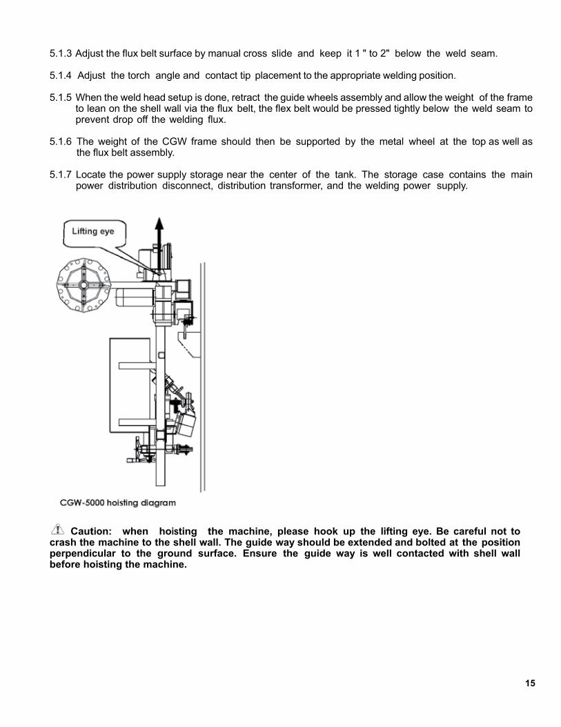
When all components of the CGW are in place, hook up the lifting eye at the roof of the CGW with crane and lift the frame off the ground, then hang drive wheels on the rail and lower it down, so the flanged wheel would land on the rail.
5.1.1 The guide wheels should be extended approximate to the maximum extension with the hand wheel, and then bolted at the position perpendicular to the ground surface, it provides a moving support to the frame and prevent impact between the flux belt systems and weld head to the shell plate.
5.1.2 When the CGW frame is secured straddle on the rail, retract the support guide wheel by hand wheel and bolt the orientation of the support wheel to the horizontal position.
15
5.1.3 Adjust the flux belt surface by manual cross slide and keep it 1 " to 2" below the weld seam.
5.1.4 Adjust the torch angle and contact tip placement to the appropriate welding position.
5.1.5 When the weld head setup is done, retract the guide wheels assembly and allow the weight of the frame to lean on the shell wall via the flux belt, the flex belt would be pressed tightly below the weld seam to prevent drop off the welding flux.
5.1.6 The weight of the CGW frame should then be supported by the metal wheel at the top as well as the flux belt assembly.
5.1.7 Locate the power supply storage near the center of the tank. The storage case contains the main power distribution disconnect, distribution transformer, and the welding power supply.
Caution: when hoisting the machine, please hook up the lifting eye. Be careful not to crash the machine to the shell wall. The guide way should be extended and bolted at the position perpendicular to the ground surface. Ensure the guide way is well contacted with shell wall before hoisting the machine.

16
5.2 Master Control Connections
There are nine sets of receptacles (eight sets for some models) at the side of the control panel, each receptacle is DIFFERENT and only can mate with the correct connectors of the below components:
a) Flux Vacuumb) Main Powerc) 220VAC/1ph aux output (for electrical hand tools such as grinder)d) Laser Pointere) Lightingf) NA-3 Control on/offg) Motor Driveh) Flux Lifting Winchi) Cooling Fan
5.3 Input Connection
WARNING! Only a qualified electrician should connect the Input leads to the GIRTH WELDERI. Connections should be made in accordance with all local and national electrical codes.
Connect the three phase supply line (380V for standard GIRTH WELDER, 240V / 440V for special version) to L1, L2, L3 and ground to the input lug of the 3-phase circuit breaker inside the electrical cabinet as illustrated to the input supply connection diagram below.
The electrical cabinet also consists of a step down transformer and a secondary circuit breaker for 1 phase / 220V input to the GIRTH WELDER. The GIRTH WELDER are shipped connected for the input voltage specified for the destination of the machine in factory.
NOTE: Turning main input power of the machine OFF before performing reconnects procedure. Failure to do so will result in damage to the machine.
6. OPERATION6.1 Connect the weld and ground cables
6.2 Power up the main switches at the electric cabinet, verify the weld gears and drive system are functioning.
6.3 Test all the switches on the master control panel and monitor the LEDs (the LEDs are only available for the later CGW models).
NOTE: The CGW master control is powered by 220V/1ph VAC and 110V/1ph VAC please check for first time operation.
CAUTION: After switching off the inverter, please wait for at least 3 minutes before switching it on again. Quick repetitions to switch the inverter on and off could damage the inverter due to the residual voltage. Please refer to the inverter manual for details.
6.4 Check the flux vacuum is properly powered by the toggle switch at the master control, make sure enough flux is filled to the flux separator and the correct flux valves of the flux feed / recovery hoses are open.
6.5 Test the switches on the wire feeding control (e.g. Lincoln NA-3) make sure there is wire feed to the nozzle.

17
6.6 As soon as the inverter is powered up, the speed display should indicate the speed preset by the users. User can test run the CGW at the preset speed and full speed.
NOTE: When the inverter is off, the display should indicate “000” when the frame is not moving.
7. WELDING7.1 Choose the weld direction by setting the travel switch to left or right, adjust the weld speed according to the welding procedure. Set NA-3 travel switch to” hand” so the frame would travel without welding.
7.2 Set to correct CV-VV switch position inside the NA Control. Preset appropriate welding voltage / current at the NA-3 control, then switch NA-3 to “Auto”.
7.3 Release the flux valve to allow sufficient amount of flux to drop on the arc start area and cover the wire stick out.
NOTE: For models with electric flux valve option, the flux would feed automatically when the wire touches the work when the operator presses “inch down” to feed wire prior welding.
7.4 Press “start” push button of the NA-3 and the start the weld sequence (wire is slowly feed to the work, the arc strikes and weld travel begins).
7.5 During welding, operator should closely observe if the welding arc is tracking the weld joint, use the laser pointer as the position indicator and finely adjust the torch position via the manual cross slide if necessary.
7.6 When the welding operation is complete, simply press the “STOP” bottom at the NA-3 control panel and the CGW frame would stop traveling with the termination of the welding arc.
NOTE:* For safety reasons, please power off the system before disconnecting any of the control cables to the master control.
* In order to increase the consumed life of the flux belt mechanism, user is recommended to extend the support guide wheels as the mean of support when the CGW is not welding (flux belt must be firmly in contact with the shell plate during welding operation for flux recovery).
* Excessive suction force would prohibit flux feeding during the welding operation; adjust the vacuum hose valve if necessary.
7.7 If the machine is going to weld in the direction opposite of what it was previously set up for, simply shut down the manual hose valve at one side and open the hose valve at the other side.
Note: there is only one flux recovered hose for each CGW, as it allow operator to move the suction hose from one side to the other.

18
8. TROUBLESHOOTING
Problems Possible Causes Recommended Action
Improper control or feeding of welding wire
Lincoln welding control or power supply is abnormal
1. Check all fuses
2. Check Lincoln control switch is “on” and polarity switch on the power supplies must be in “+” or “-”
3. Review Lincoln service manualsand diagnose possible PCBs failures
The indication light of master control fails to ignite
1. Power supply is off2. 5 pin control cable
connector is loose
3. 5 pin control cable is bad
1. Turn on power supply2. Check 5 pin connector3. Check 5 pin control cable
Flux vacuum cannot operate
1. Bad vacuum relay in the control2. Vacuum itself is faulty
1. Replace control relay / switch2. Replace flux vacuum
Lamp is off 1. Bad lighting relay in the control
2. Control cable is loose or bad
3. Light bulb is bad
1. Replace relay / switch2. Check control cable & connector3. Replace light bulb
Electric winch does not work
1. Control cable is loose or bad
2. Winch failure
1. Check control cable & connector2. Replace winch
Main frame cannot travel
1. Bad travel direction switch2. Bad speed potentiometer3. Bad travel control relay4. Incorrect inverter setting5. Faulty inverter6. Indicator Light “TRAVEL
READY” is off
1. Replace switch2. Replace potentiometer3. Replace relay4. Check inverter setting *5. Replace inverter6. Refer to following row
19
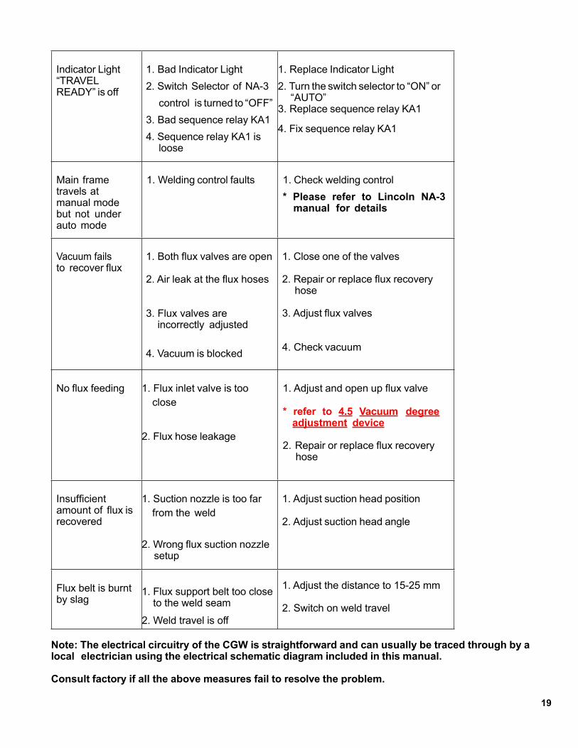
Indicator Light “TRAVEL READY” is off
1. Bad Indicator Light2. Switch Selector of NA-3
control is turned to “OFF”3. Bad sequence relay KA14. Sequence relay KA1 is
loose
1. Replace Indicator Light2. Turn the switch selector to “ON” or
“AUTO”3. Replace sequence relay KA1
4. Fix sequence relay KA1
Main frame travels at manual mode but not under auto mode
1. Welding control faults 1. Check welding control* Please refer to Lincoln NA-3 manual for details
Vacuum fails to recover flux
1. Both flux valves are open
2. Air leak at the flux hoses
3. Flux valves are incorrectly adjusted
4. Vacuum is blocked
1. Close one of the valves
2. Repair or replace flux recovery hose
3. Adjust flux valves
4. Check vacuum
No flux feeding 1. Flux inlet valve is too close
2. Flux hose leakage
1. Adjust and open up flux valve
* refer to 4.5 Vacuum degree adjustment device
2. Repair or replace flux recovery hose
Insufficient amount of flux is recovered
1. Suction nozzle is too far from the weld
2. Wrong flux suction nozzle setup
1. Adjust suction head position
2. Adjust suction head angle
Flux belt is burnt by slag
1. Flux support belt too close to the weld seam
2. Weld travel is off
1. Adjust the distance to 15-25 mm
2. Switch on weld travel
Note: The electrical circuitry of the CGW is straightforward and can usually be traced through by a local electrician using the electrical schematic diagram included in this manual.
Consult factory if all the above measures fail to resolve the problem.

20
9. MAINTENANCE9.1 Flux belt must be properly adjusted, during operation, the latex flux belt should be snug and both roll centerlines are parallel. Overly tight belt tension would cause the rollers to skew bending both rollers and cause the belt to roll off.
Flux belt is considered as consumables and should be replaced when it is worn or seriously burn.
9.2 Both SEW motors and reducers of the CGW drive system should be regularly lubricated, please refer to SEW operating instruction manuals for detail maintenance instructions.
9.3 The serrated flanged drive wheel would need to be replaced if it is worn and loose the necessary grip to keep the girth welder travel steadily on the tank shells.
9.4 Check the flux recovery system.
Clean the flux hopper filter everyday and replace the filter once every two weeks.

21
10. Electrical Drawing
Electrical Drawing (when using MAXsa-10 control box)
22
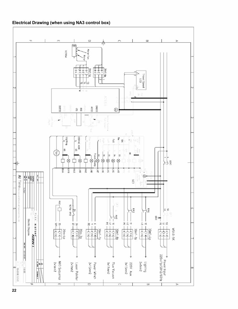
Electrical Drawing (when using NA3 control box)

23
11. Technical Diagram

24
Track for inside of tank

25
Track for outside of tank
26
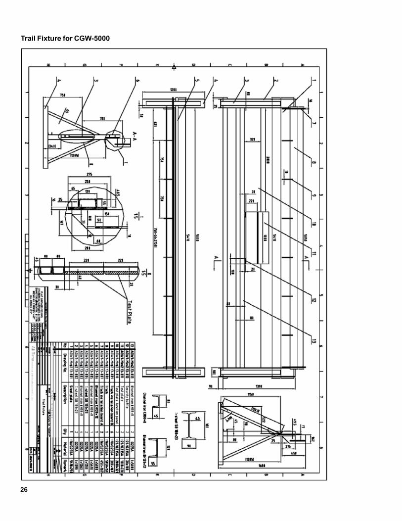
Trail Fixture for CGW-5000
27
WARRANTY
For a period of twelve (12) months from delivery, BUG-O Systems warrants to the original purchaser (does not include authorized distributors), that a new machine is free from defects in material and workmanship and agrees to repair or replace, at its option, any defective parts or machine. This warranty does not apply to machines, which after our inspection, are determined to have been damaged due to neglect, abuse, overloading, accident or improper usage. All shipping and handling charges will be paid by customer.
BUG-O Systems makes no warranty of merchantability and makes no other warranty, expressed or implied, beyond the warranty expressly set forth above. Buyer’s remedy for breach of warranty, hereunder, shall be limited to repair or replacement of non-conforming parts and machines. Under no circumstances shall consequential damages be recoverable.
HOW TO OBTAIN SERVICE:If you think this machine is not operating properly, re-read the instruction manual carefully, then call your Authorized BUG-O dealer/distributor. If he cannot give you the necessary service, write or phone us to tell us exactly what difficulty you have experienced. BE SURE to mention the MODEL and SERIAL numbers.
*Bug-O System’s warranty applies to Bug-O components only. Where other brands of power sources, wire feeders or sub components are a part of Bug-O Equipment, please refer to that specific Manufacturer’s manual for warranty specifications on their components.
Limited Warranty* Model _____________________________Serial No. __________________________Date Purchased: ____________________


![;,'t. · 2005-11-26 · bound the canmers J1t betn the fore girth and the hind girth; (s;) [i. e.] I put [or e ded], betrcoen the hind girth and the fore girth qf the camel, a cord,](https://img.pdfslide.net/doc/110x75/5f82d9f788554b6d4762941f/t-2005-11-26-bound-the-canmers-j1t-betn-the-fore-girth-and-the-hind-girth.jpg)