Embed Size (px)
DESCRIPTION
edwd
Citation preview
NTMM
By S K Mondal
Need for Unconventional Processes New materials having high strength and hardness, such as
nimonic alloys and alloys with alloying elements such as
tungsten, molybdenum, and columbium are difficult to
machine by the traditional methods.
By conventional machining the MRR reduces with an
increase in the work material hardness.
Need for development of non-traditional machining
processes which utilize other methods such as
electrochemical processes for the material removal.
Need for Unconventional Processes
Complex shapes.
A very high accuracy is desired besides the complexity of
the surface to be machined.
In Unconventional Machining Different forms of energy directly applied to the
workpiece to have shape transformation or material removal from work surface.
No chips, No lay pattern on work surface, no direct physical contact between the tool and the workpiece .
The tool material does not have to be harder than the work material.
Tool forces do not increase as the work material gets harder.
Economic metal removal rate does not decrease as the work material gets harder.
Classification of NTMM The Non-traditional Machining Methods are classified
according to the major energy sources employed in machining.
1. Thermal Energy Methods
2. Electro - Chemical Energy Method
3. Chemical Energy Methods
4. Mechanical Energy Methods
1. Thermal Energy Methods
Electrical discharge machining (EDM)
Laser beam Machining (LBM)
Plasma Arc Machining (PAM)
Electron Beam Machining(EBM)
Ion Beam Machining (IBM)
2. Electro - Chemical Energy Method
Electro-Chemical Machining (ECM)
Electro-Chemical grinding (ECG)
Electro-Chemical Honing (ECH)
Electro-Chemical Deburring (ECD)
3. Chemical Energy Methods These methods involve controlled etching of the
workpiece material in contact with a chemical solution.
Chemical Machining Method (CHM).
4. Mechanical Energy Methods
Ultra Sonic Machining (USM)
Abrasive Jet Machining (AJM)
Water Jet Machining (WJM)
Some Observations EDM has the lowest specific power requirement and can
achieve sufficient accuracy.
ECM has the highest metal removal rate, MRR.
USM and AJM have low MRR and combined with high tool wear, are used for non-metal cutting.
LBM and EBM have high penetration rates with low MRR and, therefore, are commonly used for micro drilling, sheet cutting, and welding.
CHM is used for manufacturing PCB and other shallow components.
PAM can be used for clean, rapid cuts and profiles in almost all plates upto 20 cm thick with 5o to 10o taper.
Shapes Cutting Capability The various NTMM have some special shape cutting
capability as given below:
1. Micro-machining and Drilling : LBM and EBM
2. Cavity sinking and standard Hole Drilling: EDM and
USM
3. Fine hole drilling and Contour Machining: ECM
4. Clean, rapid Cuts and Profiles: PAM
5. Shallow Pocketing: AJM
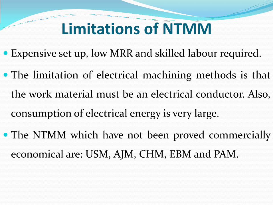
Limitations of NTMM
Expensive set up, low MRR and skilled labour required.
The limitation of electrical machining methods is that
the work material must be an electrical conductor. Also,
consumption of electrical energy is very large.
The NTMM which have not been proved commercially
economical are: USM, AJM, CHM, EBM and PAM.
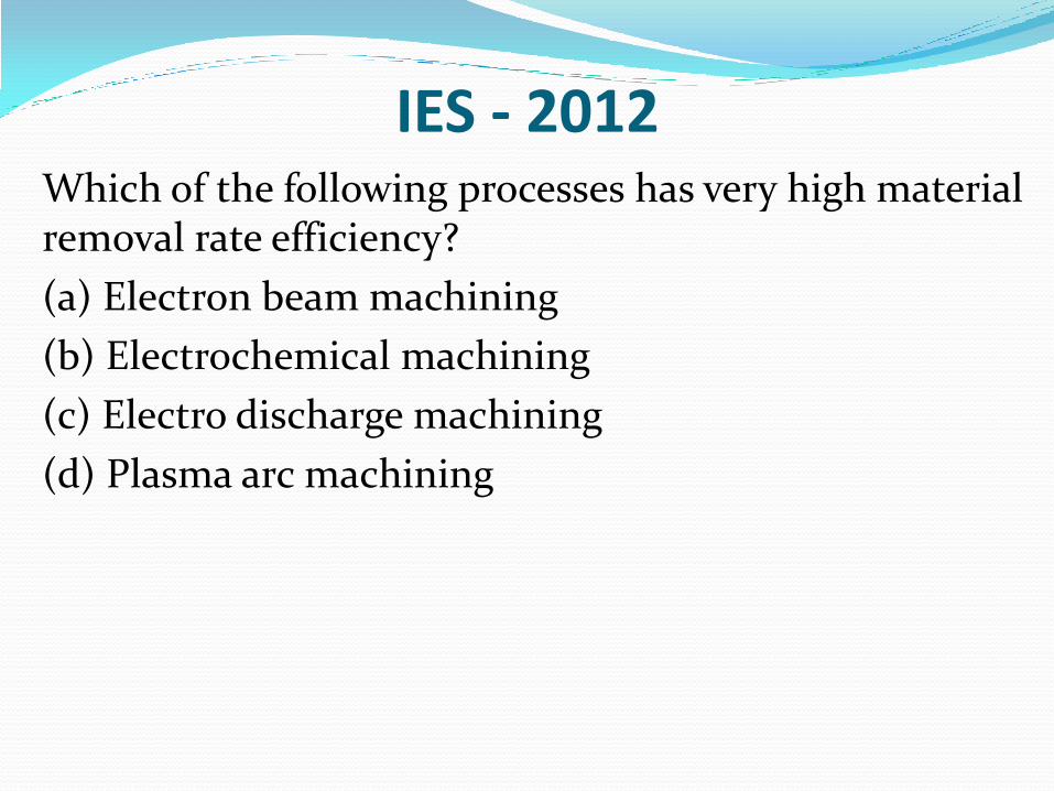
IES - 2012 Which of the following processes has very high material
removal rate efficiency?
(a) Electron beam machining
(b) Electrochemical machining
(c) Electro discharge machining
(d) Plasma arc machining
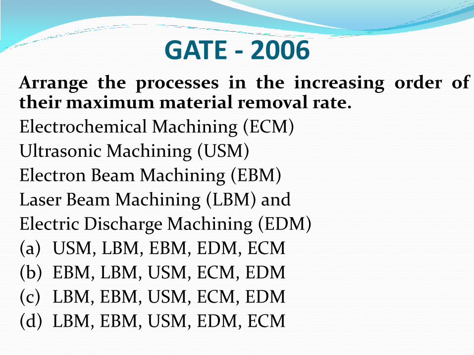
GATE - 2006 Arrange the processes in the increasing order of
their maximum material removal rate.
Electrochemical Machining (ECM)
Ultrasonic Machining (USM)
Electron Beam Machining (EBM)
Laser Beam Machining (LBM) and
Electric Discharge Machining (EDM)
(a) USM, LBM, EBM, EDM, ECM
(b) EBM, LBM, USM, ECM, EDM
(c) LBM, EBM, USM, ECM, EDM
(d) LBM, EBM, USM, EDM, ECM
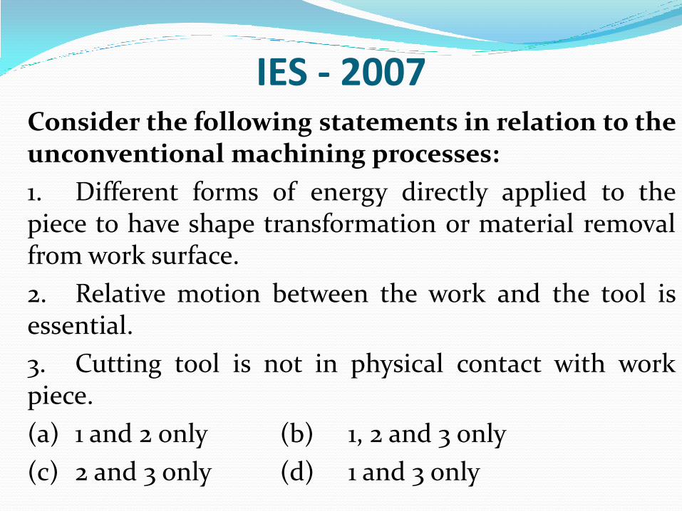
IES - 2007 Consider the following statements in relation to the
unconventional machining processes:
1. Different forms of energy directly applied to the piece to have shape transformation or material removal from work surface.
2. Relative motion between the work and the tool is essential.
3. Cutting tool is not in physical contact with work piece.
(a) 1 and 2 only (b) 1, 2 and 3 only
(c) 2 and 3 only (d) 1 and 3 only
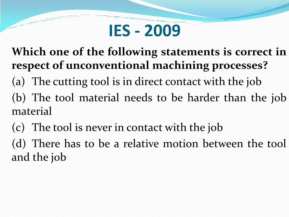
IES - 2009 Which one of the following statements is correct in
respect of unconventional machining processes?
(a) The cutting tool is in direct contact with the job
(b) The tool material needs to be harder than the job material
(c) The tool is never in contact with the job
(d) There has to be a relative motion between the tool and the job
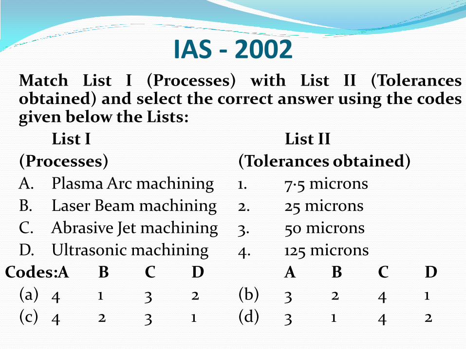
IAS - 2002 Match List I (Processes) with List II (Tolerances
obtained) and select the correct answer using the codes given below the Lists:
List I List II
(Processes) (Tolerances obtained)
A. Plasma Arc machining 1. 7·5 microns
B. Laser Beam machining 2. 25 microns
C. Abrasive Jet machining 3. 50 microns
D. Ultrasonic machining 4. 125 microns
Codes:A B C D A B C D
(a) 4 1 3 2 (b) 3 2 4 1
(c) 4 2 3 1 (d) 3 1 4 2
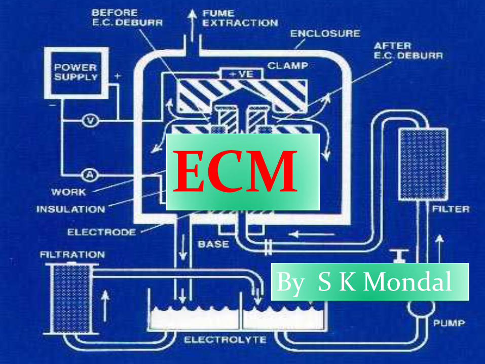
ECM
By S K Mondal
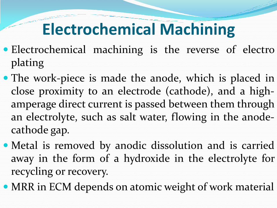
Electrochemical Machining Electrochemical machining is the reverse of electro
plating
The work-piece is made the anode, which is placed in close proximity to an electrode (cathode), and a high-amperage direct current is passed between them through an electrolyte, such as salt water, flowing in the anode-cathode gap.
Metal is removed by anodic dissolution and is carried away in the form of a hydroxide in the electrolyte for recycling or recovery.
MRR in ECM depends on atomic weight of work material
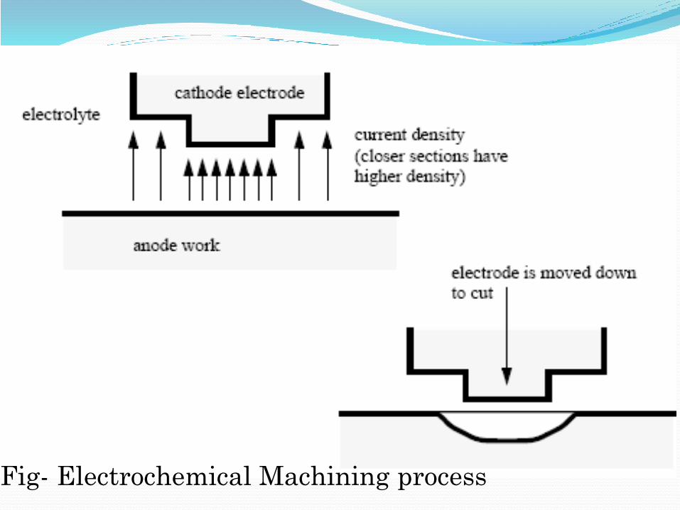
Fig- Electrochemical Machining process
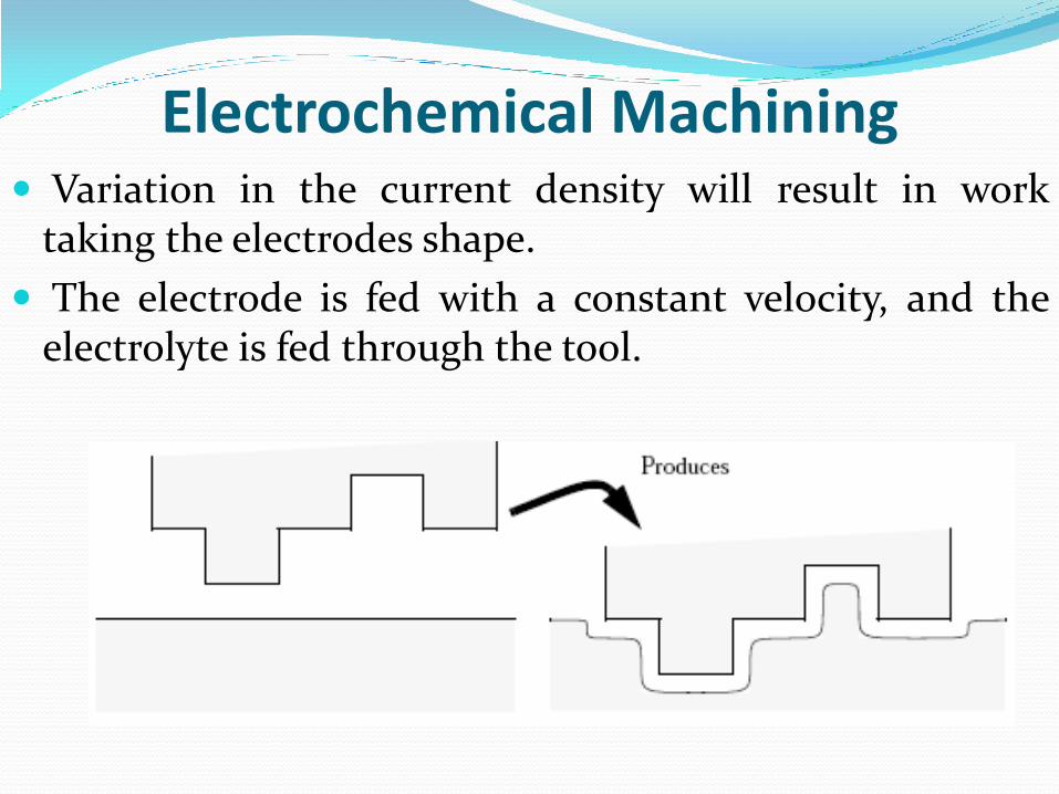
Electrochemical Machining Variation in the current density will result in work
taking the electrodes shape.
The electrode is fed with a constant velocity, and the electrolyte is fed through the tool.
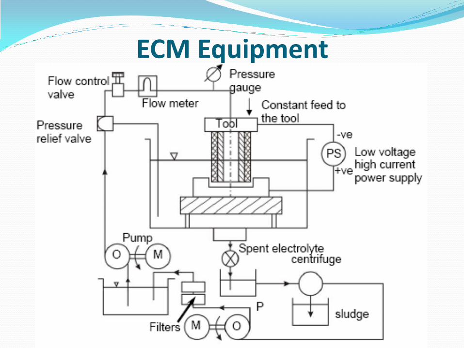
ECM Equipment
ECM Equipment Supply Voltage 2 to 35 V DC and Current 500 to 40,000 A
The tool-to-work gap needs to be maintained at a very small value 0.1 to 0.25 mm. A servo drive is provided on the tool axis for this purpose.
The electrolyte needs to be pumped through this gap at high pressures ranging from 0.70 to 3.00 MPa. This introduces a large amount of load on the machine, because of the large working areas involved. Hence the machine structure will have to be made rigid to a withstand such forces.
ECM Equipment The electrolyte consists of the metal debris removed
from the anode, which will have to be filtered before it is re-pumped into the system.
Also a large amount of heat is generated during the electrolysis, which heats up the electrolyte, and hence it needs to be cooled.
Electrolyte The electrolyte is so chosen that the anode (workpiece)
is dissolved but no deposition takes place on the cathode (tool).
Properties electrolyte should be
1. High electrical conductivity
2. Low viscosity
3. High specific heat
4. Chemical stability
5. Resistance to formation of passivating film on workpiece surface
6. Non-corrosive and non-toxic
7. Inexpensive and readily available
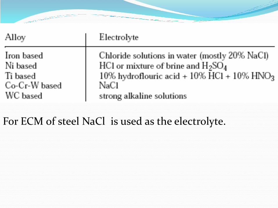
For ECM of steel NaCl is used as the electrolyte.
Tool The properties of tool materials should be:
1. High electrical and thermal comductivity
2. Easy machinability
3. Good shiffness
4. High corrosion resistance
Tool materials: Copper, brass, bronze, Al, Stainless
Steel, Cupro nickel, etc.
Material wear / Tool wear: Infinite
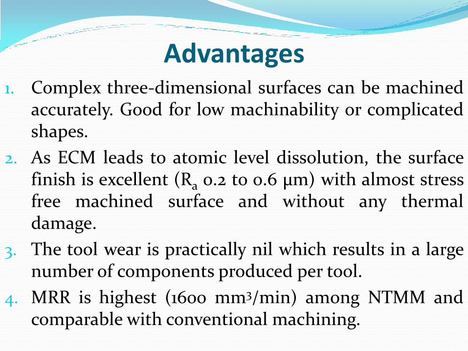
Advantages 1. Complex three-dimensional surfaces can be machined
accurately. Good for low machinability or complicated shapes.
2. As ECM leads to atomic level dissolution, the surface finish is excellent (Ra 0.2 to 0.6 μm) with almost stress free machined surface and without any thermal damage.
3. The tool wear is practically nil which results in a large number of components produced per tool.
4. MRR is highest (1600 mm3/min) among NTMM and comparable with conventional machining.
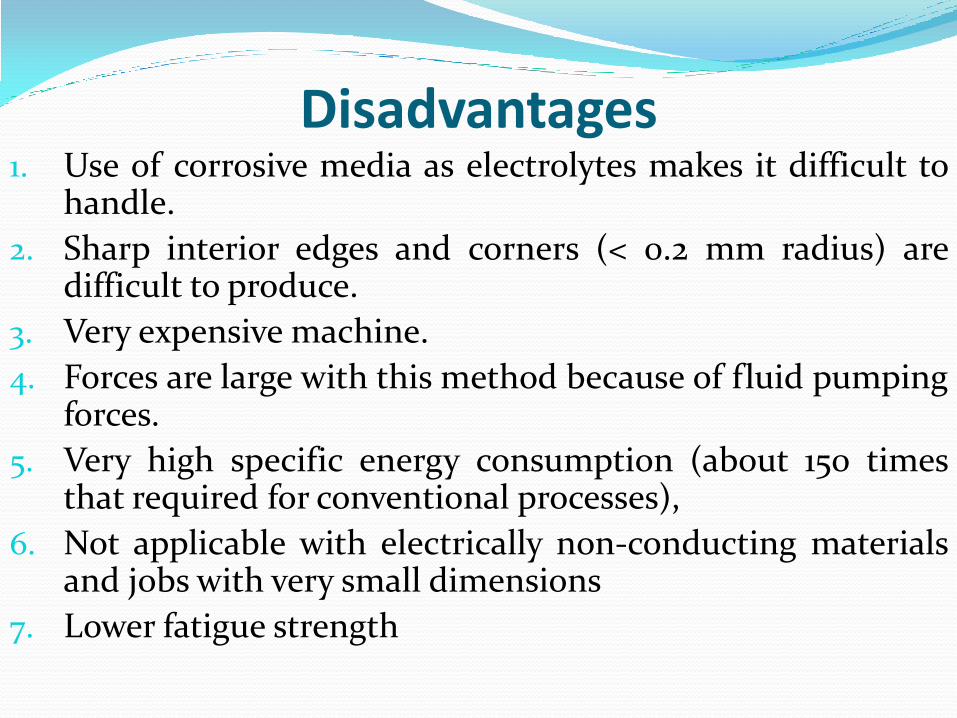
Disadvantages 1. Use of corrosive media as electrolytes makes it difficult to
handle.
2. Sharp interior edges and corners (< 0.2 mm radius) are difficult to produce.
3. Very expensive machine.
4. Forces are large with this method because of fluid pumping forces.
5. Very high specific energy consumption (about 150 times that required for conventional processes),
6. Not applicable with electrically non-conducting materials and jobs with very small dimensions
7. Lower fatigue strength
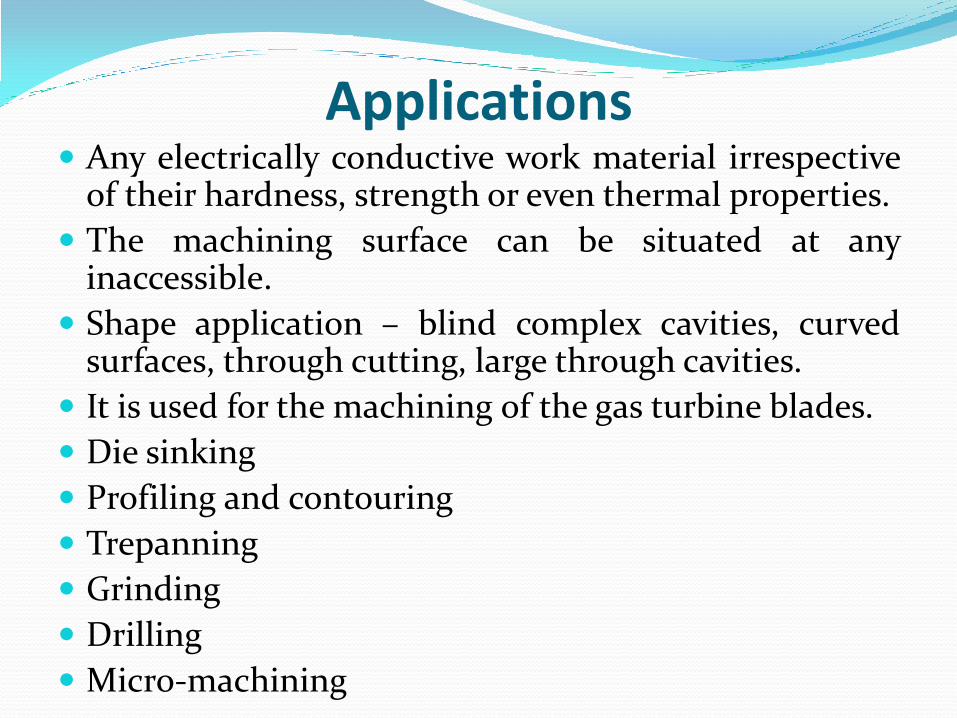
Applications Any electrically conductive work material irrespective
of their hardness, strength or even thermal properties.
The machining surface can be situated at any inaccessible.
Shape application – blind complex cavities, curved surfaces, through cutting, large through cavities.
It is used for the machining of the gas turbine blades.
Die sinking
Profiling and contouring
Trepanning
Grinding
Drilling
Micro-machining
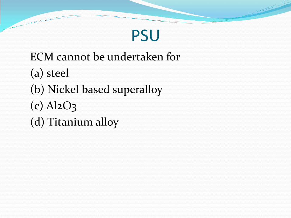
PSU ECM cannot be undertaken for
(a) steel
(b) Nickel based superalloy
(c) Al2O3
(d) Titanium alloy
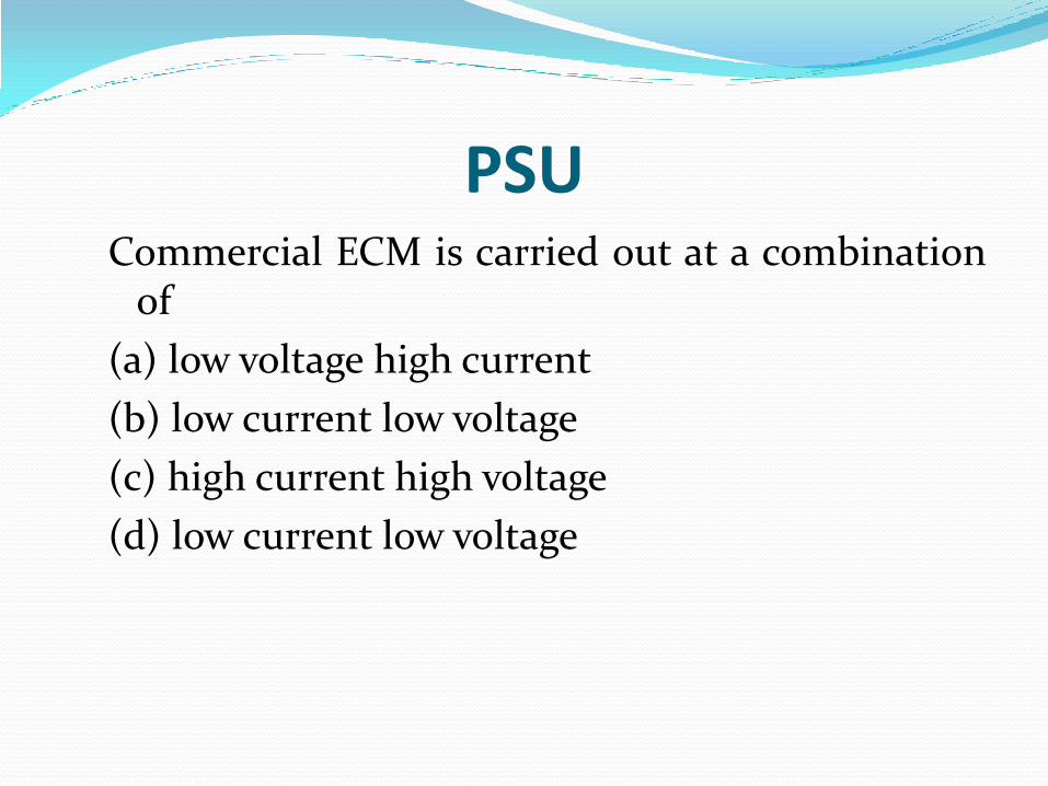
PSU Commercial ECM is carried out at a combination
of
(a) low voltage high current
(b) low current low voltage
(c) high current high voltage
(d) low current low voltage
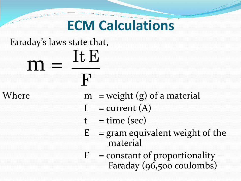
ECM Calculations Faraday’s laws state that,
m =
Where m = weight (g) of a material
I = current (A)
t = time (sec)
E = gram equivalent weight of the material
F = constant of proportionality – Faraday (96,500 coulombs)
It E
F
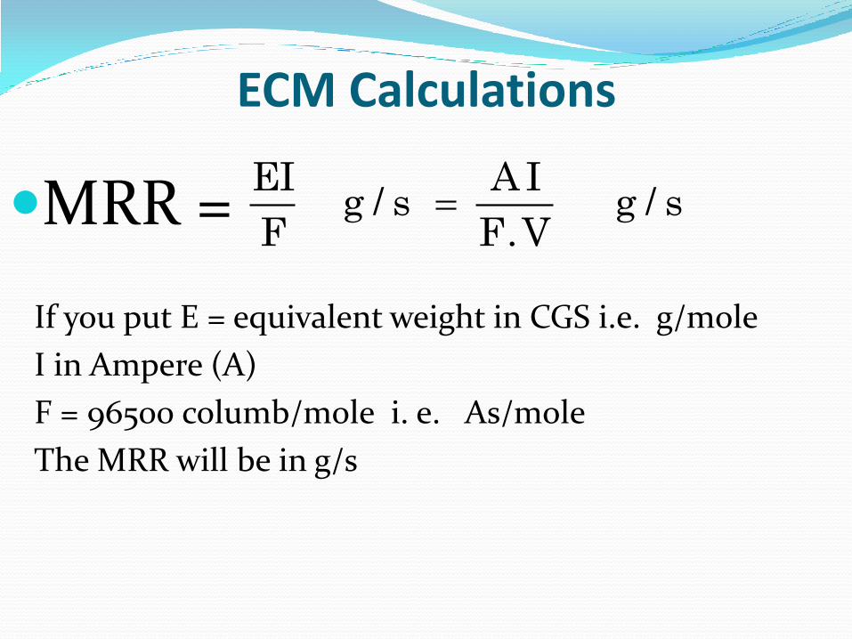
ECM Calculations
MRR =
If you put E = equivalent weight in CGS i.e. g/mole
I in Ampere (A)
F = 96500 columb/mole i. e. As/mole
The MRR will be in g/s
EI A I
g / s g / sF F.V
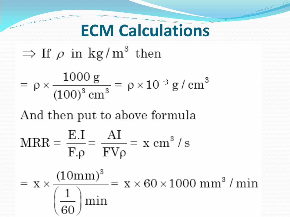
ECM Calculations
-3
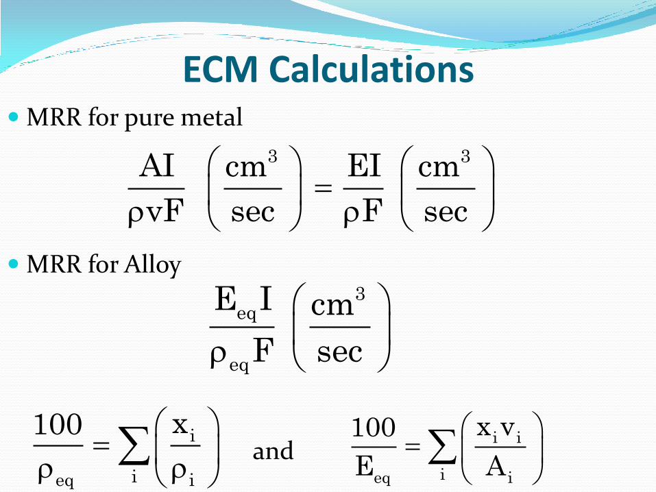
ECM Calculations MRR for pure metal
MRR for Alloy
3 3AI cm EI cm
vF sec F sec
3eq
eq
E I cm
F sec
i
ieq i
x100
i i
ieq i
x v100
E Aand
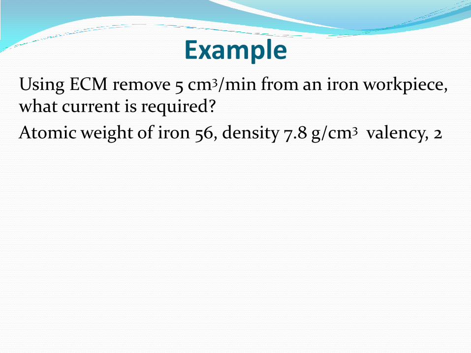
Example Using ECM remove 5 cm3/min from an iron workpiece,
what current is required?
Atomic weight of iron 56, density 7.8 g/cm3 valency, 2
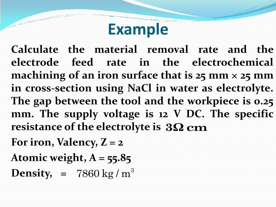
Example Calculate the material removal rate and the
electrode feed rate in the electrochemical machining of an iron surface that is 25 mm × 25 mm in cross-section using NaCl in water as electrolyte. The gap between the tool and the workpiece is 0.25 mm. The supply voltage is 12 V DC. The specific resistance of the electrolyte is
For iron, Valency, Z = 2
Atomic weight, A = 55.85
Density, =
3Ωcm
37860 kg / m
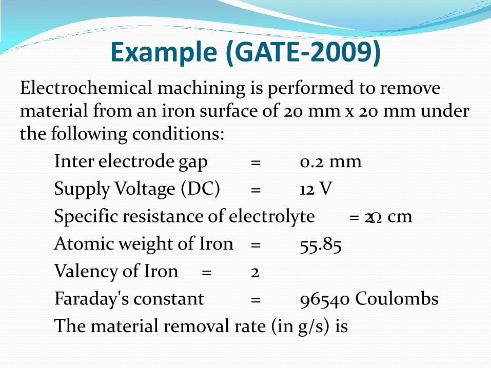
Example (GATE-2009) Electrochemical machining is performed to remove
material from an iron surface of 20 mm x 20 mm under the following conditions:
Inter electrode gap = 0.2 mm
Supply Voltage (DC) = 12 V
Specific resistance of electrolyte = 2 cm
Atomic weight of Iron = 55.85
Valency of Iron = 2
Faraday's constant = 96540 Coulombs
The material removal rate (in g/s) is
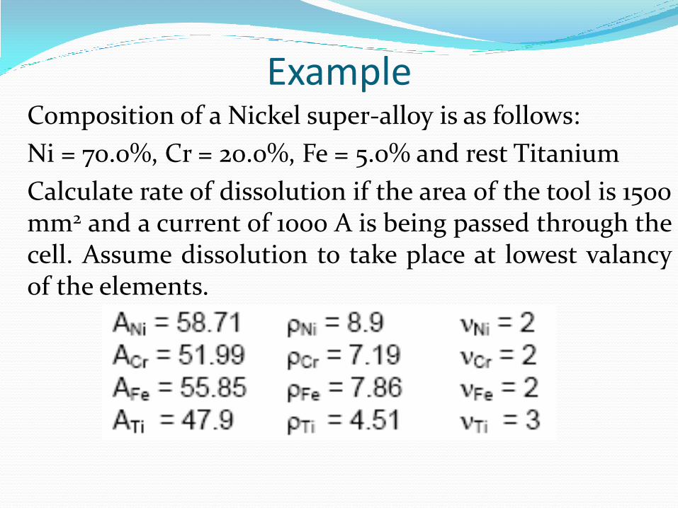
Example Composition of a Nickel super-alloy is as follows:
Ni = 70.0%, Cr = 20.0%, Fe = 5.0% and rest Titanium
Calculate rate of dissolution if the area of the tool is 1500 mm2 and a current of 1000 A is being passed through the cell. Assume dissolution to take place at lowest valancy of the elements.
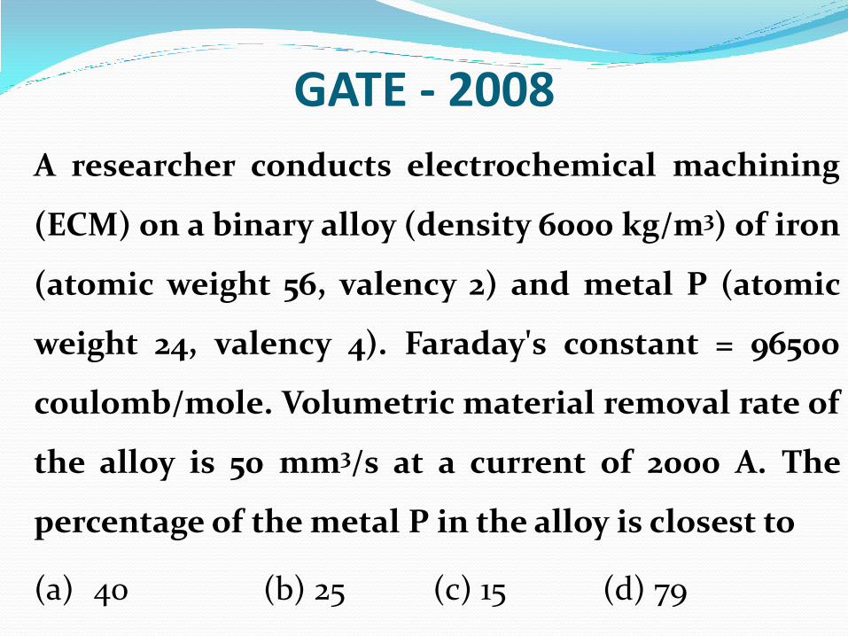
GATE - 2008
A researcher conducts electrochemical machining
(ECM) on a binary alloy (density 6000 kg/m3) of iron
(atomic weight 56, valency 2) and metal P (atomic
weight 24, valency 4). Faraday's constant = 96500
coulomb/mole. Volumetric material removal rate of
the alloy is 50 mm3/s at a current of 2000 A. The
percentage of the metal P in the alloy is closest to
(a) 40 (b) 25 (c) 15 (d) 79
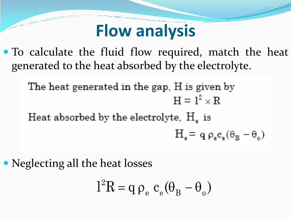
Flow analysis To calculate the fluid flow required, match the heat
generated to the heat absorbed by the electrolyte.
Neglecting all the heat losses
2
e e B ol R q c ( )
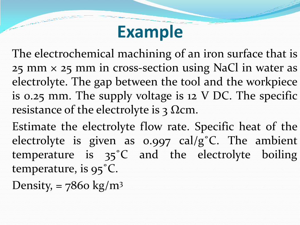
Example The electrochemical machining of an iron surface that is
25 mm × 25 mm in cross-section using NaCl in water as electrolyte. The gap between the tool and the workpiece is 0.25 mm. The supply voltage is 12 V DC. The specific resistance of the electrolyte is 3 Ωcm.
Estimate the electrolyte flow rate. Specific heat of the electrolyte is given as 0.997 cal/g˚C. The ambient temperature is 35˚C and the electrolyte boiling temperature, is 95˚C.
Density, = 7860 kg/m3
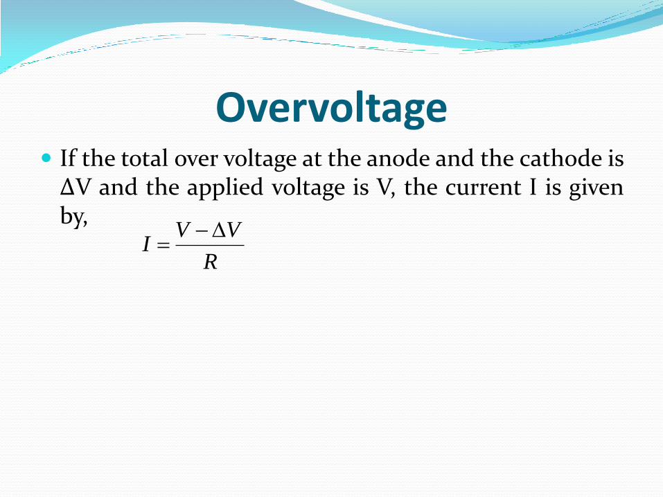
Overvoltage If the total over voltage at the anode and the cathode is ΔV and the applied voltage is V, the current I is given by,
R
VVI
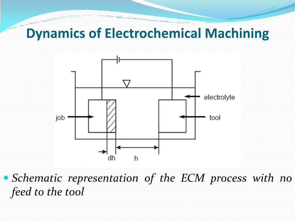
Dynamics of Electrochemical Machining
Schematic representation of the ECM process with no feed to the tool
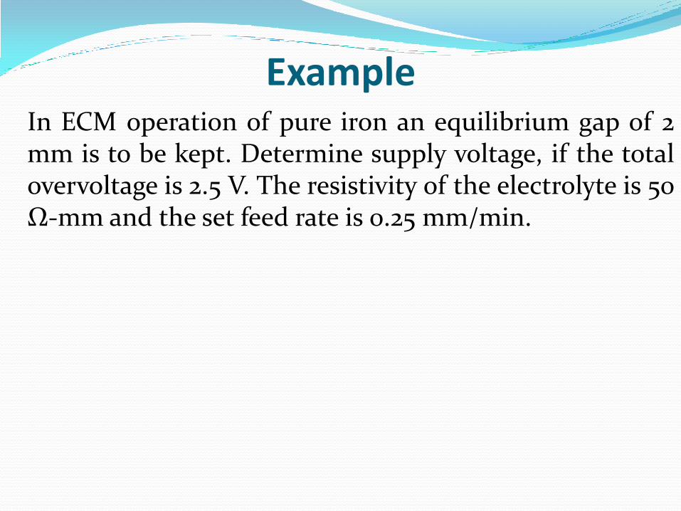
Example In ECM operation of pure iron an equilibrium gap of 2
mm is to be kept. Determine supply voltage, if the total overvoltage is 2.5 V. The resistivity of the electrolyte is 50 Ω-mm and the set feed rate is 0.25 mm/min.
Electrochemical Grinding (ECG) In ECG, the tool electrode is a rotating, metal bonded,
diamond grit grinding wheel.
As the electric current flows between the workpiece and the wheel, through the electrolyte, the surface metal is changed to a metal oxide, which is ground away by the abrasives. As the oxide film is removed, new surface metal is oxidized and removed.
ECG is a low-voltage high-current electrical process.
The purpose of the abrasive is to increase the efficiency of the ECG process and permit the continuance of the process.
The abrasive particles are always nonconductive material such as aluminum oxide, diamond, or borazon (CBN). Thus they act as an insulating spacer maintaining a separation of from 0.012 to 0.050 mm between the electrodes.
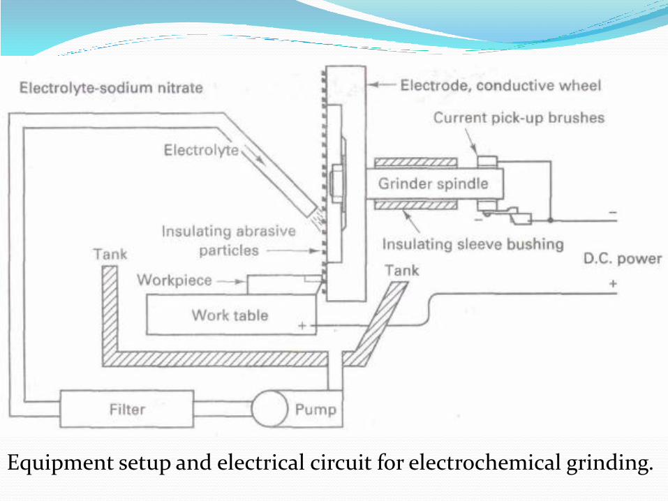
Equipment setup and electrical circuit for electrochemical grinding.
Electrochemical Grinding (ECG) The process is used for shaping and sharpening
carbide cutting tools, which cause high wear rates on expensive diamond wheels in normal grinding. Electrochemical grinding greatly reduces this wheel wear.
Fragile parts (honeycomb structures), surgical needles, and tips of assembled turbine blades have been ECG-processed successfully.
The lack of heat damage, burrs, and residual stresses is very beneficial, particularly when coupled with MRRs that are competitive with conventional grinding but with far less wheel wear.
Other Electrochemical processes
Electrochemical polishing
Electrochemical hole-drilling
Electrochemical Deburring
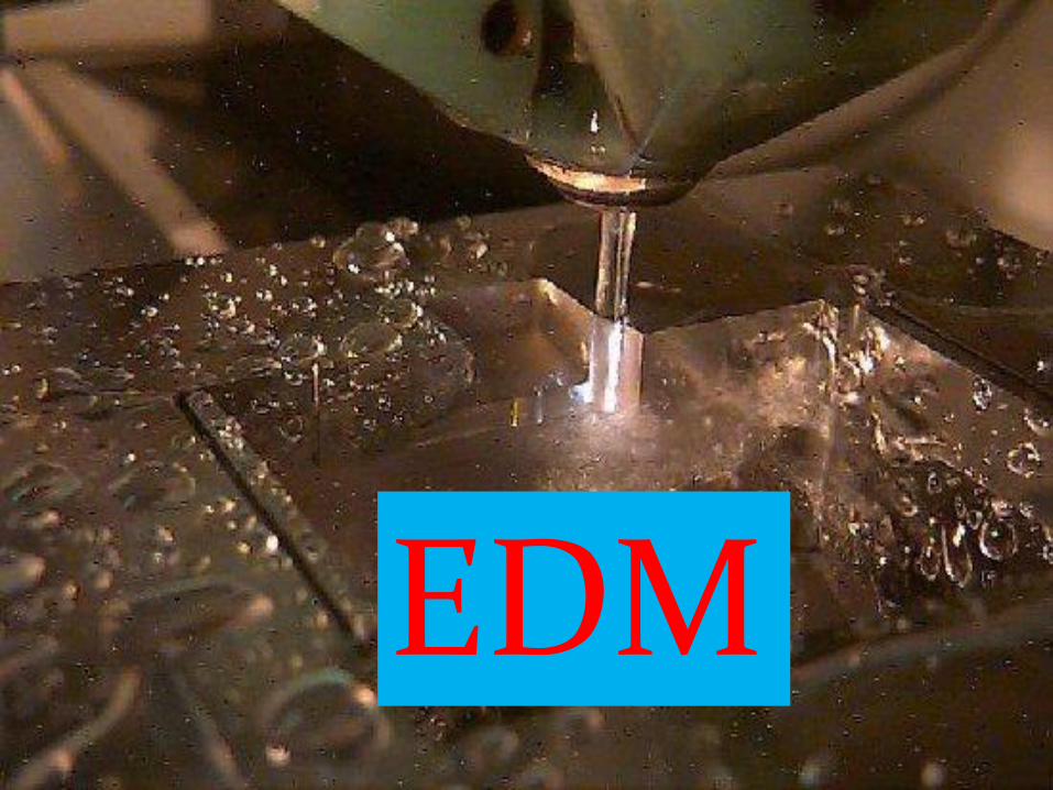
EDM
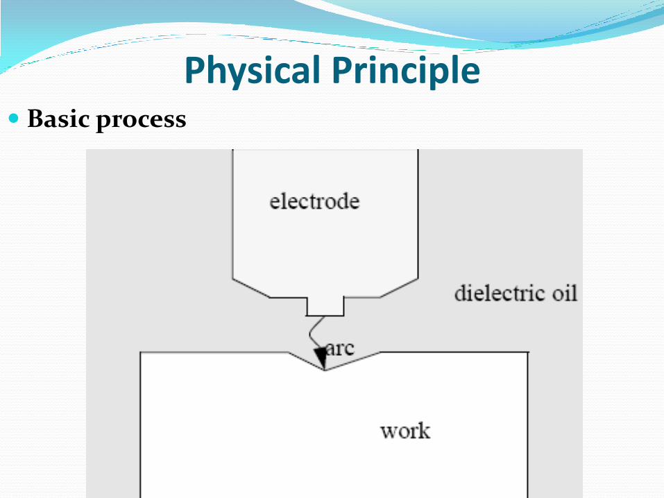
Physical Principle Basic process
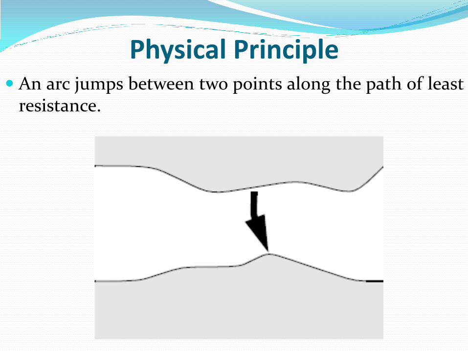
Physical Principle An arc jumps between two points along the path of least
resistance.
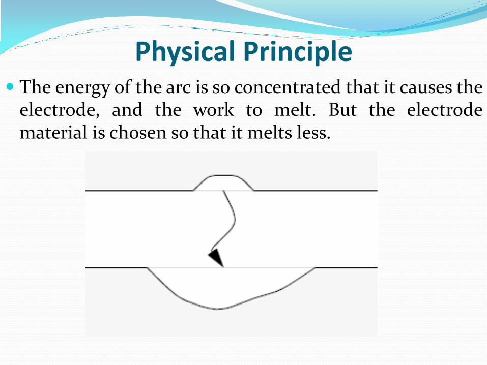
Physical Principle The energy of the arc is so concentrated that it causes the
electrode, and the work to melt. But the electrode material is chosen so that it melts less.
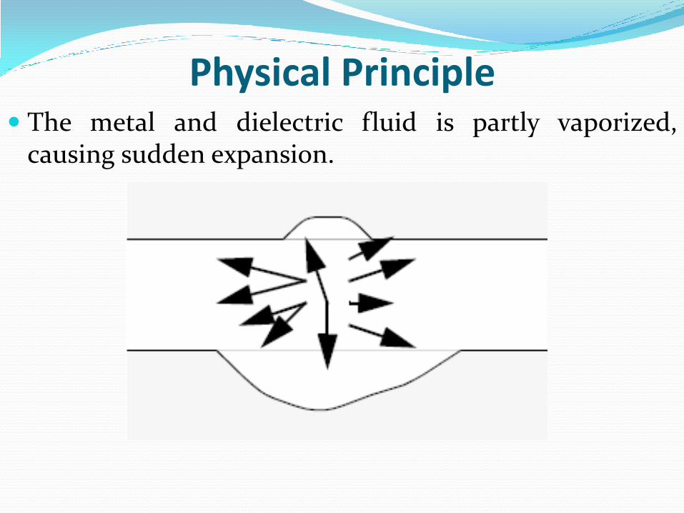
Physical Principle The metal and dielectric fluid is partly vaporized,
causing sudden expansion.
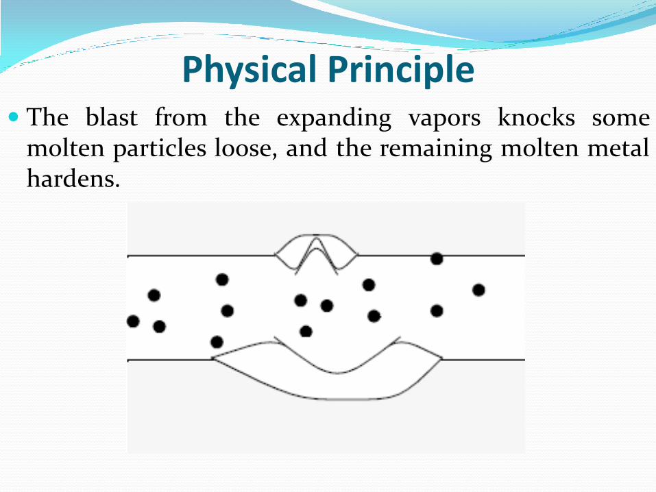
Physical Principle The blast from the expanding vapors knocks some
molten particles loose, and the remaining molten metal hardens.


Characteristics of EDM Mechanics of material removal - melting and
evaporation aided by cavitation.
The process is based on melting temperature, not hardness, so some very hard materials can be machined this way.
The arc that jumps heats the metal, and about 1 to 10% of the molten metal goes into the fluid. The melted metal then recast layer is about 1 to 30 μm thick, and is generally hard and rough.
The electrode workpiece gap is in the range of 10 μm to 100 μm.
Characteristics of EDM Uses Voltage of 60 to 300 V to give a transient arc lasting
from 0.1 μ s to 8 ms.
Typical cycle time is 20 ms or less, up to millions of cycles may be required for completion of the part.
Rotating the wire in an orbital direction will,
- Increase accuracy in form and surface finish
- Decrease electrode wear
Surface finish obtained 0.25 μm
EDM Tool Prime requirements EDM tool Material
1. It should be electrically conductive.
2. It should have good machinability, thus allowing easy manufacture of complex shapes.
3. It should have low erosion rate or good work to tool wear ratio.
4. It should have low electrical resistance.
5. It should have high melting point.
6. It should have high electron emission.
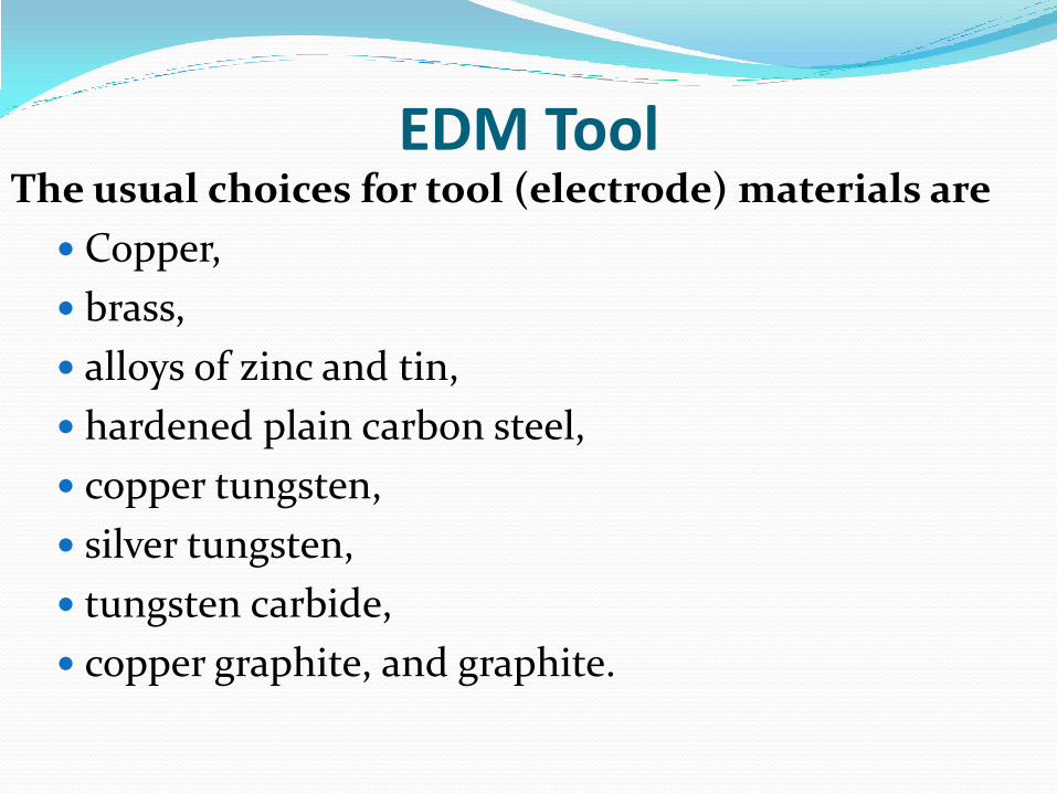
EDM Tool The usual choices for tool (electrode) materials are
Copper,
brass,
alloys of zinc and tin,
hardened plain carbon steel,
copper tungsten,
silver tungsten,
tungsten carbide,
copper graphite, and graphite.
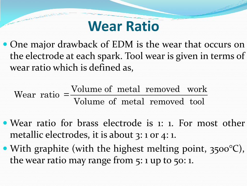
Wear Ratio One major drawback of EDM is the wear that occurs on
the electrode at each spark. Tool wear is given in terms of wear ratio which is defined as,
Wear ratio for brass electrode is 1: 1. For most other metallic electrodes, it is about 3: 1 or 4: 1.
With graphite (with the highest melting point, 3500°C), the wear ratio may range from 5: 1 up to 50: 1.
Volume of metal removed workWear ratio =
Volume of metal removed tool
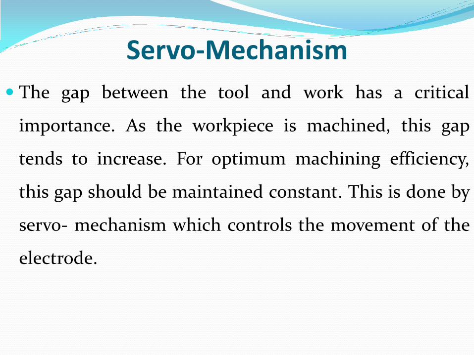
Servo-Mechanism
The gap between the tool and work has a critical
importance. As the workpiece is machined, this gap
tends to increase. For optimum machining efficiency,
this gap should be maintained constant. This is done by
servo- mechanism which controls the movement of the
electrode.
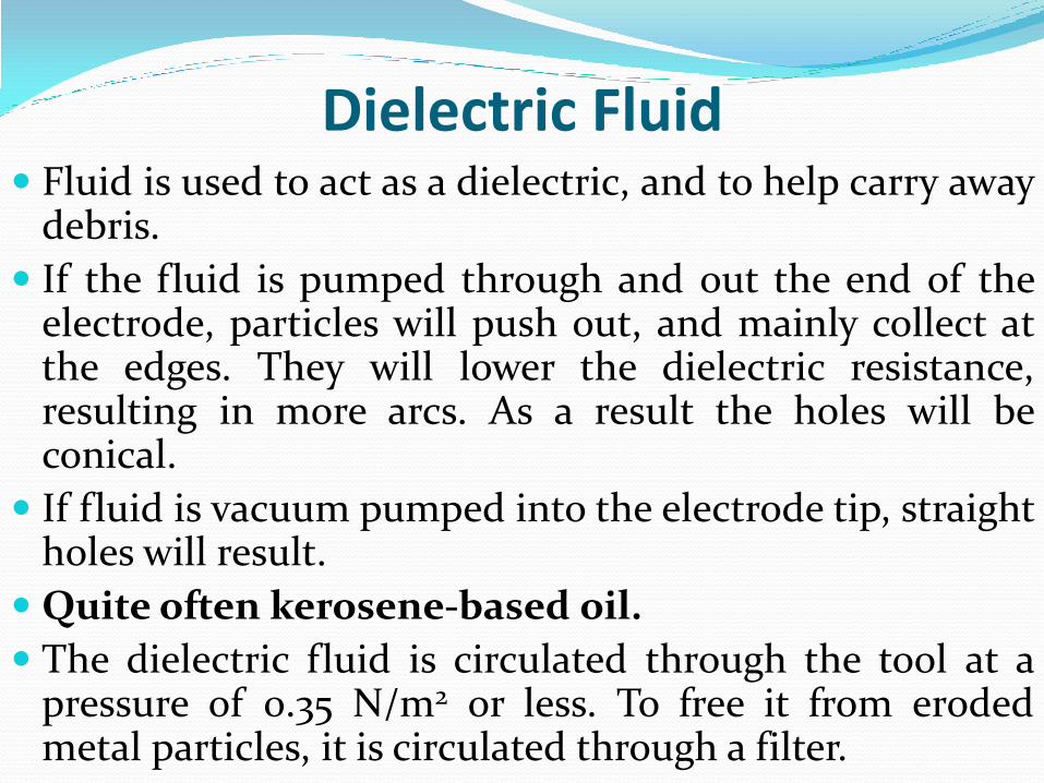
Dielectric Fluid Fluid is used to act as a dielectric, and to help carry away
debris.
If the fluid is pumped through and out the end of the electrode, particles will push out, and mainly collect at the edges. They will lower the dielectric resistance, resulting in more arcs. As a result the holes will be conical.
If fluid is vacuum pumped into the electrode tip, straight holes will result.
Quite often kerosene-based oil.
The dielectric fluid is circulated through the tool at a pressure of 0.35 N/m2 or less. To free it from eroded metal particles, it is circulated through a filter.
IES 2011 Conventional Discuss the effects of insufficient dielectric and
electrolyte circulation in the inter-electrode gap on the
Electric Discharge machining and Electro Chemical
Machining process respectively. [5 Marks]
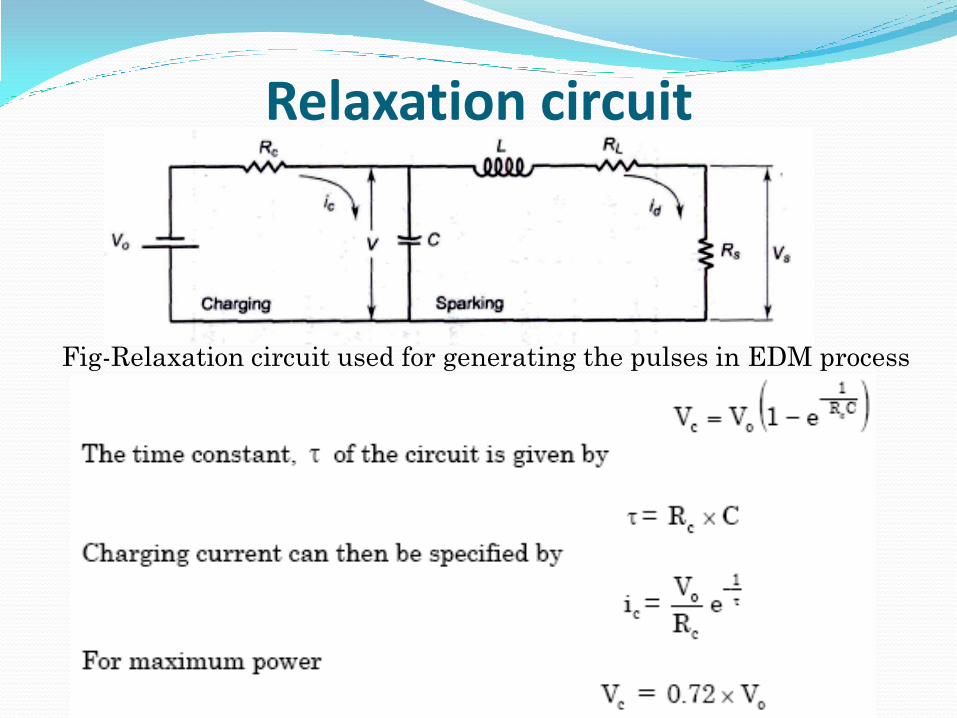
Relaxation circuit
Fig-Relaxation circuit used for generating the pulses in EDM process
Advantages 1. Hardness, toughness or brittleness of the material poses no
problems. Due to this EDM can be used for machining materials that are too hard or brittle to be machined by conventional methods.
2. The method does not leave any chips or burrs on the work piece.
3. Cutting forces are virtually zero, so very delicate and fine work can be done.
4. The process dimension repeatability and surface finish obtained in finishing are extremely good.
5. The characteristic surface obtained, which is made up of craters, helps in better oil retention. This improves die life.
6. Because the forces between the tool and the workpiece and virtually zero, very delicate work can be done.
Disadvantages 1. Only electrically conductive materials can be machined
by EDM. Thus non - metallic, such as plastics, ceramics or glass, cannot be machined by EDM.
2. Electrode wear and over-cut are serious problems.
3. A re-hardened, highly stressed zone is produced on the work surface by the heat generated during machining. This brittle layer can cause serious problems when the part is put into service.
4. Perfectly square corners cannot be made by EDM.
5. High specific energy consumption (about 50 times that in conventional machining)
6. MRR is quite low
Applications
EDM can be used for machining any material that is
electrically conductive, thus including metals, alloys and
most carbides.
EDM is widely used for machining burr free intricate
shapes, narrow slots and blind cavities etc., for example,
sinking of dies for moulding, die casting, plastic
moulding, wire drawing, compacting, cold heading,
forging, extrusion and press tools.
Applications
EDM is particularly useful when dealing with internal
cuts that are hard to get tools into. Machining tends to
work best with external cuts.
Almost any geometry (negative of tool geometry) can be
generated on a workpiece if a suitable tool can be
fabricated (the use of punch as a tool to machine its own
mating die is commonly employed in EDM method).
Applications The method is also employed for blanking parts from sheets,
cutting off rods of materials, flat or form grinding and
sharpening of tools, cutters and broaches.
In EDM method, small holes, about 0.13 mm, in
diameter and as deep as 20mm diameters can be drilled
with virtually no bending or drifting of hole. Due to this,
EDM is particularly useful for machining of small holes,
orifices or slots in diesel-fuel injection nozzles, or in aircraft
engines, air brake valves and so on.
IES 2009 Conventional i. What is the principle of metal removal in EDM
process?
ii. Describe the process with the help of sketch.
iii. List advantages and limitations of the system.
[ 15 marks]
Wire EDM Wire EDM is a special form of EDM wherein the
electrode is a continuously moving conductive wire.
A thin wire of brass, tungsten, or copper is used as an
electrode.
The electrode wire is typically made with a 0.05 to 0.25-
mm diameter, which is wire electrode wound between
the two spools.
Deionized water is used as the dielectric.

Wire EDM - 1

Wire EDM - 2
Wire EDM
This process is much faster than electrode EDM.
This process is widely used for the manufacture of
punches, dies, and stripper plates, with modern
machines capable of cutting die relief, intricate
openings, tight radius contours, and corners routinely.
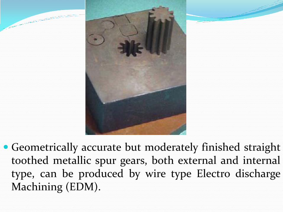
Geometrically accurate but moderately finished straight toothed metallic spur gears, both external and internal type, can be produced by wire type Electro discharge Machining (EDM).
Electric Discharge Grinding (EDG) EDG is similar to EDM except that the electrode is a
rotating wheel (usually graphite).
Positively charged work pieces are immersed in or flooded by a dielectric fluid and fed past the negatively charged wheel by servo-controlled machine table.
Metal is removed by intermittent high frequency electrical discharges passing through the gap between wheel and workpiece.
Each spark discharge melts or vaporizes a small amount of metal from the workpiece surface, producing a small crate at the discharge sit, as in EDM.
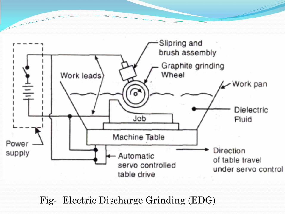
Fig- Electric Discharge Grinding (EDG)
Electric Discharge Grinding (EDG) The spark gap is normally held at 0.013 to 0.076 mm
The graphite wheel is rotated at 0.5 to 3 m/s
The method can be used for
1. External cylindrical grinding, internal grinding and surface grinding.
2. Grinding carbide and steel at the same time without wheel loading.
3. Grinding thin sections where abrasive wheel pressures might cause distortion.
4. Grinding brittle materials or fragile parts where abrasive materials might cause fracturing.
IES - 2012 Statement (I): In Electro Discharge Machining (EDM)
process, tool is made cathode and work piece anode
Statement (II): In this process if both electrodes are made of same material, greatest erosion takes place upon anode
(a) Both Statement (I) and Statement (II) are individually true and Statement (II) is the correct explanation of Statement (I)
(b) Both Statement (I) and Statement (II) are individually true but Statement (II) is not the correct explanation of Statement (I)
(c) Statement (I) is true but Statement (II) is false
(d) Statement (I) is false but Statement (II) is true
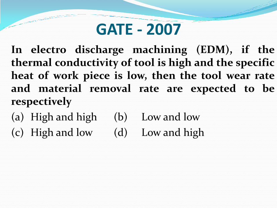
GATE - 2007 In electro discharge machining (EDM), if the
thermal conductivity of tool is high and the specific heat of work piece is low, then the tool wear rate and material removal rate are expected to be respectively
(a) High and high (b) Low and low
(c) High and low (d) Low and high
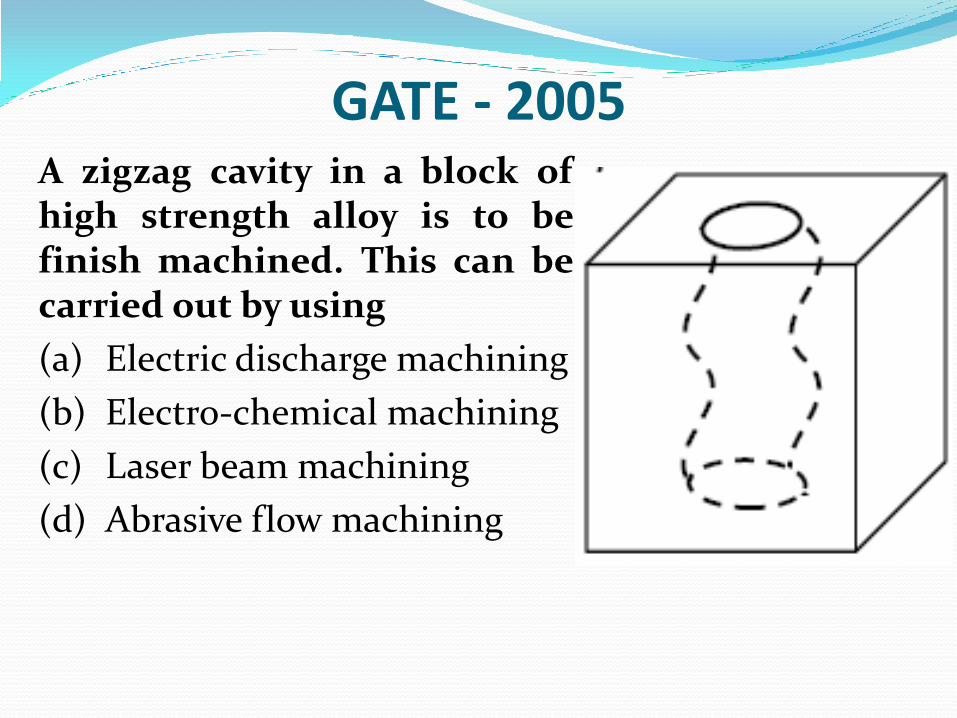
GATE - 2005 A zigzag cavity in a block of
high strength alloy is to be finish machined. This can be carried out by using
(a) Electric discharge machining
(b) Electro-chemical machining
(c) Laser beam machining
(d) Abrasive flow machining
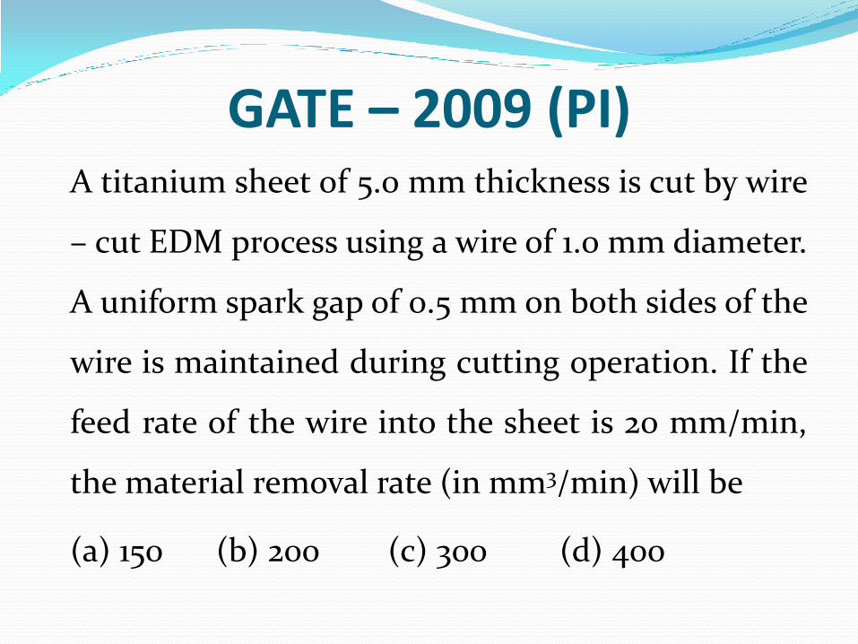
GATE – 2009 (PI) A titanium sheet of 5.0 mm thickness is cut by wire
– cut EDM process using a wire of 1.0 mm diameter.
A uniform spark gap of 0.5 mm on both sides of the
wire is maintained during cutting operation. If the
feed rate of the wire into the sheet is 20 mm/min,
the material removal rate (in mm3/min) will be
(a) 150 (b) 200 (c) 300 (d) 400
Ultrasonic Machining
By S K Mondal
Ultrasonic Machining
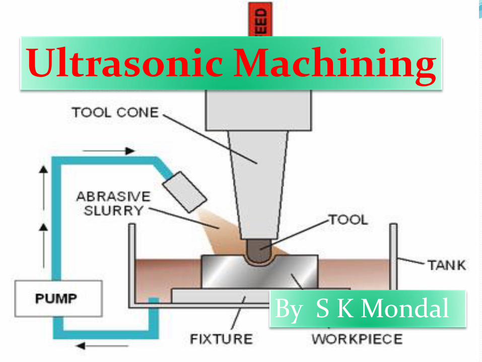
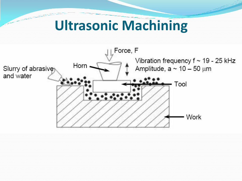
Ultrasonic Machining In ultrasonic machining, a tool of desired shape vibrates at an
ultrasonic frequency (19 ~ 25 kHz) with an amplitude of around 15 – 50 μm over the workpiece.
Generally the tool is pressed downward with a feed force, F. Between the tool and workpiece, the machining zone is flooded with hard abrasive particles generally in the form of water based slurry.
As the tool vibrates over the workpiece, the abrasive particles act as the indenters and indent both the work material and the tool. The abrasive particles, as they indent, the work material, would remove the same, particularly if the work material is brittle, due to crack initiation, propagation and brittle fracture of the material.
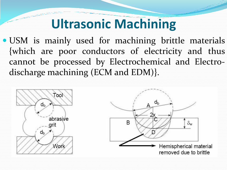
Ultrasonic Machining USM is mainly used for machining brittle materials
{which are poor conductors of electricity and thus cannot be processed by Electrochemical and Electro-discharge machining (ECM and EDM)}.
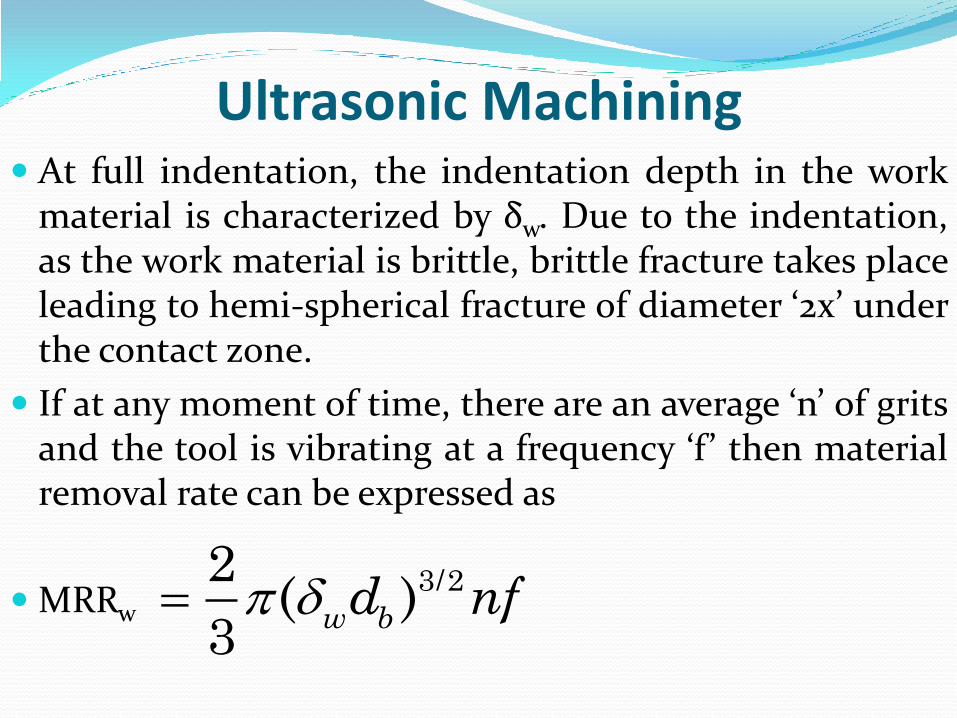
Ultrasonic Machining At full indentation, the indentation depth in the work
material is characterized by δw. Due to the indentation, as the work material is brittle, brittle fracture takes place leading to hemi-spherical fracture of diameter ‘2x’ under the contact zone.
If at any moment of time, there are an average ‘n’ of grits and the tool is vibrating at a frequency ‘f ’ then material removal rate can be expressed as
MRRw
3/22( )
3w bd nf
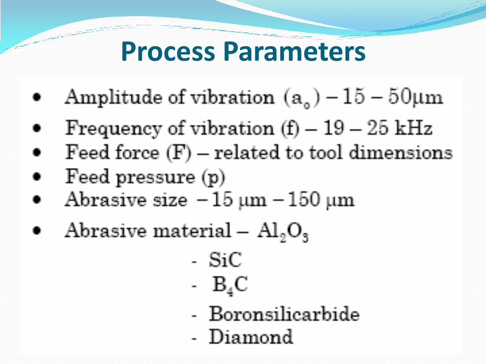
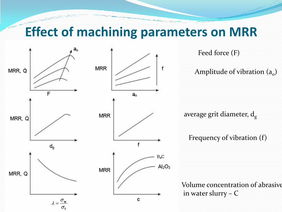
Process Parameters
Effect of machining parameters on MRR
Amplitude of vibration (ao)
Frequency of vibration (f)
Feed force (F)
Volume concentration of abrasive in water slurry – C
average grit diameter, dg
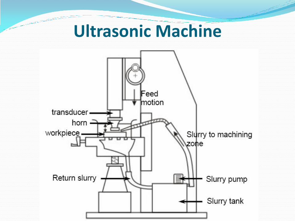
Ultrasonic Machine
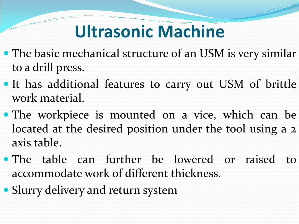
Ultrasonic Machine The basic mechanical structure of an USM is very similar
to a drill press.
It has additional features to carry out USM of brittle work material.
The workpiece is mounted on a vice, which can be located at the desired position under the tool using a 2 axis table.
The table can further be lowered or raised to accommodate work of different thickness.
Slurry delivery and return system
Ultrasonic Machine Feed mechanism to provide a downward feed force on
the tool during machining
The transducer, which generates the ultrasonic vibration
The horn or concentrator, which mechanically amplifies the vibration to the required amplitude of 15 – 50 μm and accommodates the tool at its tip.
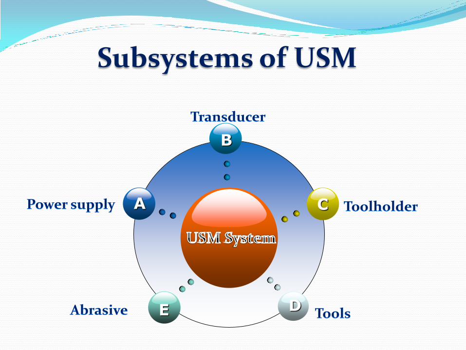
Subsystems of USM
B
E
C
D
A
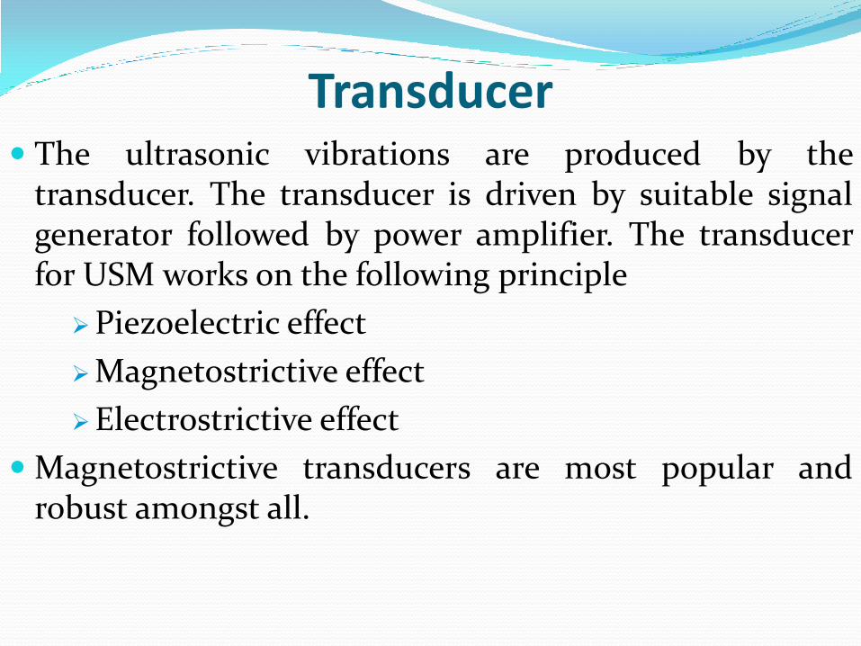
Transducer The ultrasonic vibrations are produced by the
transducer. The transducer is driven by suitable signal generator followed by power amplifier. The transducer for USM works on the following principle
Piezoelectric effect
Magnetostrictive effect
Electrostrictive effect
Magnetostrictive transducers are most popular and robust amongst all.
GATE -2010 (PI) Ultrasonic machines, used in material removal processes,
require ultrasonic transducers. The transducers works on
different working principles. One of the working principles
of such ultrasonic transducers is based on
(a) eddy current effect (b) Seebeck effect
(c) piezo-resistive effect (d) piezo-electric effect
Tool holder or Horn
Its function is to increase the tool vibration amplitude
and to match the vibrator to the acoustic load.
It must be constructed of a material with good acoustic
properties and be highly resistant to fatigue cracking.
Monel and titanium have good acoustic properties and
are often used together with stainless steel, which is
cheaper.
Tool
Tools should be constructed from relatively ductile
materials.
The harder the tool material, the faster its wear rate will
be.
Limitations Low MRR
Rather high tool wear
Low depth of hole
Applications Used for machining hard and brittle metallic alloys,
semiconductors, glass, ceramics, carbides etc.
Used for machining round, square, irregular shaped holes and surface impressions.
Machining, wire drawing, punching or small blanking dies.
Note The following material is generally machined by USM
(i) Glass
(ii) Silicon
(iii) Germanium
Tool in USM is generally made of Steel
IES 2011 USM has good machining performance for :
(a) Al
(b) Steel
(c) Super alloys
(d) Refractory material
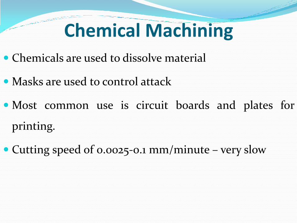
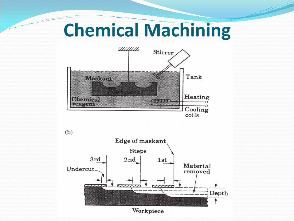
Chemical Machining Chemicals are used to dissolve material
Masks are used to control attack
Most common use is circuit boards and plates for
printing.
Cutting speed of 0.0025-0.1 mm/minute – very slow
Chemical Machining
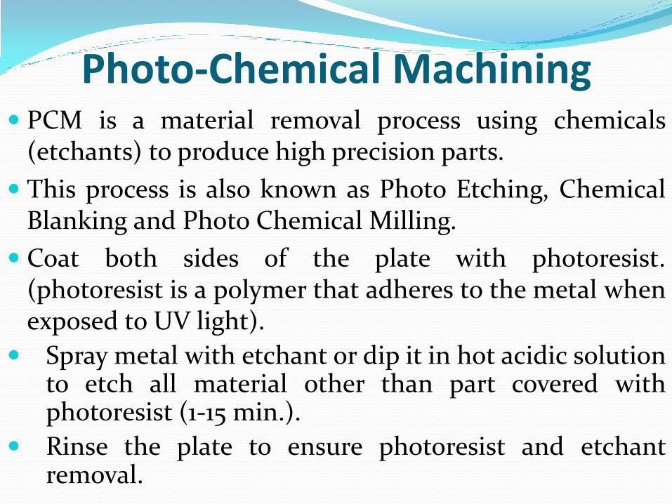
Photo-Chemical Machining PCM is a material removal process using chemicals
(etchants) to produce high precision parts.
This process is also known as Photo Etching, Chemical Blanking and Photo Chemical Milling.
Coat both sides of the plate with photoresist. (photoresist is a polymer that adheres to the metal when exposed to UV light).
Spray metal with etchant or dip it in hot acidic solution to etch all material other than part covered with photoresist (1-15 min.).
Rinse the plate to ensure photoresist and etchant removal.
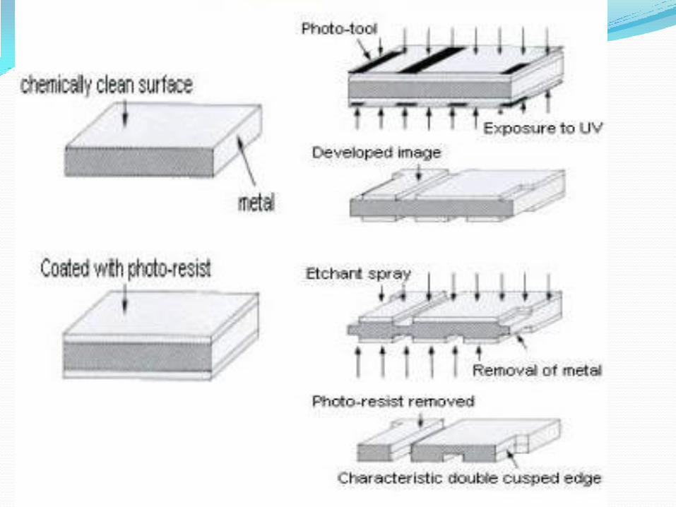
Photo-Chemical Machining
142
Laser Beam Machining
144
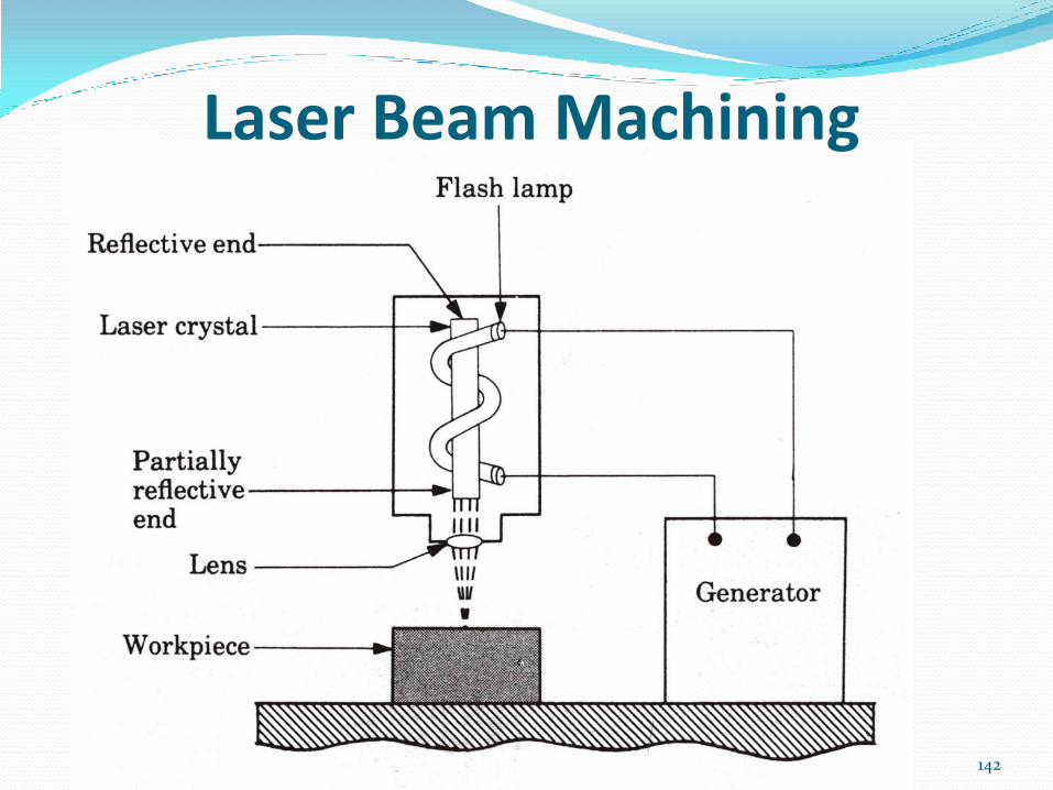
Laser Beam Machining Direct laser beam against surface of workpiece, as in
laser welding
Successive pulses from laser gun vaporize tiny bits of
workpiece
Location of laser beam controlled by computer
Workpiece need not be conductive
Cuts are tapered
Gotta trap overshoot from laser beam
145
Laser Beam Machining Produces large remelt zone
Can produce holes as small as 0.0005 mm diameter
Can produce deep holes
Used to produce cooling holes in blades/vanes for jet
engines
146
Electron Beam Machining Workpiece placed in vacuum chamber
High-voltage electron beam directed toward
workpiece
Energy of electron beam melts/ vaporizes selected
region of workpiece
Electron beam moved by deflection coils
Similar process to EB welding
147
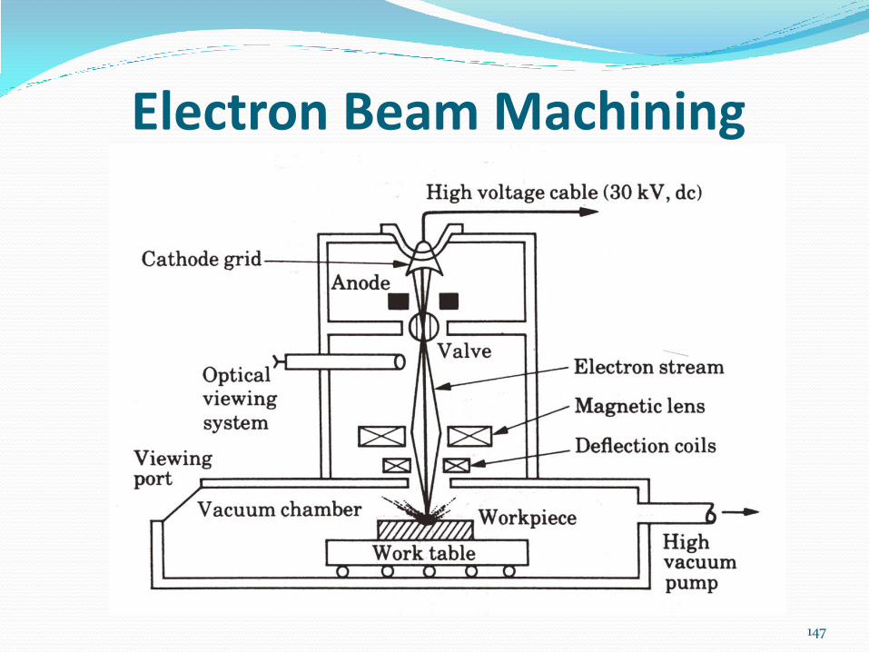
Electron Beam Machining
149
Plasma Arc Cutting Plasma is a stream of ionized gas
Typical temperatures are very high
Same process as plasma welding, without filler metal
Torch movement controlled by computer
Power requirements depend on material being cut,
plus depth of cut
Recast layer is deeper than with other processes

151
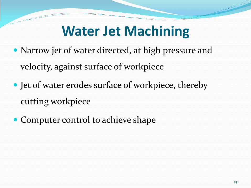
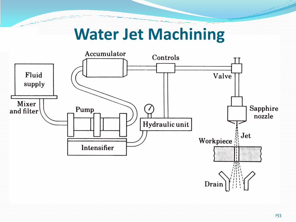
Water Jet Machining Narrow jet of water directed, at high pressure and
velocity, against surface of workpiece
Jet of water erodes surface of workpiece, thereby
cutting workpiece
Computer control to achieve shape
153
Water Jet Machining
155
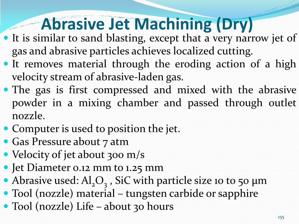
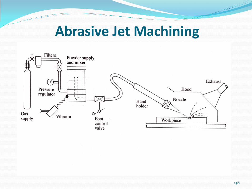
Abrasive Jet Machining (Dry) It is similar to sand blasting, except that a very narrow jet of
gas and abrasive particles achieves localized cutting. It removes material through the eroding action of a high
velocity stream of abrasive-laden gas. The gas is first compressed and mixed with the abrasive
powder in a mixing chamber and passed through outlet nozzle.
Computer is used to position the jet. Gas Pressure about 7 atm Velocity of jet about 300 m/s Jet Diameter 0.12 mm to 1.25 mm Abrasive used: Al2O3 , SiC with particle size 10 to 50 µm Tool (nozzle) material – tungsten carbide or sapphire Tool (nozzle) Life – about 30 hours
156
Abrasive Jet Machining
Advantages of AJM Can be used in any material, conductive, non-
conductive, ductile or brittle
Good dimensional accuracy (±0.05 mm)
Good Surface finish – 0.25 to 1.25 µm
Due to cooling action of gas stream no thermal damage
on the work surface
Due to negligible force delicate workpiece can be
machined.
Disadvantages of AJM Low MRR
Possibility of stray cutting
Embedding of abrasive particles in soft workpiece
Dust control needed
Application of AJM Cutting and drilling on metal foils and thin
sections of ceramics and glass
Intricate holes in electronic components such as
resistor paths in insulation
Engraving of characters on toughened glass
automobile windows
Cleaning, polishing and deburring the surface
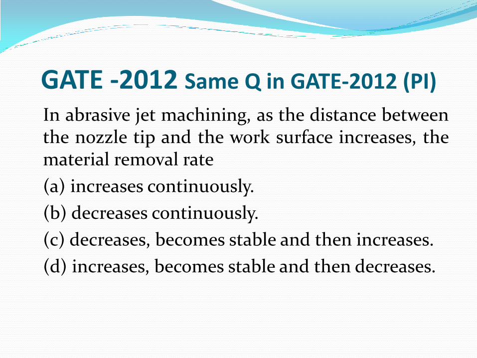
GATE -2012 Same Q in GATE-2012 (PI)
In abrasive jet machining, as the distance between the nozzle tip and the work surface increases, the material removal rate
(a) increases continuously.
(b) decreases continuously.
(c) decreases, becomes stable and then increases.
(d) increases, becomes stable and then decreases.
Abrasive WJ Cutting Used to cut much harder materials
Water is not used directly to cut material as in Pure,
instead water is used to accelerate abrasive particles which
do the cutting
80-mesh garnet (sandpaper) is typically used though 50
and 120-mesh is also used
Standoff distance between mixing tube and workpart is
typically 0.010-0.200 – important to keep to a minimum to
keep a good surface finish
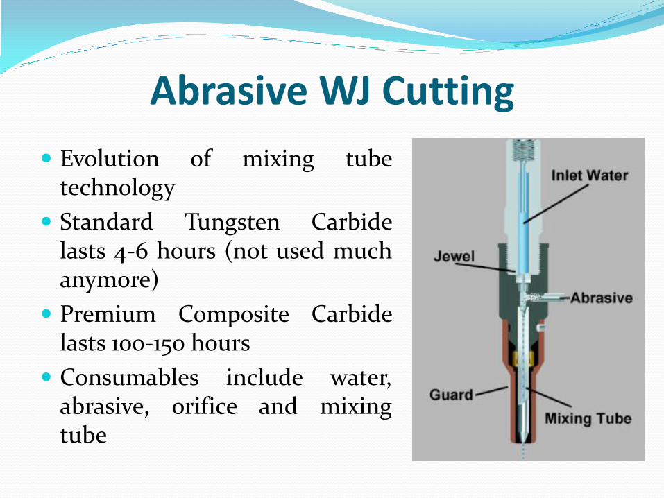
Abrasive WJ Cutting
Evolution of mixing tube technology
Standard Tungsten Carbide lasts 4-6 hours (not used much anymore)
Premium Composite Carbide lasts 100-150 hours
Consumables include water, abrasive, orifice and mixing tube


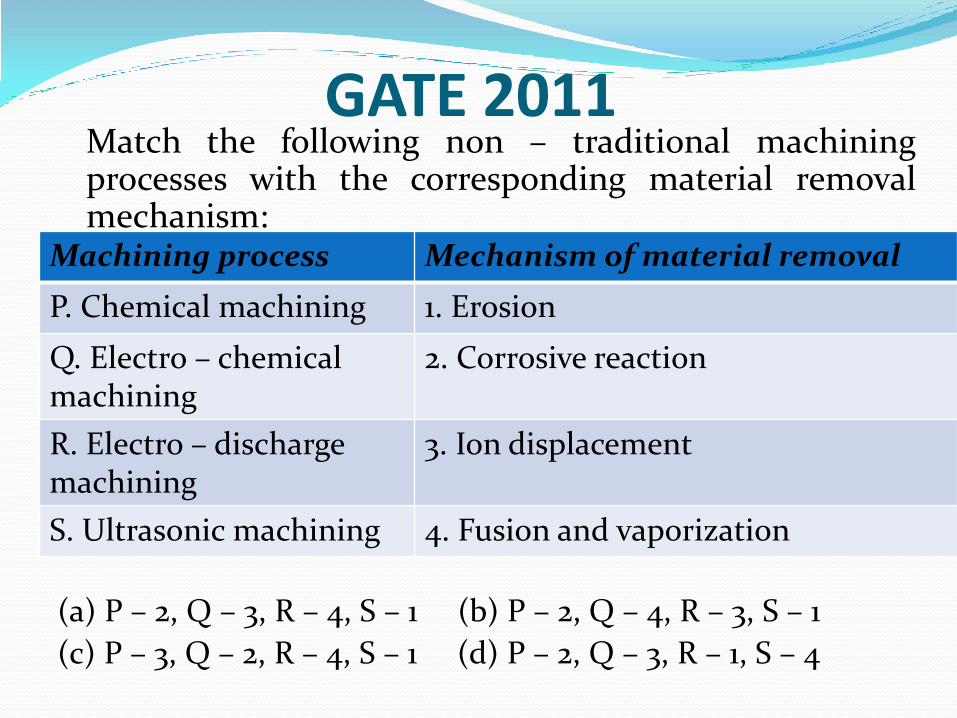
GATE 2011 Match the following non – traditional machining
processes with the corresponding material removal mechanism:
(a) P – 2, Q – 3, R – 4, S – 1 (b) P – 2, Q – 4, R – 3, S – 1
(c) P – 3, Q – 2, R – 4, S – 1 (d) P – 2, Q – 3, R – 1, S – 4
Machining process Mechanism of material removal
P. Chemical machining 1. Erosion
Q. Electro – chemical machining
2. Corrosive reaction
R. Electro – discharge machining
3. Ion displacement
S. Ultrasonic machining 4. Fusion and vaporization

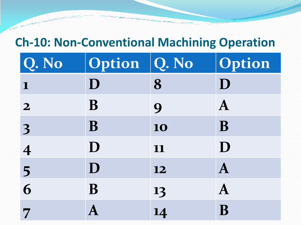
Ch-10: Non-Conventional Machining Operation
Q. No Option Q. No Option
1 D 8 D
2 B 9 A
3 B 10 B
4 D 11 D
5 D 12 A
6 B 13 A
7 A 14 B