Embed Size (px)
Citation preview
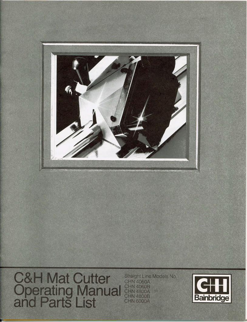
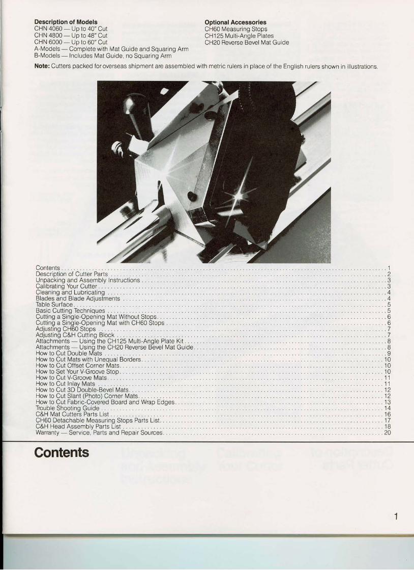
Description of ModelsCHN 4060 - Uo to 40" CutCHN 4800 - Up to 48" CutCHN 6000 - Up to 60" CutA-Models - Complete with Mat Guide and Squaring ArmB-Models - Includes Mat Guide, no Squaring Arm
Note: Cutters packed for overseas shipment are assembled with metrlc rulers in place of the English rulers shown in il lustrations.
Contents . . . . . .1oesci ipt ionof CutterPai ts. . . . . . . : : . . . . . . . . . . 2UnpackingandAssemblylnstruct ions . . . . .3Cal ibrat inoYourCutter . . . . . . . . .3Cleaningindlubr icat ing. , , . . . . . . . . . . .4BladesandBladeAdjustments . . . . . . . .4TableSurface . . . . . . . . . .5BasicCutt inqTechnioues . . . . . .5Cutt ingaSin"gle-Opening MatWithoutStops.. . . . . . . . . .6Cutt in laSin[ le-Oi:enin! MatwithCH6OStops. . . . . . . . 6Adjust lngCH60Stops . . . . . . . . .7Adjust ing C&H Cutt ing Block . . . . . . . . .7Attachments- Using the CH125 Mult i -Angle Plate Ki t . . . . . . . . 8Attachments - Usino the CH20 Reverse Bevel Mat Guide. . . . . . 8HowtoCutDoubleM"ats . . . . .9How to Cut Mats with Uneoual Borders. 10How to Cut Offset Corner Mats, , . . . 10How to Set Your V-Groove Stop . . . . . 10Howto CutV-Groove Mats. , . . . .11HowtoCut ln lavMats , , . . . . . . .11How to Cut 3D Double-Bevel Mats, . . . . .12HowtoCutSlant(Photo)Corner Mats, , , . . . . . . .12How to Cut Fabric-Covered Board and Wrap Edges. . . . . 13TroubleShoot inq Guide. . . . . . . .14C&H Mat Cuttefs Parts List . 16CH60 Detachable Measur ing Stops Parts List , . .17C&H Head Assemblv Parts List 18Warranty-Service, 'Parts and Repair Sources. . . . . . . . .20
Gontents
Optional AccessoriesCH60 Measuring StopsCH1 25 Mult i -Angle PlatesCH20 Reverse Bevel Mat Guide
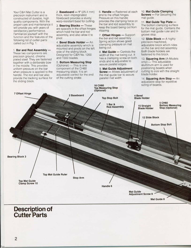
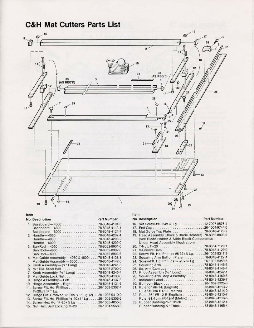
Your C&H Mat Cutter is aprecision instrument and isconstructed of durable, h ighquality components, With theproper care and maintenance itwil l provide you with years ofsatisf actory performance.Familiarize yourself with thefunction and the features of thefollowing l ist of cutter partscal led out in Flg. 1:
1. Bar and Rod Assembly -These two components areprecis ion ground, chromeplated steel. They are fastenedtogether with a deliberate bowin the middle. This providesuniform pressure on the barwhen pressure is applied to thehandle. The rod and bar alsoprovide the tracking surface forthe s l id ing block.
2, Baseboard - 1'(25 4 mm)thick, resin-impregnatedfibreboard provides a sturdy,warp-resistant base for cutting.
3. Bearing Blocks - Theseare spacers in the offset hingeswhich hold the bar and rodassembly, and also allow it tooivot.
4. Bevel Blade Holder - Anadjustable assembly whlch ismounted and pivots on the lefts ide of the s l id ing blockDesigned for C&H No. 1200and 15C0 blades.
5. Bottom Measuring Stop(Opt ional) - This is onecomponent of the CH60measuring stops. lt is anadlustable control for the endof the cutting stroke.
6. Handle - Fastened at eachend to the offset hinges,Pressure on this handleprovides the clamping force onthe bar and rod assembly tokeep the board being cut fromsl ipping.
7. Offset Hinges - SuPPortthe bar and rod assemblY.Spring action allows goodclamping pressure on matbeing cut.
8. Mat Guide - Controls thewidth of the mat being cut. lthas a clamping screw on bothends and ls adjustable toassure parallel edges.
9. Mat Guide AdjustmentScrew - Allows adjustment ofthe mat guide bar to assureoarallel mat width.
10. Mat Guide ClampingScrews - For Securing themat guide.
11. Mat Guide Top Plate -The bottom clamping surfacefor the mat gulde, Contains thebottom mat guide ruler and V-groove srop.
12. Sl ide Block - A highlyorecis ion-machined,adjustable block which r ideson the bar and rod assembly.Both blade holders arefastened to this block.
13. Squaring Arm (A-Modelsonly) - Thls adjustablealuminum arm is used forposi t ioning boads whencutting to size with the straightblade holder.
14. Squaring Arm Stop - Anadjustable stop for repetit ivesizing of boards,16 CH60
Top Measuring StoP(Optional)
7 Offset Hinge
Bearing Block 3
2 Baseboard
Stop Arm
Top Stop Bolt
1 Bar&Rod AssemblY
.', ::
Handle 6
4 BevelBlade Holder
12 Slide Block
Mat GuideAdiustment Screw 9
5 CH6015 Straiqht Bottom MeasuringBlade H-older StoP (OPtional)
Bottom Stop Bolt
Top Mat Guide Ruler
Top Mat GuideClamp Screw 10
Description ofCutterParts
Mat Guide 8
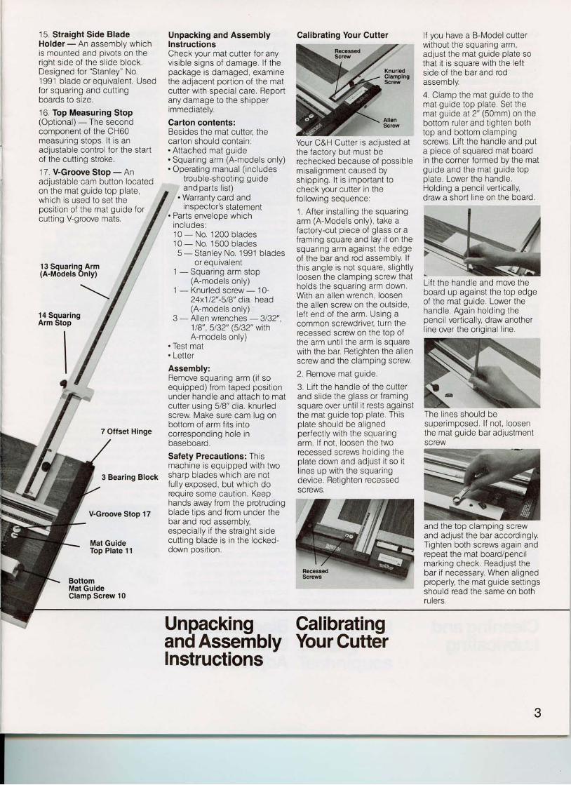
15. Straight Side BladeHolder - An assernbly whichis mounted and pivots on ther ight s ide of the s l ide block.Designed for "Stanley" No.1991 blade or equivalent. Usedfor squar ing and cutt ingboards to size.
16. Top Measuring Stop(Optional) - The secondcomponent of the CH60measur lng stops. l t is anadlustable control for the startof the cutting stroke.
17. V-Groove Stop - Anadjustable cam button locatedon the mat guide top plate,which is used to set theposi t ion of the mat guide forcutting V-groove mats.
13 Squaring Arm(A-Models Only)
14 SquaringArm Stop
7 Offset Hinge
3 Bearing Block
V-Groove Stop 17
Mat GuideTop Plate 11
BottomMat GuideClamp Screw 10
Unpacking and AssemblyInstructionsCheck your mat cutter for anyvis ib le s igns of damage. l f thepackage is damaged, examinethe adjacent portion of the matcutter wlth speclal care. Reportany damage to the shipperlmmediately.
Garton contents:Besides the mat cuttet thecarton should contain:. Attached mat guide. Squar ing arm (A-models only). Operat ing manual ( includes
trouble-shoot ing guide
lf you have a B-Model cutterwi thout the squar ing arm,adjust the mat guide plate sothat it is square with the leftside of the bar and rodassemory.
4. Clamp the mat guide to themat guide top plate. Set themat guide at 2" (50mm) on thebottom ruler and tighten bothtop and bottom clampingscrews. Li f t the handle and puta piece of squared mat boardin the corner formed by the matguide and the mat guide topplate. Lower the handle.Holding a penci l vert ical ly,draw a short l ine on the board.
Lift the handle and move theboard up against the top edgeof the mat guide, Lower thehandle. Again holding thepencil vertically, draw anotherl ine over the or ig inal l ine.
super imposed. l f not , loosenthe mat guide bar adjustmentSCTCW
and the top clamping screwand adjust the bar accordingly.Tighten both screws again andrepeat the mat board/pencilmarking check. Readjust thebar if necessary. When alignedproperly, the mat guide settingsshould read the same on bothruters.
Your C&H Cutter ls adjusted atthe factory but must berechecked because of possiblemisal ignment caused byshipping. l t is important tocheck your cut ter in thefol lowing sequence:
1 . Af ter instal l ing the squar lngarm (A-Models only), take afactory-cut piece of glass or aframing square and lay it on thesquar ing arm against the edgeof the bar and rod assembly. lfth is angle is not square, s l ight lyloosen the clamping screw thatholds the squar ing arm down,With an al len wrench, loosenthe allen screw on the outside,lef t end of the arm. Uslng acommon screwdriver, turn therecessed screw on the top ofthe arm unt i l the arm is squarewith the bar, Retlghten the allenscrew and the clamping screw
2, Remove mat guide,
3. Lift the handle of the cutterand sl ide the glass or f ramingsquare over unti l i t rests againstthe mat guide top plate. Thisplate should be al ignedperfectly wlth the squaringarm. lf not, loosen the tworecessed screws holding theplate down and adjust it so itl ines up with the squar ingdorr inp Rot inhtcn rcccsgg6l| ,vL,v, , lv l
SCTCWS.
. and parts list),,, . Warranty card and
inspector's statemenl. Parts envelope which
includes:10 - No. 1200 blades10 - No. 1500 blades5 - Stanley No. 1991 blades
or equivalent1 - Squar ing arm stop
(A-models only)I - Knur led screw - 10-
24x112"-518" dia. head(A-models only)
3 - Allen wrenches - 3132',118',, 5132" (5/32" withA-models only)
. Test mat
. Letter
Assembly:Remove squaring arm (if soequipped) f rom taped posi t ionunder handle and attach to matcutter using 5/8" dia. knur ledscrew Make sure cam lug onbottom of arm fits intocorresponding hole lnbaseboard.
Safety Precautions: Thismachine is equipped with twosharp blades which are notful ly exposed, but which dorequire some caut ion, Keephands away from the protrudingblade t ips and from under thebar and rod assembly,especial ly i f the straight s idecutt ing blade is in the locked-down position,
Unpackinq Calibratinqand AsseffibV Your Guttdrlnstructions
3
Calibrating Your Cutter
The l ines should be
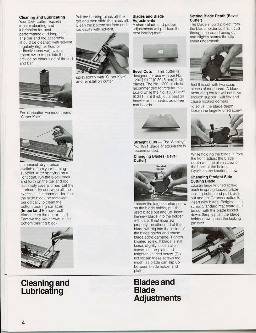
Cleaning and LubricatingYour C&H cutter requiresregular c leaning andlubrication for bestperformance and longest l i fe.The bar and rod assemblyshould be cleaned with solventregular ly ( l ighter f lu id oradhesive remover), Use acotton swab to get lnto thecrevice on either side of the rodano oar
For lubrication we recommend"Super-Kote",
an aerosol , dry lubr icanL,available from your framingsuppl ier . Af ter spraying on al ight coat, run the block backand forth on the bar and rodassembly several t imes. Let thelubr icant dry and wipe of f theexcess, lt is recommended thalthe slide block be removedper iodical ly to c lean thebottom bearing surfaces.(lmportant! Remove bothblades from the cutter f i rst ! )Remove the two screws in thebottom bearing block,
Pul l the bear ing block of f therod and then slide the block offClean the bottom surface androd cavity with solvent,
Blades and BladeAdjustmentsA sharp blade and properadjustments wi l l produce thebest looking mats.
Setting Blade Depth (BevelCuttet)The blade should project fromthe blade holder so that l t cutsthrough the board being cutand sl ight ly scores the s l iPsheet underneath.
Test this out with two scrappieces of mat board. A bladeprotruding too far wil l not haveenough support , wi l l f lex andcause hooked corners.To adjust the blade depth,loosen the large knurled screw
Whi le holding the blade in f romthe front, adjust the bladedepth with the allen screw onthe back of the holder.Retlghten the knurled screw
Changing Straight SideCutting BladeLoosen large knurled screw,push in spr ing- loaded bladelocking button and pul l b ladeout and up, Depress button toinsert new blade Retighten thescrew Standard mat board canbe cut wi th the blade lockeddown Simply push the bladeholder down, push the lockingpin over
spray l lghtly with "Super-Koteand reinstall on cutter.
Bevel Cuts - This cutter isdeslgned for use wlth our No.1200 [ .012' (0,3048 mm) thick]blades. The No. 1200 blade isrecommended for regular matboard whi le the No 1500 [ .015'(O 381 mm) thickl cuts best onheavier or the harder, acidjreemat boards,
Straight Cuts - The "StanleY"No. .1991 Blade or equivalent isrecommended.
Ghanging Blades (BevelCutter)
Loosen the large knurled screwon the blade holder, pul l theused blade out and up. Insertthe new blade into the holderwith care. lf not insertedproperly the other end of theblade wi l l d ig into the inside ofthe blade holder and causeblade edge damage. Tightenknur led screw. l f b lade is st l l lloose, s l ight ly loosen al lenscrews on top plate andretighten knurled screw (Donot loosen these screws toomuch, as blade can sl ip upbetween blade holder andplate.)
Cleaninq andLubricating
Blades andBlade
4
Adjustments
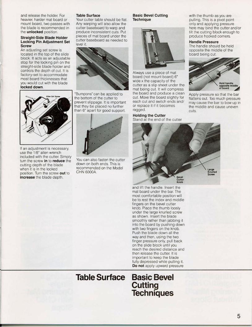
and release the holder. Forheavier, harder mat board ormount board, two passes withthe blade is recommended inthe unlocked positlon.
Straight-Side Blade HolderLocking Pin Adjustment SetScrewAn adjusting set screw islocated in the too of the slideblock. lt acts as an adjustablestop for the locking pln on thestraight-s ide blade holder andcontrols the depth of cut . l t isfactory-set to accommodatemost board thicknesses thatyou would cut wi th the bladelocked down.
lf an adjustment is necessary,use the 1/8" al len wrenchlncluded with the cutter. Simplyturn the screw in to reduce thecutt ing depth of the bladewhen it is in the lockedposition. Turn the screw out toincrease the blade depth,
Table SurfaceYour cut ter table should be f lat .Any warping wil l also allow thecutter baseboard to waro andproduce inconsistent cuts. Putpieces of mat board under thecutter baseboard as needed tolevel it.
"Bumpons" can be appl ied tothe bottom of the cutter toprevent slippage. lt is importantthat they be placed no furtherthan 6" apart for good support.
You can also fasten the cutterdown on both ends. This isrecommended on the ModelCHN 60004.
Basic BevelCuttingTechnique
Always use a piece of matboard (not mount board) 6"wide x the capacity of thecutter as a s l ip sheet under themat being cut. l t wi l l compressthe board and produce a cleancut, Move the board slightly foreach cut and switch ends and/or replace it i f i t becomesraggeo.
Holding the CutterStand at the end of the cutter
and l i f t the handle. Insert themat board under the bar, Themost comfortable position wil lbe to rest the index and middlefingers on the bevel cutterknob. Place the thumb looslyunder the large knurled screwas shown. lnsert the bladesmoothly rather than jabbing itinto the board by pushing downwith two fingers on the knob.Push the blade down al l theway and then, using the twof inger pressure only, pul l backon the sl ide block unt i l youreach the desired distance andthen release the cutter, lt isimportant to keep the bladeful ly depressed whi le pul l ing i t .Do not apply upward pressure
with the thumb as you arepul l ing. This is a pivot pointonly and apply ing pressurehere may bind the cutter and/ort i l t the cut t ing block enough toproduce hooked corners.
Handle PressureThe handle should be heldopposi te the middle of thehna rc l hoinn nr r t
Apply pressure so that the barflattens out. Too much pressuremay cause the bar to bow up inthe middle and cause unevencuts.
Table Surface Basic Bevel
5
CuttinqTechnilues
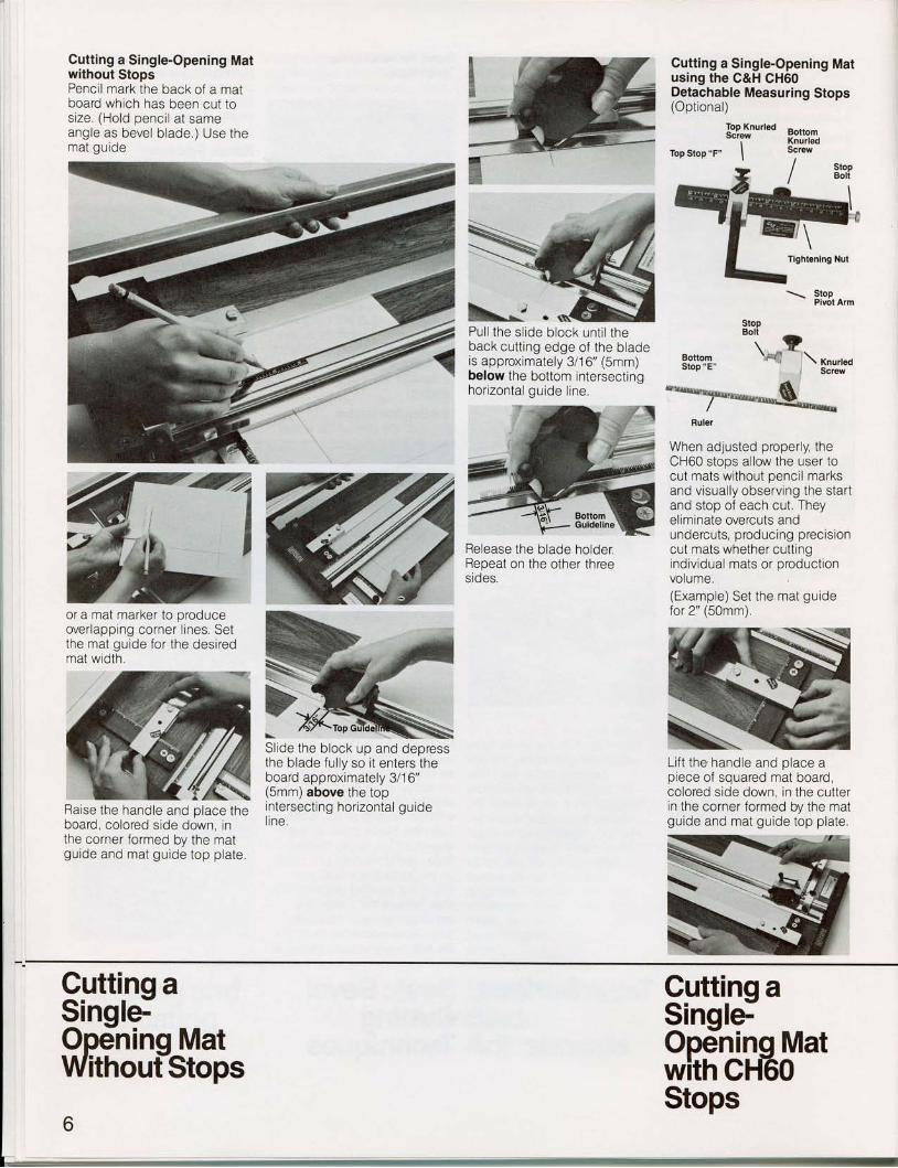
Cutting a Single-Opening Matwithout StopsPencil mark the back of a matboard which has been cut tosize. (Hold penci l at sameangle as bevel b lade.) Use themat guide
Cutting a Single-Opening Matusing the C&H CH60Detachable Measuring Stops(Optional)
Top Stop "F"
Top KnurledScrew
II
BottomKnurledScrew
/ stop
/ Bolt
Pul l the s l ide block unt i l theback cutt ing edge of the bladeis approximately 3/16" (5mm)below the bottom intersectinghor izontal guide l ine.
Release the blade holder.Repeat on the other threesides.
Stopt"\ ?
Pgttq|I.. ',*q \ KnurredStop "E" - b"r"*
Ruler
When adjusted properly, theCH60 stops allow the user tocut mats without pencil marksand visual ly observing the startand stop of each cut. Theyeliminate overcuts andundercuts, producing precis ioncut mats whether cuttinglndiv idual mats or product ionvolume.(Example) Set the mat guidefor 2" (50mm).
Li f t the handle and place aplece of squared mat board,colored side down, in the cutterin the corner formed by the matguide and mat guide top plate.
or a mat marker to produceover lapping corner l ines, Setthe mat guide for the desiredmat width.
Raise the handle and place theboard, colored side down, inthe corner formed by the matguide and mat guide top plate.
Sl ide the block up and depressthe blade ful ly so i t enters theboard approximately 3/1 6"(5mm)above the topintersect ing hor izontal guidel ine,
\_ StopPivot Arm
Cuttin Cuttinq aSingldOpeninq Matwirh cH60
Sinqle-Opdninq MatWitnout-Stops
Stops

(read all stoos on the side withthe arrow that says "read rulerhere"). Position the top stop sothat the arm rests against thetop edge of the board.
(Don't hlt the stops too hard asthey may move,) Release bladeholder. Repeat on oppositeside and then reposition topstop only for other dimension ofboard and cut both sides.
Mat Gulde Bal
Place the stops on the rod andset the top stop at 2" (50mm)by loosenlng the top knur ledSCTEW
Depress the blade all the wayinto the mat board. Pull thesl ide block down unt i l i t h i ts thebottom stop,
Adjusting CH60 StopsBesides these adjustments, itshould be noted that unsquareboards. improper blade depthand inconsistent technique canalso cause cutting variables.To adjust and correct overcutsor undercuts, check each cuton the back of the board. Thebeginning of the cut (top stop)should start 3/16" (5mm)above the top intersectinghorizontal cut. Llkewise, theend of the cut (bottom stop)should stop 3/16" (5mm) belowthe bottom intersecting cut.
lf not, adjustments arerequired. To correct overcutson the top stop, loosen the nuton the stop bolt
and screw the bolt out (towardthe mat), To correct undercutsscrew the bolt in (awav from themat). The bottom stop can beadiusted the same wav
Adjusting C&H Cutting BlockNote: The block on your newcutter has been adlusted at thefactory and should not requirefurther calibration before use.1 l f adir rctmonte 2ro
necessary, use the tworecessed allen screws
on the straight cutter side ofthe block Before adjust ing,remove the block from the bar/rod and clean and lubricateinside the block cavity and thebar/rod (see Cleaning andI r rhr inai inn coni inn\
,Y vvv(,v, , / .
2. Reinstal l b lock and sl ideback and forth to f ind t ightestspot on bar/rod. Adjust theblock in th is area,3 Adjust one screw at a time,Screw it in unti l the block won'tmove. Then back the screw ouls l ight ly, ,unt i l the block s l idessmoothly the whole length ofthe barlrod. Repeat procedureon the other screwTighten in place with large
knurled screwSet the bottom stop at 2(50mm)and t ighten down hardwith the knurled screw
Sl ide the cutt ing block up unt i li t touches the stop bolt.
Tighten nuts after adjustmenl
Adiustinq AdiustinqCFI60 Sto-ps C&H CutTing
Block
7
Diamond Plate 6.side Plalo
(o)t\#
/A(n><^\-x\Z,,TS
I ILU<F "D" stop
(0.635 mm)0""25"+
6".25"+(152.4.635 mm) 2 Rulers
8.side Plats
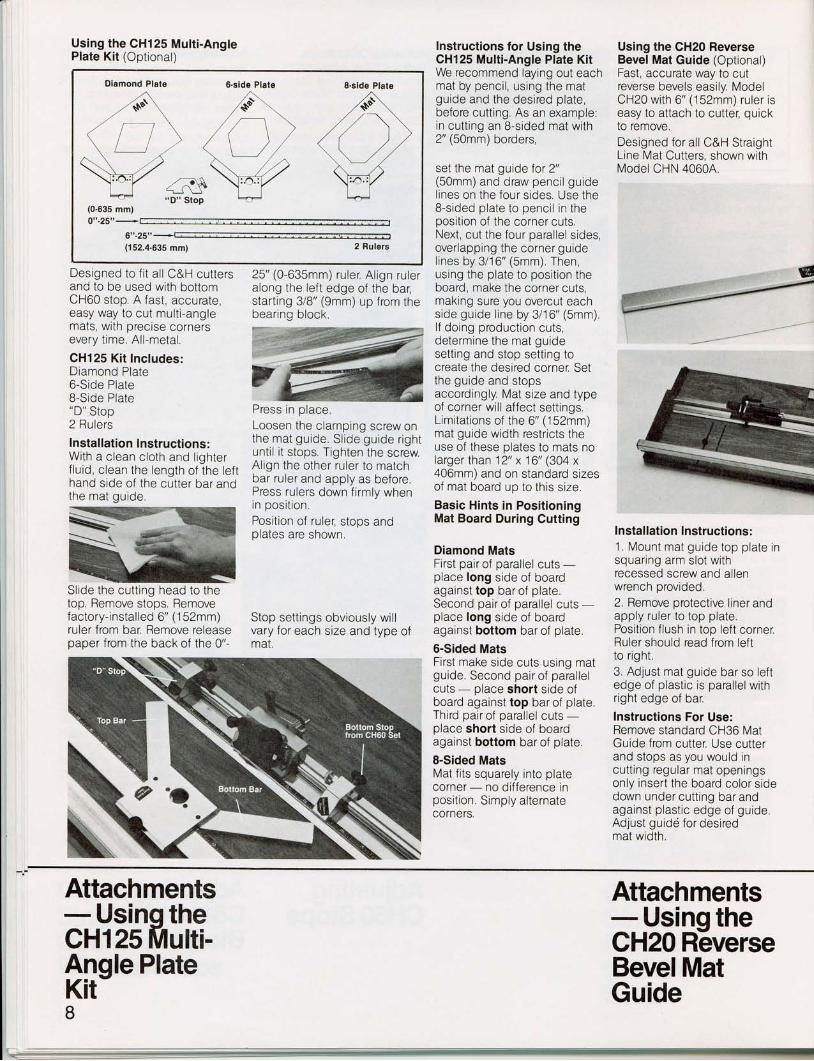
Using the CH125 Multi-AnglePlate Kit (Optional)
Designed to f i t a l l C&H cuttersand to be used with bottomCH60 stop. A fast, accurate,easy way to cut multi-anglemats, with precise cornersevery time. All-metal.
CH125 Ki t Includes:Diamond Plate6-Side Plate8-Side Plate'D" Stop2 Rulers
lnstallation lnstructions:With a c lean cloth and l ighterf lu id, c lean the length of the lef thand side of the cutter bar andthe mat guide.
Slide the cutt ing head to thetoo. Remove stoos, Removefactory- instal led 6" (1 52mm)ruler from bar. Remove releasepaper from the back of the 0"-
25" (0-635mm) ruler. Al ign ruleralong the lefl edge of the bar,starting 3/8" (9mm) up from thebearing block.
Press in place.Loosen the clamping screw onthe mat guide. Sl ide guide r ightunti l i t stops. Tighten the screwAl lgn the other ruler to matchbar ruler and apply as before.Press rulers down flrmly whenin posi t ion.Position of rule; stops andnlatac aro chnrrrn
Stop settlngs obviously wil lvary for each size and type ofmat,
lnstructions for Using theCH125 Multi-Angle Plate KitWe recommend laying out eachmat by pencil, using the matguide and the desired plate,before cutting. As an example:in cutting an 8-sided mat with2" (50mm) borders,
set the mat guide for 2"(50mm)and draw penci l guidel ines on the four s ides. Use the8-sided plate to penci l in theposition of the corner cuts.Next, cut the four parallel sides,overlapping the corner guidel ines by 3/16" (5mm). Then,using the plate to position theboard, make the corner cuts,making sure you overcut eachside guide l ine by 3/16" (5mm).l f doing product ion cuts,determine the mat guidesetting and stop setting tocreate the desired corner. Setthe guide and stopsaccordingly. Mat size and typeof corner wil l affect settings.Limitat ions of the 6" (152mm)mat guide width restricts theuse of these plates to mats nolarger than 12" x 16" (304 x406mm) and on standard sizesof mat board up to this size.
Basic Hints in PositioningMat Board During Gutting
Diamond MatsFirst oair of parallel cuts -place long side of boardagainst top bar of plate.Second pair of oarallel cuts -place long side of boardagainst bottom bar of plate.
6-Sided MatsFirst make side cuts using matguide. Second pairof paral le lcuts - place short side ofboard against top bar of plate.Third pair of parallel cuts -place short side of boardagainst bottom bar of plate.
8-Sided MatsMat fits squarely into platecorner - no difference inposi t ion. Simply al ternatecorners.
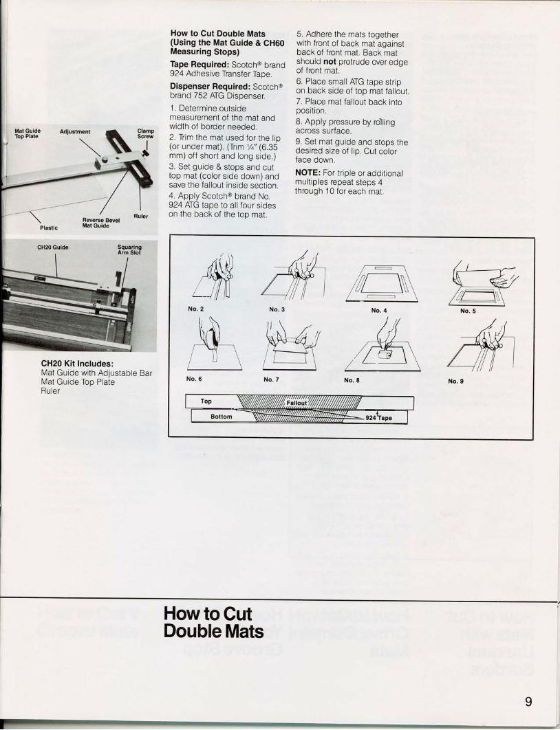
Using the CH20 ReverseBevel Mat Guide (Optional)Fast, accurate way to cutreverse bevels easily. ModelCH20 with 6" (152mm) ruler iseasy to attach to cutter, quickto remove.Designed for all C&H StraightLine Mat Cutters, shown withModel CHN 40604.
Installation lnstructions :1. Mount mat guide top plate insquaring arm slot withrecessed screw and allenwrench provided.2. Remove protective l iner andapply ruler to top plate,Position flush in top left cornerRuler should read from leftto right3. Adjust mat guide bar so leftedge of plastic is parallel withright edge of bar.
Instructions For Use:Remove standard CH36 MatGuide from cutter. Use cutterand stops as you would incutt ing regular mat openingsonly insert the board color sidedown under cut t ing bar andagainst p last ic edge of guide.Adjust guidd for desiredmat width.
Attachments- Usinq theCH125 Mufti-Anqle PlateKit-
Attachments- Usinq theCH20 R6verseBevel MatGuide
I
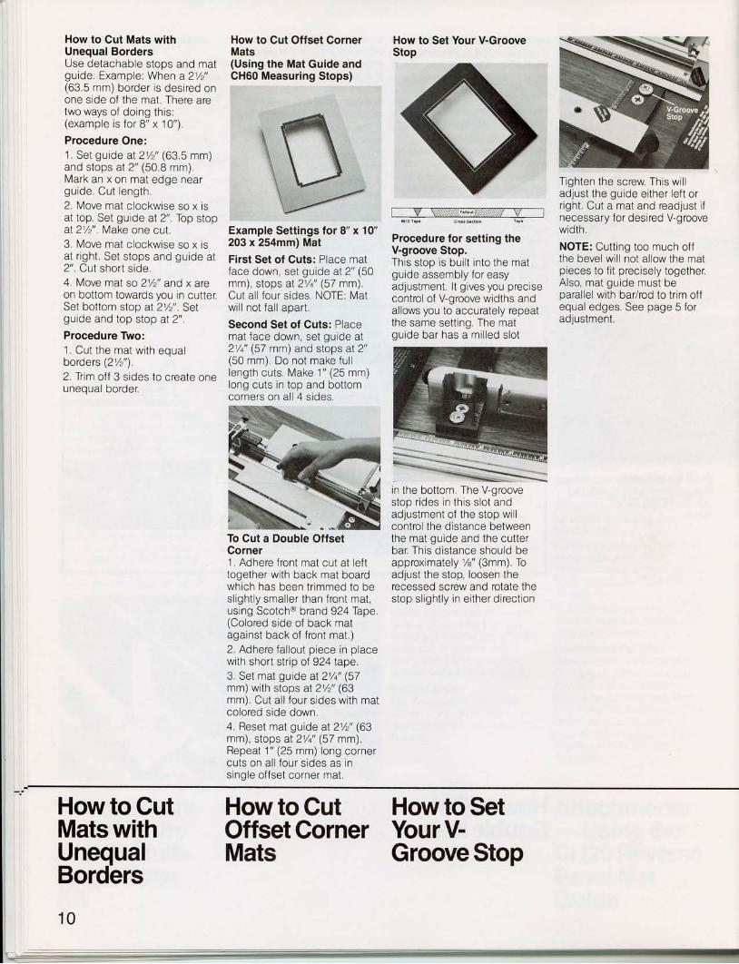
How to Cut Double Mats(Using the Mat Guide & GH60Measuring Stops)
Tape Required: Scotch@ brand924 Adhesive Transfer Tape,
Dispenser Required: Scotch@brand 752 ATG Dispenser.
l . Determine outsldemeasurement of the mat andwidth of border needed.2. Trim the mat used for the l io(or under mat). (Trim 1/+'(6.35mm) of f short and long side.)3. Set guide & stops and cuttop mat (color side down) andsave the fallout inside section.4. Apply Scotch@ brand No.924 ATG tape to all four sideson the back of the top mat.
5. Adhere the mats togetherwith front of back mat againstback of front mat, Back matshould not protrude over edgeof front mat.6. Place smal lATG tape str ipon back side of top mat fallout.7. Place mat fallout back intoposition.8. Apply pressure by roll ingacross surface,9. Set mat guide and stops thedesired size of l ip. Cut colorface down.
NOTE: For t r ip le or addi t ionalmultiples repeat steps 4through 10 for each mat.
T"iF:it"" Adiustment
\
tf
, ?:1
Feverse EevelMat Guide
SquaringArm Slol
CH20 Kit Includes:l\4at Guide wlth Adlustable BarMat Guide Top PlateRuler
\ '
Plastic
Ctl2O Guide
tzi , \ \
,14ffiL_ll ll
No. 2
lr \\I, -r\ \,W,
/ I j \
No. 6
No. 5
How to Cut
I
Double Mats
How to Cut Mats withUnequal BordersUse detachable stops and matguide. Example. When a 21/2"(63.5 mm) border is desired onone side of the mat. There aretwo ways of doing this:(example is for 8" x 10") .
Procedure One:1. Set guide al21/2" (63 5 mm)and stops at2" (50 8 mm).Mark an x on mat edge nearguide. Cut length,2. Move mat clockwise so x isat top. Set guide at 2" Top stopaI21/2" . Make one cut.3. Move mat c lockwise so x isat r ight . Set stops and guide at2". CUI short s ide,4. Move mat so 21/2" and x areon bottom towards you in cutter.Set bottom stop at 21/2". Selguide and top stop at 2"
Procedure Two:1. Cut the mat wi th equalborders (21/2").2.Tnm off 3 s ides to create oneunequal border.
How to Cut Offset CornerMats(Using the Mat Guide andCH60 Measuring Stops)
Example Settings for 8" x 10"203 x 254mm) Mat
First Set of Cuts: Place matface down, set guide aI 2" (50mm), stops ?I 21/q" (57 mm)Cut al l four s ides. NOTE: Matwi l l not fa l l apart .
Second Set of Cuts: Placemat face down, set guide at21/a' (57 mm) and stops at 2"(50 mm). Do not make ful llength cuts. Make 1" (25 mm)long cuts in top and bottomcorners on al l 4 s ides.
How to Set Your V-GrooveStop
W
Procedure for setting theV-groove Stop.This stop is bui l t into the matgulde assembly for easyadjustment. lt gives you preclsecontrol of V-groove widths andallows you to accurately repeatthe same setting. The matouide bar has a mi l led s lot
in the bottom. The V-groovestop r ides in th is s lot andadjustment of the stop wi l lcontrol the distance betweenthe mat guide and the cutterbar. This distance should beapproximately %" (3mm). Toadjust the stop, loosen therecessed screw and rotate thestop sl ight ly in ei ther direct ion
Tighten the screw This wi l ladjust the guide ei ther lef t orright. Cut a mat and readjust ifnecessary for desired V-groovewidth
NOTE: Cutting too much offthe bevel wil l not allow the matpieces to flt precisely together,Also, mat guide must beparallel with bar/rod to trim offequal edges. See page 5 foradjustment.
To Cut a Double OffsetCorner1. Adhere front mat cut at lefttogether with back mat boardwhich has been tr immed to besl ight ly smal ler than front mat,using Scotcho brand 924fape(Colored side of back matagainst back of front mat.)2. Adhere fa l lout p iece in placewith short strip of 924 tape.3. Set mat guide at 2V4" (57mm) with stops at 21/z' (63mm). Cut al l four s ides wi th matcolored side down.4. Reset mat guide aI 2Vz" (63mm), stops aI 21/q" (57 mm)Repeat 1" (25 mm) long cornercuts on al l four s ides as insingle of fset corner mat.
How to Cut How to Cut How to SetMats with Offset Corner Your V-UnequalBorders
Mats Groove Stop
10
-
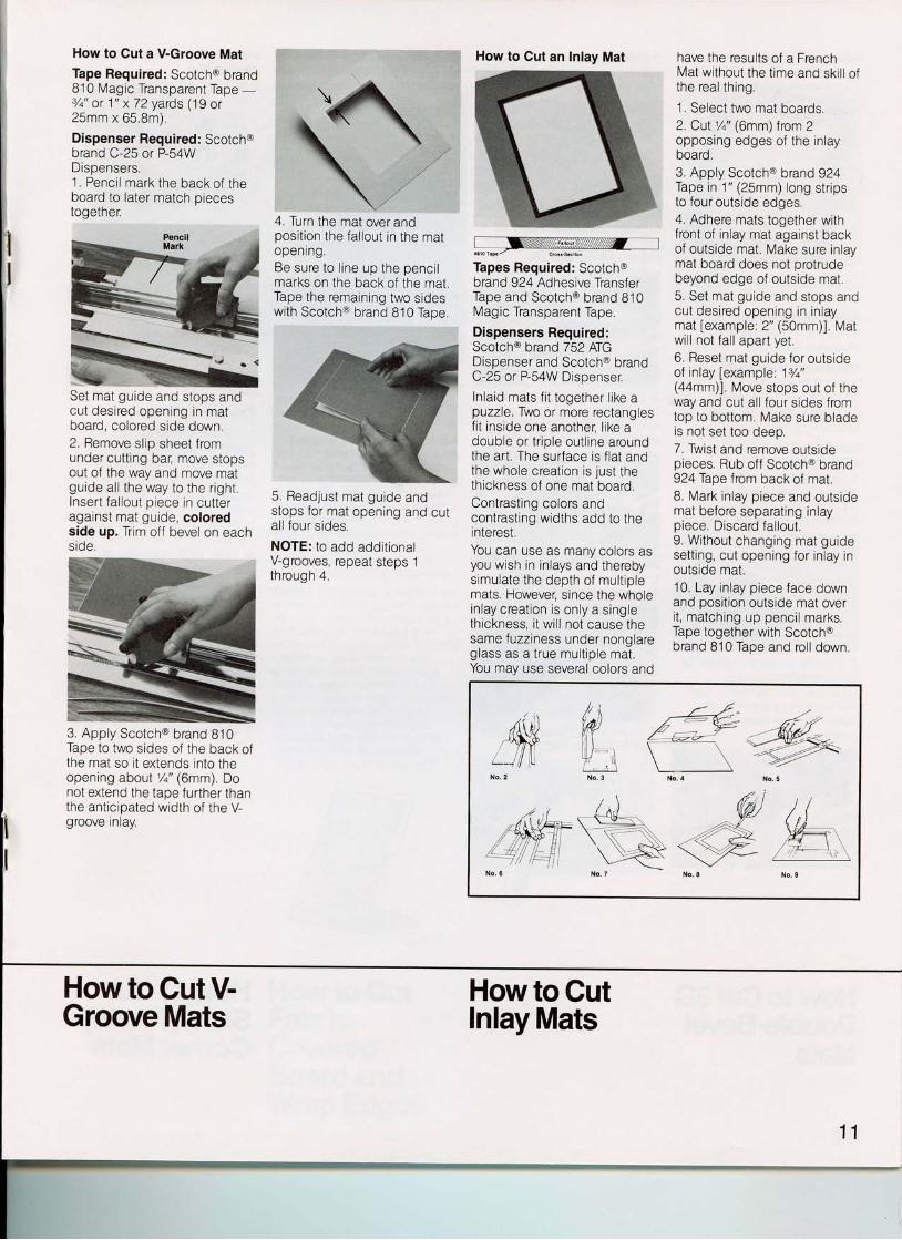
How to Cut a V-Groove Mat
Tape Required: Scotch@ brand810 Magic Transparent Tape -Tq" or 1" x 72 yards ('1 9 or25mm x 65.8m)
Dispenser Required: Scotch@brand C-25 or P-54WDispensers,1. Penci l mark the back of theboard to later match oiecestogether.
Set mat guide and stops andcut desired opening ln matboard, colored side down.2. Remove slip sheet fromunder cutting bar, move stopsout of the way and move matguide al l the way to the r ight .Insert fa l lout p iece in cut teragainst mat guide, coloredside up. Trim off bevel on eachsrde.
3. Apply Scotch@ brand 810Tape to two sides of the back ofthe mat so it extends into theopening aboul 1/q" (6mm) Donot extend the tape further thanthe anticipated width of the V-groove Inlay.
How to Cut V-
4. Turn the mat over andposition the fallout in the matopenrng.Be sure to l ine up the penci lmarks on the back of the matTape the remaining two sideswith Scotch@ brand 810 Tape
5. Readjust mat guide andstops for mat opening and culal l four s ides.
NOTE: to add additionalV-grooves, repeat steps 1through 4.
Wr6$r.p./ c'o.!.$cilon
Tapes Required: Scotch@brand 924 Adhesive TransferTape and Scotch@ brand 810Mag ic Transparent Tape.
Dispensers Required:Scotch@ brand 752 ATGDispenser and Scotch@ brandC-25 or P-54W Disoenser.
In la id mats f i t together l ike apuzzle. Two or more rectanglesf i t inside one another: l ike adouble or t r ip le out l ine aroundthe art. The surface is f lat andthe whole creation is just thethickness of one mat board.Contrasting colors andcontrasting widths add to thelnterest.You can use as many colors asyou wish in inlays and therebysimulate the depth of mult ip lemats. Howeve[ since the wholeinlay creat ion is only a s inglethickness, i t wi l l not cause thesame fuzziness under nonglareglass as a t rue mult ip le mat.You may use several colors and
How to Cut
have the results of a FrenchMat wi thout the t ime and ski l l o lthe real thing.
1. Select two mat boards.2. CuI l /q" (6mm)from 2opposing edges of the in layboard.3. Apply Scotch@ brand 924Tape in 1" (25mm) long str ipsto four outside edges.4. Adhere mats together withfront of inlay mat against backof outside mat. Make sure inlaymat board does not protrudebeyond edge of outslde mat,5. Set mat guide and stops andcut desired opening in in laymat fexample: 2" (50mm)]. Matwil l not fall apart yet,6. Reset mat guide for outsideof inlay [example: 17a"(aamm)1. Move stops out of theway and cut all four sides fromtop to bottom. Make sure bladeta nnt aat t^^. laan
7. Twist and remove outsidepieces. Rub off Scotcho brand924 fape f rom back of mat.8. Mark in lay piece and outsidemat before separating inlaypiece. Discard fallout.9. Without changing mat guidesett ing, cut opening for in lay inoutside mat.10. Lay inlay piece face downand position outside mat overi t , matching up penci l marks.Tape together with Scotch@brand 810 Tape and roll down.
How to Cut an Inlay Mat
.,($s--l ll tr
/ \ \Wt \| / : : - \
w t,i\/ . r - \
EcL]
Groove Mats Inlay Mats
11
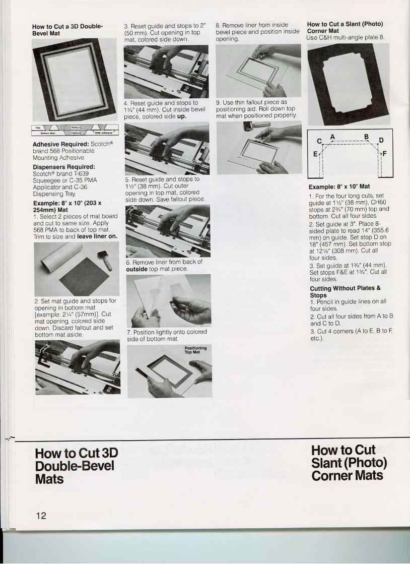
How to Cut a 3D Double-Bevel Mat
Adhesive Required: Scotch@brand 568 PositionableMount ing Adhesive.
Dispensers Required:Scotch@ brand T-639Squeegee or C-35 PMAAoolicator and C-36Dispensing Tray.
Example: 8" x 10" (203 x254mm) Mat1 Solont 2 nieceq of ma1 bOard4
Vrvvvu v ' i t iv
and cut to same size. APPIY568 PMA to back of top mat.Trim to size and leave liner on.
3. Reset guide and stops to 2"(50 mm). Cut opening in toPmat, colored side down.
8. Remove liner from insidebevel piece and position insldeopenlng.
How to Cut a Slant (Photo)Corner MatUse C&H mult i -angle plate 8
4. Reset guide and stops to13/t ' (44 mm). Cut inside bevelpiece, colored side uP.
9. Use thin fa l lout Piece aspositioning aid. Roll down toPmat when positioned ProPerlY.
7 {- -**"
2. Set mat guide and stoPs foropening in bottom matfexample: 2'/i' (57 mm)] CUImat opening, colored sidedown. Discard {al lout and setbottom mat aside.
5, Reset guide and stops to11/2" (38 mm). Cut outeropening in top mat, coloredside down. Save {al lout Piece.
6, Remove liner from back o1outside top mat Piece.
7. Position l ightly onto coloredside of bottom mat.
Example: 8" x 10" Mat
1. For the four long cuts, setguide at 11/z ' (38 mm) CH60stops at z!i ' (70 mm) toP andbottom. Cut all four sides.
2. Set guide at 3". Place 8-sided plate to read 14' (355 6mm) on guide. Set stoP D on18" (457 mm). Set bottom stopat 121/a" (308 mm) Cut allfour s ides.3, Set guide aI 13/a" (44 mm)Set stops F&E at 13/a". CUI allfour s ides.
Cutting Without Plates &Stops1 . Penci l in guide l ines on al lfour s ides.2. Cut all four sides from A to Band C to D.3. Cut 4 corners (A to E, B to Eetc.) .
c l ------ q Dl-' '- ----
Eri l ' rFi i i ii l i i
PositioningTop Mat
How to Gut 3D How to GutDouble-BevelMats
Slant (Photo)Corner Mats
1j*f,
ilw
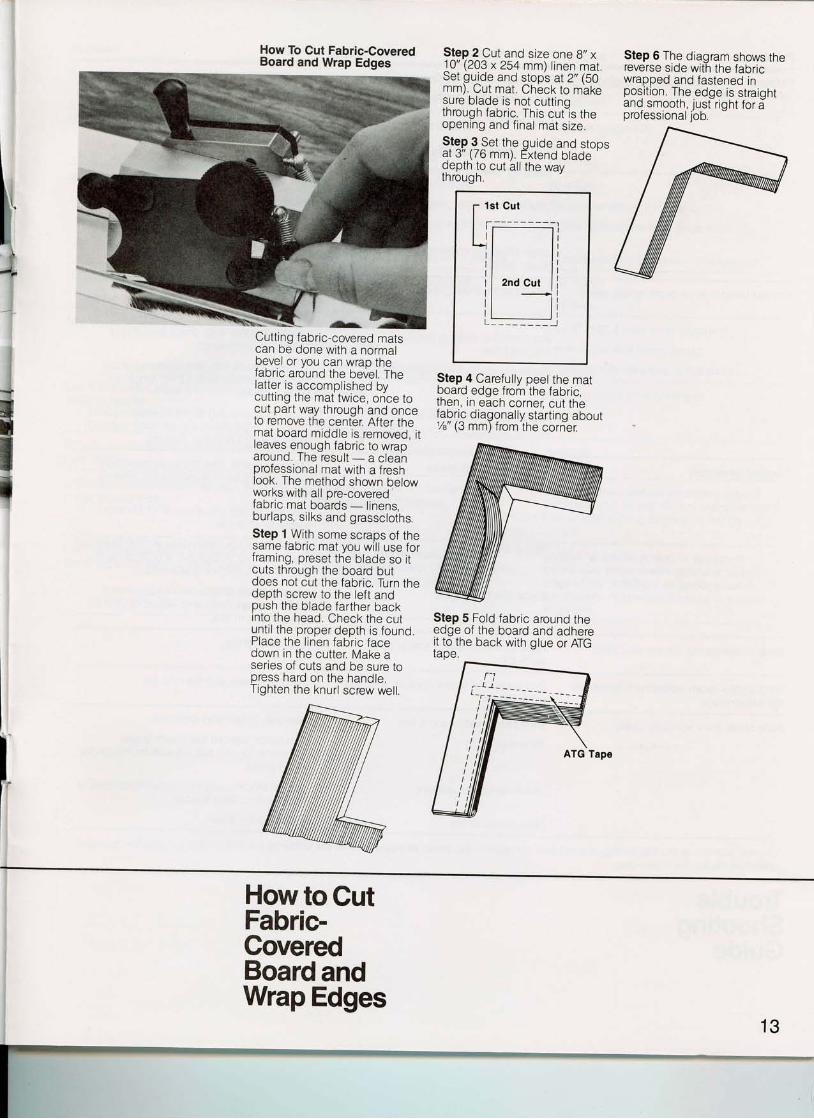
How To Cut Fabric-CoveredBoard and Wrap Edges
Cutting fabric-covered matscan be done with a normaloevet or you can wrao thefabric arciund the bevel. Thelatter is accomplished bycuttrng the mat twice, once tocut part way through and onceto remove the center. After themat board middle is removed, itleaves enough fabric to wraparound. I he resul t - a c leanprofessional mat with a freshlook. The method shown belowworks with all pre-coveredfabric mat boards - l inens,burlaps, silks and grasscloths.Step 1, With some scraps of thesame tabflc mat Vou wil l use forframing, preset the blade so itcuts through the board butdoes not cut the fabric. Turn thedepth screw to the left andpush the blade farther backinto the head. Check the cutunt i l the proper depth is found.Place the l inen fabr ic facedown in the cutter, Make aseries of cuts and be sure topress hard on the handle.Tighten the knurl screw welt.
Step 2 Cut and size one 8', x10' (203 x 254 mm) linen mar,Setguide and stop's at2,,(SOmm), Cut mat. Chbck to maxesure blade is not cut t inothrough fabric. This cut-is theopening and f inal mat s ize,Step 3 Set the guide and stoosal3" (76 mm). Extend blade 'depth to cut all the wavthrough.
Step 6 The diagram shows thereverse side with the fabricwrapped and fastened jnposi t ion. The edge is straightand smooth jusfright for aproressronal lob.
Step 4 Carefully peel the matboard edge from the fabric,Inen, In each corner, cut thefabr ic diagonal ly start ing about/B (J mm) trom tne Corner.
Step 5 Fold fabric around theedge of the board and adhereit to the back with glue or ATGtaoe.
How to CutFabric-CoveredBoard andWrap Edges
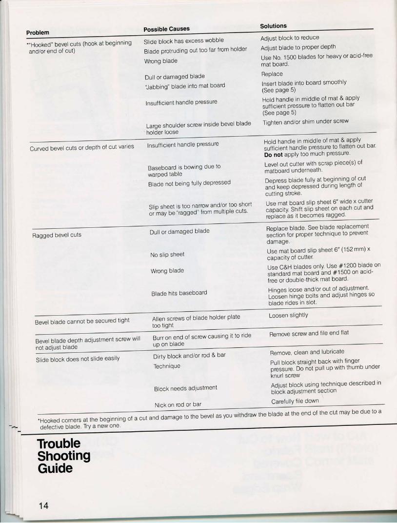
SolutionsPossible GausesProblem
-"Hooked" bevel cuts (hook at beglnningand/or end of cut)
Slide block has excess wobble
Blade protruding out too far from holder
Wrong blade
Dull or damaged blade
Jabbing' blade into mat board
Insuf f iclent handle Pressure
Large shoulder screw inside bevel blade'holder loose
Adjust block to reduce
Adjust blade to Proper depth
Use No. 1500 blades for heavy or acidJree
mat board.
Replace
lnsert blade into board smoothlY(See page 5)
Hold handle in mlddle of mat & aPPIY
sufficient pressure to flatten out bar(See page 5)
Tighten and/or shim under screw
Curved bevel cuts or depth of cut varies lnsufficient handle Pressure
Baseboard is bowing due towarped table
Blade not being fullY dePressed
Slip sheet is too narrow and/or too snort
or. tuy be "ragged" from multiple cuts
Hold handle in middle of mat & aPPIY
sufficient handle pressure to flatten out bar'
Do not aPPIY too mucn Pressure'
Level out cutter with scrap piece(s) of
matboard underneath
Deoress blade fully at beginning of cut
unil keep depressed during length ot
cutting stroke
Use mat board slip sheet 6" wide x cutter
"iiu"[V Snltt slip sheet on each cut and
replace-as it becomes ragged
Ragged bevel cuts Dul l or damaged blade
No sliP sheet
Wrong blade
Blade hits baseboard
Replace blade. See blade replacememseition for proper technique to prevent
damage.
Use mat board s l iP sheet 6" (152 mm) x
capacitY of cutter.
Use C&H blades only. Use #1200 blade on
standard mat board and #1500 on aclo-
free or double{hick mat board'
Hinqes loose and/or out of adiustment'Loolen hinge bolts and adjust hinges so
blade rides tn slot.
Bevel blade cannot be secured tight Allen screws of blade holder Plate Loosen sllghtlY
too tighl
Bevel blade depth adiustment screw wttt Burr on end of screw causing it to ride Remove screw and fi le end flat
up on bladenot adiust blade
Sl ide block does not s l ide easi lY Dirty block and/or rod & bar
Technique
Block needs adiustment
Nick on rod or bar
Remove, clean and lubrlcate
Pull block straight back with fingerpLtir" oo n6t pull up with thumb under
knurl screw
Adjust block using technique described in
block adiustment sectlon
CarefullY fi le down
;.--.----------.----.-----------* ".d
d"r"g*",f* bever as you withdraw the blade at the end of the cut may be due to a
-Hooked corners at the beginning ot
defective blade. TrY a new one
TroubleShootingGuide
14
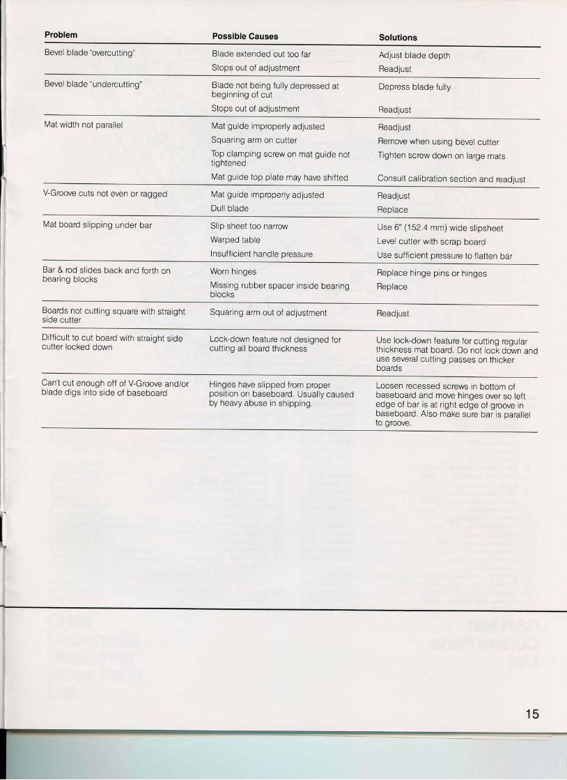
Problem Possible Causes Solutions
Bevel blade "overcutting" Blade extended out too far
Stops out of adjustment
Adjust blade depth
Readjust
Bevel blade "undercutting" Blade not being fully depressed atbeginning of cut
Stops out of adjustment
Depress blade ful ly
Readjust
Mat width not parallel Mat guide improperly adjustedSquaring arm on cutterTop clamping screw on mat guide nottightened
Mat guide top plate may have shifted
Readjust
Remove when using bevel cutter
Tighten screw down on large mats
Consult calibration section and readjusl
V-Groove cuts not even or raooed Mat guide improperly adjustedDul l blade
Readjust
Replace
Mat board s l ipping under bar Slip sheet too narrow
Warped table
Insufficient handle pressure
Use 6" (152.4 mm) wide sl ipsheet
Level cutter with scrap board
Use sufficient pressure to flatten bar
Bar & rod slides back and forth onbearing blocks
Worn hinges
Missing rubber spacer inside bear ingblocks
Replace hinge pins or hinges
Replace
Boards not cutting square with straightsrde cutter
Squaring arm out of adjustment Readjust
Diff icult to cut board with straiqht sidecutter locked down
Lock-down feature not designed forcuttlng all board thickness
Use lock-down feature for cutting regularthickness mat board. Do not lock down anduse several cutting passes on thickerDOaros
Can't cut enough off of V-Groove and/orblade digs into side of baseboard
Hinges have slipped from properposition on baseboard, Usually causedby heavy abuse in shipping.
Loosen recessed screWs in bottom ofbaseboard and move hinges over so leftedge of bar is at right edge of groove inbaseboard. Also make sure bar is parallelto groove.
15
;n"( ( )w
I r\10
' i /r /
_ _t_;
,rl
- - l
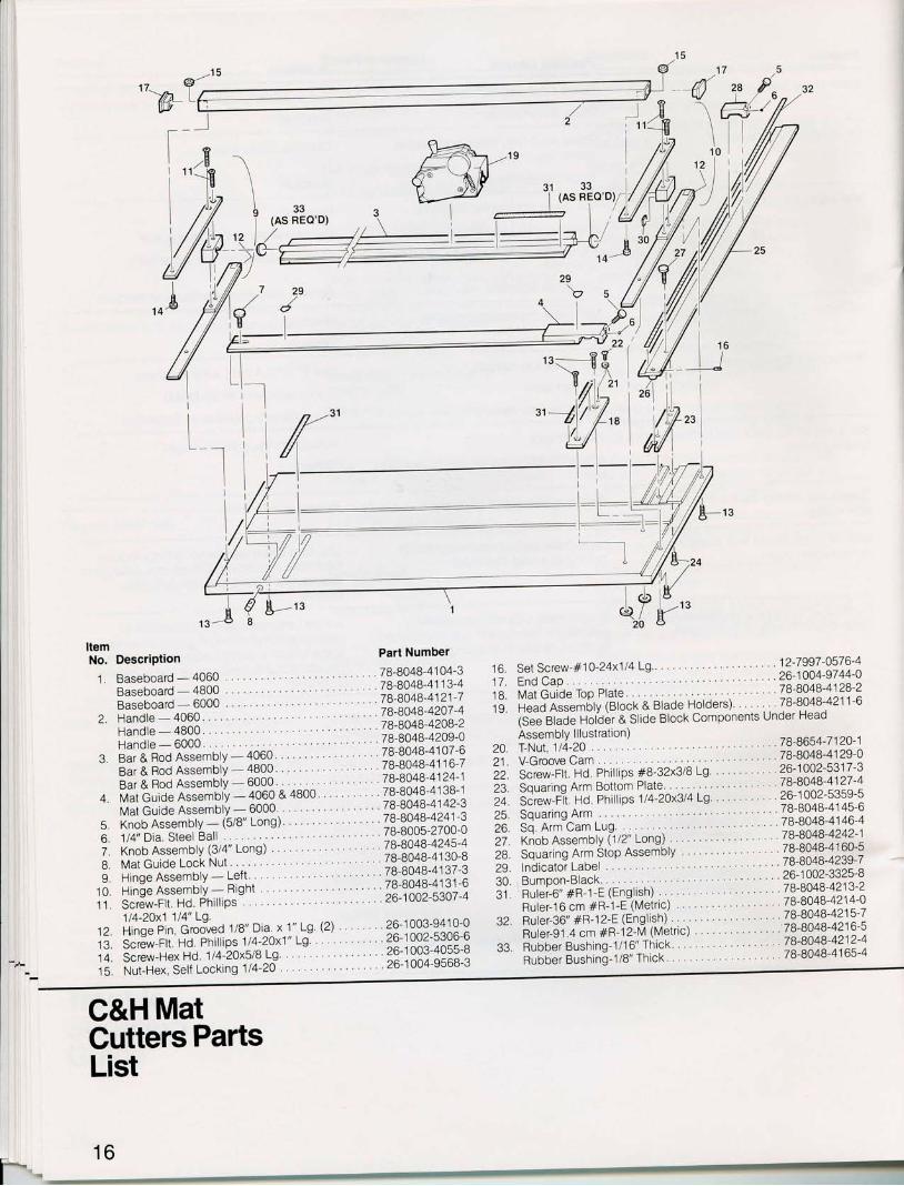
Set Screw-#10-24x114 Lg . . 12-7997-0576-4
End Cap " 26-1004-9744-0
Mat Guide Top Plate '78-Bo4B-4128'2i jJ"Jnt*t5ry (slock & Blade Holders) 78-8048-4211-6
is"lar;i" i;r'oJi a srloe Block components Under HeadAssembly l l lustrat ion) i6 6^-, 1t .A IT-Nut,1/4-20
71-8654-t lzu- l
V-Groovecam. " 78-Bo4B-4129-0
icru*-rrt no Phillips #8-32x3/B Ls ?9!99?21:\1Squaring Arm Bottom Plate ' t6-6u+o-+ tzt -+
sJi* r i t Hd. Phi l l ips 1t4-2Ox3t4 Lg ?9 1002-53s9-5SquaringArm.. . ' 78-8048-4145-6
Sq. Arm Cam Lug. 78-8048-4146-4
lioo nr.#ory (ilz" rong) 78-8048-4242'1s'qr"ti.g Att Stbp nsseriotv 78-8048-4160-5lndicator Label .. . " 78-8048-4239-7
Bumpon-Black 26-1002-3325-8nri"[0" +in-r r (English)nr i"oio.r +n- i -e iveir ic) 78-8048 4214 0
iir ir. io" +n-r 2-E iEnglish)' 78 8048-4215-7
nri"ngi.a "* #R-i2-M (Metric) 19 19124.7122
Rubber Bushing-1/ '16" Thick /6-6u46-4zt ' -+
R;bb;r eusnin6 l la" Thick . '78-8048-4165'4
o,,,,W
Description
Baseboard-4060..Baseboard - 4800 .Baseboard-6000..Handle-4060. . .Handle-4800,. . .Handle-6000., . . .
b-
ItemNo.
1.
Part Number
. 7B-8048-41 04-3
.78-BO4B-4113-4
.78'8048-4121-778-8048-4207'47a-A1LR-42C|R-2
to.17.1BIY
Bar & Rod AssemblY - 4060 'Bar & Rod AssemblY - 4800 'Bar & Rod AssemblY - 6000 ' 'Mat Guide AssemblY - 4060 & 4800'Mat Guide AssemblY - 6000 '
5. Knob Assembly - (5/B' Long)6. 114' Dia. Steel Bal l .7. Knob Assembly (3/4" Long)B. Mat Guide Lock Nut9. Hinqe AssemblY - Left
10. Hinge AssemblY - Right11. Screw-Fl t . Hd. Phi l l iPs
114-20x1 114" Lg.
. , 78-8048-4209-0
. . 78-8048-4107-6
. .78-8048-4116-7
. . 78-8048-4124-1.78-8048-4138-1
. .78'8048-4142-3
. .78-8048-4241-3
. . 78-8005-2700-0
. .78-8048'4245'4
. 7B-8048-4130-B
. .78-8048-4137-3
. . 78-8048-41 31 -6.26-1002'5307'4
20.zl ,
22.23.24.25.26.27.28.29.30.Jt.
32.
33.ta.
tJ.1A
tc
Hinqe Pin, Grooved 1i8" Dia x 1" Lg
Scr6w-Flt Hd. Phi l l ips 1t4'2Ox1" Lg
Screw-Hex Hd. 1/4-20x5l8 LgNut-Hex, Self Locking 114-20 " "
26-1 003-94 1 0-026-1 002-5306-626-'1003-4055-B26-.1004-9568-3
I
f - -IB
, 'E
\ to.8lo'orI (A5 HEIJ U, l
l , /l . /
-7tt.l.
-)\ / - \ . - i - )r: / :
= v22 l
,r<--88 I3a;\*'',
"_t),(,/,,lry\_l_l_
C&H MatGutters Parts
F.-
List
I/ l
I
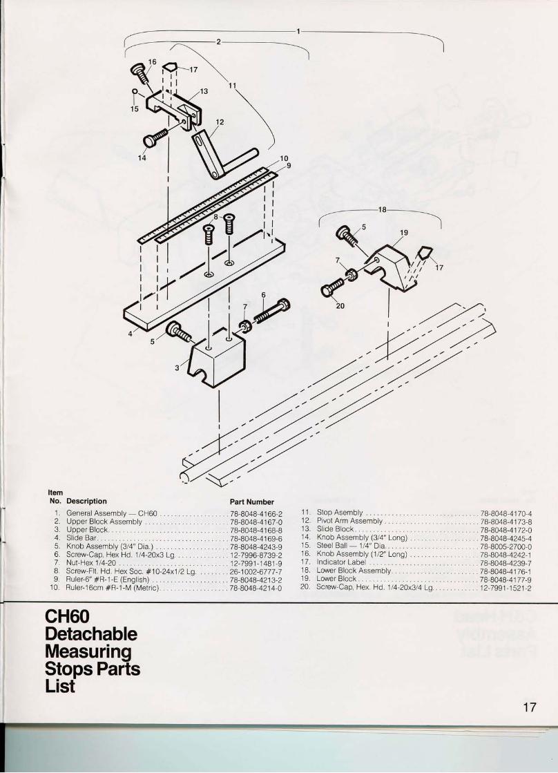
Descriptionl . General Assembly - CH602, UpperBlockAssembly . , . . .3. Upper Block. . .4. Sl ide Bar. . . ,5. Knob Assembly pla" Dia.)6. Screw-Cap, Hex Hd. 114-20x3 Lg. . . . ,7. Nut-Hex 114-20 .B, Screw-Fl t . Hd. Hex Soc, #.10-24x1 12Lg. , . . . . . .9. Ruler-6" #R-1-E (English)
10. Ruler-16cm #R-.1- lV (Metr ic) .
,-------...----.---------------.---------..,
Part Number
.78-8048-4166-2
.78-8048-4167-0
. 78-8048-41 6B-B78-8048-41 69-6
.7B-BO4B-4243-9
.12-7996-8739-2
.12-7991-1481-9
.26-1002-6777-7
.78-8048-4213-2
.78-8048-4214-0
'r- A
iII
f'
ItemNo.
11, StopAsembly . . . . . . .78-BO4B-41T0-412. PivotArmAssembly. . , . . . . . . . . . . . . . .78-8048-4173-813, Sl ide Block. . 7B-BO4B-4|72-O14. Knob Assembly (3/4" Long) . . .78-BO4B-4245-415. SteelBal l -1 l4"Dia. . . . . , . , . .78-8005-2700-016. Knob Assembly (1/2" Long) . . .7B-BO4B-4242-117. lndicator Label . . . . . .78-BO4B-4239-718. LowerBlockAssembly. . . . . . . .78-8048-4176-119. LowerBlock. . . . . . . . . t8-BO4B-4177-g20. Screw-Cap, Hex. Hd. 114-20x3t4 Lg.. . . . . . . . . . . .12-7991-1521-2
0,9
cH60DetachableMeasurinqStops PaitsList
17
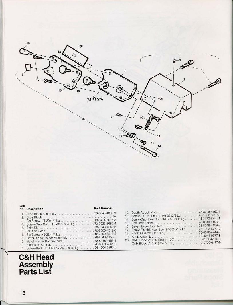
ItemNo. Description
Sl ide BlockSl ide Block Assembly
Part Number
7B-BO4B-4002-9
1- \
. . . . .78-8048-4162-1
. . . . .26-1002-5310-8
. . . . .18-3172-9215-1. , .78-8048-4158-9
. . . .78-8048-4159-7
. . . . .26-1002-6777-7. ..78-8048-4244-7
. . . . .78-8044-0377-8
. . . . .70-0700-6176-0
. , . . .70-0700-6177-B
1.2.3,4.5.6.7,B.L
10.11.
Set Screw 114-20x1 14 Lg.. . , . .Screw-Cap, Soc. HD. #B-32x5lBLg. . . .Shim KitCaution Decal . .Set Screw #B-32x114 Lg.. . . , .Bevd Blade HolderAssembly . . . . . . .Bevel Holder Bottom PlateExtension Spring.Screw-Rnd. Hd. Phi l l ips #6-32x3/B Lg..
. . . , . . . 1 8-341 4-501 6-3
. . . . . . . 70-7023-3680-4. . 78-8048-4240-5, . . .70-8000-4519-0
. . . . . . . 12-7999-581 7-3
. . . . . . . 78-8048-4155-5
. . . , . . . 78-8048-4157-1
. . . . . , . 78-8003-7861-0
. . . . .26-1004-7285-6
12. Depth Adjust. Plate.13, Screw-Flt. Hd. Phi l l ips #6-32x3l9 Lg. . .14. Screw-Cap, Hex. Soc. Hd. #B-32x1" Lg..15. Shoulder Screw . ,16. Bevel Holder ToP Plate. . .17. Screw-Flt. Hd. Hex. Soc. #10-24x112L9 .18. Knob AssemblY (1" Dia.)19. Knob AssemblY.20. C&H Blade #1200 (Box of 100)
C&H Blade #1500 (Box of 100)
,NA
C&H HeadAssemblyParts List
18
6
. iP,ql&?'' 24
%19
vI
-q,,''u5
(AS REO'D)
I
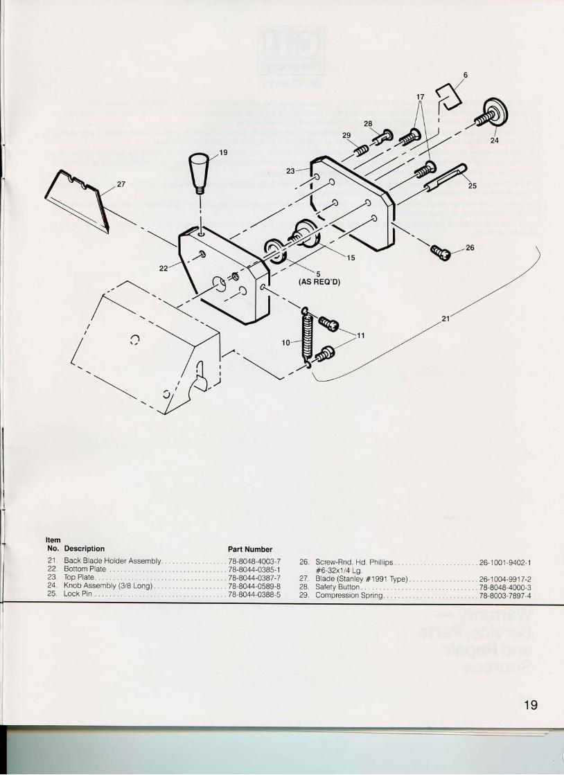
ItemNo.zt.
2223.2425.
Back Blade Holder AssemblvBottom PlateTop Plate.KnobAssembly(3iB Long) . . . . . . . . .Lock Pin
Part Number
.78-8048-4003-7
. 7B-8044-0385-1
.78-8044-0387-77B-8044-0589-B78-8044-0388-5
Screw-Rnd. Hd, Phi l l ips. . . .#6-32x114 Lg.Blade (Stanley #1991 Type)Safety ButtonCompression Spr ing. . . , . .
26-1004-9917-27B-8048-4000-378-8003-7897-4
WARRANTY
Nielsen and Bainbridge warrants new C&H/BAINBRIDGE cutters, accessories and parts to be free from defects in material andworkmanship for a period of ninety (90) days from the date of purchase by the original user/consumer. Each cutte[ accessory and partwil l be thoroughly inspected before shipment to insure conformance to specifications.lf a C&H cutter, accessory or part malfunctions or is inoperable within the warranty period because of a defect in material or workmanship,we wil l repair, or at our option, replace the defective unit at no cost to the original user or consumer purchaser.
This warranty excludes and does not cover defects or malfunctions of a cutter, accessories or parts due to repairs by persons not authorizedby us; by use of parts or accessories not designed or authorlzed by us; by mishandling, improper adjustment, modifications or damages.To obtain repair or replacement under this warranty, contact your C&H distributor.This warranty is in l ieu of all other warranties expressed or implied. Nielsen & Bainbridge expressly disclaims all other warranties, includingthe warranties of merchantabil ity and fitness for a particular purpose.The manufacturer neither assumes nor authorizes any representative or other person to assume for it, any other l iabil i ty in connection withthe sale. maintenance, or repair of cutters.In no event shall Nielsen & Bainbridge be l iable for any damages or losses, incidental or consequential, direct or indirect, arising out of theuse of this product.
Warrantv -Service,?artsand RepairSources
20
CHANGE NO. 1
CHANGE NO. 2
CHANGE NO. 3
CHANGE NO. 4
REVISIONS December 1985
C&HMatCutterOperating Manual & Parts List
Several major components of the C & H Mat Cutters have beenmodified and improved. This information sheet is intended to pointout these changes, properly describe them and specify any in-structional changes in this manual.
Page 2, Description of Cutter Parts; No. 1, Bar & Rod Assemblyshould read:
Bar/Rod-This component has a hard finish and a self-lubricating coating. The bar/rod has a deliberate bow whichcreates a uniform clamping force when handle pressure is ap-plied. The bar/rod also provides a precision tracking surfacefor the sliding block.Call-out should also read - 1-bar/rod
Page 2, Description of Cutter Parts, No. 4, Bevel Blade Holdershould read:
An adjustable, precision metal alloy assembly. Mounts andpivots on the bevel side of the sliding block. Designed forC & H No. 1200 and No. 1500 blades.
Page 3, Description of Cutter Parts, No. 15, Straight Side BladeHolder should read:
Straight Side Blade Holder-An adjustable, precision metal alloyassembly. Mounts and pivots on the right side of the sliding block.Designed for Stanley No. 1991 blade or equivalent.
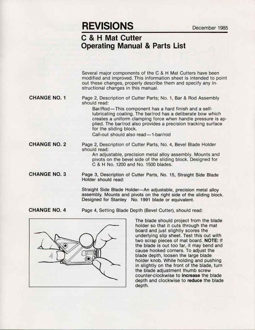
Page 4, Setting Blade Depth (Bevel Cutter), should read:
The blade should project from the bladeholder so that it cuts through the matboard and just slightly scores theunderlying slip sheet. Test this out withtwo scrap pieces of mat board. NOTE: lfthe blade is out too far, it may bend andcause hooked corners. To adjust theblade depth, loosen the large bladeholder knob. While holding and pushingin slightly on the front of the blade, turnthe blade adjustment thumb screwcounter-clockwise to increase the bladedepth and clockwise to reduce the bladedepth.
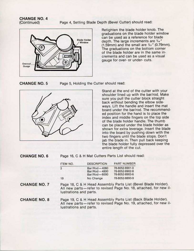
Retighten the blade holder knob. Thegraduations on the blade holder windowcan be used as a reference for bladedepth. The large increments are %0"(1.59mm) and the small are'/s"" (0.79mm).The graduations on the bottom cornerof the blade holder are in the same in'crements and can be used as a visualgauge for over- or under- cuts.
Cutter should read:
Stand at the end of the cutter with yourshoulder l ined up with the bar/rod. Makesure you pull the cutter block straightback without bending the elbow side-ways. Lift the handle and insert the matboard under the bar/rod. The recommend'ed position for the hand is to place theindex and middle fingers on the top sideof the blade holder handle. The thumbcan be placed under the blade holder asshown for extra leverage. Insert the bladeinto the board by pushing down with thetwo fingers unti l the blade stops. Don'tjab the blade in. Then pull back keepingthe blade holder fully depressed over theentire length of the cut.
Cutters Parts List should read:
CHANGE NO. 4(Continued)
CHANGE NO. 5 Page 5, Holding the
CHANGE NO. 6 Page16,C&HMat
CHANGE NO. 7
CHANGE NO. 8
Page 4, Setting Blade Depth (Bevel Cutter) should read:
ITEM NO. DESCRIPTION PART NUMBER
3 Bar/Rod-4060 78-8052-8901-0Bar/Rod-4800 78-8052'8902-8Bar/Rod-6000 78-8052-8903-6
19 No Change 78-8052-8893-9
Page 18, C & H Head Assembly Parts List (Bevel Blade Holder).Al l new parts-referto revised Page No. 18, at tached, for new i l 'lustrations and parts.
Page 19, C & H Head Assembly Parts List (Back Blade Holder).Al l new parts-refer to revised Page No. 19, at tached, for new i l -lustrat ions and parts.
C&H Mat Cutters Parts List
-J
At
{ '
I
t1l
t_l-l -L-_t-l
{
ItemNo. Description Parl Number
ItemNo. Description Part Number
1. Baseboard-4060 . . . . .78-8048-4104-3Baseboard-48O0 . . . . .78-8048-41 13-4Baseboard-6000 .. . . .78-8048-4'121-7
2. Handle-4060 .. . . . . . .78-8048-4207'4Handle-4800 .78-8048-4208-2Handle-6000 .78-8048-4209-0
3. Bar/Rod-4060 . . . . . . .78-8052-8901-0Bar/Rod-4800.. . . . . .78-8052-8902-8Bar/Rod-6000.. . . . . .78-8052-8903-6
4. Mat GuideAssembly-4060 &4800. . . . .78-8048-4138-1MatGuideAssembly-6000.. . .78-8048-4142'3
5. Knob Assembly-(5/a" Long) . . . .78-8048'4241'36. 1/q" Dia. Steel Bal l . . . . .78-8005-2700-07. KnobAssembly(/q"Long) . . . . .78-8048-4245-48. Mat Guide Lock Nut . . . .78-8048-4130-89. HingeAssembly-Left . . . . . . . .78-8048-4137-3
10. HingeAssembly-Right. . . . . . .78-8048-4131-611. Screw-Flt. Hd. Phi l l ips . .26-1002-5307-4
1/q-2Qx1 t/q" Lg.12. Hinge Pin. Grooved ' /s" Dia. x 1 " Lg. (2) . .26-1003-9410-013. Screw-Flt. Hd. Phi l l ips t /q-20x1" L9 . . . . .26-1002-5306-614. Screw-HexHd.t /a-2ox5hLg . . . . .26-1003-4055-815. Nut-Hex. Self Locking Va-20 . . . .26-1004-9568-3
16. SetScrew-#10-24x1/4 L9.. . . . . . .12'7997-0576'417. EndCap.. . . . . .26-1004-9744'018. Mat Guide Top Plate . . .78-8048'4128'219. Head Assembly (Block & Blade Holders) . 78-8052-8893'9
(See Blade Holder & Sl ide Block ComponentsUnder Head Assembly l l lustrat ion)T-Nut, %-20 .. . .78'8654-7120-1V-GrooveCam.. . . . . . . .78-8048-4129-0Screw-Flt. Hd. Phi l l ips #8-32x3/a Lg. . , . . .26-1002'5317-3Squaring Arm Bottom Plate . . . .78-8048'4127'4Screw-Flt. Hd. Phi l l ips l /a-20x3/q Lg.. . . . .26-1002-5359-5SquaringArm.. . . . . . . .78'8048'4145'6Sq. Arm Cam Lug. . . . . .78-8048-4146-4KnobAssembly(t/2" tong) . . . . .78'8048-4242-1Squaring Arm Stop Assembly . . .78-8048-4160'5lndicatorLabel . . . . . . . .78-8048'4239'7Bumpon-Black. . . . . . . .26-1002'3325-8Ruler-6"#R-1-E(Engl ish). . . . . . .78-8048-4213'2Ruler-16cm#R-1-E(Metr ic) . . . . .78-8048'4214'0Ruler-36"#R-12-E(Engl ish) . . . . .78-8048'4215'7Ruler-91.4cm#R-12-M(Metr ic) . .78-8048'4216-5RubberBushing-%0"Thick . . . . .78-8048'42'12-4RubberBushing-7e"Thick. . . . . .78-8048'4165-4
20.21.22.23.z+-25.26.27.28.29.30.31.
32.
33.
\I
l l,(l i l
)ff"

Revised Page 18
I temNo. Descripl ion Parl Number
1. Sl ideBlockAss'y . . . . . .78-8052-8892-12. Sl ide Block . . . . . .N/A3. SetScrew t /a-Z0xr/n Lg. . . . . . . . .18-3414-5016-34. Screw-CapSoc. Hd. #8-32xu/aLg. . . . . . . .70-7023-3680-45. Spr ing Pin5/sz Dia.xZuLg. . . . . . .26-1000-2720-56. BevelBladeHolderAssembly . .78-8052-8891-37. ShimKit . . . . . .78-8048-4240-58. Caut ion Decal . . . . . . . . .70-8000-4519-09. Bevel Holder Bottom Plate .. . . .78-8052-8850-9
10. TorsionSpring. . . . . . . .78-8052-8879-8
nA"Ki\&
Part Number
11. Dowel Pin3/ 'e Dia.xt / t Lg. . . . . . .12-7996-6730-312. Nut-BladeAdjust . . . . . . .78-8052-8874-913. O-Ring l /q l .D. . .12-7995-5848-o14. Thumb Screen-Blade Adjust. . . .78-8052-8875-615. ShoulderScrew.. . . . . .78-8048-4158-916. Bevel HolderTop Plate . . . . . . . .78-8052-8861-017. Screen-Flt. Hd. Hex. Soc. #10-24xt/z Lg. .26-1002-6777-718. KnobAssembly(3/4" Dia.x1lz" LS.). . . . . . .78-8052-8789-919. C&H Blade #1 200 (Box of 100) . . . 70-0700-61 76-0
C&H Blade #1500 (Box of 100) . . . 70-0700-6177-8
I temNo. Descript ion
7(As REO'D) /
Revised Page 19
l lemNo. Descript ion
: \ - . -
>_rc
,/ ,\)J.)
20. Back Blade Holder Assembly . . .78-8052-8899-62'1. TorsionSpring. . . . . . . .78-8052-8880-022. Bottom Plate. . .78-8052-8867-323. Top Plate. . . . . .78-8052-8868-124. Knob Assembly (% LS) . .78-8044-0589-825. Lock Pin . . . . . .78-8052-8873-1
Part Number
'b,Y<
l lemNo. Description
26. Conical Spring . 78-8052-8894-727. RetainingRing.145l .D.. . . . . . . .78-8656-4001-128. SafetyButton. .78-8048-4000-329. Gompression Spring . . .78-8003-7897-430. Blade (Stanley #1991 Type) . . . . .26-1004-9917-2
Part Number
Lilho in U.S.A. with 3M Otfset Plates, Film and Proofing Systems.