Embed Size (px)
Citation preview

Tel: (905) 624-6499Fax: (905) 624-0228www.weconsystems.com
CHAIN CONVEYOR OWNERS MANUAL

Table of Contents
INTRODUCTION ............................................................................................................................ 3
SAFETY WARNINGS ..................................................................................................................... 5
BEFORE STARTING MAINTENANCE ...................................................................................................... 5 DURING MAINTENANCE ......................................................................................................................... 5 AFTER MAINTENANCE ............................................................................................................................ 5
EQUIPMENT DESCRIPTION ....................................................................................................... 7
EQUIPMENT DESCRIPTION ..................................................................................................................... 7
INSTALLATION INSTRUCTIONS ..............................................................................................10
POSITION AND ALIGNMENT ................................................................................................................. 10 CONVEYOR INSTALLATION ................................................................................................................. 11 SUPPORT ASSEMBLY ............................................................................................................................. 11 PREPARING UNIT TO RUN ..................................................................................................................... 12 CHAIN CONVEYOR OPERATION........................................................................................................... 12 CARRYING CHAIN ADJUSTMENT ........................................................................................................ 12
MAINTENANCE ............................................................................................................................13
MECHANICAL MAINTENANCE ............................................................................................................. 13 ELECTRICAL MAINTENANCE ............................................................................................................... 14
TROUBLE SHOOTING GUIDES .................................................................................................15
MOTOR AND GEAR REDUCER .............................................................................................................. 15 CHAIN AND SPROCKETS ....................................................................................................................... 15 ELECTRICAL ............................................................................................................................................ 16
PARTS GUIDE ...............................................................................................................................17
DRIVE TRAIN COMPONENTS ................................................................................................................ 17 MOTOR & REDUCER DRIVE COMBINATIONS .................................................................................... 17 SUPPORTS ................................................................................................................................................ 17 CARRYING CHAIN & ASSOCIATED COMPONENTS ........................................................................... 18 TOUCH-UP PAINT.................................................................................................................................... 18

W E C O N S Y S T E M S C H A I N C O N V E Y O R
M A N U A L
OM-CC-002 2 VERSION 1
www.weconsystems.com
THIS PAGE LEFT BLANK INTENTIONALLY

W E C O N S Y S T E M S C H A I N C O N V E Y O R
M A N U A L
OM-CC-002 3 VERSION 1
www.weconsystems.com
CHAIN CONVEYOR
HEAVY DUTY INDUSTRIAL CONVEYORS
INTRODUCTION
Thank you for purchasing a Chain Conveyor from Wecon Systems.
This model is made of the finest materials available and is
manufactured in Canada by skilled craftsmen. The conveyor is very
easy to operate and to maintain, but we recommend that you read this
owner's manual thoroughly before using the conveyor.
This manual provides installation instructions, start–up procedures,
safety tips, a parts list and information regarding preventative
maintenance, lubrication and troubleshooting. This conveyor is
durable and has been designed for a long service life.

W E C O N S Y S T E M S C H A I N C O N V E Y O R
M A N U A L
OM-CC-002 4 VERSION 1
www.weconsystems.com
THIS PAGE LEFT BLANK INTENTIONALLY

W E C O N S Y S T E M S C H A I N C O N V E Y O R
M A N U A L
OM-CC-002 5 VERSION 1
www.weconsystems.com
SAFETY WARNINGS
WARNING: DO NOT ATTEMPT MAINTENANCE ON ANY CONVEYOR WHILE IT IS IN OPERATION.
BEFORE STARTING MAINTENANCE
Read and understand instruction manual and be aware of all warning stickers. Know where the emergency stop buttons are located. Know or have quick access to emergency telephone numbers in the unforeseen
event that an emergency should arise. Maintenance functions are to be performed while the conveyor is off. The main
power disconnect switch to the conveyor shall be locked out in accordance with proper written lockout procedures. This will prevent anyone from applying power to the system while maintenance personnel are at work.
NEVER work on a conveyor while it is running unless the maintenance procedure requires the equipment to be running. When a conveyor must be operating to perform the maintenance, allow only properly trained maintenance personnel to work on the conveyor.
Wear safety glasses when in the proximity of the conveyor. NEVER allow personnel with long hair near the conveyor without the use of a
protective hair net.
DURING MAINTENANCE
Do not wear loose clothing, ties or jewelry while servicing or performing maintenance on any conveyor equipment.
Be aware of hazardous conditions, such as sharp edges and protruding parts. When using hoists, cables or other mechanical equipment to perform
maintenance, use care to not damage conveyor components. Keep area clean. Clean up lubricants and other materials before starting
conveyor.
AFTER MAINTENANCE
Before starting the conveyor after any maintenance has been completed, walk around the equipment and make certain all safety devices and guards are in place, pick up tools, maintenance equipment and clear any foreign objects from equipment.
Make certain all personnel are clear of the conveyor and made aware that the conveyor is about to be started.
Only authorized personnel should be permitted to start any conveyor following maintenance or emergency shut-off.
Never place any part of your body in or on any part of this conveyor while in operation.
Do not allow anyone to stand on the conveyor. Do not allow horseplay around the conveyor. Do not remove guards, perform maintenance or clear obstructions without
first locking out the main power disconnect switch.

W E C O N S Y S T E M S C H A I N C O N V E Y O R
M A N U A L
OM-CC-002 6 VERSION 1
www.weconsystems.com
PLEASE RECOGNIZE ALL WARNING STICKERS AND OBEY ANY SAFETY INSTRUCTIONS. WARNING STICKERS ARE PLACED ON THE EQUIPMENT FOR YOUR SAFETY – PLEASE DO NOT REMOVE THEM. CONDITIONS DO EXIST ON ANY CONVEYOR THAT CAN CAUSE INJURY OR DEATH TO PERSONNEL. NO MANUAL CAN COVER ALL THE HAZARDOUS CONDITIONS THAT MIGHT DEVELOP. ALL PERSONNEL INVOLVED IN THE OPERATION OF ANY CONVEYOR EQUIPMENT SHOULD BE CONSTANTLY AWARE OF ANY UNSAFE CONDITIONS AND USE ALL POSSIBLE CARE, ALONG WITH COMMON SENSE AND STRICT ADHERENCE TO ACCEPTED SAFETY STANDARDS TO AVOID INJURY.
3-STRAND CHAIN CONVEYOR WITH OPTIONAL SIDE MOUNTED DRIVE
IMPORTANT
Wecon Systems does not warrant parts or components not manufactured by Wecon Systems. The manufacturers of electric motors and controls, air and hydraulic components and certain other items extend warranties, which may or may not be similar to that of Wecon Systems manufactured equipment. Defective material of this type should be reported by the customer to Wecon Systems whose sole responsibility is to notify the vendor of the defective material for action. Wecon Systems will not be responsible for units that have been tampered with or disassembled by anyone other than the authorized representative of the respective manufacturer.

W E C O N S Y S T E M S C H A I N C O N V E Y O R
M A N U A L
OM-CC-002 7 VERSION 1
www.weconsystems.com
EQUIPMENT DESCRIPTION
EQUIPMENT DESCRIPTION
Chain conveyors operate using a series two or more strands of carrying chain that are powered to move the product. They are ideally suited to convey products (pallets or goods exhibiting a uniform, rigid bottom) easily along the surface of the chain. Power for the series of carrying chains is provided by a common drive shaft arrangement. All beds are fabricated using heavy-duty construction within a steel frame. Depending on application or load rating, each strand of carrying chain is structurally supported by a UHMW track or steel wear bar that guides the chain along the length of the conveyor. For applications utilizing the UHMW wear strip, the wearstrip provides quiet operation, wear resistance and reduces horsepower requirements. Those applications utilizing steel wear bars are typically designed for higher load ratings. Chain conveyors are capable of indexing or two-way applications depending on the type of drive used. Heavy-duty construction makes these conveyors ideally suited for harsher environments where dirt, grease, heat, oil and other contaminants are present. Chain conveyors provide smooth, continuous flow of product under positive control. They are designed to transport the product along a horizontal plane. Wecon chain conveyors are available in different drive configurations. End drives are standard, with the drive mounted below and within the bed frame. Drives mounted outside the bed frame are available as an option. Centre drives are available as an option but offer the capability of one-way or two-way operation. End drives are capable of one-way operation only. Chain conveyors are available with carrying chains on varying centers. Determination of the required number of chain strands is dependant on many parameters including width, weight and deflection of the carrying surface of the product being transported. Typically, the more uniform the transporting surface, the greater the allowance for larger carrying chain centers. Conveyor frames are heavy-duty welded construction consisting of 6” x 2” x 3/16” wall HSS tube side channels, with a series of 3” x 1-1/2” x 1/8” wall HSS tube cross members welded in place along the side channels. For end drive configurations, one end of each side channel is coped to accept a flange bearing and drive shaft arrangement making it an integral part of the design. The opposite ends of each side channel are coped to accept an idler sprocket arrangement. The carrying chains are installed and run along either a UHMW guide track or steel wear bar arrangement (depending on application) that is installed on the top of the side channels. Various accessories and options are available including multiple chain strands, limit switches, proximity switches, photo eyes, and guard rails.

W E C O N S Y S T E M S C H A I N C O N V E Y O R
M A N U A L
OM-CC-002 8 VERSION 1
www.weconsystems.com
Drive – Is the power source that moves the chain. End drives are standard, with the drive
mounted below and within the bed frame. Drives mounted outside the bed frame are available as an option. Standard drives have fixed speeds. All are capable of indexing. Optional centre drives are available but offer the capability of one-way or two-way operation. For two-way operation, the drive must be located as close as possible to the center of the bed length, midway between each end. This makes for roughly equal runs of chain to each side of the drive, keeping the required chain pull to a minimum. End drives are capable of one-way operation only.
Carrying Chains – Provides a surface to carry the product.
Consists of heavy duty riveted double pitch chain C2060 or C2080 depending on the required load capacity. The double pitch conveyor chains reduce product damage and wear when compared to standard roller chain.
1. C2060 double pitch conveyor chain is used to accommodate a maximum unit load of
2000 lbs. For end drive configurations, the carrying chain is drawn along a length of UHMW guide track or steel wear bar (depending on application and load) and over a C2060A idler sprocket at the end of the conveyor. The chain is re-routed back and over the drive sprocket to form an endless loop.
2. C2080 double pitch conveyor chain is used to accommodate a maximum unit load of
4000 lbs. For end drive configurations, the carrying chain is drawn along a length of UHMW guide track or steel wear bar (depending on application and load) and over a C2080A idler sprocket at the end of the conveyor. The chain is re-routed back and over the drive sprocket to form an endless loop.
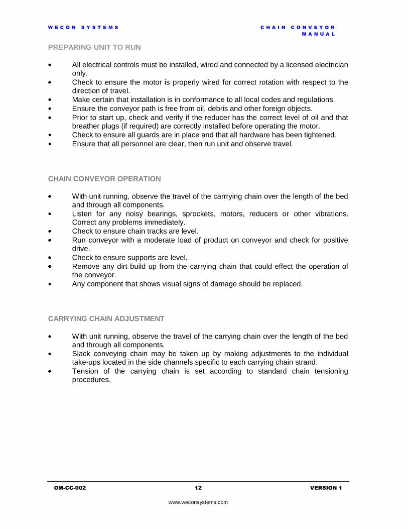
TYPICAL IDLER SPROCKET ARRANGEMENT SHOWING CARRYING CHAIN

W E C O N S Y S T E M S C H A I N C O N V E Y O R
M A N U A L
OM-CC-002 9 VERSION 1
www.weconsystems.com
Heavy Duty Supports – Must be mounted to the floor. All heavy duty supports are fully
adjustable for final set up and leveling. Numerous width and height combinations are available.
HEAVY DUTY SUPPORT

W E C O N S Y S T E M S C H A I N C O N V E Y O R
M A N U A L
OM-CC-002 10 VERSION 1
www.weconsystems.com
INSTALLATION INSTRUCTIONS
POSITION AND ALIGNMENT
Proper mechanical installation is vital for the equipment to operate as described. Our installation standards show the importance that Wecon places on a quality installation.
Installation Standards
In General: The following standards, where applicable, will be used as guidelines by Wecon approved installers.
Dimensional Reference Points: The location of each conveyor in the system will be determined by establishing a reference point to the center of each conveyor from the fixed building column lines as indicated on approved general arrangement drawings.
Level and Elevations: Conveyors will be installed in accordance with the elevations shown on the layout drawing(s). After the first elevation is established, the elevation of all other points will be related to this first point. The practice of dimensioning elevations from the floor at each point of support will not be followed. When the floor level changes significantly, such as the system going to an upper or lower floor, or into another building or room, a new elevation will be established from the first floor at that point. This new elevation will then become the reference point for subsequent elevations.
Standards For Floor Mounting: Anchoring will be accomplished by drilling into the floor and inserting a suitable anchor bolt in an approved manner in accordance with the manufacturer’s instructions. Drive and intermediate stands will be anchored with 3/8” diameter minimum bolts, one in each leg. Explosive type anchors will not be used. Adhesive or specialized anchors will be used only when specified.

W E C O N S Y S T E M S C H A I N C O N V E Y O R
M A N U A L
OM-CC-002 11 VERSION 1
www.weconsystems.com
CONVEYOR INSTALLATION
It is recommended that only trained personnel install or service this equipment.
Wecon chain conveyors are shipped on skids, generally, not exceeding 4000 pounds, for lift truck unloading and handling. The skids may also be handled with a crane if one is available. If a crane is utilized, ensure the operator is certified in the competency of its operation. Each skid will vary in width, length and height depending upon the style of product purchased.
The conveyor frames, supports, and accessories should be thoroughly inspected before proceeding with the conveyor installation. Upon delivery, be sure to check the following items very carefully:
The alignment of the frames, to ensure horizontal and parallel orientation.
The equipment to ensure there is no visible damage to the frames, supports or accessories.
Floor Mounted Units
At the desired position for the conveyor, snap a chalk line (not in excess of 100 feet per run) on the floor location for the centre line of the unit.
Use a plumb line to align the centre line of each conveyor section to the chalk line.
Set height of unit.
Adjust the conveyor both lengthwise and diagonally using a level.
NOTE: Beds must be level from side to side to prevent the possibility of skewing the product.
SUPPORT ASSEMBLY
Typically, a chain conveyor would be shipped with the supports installed on the conveyor. In the event the supports are shipped loose, the supports are fastened to the bottom web of the side channel utilizing holes designed into each bed section. For those applications, supports can be mounted in the first available set of holes at the charge and the discharge ends of the conveyor. Mounting a support can be accomplished by either lifting the bed section into position onto a support or attaching the support to a bed section prior to lifting it into position. After the conveyor has been aligned and leveled, anchor the supports to the floor in an approved manner in accordance with the anchor bolt manufacturer’s instructions.
HD SUPPORT MOUNTED AT THE END OF A CONVEYOR
W E C O N S Y S T E M S C H A I N C O N V E Y O R
M A N U A L
OM-CC-002 12 VERSION 1
www.weconsystems.com
PREPARING UNIT TO RUN
All electrical controls must be installed, wired and connected by a licensed electrician only.
Check to ensure the motor is properly wired for correct rotation with respect to the direction of travel.
Make certain that installation is in conformance to all local codes and regulations.
Ensure the conveyor path is free from oil, debris and other foreign objects.
Prior to start up, check and verify if the reducer has the correct level of oil and that breather plugs (if required) are correctly installed before operating the motor.
Check to ensure all guards are in place and that all hardware has been tightened.
Ensure that all personnel are clear, then run unit and observe travel.
CHAIN CONVEYOR OPERATION
With unit running, observe the travel of the carrrying chain over the length of the bed and through all components.
Listen for any noisy bearings, sprockets, motors, reducers or other vibrations. Correct any problems immediately.
Check to ensure chain tracks are level.
Run conveyor with a moderate load of product on conveyor and check for positive drive.
Check to ensure supports are level.
Remove any dirt build up from the carrying chain that could effect the operation of the conveyor.
Any component that shows visual signs of damage should be replaced.
CARRYING CHAIN ADJUSTMENT
With unit running, observe the travel of the carrying chain over the length of the bed and through all components.
Slack conveying chain may be taken up by making adjustments to the individual take-ups located in the side channels specific to each carrying chain strand.
Tension of the carrying chain is set according to standard chain tensioning procedures.

W E C O N S Y S T E M S C H A I N C O N V E Y O R
M A N U A L
OM-CC-002 13 VERSION 1
www.weconsystems.com
MAINTENANCE
WARNING: DO NOT ATTEMPT MAINTENANCE ON ANY CONVEYOR WHILE IT IS IN OPERATION.
MECHANICAL MAINTENANCE
Item Schedule Service Suggested Maintenance
Gear reducer At start-up and every month of operation
Check oil
Yearly Change oil
Motor At start-up and every month of operation
Check mounting hardware and align if necessary
Drive chain Monthly Check tension and alignment
Monthly Clean and lubricate with recommended oil using a brush or spray
Carrying chains Monthly Check tension and alignment
Monthly Clean and lubricate with recommended oil using a brush or spray
Protective guards At start-up and every week of operation
Check to ensure all guards are in place and properly secure
Supports Weekly Check to ensure supports have not been damaged and are properly secured
Hardware At start-up and every week of operation
Check to ensure all fasteners are in place and properly tightened
Note: Gear reduction drives units are filled with lubricant prior to shipping. The lubricant level should be checked prior to start-up and the breather plug installed in the proper location (see reducer manual supplied with unit). Only refill reducers with the approved lubricant required for standard service - if service is more severe; the oil should be changed more frequently. Consult the reducer manufacturer for a more specific lubrication schedule.

W E C O N S Y S T E M S C H A I N C O N V E Y O R
M A N U A L
OM-CC-002 14 VERSION 1
www.weconsystems.com
ELECTRICAL MAINTENANCE
WARNING: DISCONNECT ALL POWER BEFORE PERFORMING THE FOLLOWING MAINTENANCE. ENSURE THE MAIN POWER DISCONNECT SWITCH TO THE CONVEYOR IS LOCKED OUT IN ACCORDANCE WITH PROPER WRITTEN LOCKOUT PROCEDURES.
ONLY QUALIFIED PERSONNEL SHOULD PERFORM THE FOLLOWING MAINTENANCE.
Note: A qualified person should keep a logbook of the following readings noting and documenting any excessive changes from normal that could indicate a potential problem.
1. Measure voltages and current of incoming power to enclosure. 2. Measure current readings of all motors. 3. Measure current readings on primary and secondary of control transformer to
insure proper infeed and outfeed voltage. 4. Review usage - excessive use of fuses or replacing the same part several times
indicates an excessive current draw, faulty components, or exceeding the capacity of the conveyor unit.
Item Schedule Service Suggested Maintenance Control panels and pushbutton enclosures
Always Enclosures should be clean and dry
Weekly Check if components have vibrated loose, check door/power interlocks and latches
At start-up, monthly or if any problems occur
Check for loose or discolored wires (Discolored wires indicate an excessive current draw)
Photoeyes At start-up, weekly Dust, oil and foreign objects should be wiped from lenses and reflectors
Limit switches Weekly Check arms for adjustment and tightness
Pushbuttons Weekly Check wires and terminals for tightness
Emergency stop devices
Weekly Check for proper operation
Conduit and conduit hangers
Monthly Check for alignment and damage, exposed wiring
Wiring At start-up, monthly or if any problems occur
Check for exposed cords and wires for damage, replace as necessary

W E C O N S Y S T E M S C H A I N C O N V E Y O R
M A N U A L
OM-CC-002 15 VERSION 1
www.weconsystems.com
TROUBLE SHOOTING GUIDES
MOTOR AND GEAR REDUCER
Problem Possible Cause Suggested Solution
Hard to start, stalling out or running hot
Drag on conveyor Inspect for obstruction causing drag and remove
Lack of lubricant Check oil level in gearbox, verify vent breather plug is open
Overloaded Remove load and possibly increase horsepower
Electrical Check wiring, circuits and take load readings
Excessive noise Lack of lubricant Check oil level in reducer and add if required
Damaged gears Replace unit
Faulty bearing Replace bearing
CHAIN AND SPROCKETS
Problem Possible Cause Suggested Solution
Abnormal wear Excessive chain tension Reduce the chain tension
Misaligned sprockets Align sprocket faces using a straight edge and tighten set screws
Chain not lubricated Lubricate with proper lubricant
Damaged chain or sprocket
Replace damaged component
Misaligned chain guard Adjust as required
Excessive noise Loose chain Adjust chain tension
Chain not lubricated Lubricate with proper lubricant
Misaligned sprockets Align sprocket faces using a straight edge and tighten set screws
Pulsating chain Improper chain tension Adjust chain tension
Overloaded conveyor Inspect for obstruction causing drag or remove excess load
Broken chain Seized or sticking sprocket or shaft
Inspect and replace damaged items
Worn or damaged chain Replace damaged chain
Obstruction Inspect conveyor for obstruction and remove
Sprockets loose on shaft Loose set screws Align sprocket faces using a straight edge and tighten set screws
Worn or damaged key Replace key and inspect shaft keyway for damage
Chain slack Normal wear Adjust chain to proper tension or replace chain

W E C O N S Y S T E M S C H A I N C O N V E Y O R
M A N U A L
OM-CC-002 16 VERSION 1
www.weconsystems.com
ELECTRICAL
Problem Possible Cause Suggested Solution
Motor not operating Emergency stop activated
Reset pull cord, air pressure switch or pushbuttons
Blown fuses If resistance from hot to ground is OK replace fuse
Overload relay tripped Reset relay, measure current draw
Check for wiring problems
Check wiring diagram for correct connections
Unit running wrong direction
3 phase motor wired incorrectly
Check proper voltage wiring diagram
1 phase motor wired incorrectly
Check proper voltage wiring diagram
DC motor wired incorrectly
Check proper voltage wiring diagram
Overload relay trips Check setting on overload relay with full load amperage on motor nameplate
If incorrect, reset overload relay
Check for mechanical binding or jams
Remove item creating drag load on unit - check belt
Additional load is too much for motor
Decrease the amount of product load on unit
Check if motor current draw is high
Drive may require more horsepower-consult factory
Unit operates sporadically Check photoeyes Clean lenses and check for proper alignment
Check reflectors Clean and check for proper alignment
Limit switches Check arm location and tightness
Solenoids Check pressure at the valve
Loose connections Check wire nuts and terminal strip
DO NOT ATTEMPT MAINTENANCE ON ANY CONVEYOR WHILE IT IS IN OPERATION. DISCONNECT ALL POWER WHILE PERFORMING ANY MAINTENANCE FUNCTIONS ENSURING THAT THE MAIN POWER DISCONNECT SWITCH TO THE CONVEYOR IS LOCKED OUT IN ACCORDANCE WITH PROPER WRITTEN LOCKOUT PROCEDURES.

W E C O N S Y S T E M S C H A I N C O N V E Y O R
M A N U A L
OM-CC-002 17 VERSION 1
www.weconsystems.com
PARTS GUIDE
DRIVE TRAIN COMPONENTS
COMPONENT PART NUMBER
Driver sprocket - refer to order (reducer)
Specify series, hub type, number of teeth x bore from sprocket
Driven sprocket - refer to order (drive shaft)
Specify series, B type, number of teeth x bore from sprocket
RC 60 chain RC 60 x length
RC 60 connecting link RC-60-CL
RC 60 offset link RC-60-OL
2 hole flange brg x refer to order (common drive shaft)
Specify bore diameter
Drive Shaft – refer to order Specify shaft diameter, length, number and location of keyways
Driver sprockets – refer to order (common drive shaft – carrying chain)
Specify series, hub type, number of teeth x bore from sprocket
MOTOR & REDUCER DRIVE COMBINATIONS
COMPONENT PART NUMBER
Motor – refer to order Specify manufacturer, HP, voltage, enclosure, mtg from motor nameplate
Reducer – refer to order Specify manufacturer, style, size, ratio, handing, mtg from reducer nameplate
SUPPORTS
WHEN ORDERING SUPPORTS USE THE FOLLOWING FORMAT
F S 2 4 2 2 - 1 7 2 5 - X BLANK FOR STANDARD MODEL B.F.R. H FOR HEAVY DUTY M FOR MOBILE OVER ALL WIDTH MAX. SUPPORT HEIGHT MIN. SUPPORT HEIGHT

W E C O N S Y S T E M S C H A I N C O N V E Y O R
M A N U A L
OM-CC-002 18 VERSION 1
www.weconsystems.com
CARRYING CHAIN & ASSOCIATED COMPONENTS
COMPONENT PART NUMBER
C2060 chain - heavy duty riveted C2060H
C2060 connecting link - heavy duty C2060H/2062H-C/L
C2080 chain - heavy duty riveted C2080H
C2080 connecting link - heavy duty C2080H/2082H-C/L
UHMW chain guide track to suit C2060 chain x 10 ft long (cut to suit application)
HB-2060-10
UHMW chain guide track to suit C2080 chain x 10 ft long (cut to suit application)
HB-2080-10
Self tapping screw #8-32 UNC x 7/16” lg ST-565P
7/16”square steel wear bar to suit C2060 chain x specify length
FISTE0742025
1/2"square steel wear bar to suit C2080 chain x specify length
FISTE0742030
End idler sprocket 60A20 x 5/8" bore HN60A20X5/8
End idler sprocket 80A12 x 3/4" bore HN80A12X3/4
Take-up sprocket 60A13 x 5/8" bore HN60A13X5/8
TOUCH-UP PAINT
COLOUR PART NUMBER
Wecon (shop) blue P-S-BLUE
Ermanco blue (ER-1) P-E-BLUE-ER-1
Ermanco blue (ER-2) P-E-BLUE-ER-2
Medium grey P-M-GREY
Wecon (shop) green P-S-GREEN
Safety yellow P-S-YELLOW