Embed Size (px)
Citation preview
Prosthodontics
Chairside prefabricated fiber-reinforced resincomposite fixed partial denturesJonathan C. Meiers, DMD, MSVMartin A, Freilich, DDS^
The introduction ot pre-impregnated fiber-reinforcGd resin composites has provided the dental professionwith the opportunity to fabricate and deliver adhesive, esthetic, and metal-free tooth replacements.Utilizing this technology, a prefabricated (iber-reinforced resin composite fixed partial denture prototypethat allows rapid, cost-ett9otive, and noninvasive fixed tooth replacement for single anterior teeth has beendeveloped. Ideal situations tor this type of service include: a fixed replacement tollowing tooth loss tromtrauma; a fixed tooth replacement in medically compromised patients who cannot sit tor extended periodsof time or have local anesthesia; periodonlally compromised abutments; a fixed space maintainer followingorthodontic movement; and a fixed provisional during the post implant healing phase prior to loading. Thisarticle describes the framework construction and placement protocol for the pretabricated fiber-reinforoedresin composite fixed partial denture. (Quintessence int 2001:32:99-104)
Key words: direct fixed partial denture, fiber-reinforced resin composite, particulate resin composite
CLINICAL RELEVANCE: Prefabricated, fiber-reintorcedresin composite chairside fixed partial dentures offer anesthetic and potentiaily durable solution for cost-effective,noninvasive tooth replacement for many clinical situa-tions.
The advances in materials and techniqttes for adhe-sive dentistry have allowed the development of
noninvasive or miriimally invasive approaches forreplacing a missing anterior tooth in those clinical sit-uations where the adjacent abutment teeth have norestorations. These approaches have used acid-etched,adhesive resin-coated enamel with particulate com-posite alone or in conjunction with metal or fiber-reinforcement to attach a pontic.'-'^ The introductionof pre-impregnated fiber-reinforced composite (FRC)has provided another option for chairside fixed partialdenture (FPD) fabrication,"^-'̂ Previous articles have
'Associate Protessor, Division Head for Operative Dentistry, Department otProsttiodontics and Operative Dentistry, University of Connecticut Schoolot Dental Medicine, Farmington, Connecticut.
^Associate Protessor, Division Head tor Fixed Prosthodontics, Departmentot Prosthodontics and Operative Oentistry, University of ConnectrculSchool of Dental Medioine, Farmington, Connecticut.
Reprint requests: Dr Jonattian C. fuleiers, Department ot Prcsthodonticsand Operative Oentistry, University ot Connecticut Sctiool ot DentalMedicine, 263 Farmington Avenue, Farmington, Connecticut 06030-16t5.E'[email protected],edj
described chairside FPDs that used a denture tooth asa pontic with slots placed in the abutment teeth forstrips of pre-impregnated PRC to strengthen the pon-tic/abutment tooth connections,''^" The potential dis-advantages of the denture tooth pontic technique arethe need for tooth preparation and the inherent differ-ent chemistries between the particulate resin compos-ite/FKC and the denture teeth.
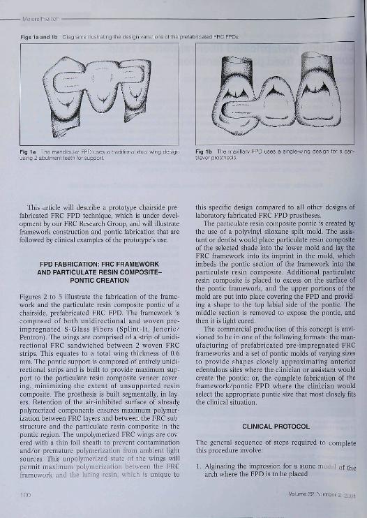
The ideal situation for chairside tooth replacementwould be a system where the clinician could select apre-formed pontic shape similar to the missing tooth.The pontic would have a framework attached to itallowing it to be rapidly piaced on the abutment teethwith iittle or no tooth reduction. The mechanical andphysical properties of pre-impregnated FRC have thepotential to allow the development of this type of toothreplacement system."'*- '̂ The chairside prefabricatedFRC FPD would be perfect for situations such as; theemergency replacement of a tooth lost to trauma orextracted due to failed endodontic, caries, or periodon-tal causes; a fixed space maintainer for adult or pédi-atrie situations after orthodontic treatment; patientswith abutments having questionable periodontal prog-nosis; patients who cannot tolerate local anesthesia orsit for extended periods of time due to medical reasons;and a fixed temporary footh replacement (in lieu ofnothing or a removable interim partial) for implantcases prior to loading the implant. Figures la and lbshow the two basic framework designs envisioned withthis FPD-the 2-wing abutment design and the moreconservative 1-wing, cantilever design.
Quintessence International 99
• Meiers/Freiiich
Figs la and Ib Diagrams iilustrating the design variations of the prefabricated FRC FPDs.
Fig 1a The mandibular FPD uses a traditionai duai-wing designusing 2 abutment teeih for support
Fig 1b The maxiilary PPD uses a single-wing design for a can-tilever prosthesis.
This atlicle will describe a prototype chairside pre-fabricated FRC FPD tecbnique, wbicb is under devel-opment by oitr FRC Research Group, and will illustrateframework construction and pontic fabrication that arefollowed by clinical examples of the prototype's use.
FPD FABRICATION: FRC FRAMEWORKAND PARTICULATE RESIN COMPOSITE-
PONTIC CREATION
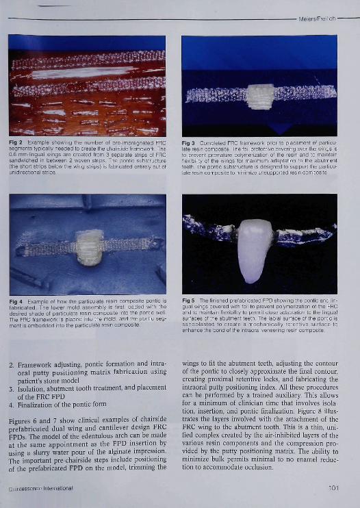
Figures 2 to 5 illustrate the fabrication of the frame-work and tbe particulate resin composite pontic of achairside, prefabricated FRC FPD, Tbe framework iscomposed of both unidirectional and woven pre-impregnated S-Glass Fihers (Splint-It, Jeneric/Pentron), Tbe wings are comprised of a strip of unidi-rectional FRC sandwicbed between 2 woven FRCstrips, Tbis equates to a total wing tbickness of 0,6mm, Tbe pontic support is composed of entirely unidi-rectional strips and is built to provide maximum sup-port to tbe particulate resin composite veneer cover-ing, minimizing the extent of unsupported resincomposite. The prosthesis is built segmentally, in lay-ers. Retention of tbe air-inbibited surface of alreadypolymerized components ensures maximum polymer-ization between FRC layers and between tbe FRC sub-structure and tbe particulate resin composite in thepontic region, Tbe unpolymerized FRC wings are cov-ered witb a tbin foil sbeath to prevent contatninationand/or premature polymerization from atnbient iightsources. Tbis unpolymerized state of the wings willpermit maximum polymerization between tbe FRCframework and the luting resin, which is unique to
this specific design compared to all other designs oflaboratory fabricated FRC FPD prostheses.
The particulate resin composite pontic is created bythe use of a polyvinyl siloxane split mold. The assis-tant or dentist wouid place particulate resin compositeof the selected shade into tbe lower mold and lay theFRC framework into its imprint in the moid, whicbimbeds tbe pontic section of the framework into theparticulate resin composite. Additional particulateresin composite is placed to excess on the surface ofthe pontic framework, and the upper portions of themold are put into place covering the FPD and provid-ing a shape to the top labial side of tbe pontic. Themiddie section is removed to expose the pontic, andthen it is light cured.
The commercial production of this concept is envi-sioned to he in one of the following formats: the man-ufacturing of prefabricated pre-impregnated FRCframeworks and a set of pontic molds of varying sizesto provide sbapes closeiy approximating anterioredentuious sites where the clinician or assistant wouldcreate tbe pontic; or, tbe complete fabrication of tbeframework/pontic FPD wbere tbe clinician wouldselect the appropriate pontic size that most closely fitsthe clinical situation.
CLINICAL PROTOCOL
The general sequence of steps required to completethis procedure involve:
1, Alginating the impression for a stonearch where tbe FPD is to be placed
of tbe
100 Volume 39, Number 2, 2ooi
Meiers/Freilich
Fig 2 Example showing ttie number ol pre-impregnated FRCsegments typically needed to create the chairside Iramework The0.6 mm-lingual wings are created from 3 separate strips ol FRCsandwiched in between 2 woven stnps. The pontic substructure(the short strips below ihe wing strips) is fabricated entirely out ctunidirectional strips.
Fig 3 Completed FRC trarnework prior to placernenl of particu-late resin composite. The foil protective covering over the wings isto prevent premature polymerization of the resin and to maintaintiexibiiity ot the wings for maximum adaptation to the abutmentteeth. TÜe pontic substructure is designed to support the particu-late resin ccmpcsite to minimize unsupported resin composite.
Fig 4 Example ot how the particuiate resin composite pontic isfabricated The lower moid assenibiy is first ioaded witti thedesired shade ot particuiate resin composite into the pontic weil.The FRC framework is placed into the mold, and the pontic seg-ment is embedded info the parliculafe resin composite.
Fig 5 The finished prefabricated FPD showing the ponlic and lin-gual wings covered with toil to prevent polymerization cf the FRCand to maintain tiexibiiity tc permit close adaptation to the linguaisurfaces of the abutment leeth. The iabiai surface of the pontic issandbiasfed to create a mechanicaiiy retentive surface toenhance the Pond ol ihe intraorai veneering resin composite.
2, Framework adjusting, pontic formation and intra-oral putty positioning matrix fabrication usingpatient's stone model
3, Isolation, abutment tootb treatment, and placementoftbeFRCFPD
4, Finalization of tbe pontic form
Figures 6 and 7 show clinical examples of cbairsideprefabricated dual wing and cantilever design FRCFPDs, Tbe model of the edentulous arcb can be madeat tbe same appointment as tbe FPD insertion byusing a slurry water pour of the aiginate impression.The important pre-cbairside steps include positioningof tbe prefabricated FPD on tbe model, trimming the
wings to fit tbe abutment teeth, adjusting tbe contourof the pontic to closely approximate tbe final contour,creating proximal retentive locks, and fabricating theintraoral putty positioning index. All tbese procedurescan be performed by a trained auxiliary, Tbis allowsfor a minimum of clinician time tbat involves isola-tion, insertion, and pontic finalization. Figure 8 illus-trates the layers involved with tbe attachment of tbeFRC wing to the abutment tootb, Tbis is a thin, uni-fied complex created by the air-inhibited layers of thevarious resin components and tbe compression pro-vided by tbe putty positioning matrix. The ability tominimize bulk permits minimal to no enamel reduc-tion to accommodate occlusion.
Quintessence Internafional 101

/leiers/Freilicti
Fig 6a Anterior view ot a patient presenting with a missingmandibular centrai incisor.
Fig 6b Lingual view showing residual resin composite onmandibular incisors from previous unsuccesstui attempts at adhe-sive tootti replacement
Fig 6c Facial view of the intraorai incisai putty positioning matiixin place on the prostnesis and model.
Fig 6d Prefabricated FRC FPD being oarriect to pcsiticn in theincisai inlraorai positioning matrix. Tiie unpolymerized luting par-ticulate resin composite is now visible on the exposed FRC wings.
Fig 6e The FFD in piace on Ihe abutment teeth. Luting particu-iate resm composite oan be seen extruding on the laciai. Theincisai positioning matrix aiiows access for the removai of excessiuting resin and for poiymerization of the interprcximais, whictitaciis the pontic into position prior to matrix removal.
102 Voiume 32, Number 2, 2001
Meiers/Freilich •
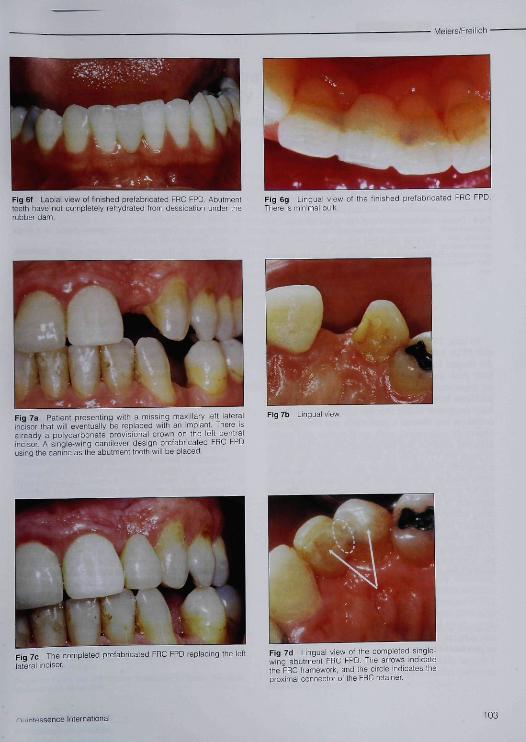
Fig 6f Labial view of linished prefabricated FRC FPD. Abutmentleeth have nol oonipietely rehydrated Ircm dessicaticn under therubber dam.
Fig 6g Linguai view ol the finished prefabricated FRC FPD.Theie is minimal bulk.
Fig 7a Patient presenting with a missing maxiiiary left lateralincisor that will eventually be replaced with an impiant. There isalready a polycarbonate piovisionai crown on the ieft centraiincisor. A single-wing cantilever design prefabricated FRC FPDusing the canine as the abutment tooth wiil be piaced
Fig 7b Lingual view
Fig 7c The completed prefabricated FRC FPD replacing the leftiaterai inciser.
Fig 16 Linguai view ot the oompleted singie-wing abutment FRC FPD. The arrows indicatethe FRC framework, and the oiicle indicates theproximal connector of the FRC retainer
/-I. lint essence Internationai 103

• Meiers/Freilich
ayer
Enamei Etched enamei/resin tags
Fig 8 Diagram illustrating the linguai FRC wing adaptation to tneabutment tootn. The following are snown: a thin iayer of iuting par-ticulate resin composite integrated with the adhesive into theetched enamei, the embedded FRC framework, and a thin iayer ofiow viscosity pafticuiate resin composite covering the exposedFRC framework The thickness of this complex is about 0.6 to 0,8mm
To date, 20 FRC/patiiculate resin composite chair-side FPDs have been placed, with one being irt placethe longest for over 42 months. These have involvedboth dual- and single-wing designs. There have heenno framework failures or debonding, and the onlyproblems have been minor repairs to the particulateresin composite veneer over the pontic. The presentedtechnique has allowed a predictable atid time-efficientchairside placetnent with predictable and easilyachieved esthetics and patient acceptance. The abilityto place the FPD with no tooth reduction also allowsa reversible procedure should other options (ie, singletooth implant) be considered in the future. The poten-tial for using a single abutment only with a cantileverapproach is an exciting option for tooth replacementusing adhesive dentistry and FRC technology. Clinicaltrials are being planned to evaluate the true potentialof this adhesive FPD to see if the recently developedpre-impregnated FRC technology can provide a sim-ple, noninvasive, durable, cost effective tooth replace-ment alternative.
ACKNOWLEDGMENTS
Ttie authors would like to acknowledge Dr Reza Ka^enii for ihe art-viiork of Figs la, Ib, and 14. and Jenenc/Pentron for supplying a par-tial grant for a lab technician.
REFERENCES
1, Antonson DE, Immediate temporary ...itlge using anextracted tooth. Dent Surv 1980;22:208-210,
2, Buonoeore MG, The Uses of Adhesives in Dentistry, Spring-field, [L: Charles C, Thomas, 1975:334,
3, Ibsen RL, Fixed prosthetics with a natural crown pontieusing adhesive composite. J South Calif Dent Assoc 1973;41:100-103,
4, Simonsen RJ. Ciinical Applications of the Acid Etch Tfechni-que, Chicago: Quintessence, 1978:71-80,
5, Ibsen RL, Neville K, Adhesive Restorative Dentistry, Phila-delphia: Saunders, 1974:139,
6, Davila JM, Gwinnett AV, Clinical and microscopic evalua-tion of a bridge using the acid-etch technique, ASDC J DentChild 1978;45:52-55,
7, Portnoy LL, Constructing a composite pontic in a singlevisit. Dent Surv 1973;49(8):20-24,
8, Simonsen RJ, The acid etch technique In fixed prostheses.An update (I), Quintessence Int 1980;11:33-40,
9, Stolpa JB, An adhesive technique for small anterior fixedpartial dentures. J Prosthet Dent 1975:34:513-516,
10, Simonsen R, Thompson V, Barrack G, Etched Cast Restora-tions: Clinical and Laboratory Techniques, Chicago: Quin-tessence, 1983.
11, Jensen ME, Meiers JC, Resin-bonded retainers. ClinicalDentistry, vo¡ 4, Philadelphia: Harper and Row, 1984:1-29,
12, Strassler HE, Gerhardt DE, Management of restorativeemergencies. Dent Clin North Am 1993;37:353-356,
13, Strassler HE, Planning with diagnostic casts for successwith direct composite bonding, f Esthet Dent 1995;7(1):32-40,
14, Littman H, Regan D, Rakow B, Provisional lemporizationwith acid-etcb technique. Clin Prev Dent 1980;2:14-16,
15, Sweeney EJ, Moore DL, Dooner JJ, Retentive strength ofacid etched fixed partial dentures: An in vitro comparisonof attachment techniques, J Am Dent Assoc 1980,100:198-205.
16, Goldberg AJ, Burstone CJ, The use of continuous fiher rein-forcement in dentistry. Dent Mater 1992:3:197-202,
17, Freilich MA, Karmaker AC, Burstone CJ, Goldberg AJ,Flexure strength and handling characteristics of fiber-rein-forced composites used in prosthodontics [abstract 1361],J Dent Res 1997;76:184,
18, Goldberg AJ, Preilich MA, Haser KA, Audi JH, Flexureproperties and fiber architecture of commercial fiber rein-forced composites [abstract 967|, J Dent Res 1998;77:226,
19, Meiers JC, Duncan JP, Freilich MA, Goldberg AJ, Pre-impregnated, fiher-reinforced prostheses. Part II, DirectApplications: Splints and fixed partial dentures. Quin-tessence Int 1998;29:761-768,
20, Freilich MA, Meiers JC, Duncan JP, Goldberg AJ, Fiber-Reinforced Composites in Clinical Dentistry, Chicago:Quintessence, 1999xbapter 4,
21, Freilich MA, Meiers JC, Duncan JP, Goldberg AJ, Fiber-Reinforced Composites in Clinical Dentstry. Chicago:Quintessence, 1999:chapter 2,
104 Volume 32, Number 2,


![[PPT]PREFABRICATED BUILDING - Wikispacescarlavl.wikispaces.com/file/view/PREFABRICATED+BUILDING.ppt · Web viewPREFABRICATED BUILDING Vargas, Valentina Vásquez, Carla CONTENT: Prefabricated](https://img.pdfslide.net/doc/110x75/5ada5d397f8b9a6d7e8ca107/pptprefabricated-building-buildingpptweb-viewprefabricated-building-vargas.jpg)