Embed Size (px)
Citation preview
5/13/2018 Challenge Cutter Titan 230 Operation Manual - slidepdf.com
http://slidepdf.com/reader/full/challenge-cutter-titan-230-operation-manual 1/40
I Serial Numbers 070001 & U
OPERATION·
MANUAL
TITAN230
PAPER CUTTING
MACHINE
Sold and Serviced by
F.230-0November 2007

5/13/2018 Challenge Cutter Titan 230 Operation Manual - slidepdf.com
http://slidepdf.com/reader/full/challenge-cutter-titan-230-operation-manual 2/40
* WARRANTY INFORMATION *
1.0 Introduction
1 .0 In troduction
THIS MANUAL is designed to help you get the most from your Challenge equipment. Keep this
manual in a safe, convenient place for quick reference by operators and service personnel.
'!D.\ijit.]~lsAFETY ALERT! This symbol means CAUTION: Personal safety
instructions! Pay special attention to the instructions in bold type. Personal injury may result if the
precautions are not read and followed.
READ THIS MANUAL BEFORE OPERATING! Follow precautions and instructions given and you
should have years of trouble-free operation. If after reading the manual questions still remain, contact
your Authorized Challenge Dealer.
Take a few minutes right nowto RECORD YOUR MACHINE SERIAL NUMBER in the space
provided on the front cover of this manual. Also be sure to fill out the warranty card accompanying
your machine and return it DIRECTLY TO CHALLENGE
If you bought a used machine, it is important to have the following information on record at Challenge.
Copy this page, fill in the information and send it care of The Challenge Service Department. 6125
Norton Center Drive. Norton Shores, MI 49417-1594.
CHALLENGE MODEL SERIAL NUMBER
ATTN COMPANY
ADDRESS
CITY STATE/PROVI NCE LZIP
PHONE DATE INSTALLED
DEALER NAME & CITY
It is very important that you read and understand the conditions outlined in the Warranty Information
Sheet attached to the outside of the shipping container of your machine.
The WafTanty Information Sheet must be filled out completely and returned to THE CHALLENGE
MACHINERY COMPANY in order for the warranty to be issued for this machine.
Chal lenge® is a registered trademark of The Chal lenge Machinery Company. 6125 Norton Center Drive. Norton Shores, MI
49441·6081Copydght© 2007 by The Challenge Machinery Company. All rights reserved. Printed in the U.S.A

5/13/2018 Challenge Cutter Titan 230 Operation Manual - slidepdf.com
http://slidepdf.com/reader/full/challenge-cutter-titan-230-operation-manual 3/40
2
1.0 Introd
TABLE OF CONTENTS
1.0 Introduction
2.0 Safety
2.1 Precautions2.2 Power Lockout Procedure
2.3 Warning Label Definitions
3.0 Packing List
4.0 Specifications
5.0 Installation & Setup
5.1 Inspecting Shipment.
5.2 Uncrating
5.3 Cleaning 1
5.4 Fitting Through Narrow Door 1
5.4.1 Removing the Side Tables 1
5.4.2 Removing the Table 1
5.4.3 Removing the Electric Eyes 1
5.4.4 Removing the Foot Treadle 1
5.4.5 Attaching the Table 1
5.4.6 Attaching the Electric Eyes 15.4.7 Attaching the Side Tables 1
5.5 Hydraulic System Check 1
5.6 False Clamp Plate (Optional) 1
5.7 Power Hook-Up 1
6.0 Operation 16.1 Power- Main Switch 1
6.2 Start Up 1
6.3 Making a Cut 1
6.4 Jogging Aid 1
6.5 Knife Change Alarm and Lubrication Alarm 1
6.6 Manual Clamping (Using the Foot Treadle) 1
6.7 Display Panel 2
6.8 Definition of Keys 2
6.8.1 Variable Speed Pinpoint Backgauge Control 2
6.8.2 IN/MM Key 2
6.8.3 Send Key 2
6.8.4 Push-Out Key/Hold-To-Run Backgauge Key 2
6.8.5 Clear Key 2
6.8.6 Enter Key 2
6.8.7 Priority Add (XIY) Key 26.8.8 Soft-Keys 2
6.8.9 Arrow Keys 2
6.8.10 Contrast Control... 2
6.9 Manual Backgauge ControL 2
6.9.1 Backgauge Glide ControL 2
6.9.2 Backlash Indicator 2
6.10 Send Mode 26.10.1 Entering Math 2
6.10.2 Entering Fractions 2
6.11 Maintena nce Mode 26.11.1 Knife Adjust. 2
6.11.2 Parameters 2
6.11.3 Diagnostic 2
6.11.4 Language 2
6.12 Job Mode 2
5/13/2018 Challenge Cutter Titan 230 Operation Manual - slidepdf.com
http://slidepdf.com/reader/full/challenge-cutter-titan-230-operation-manual 4/40
1.0 Introduction
6.12.1 Lock/Unlocking a Job 26
6.12.2 Copying a Job 26
6.12.3 Erasing a Job 26
6.12.4 Creating a New Job 26
6.12.5 Editing an Existing Job 27
6.12.6 Running a Programmed Job 28
6.12.7 Exiting a Job 286.13 An Example Job 28
6.14 Operating Tips 306.15 Note to Oealer 30
6.15.1 Entering the Dealer Name and Phone Number 30
7.0 Knife Installation/Changing 31
7.1 Knife Removal 31
7.2 Knife Installation 33
7.3 Knife Care Tips 34
7.3.1 Knife Blade Life 34
7.3.2 Cutting Stick 35
7.3.3 Bevel Angle 35
7.3.4 Helpful Suggestions 35
7.3.5 Knife Care 35
8.0 Titan 230 Floor Plan 37
9.0 Safety Systems Test 38
4

5/13/2018 Challenge Cutter Titan 230 Operation Manual - slidepdf.com
http://slidepdf.com/reader/full/challenge-cutter-titan-230-operation-manual 5/40
2.0
2.0 Safety
2.1 Precautions
• This machine is designed for one-person operation. Never operate the machine with more thanone person.
• Safe use of this machine is the responsibility of the operator. Use good judgment and common
sense when working with and around this machine.
• Read and understand all instructions thoroughly before using the machine. If questions remain,contact the dealer from which you purchased this machine. Failure to understand the operating
instructions may result in personal injury.
• Only trained and authorized people should operate this machine.
• DO NOT ALTER SAFETY GUARDS OR DEVICES. They are for your protection. Severe
personal injury may result.
• Disconnect power before cleaning or performing maintenance. See Section 2.2 Power Lockout
Procedure.
• Observe all caution labels on this machine.
• Be sure the cutter is properly grounded.• Be sure there is sufficient power to operate the cutter properly.
• Observe all caution plates mounted on this cutter.
• Keep foreign objects off table and away from cutter blade.
• BE EXTREMELY CAREFUL when handling and changing the cutter knife. Severe lacerations o
dismemberment could result from careless handling procedures.
• Keep the floor around the cutter free of trim, debris, oil and grease.
• When replacing hydraulic parts, loosen the connections slowly to release pressure. Never loose
connections with the machine running.
• If the cutter sounds or operates unusually, turn it off and consult the troubleshooting section of
this manual. If the problem cannot be corrected, have it checked by a qualified service person.
• CRUSH HAZARD, keep hand and fingers from under the clamp when clamping paper. UseJogging Aid to load paper, and use the backgauge to push paper out before unloading. DO NOT
REACH UNDER THE KNIFE AND CLAMP AREA!
2.2 Power Lockout Procedure
For maximum safety while making adjustments or repairs to your machine, be sure to disconnect
power to the machine. Disconnect the power plug from its socket
Figure 1 - Main Power Disconnect

5/13/2018 Challenge Cutter Titan 230 Operation Manual - slidepdf.com
http://slidepdf.com/reader/full/challenge-cutter-titan-230-operation-manual 6/40
2.0 Safety
HAZARDOUS AREA
2.3 W a rn in g L ab el D e fin itio n s
The following warning labels are found at various locations on your machine. Read and understand
the meaning of each symbol. If a label is lost from the machine, it should be replaced .
.
~"."~""""""""""""-----• I
· t> I
. I
: I
.01'
. . . _ . _ _ .. .
.
"I O W.
L _ _ _ _ _ _ _ _ _ _ _ _ _ _ _ _ _ _ _ _ _ _ _ ,_ , _ . _ . :
Disconnect power before cleaning, servicing, or making adjustments not requiringpower. Do not alter safety guards or devices; they are for your protection. Replace
all guards. Do not operate with any guards removed.
SHOCK HAZARD
Disconnect power before removing cover. Replace cover before operation.
SHOCK HAZARD
Disconnect power before removing cover. Replace cover before operation.
SINGLE OPERATOR
Do not operate with more than one person.
6

5/13/2018 Challenge Cutter Titan 230 Operation Manual - slidepdf.com
http://slidepdf.com/reader/full/challenge-cutter-titan-230-operation-manual 7/40
3,0 Pack
3.0 Packing List
Part No. Description Qty.
42007 Knife 2
42008 Cutting Stick (in addition to one installed in machine) 3
43108 Knife Lifter Assembly 1
F.230-0 Operator Manual 1
A-12608-2 Jogging Aid 1
20-2150-7 Tool Kit 1
5064 Cutting Stick Puller 1
W-130 3/16" Allen Wrench 1
W-137 5/32" Allen Wrench 1
W-164 5/16" Hex 'T' Wrench 1
W-170 9/16 x %" Wrench 1
SU-10-113 Grease Brush 1
Optional Items
Part No. Descri ption Qty,
41058 Waste Wagon
42007-1 High Speed Steel Knife
42008 Cutting Stick
42013 False Clamp Plate
5-7-M361 Backgauge Book Guides
50082 Magnetic Clamp Pads - Pkg of 2 - 3"x15" ea.
S-1991-4 Rykon 100 Hydraulic Oil - 5 gallon container
K-42050 Large Side Tables (18" x 20")

5/13/2018 Challenge Cutter Titan 230 Operation Manual - slidepdf.com
http://slidepdf.com/reader/full/challenge-cutter-titan-230-operation-manual 8/40
4.0 Specifications
4.0 Specifications
Description Inch Units Metric Units
Cutting Width 23" 58.4 emMinimum Cut* Y z " 13 mm
Clamp Opening 3 }4" 8.3 em
Table Space
Front: 24}4" 61.6 em
Back: 24" 61 em
Dimensions**
Table Height 36" 91.4 em
Overall Height 53" 135 em
Overall Length***'..-
66" 168 em
Overall Width 50" 127 emApprox. Net Weight 1,OOOlbs 454 kg
Approx. Shipping Weight 1,2501bs 567 kg
Electrical
208/230 Volts, 12 Amps, 1 Phase, 60 Hz, AC. Service size 15 AmpsRecommended Recepticle: 208-230 Volt, NEMA 6-15R, NEMA 6-20RUUcUL Listed
Sound Emission
A-weighted sound pressure level measured in an enclosed room at operator level
(6 feetl183 em):
Machine cutting a full lift of paper: 77 dB
*With false clamp plate attached, minimum cut is 1-7/8" (48 mm).**For complete floor plan layout, see page 37.
***With table, elec eyes, and foot treadle removed, can be fit through a 29" (74 cm) door opening.
Challenge reserves the right to make changes to any product or specification without notice and
without incurring responsibility to existing units.
8

5/13/2018 Challenge Cutter Titan 230 Operation Manual - slidepdf.com
http://slidepdf.com/reader/full/challenge-cutter-titan-230-operation-manual 9/40
5.0 Installation
5.0 Installation & Setup
5.1 Inspecting Shipment
This machine has been carefully packed to prevent damage during shipment. However, claims fordamage or loss are the responsibility of the recipient. Inspect all shipments as soon as they are
received. If there is any noticeable damage, note it on the freight bill. Visual and/or hidden damage
must be reported to the claims department of the carrier within 15 days. Contact your dealer if you
need any assistance. Check the contents of the box against the packing list on page 7. Make sure
there are no missing items.
5.2 Uncrating
The Titan 230 weighs approximately 1,000 Ibs (454 kg). DO NOT risk personal injury or damage by
attempting to move machinery with makeshift equipment or inadequate manpower. This machine isshipped on a wooden skid and enclosed in a protective, corrugated top. The skid is designed to allo
the machine to be rolled off without any special lifting equipment. The machine is held in place by
two, 2x4 braces lag bolted to the skid. All accessories are shipped inside of the machine.
Remove the carton by removing the nails or staples holding it to the skid and lift it straight up over th
cutter. If you don't have the ceiling clearance to do this, carefully slit the carton down the side and
then unwrap it from around the cutter.
Remove all lag screws from the skid. Remove the lower front cover of the Titan 230 and remove the
two lag screws in the base. Remove the accessories.
Using the rear bumper board, pry one side of the machine up, and slide out the top layer of the
support riser (Figure 2). Do the same on the other side.
Figure 2
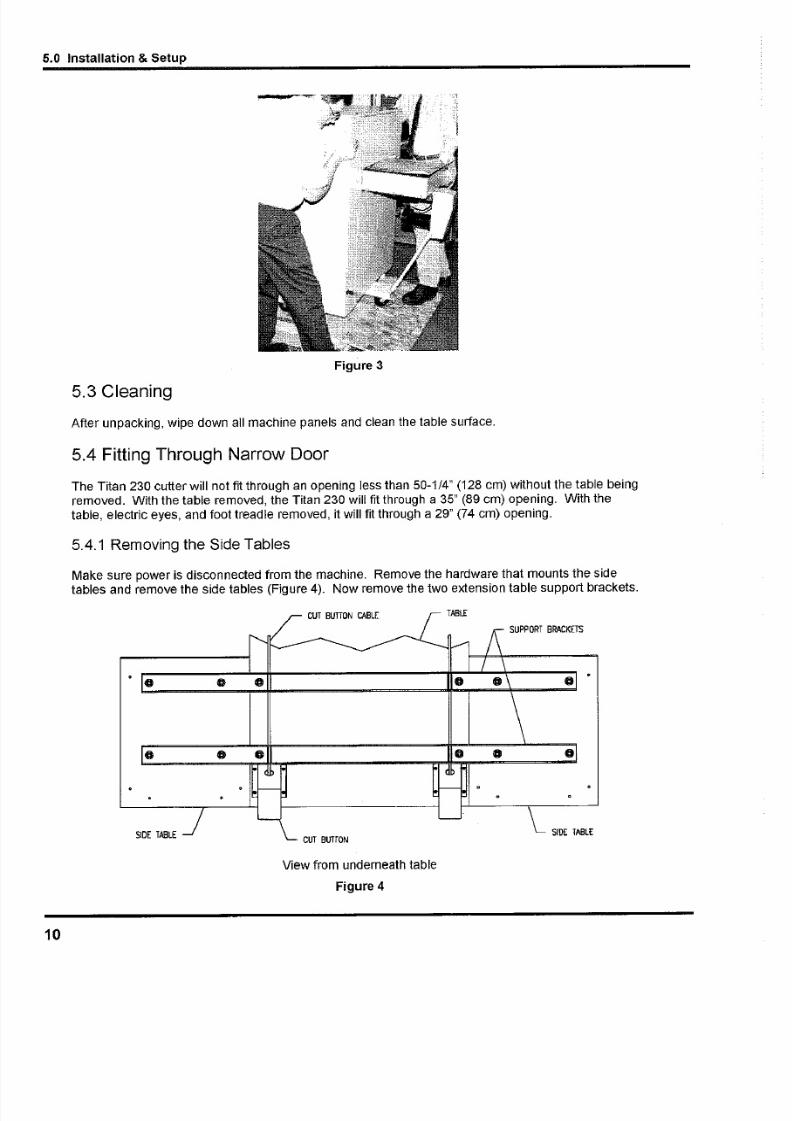
Use the flat board provided as a ramp and position as shown in (Figure 3 on page 10). Hold the ram
in place with the nails provided. Make sure the casters are not locked and very carefully roll the
machine down the ramp. The cutter may now be rolled into position.
5/13/2018 Challenge Cutter Titan 230 Operation Manual - slidepdf.com
http://slidepdf.com/reader/full/challenge-cutter-titan-230-operation-manual 10/40
5.0 Installation & Setup
Figure 3
5.3 Cleaning
After unpacking, wipe down all machine panels and clean the table surface.
5.4 Fitting Through Narrow Door
The Titan 230 cutter will not fi t through an opening less than 50-1/4" (128 cm) without the table being
removed. With the table removed, the Titan 230 will fi t through a 35" (89 cm) opening. With the
table, electric eyes, and foot treadle removed, it will f it through a 29" (74 cm) opening.
5.4.1 Removing the Side Tables
Make sure power is disconnected from the machine. Remove the hardware that mounts the sidetables and remove the side tables (Figure 4). Now remove the two extension table support brackets.
o
C U T B U T T O N C A B L E
S U PP O RT B R AC K ET S
S I D E T A B L EC U T B U T TO N
S I D E T A B L E
View from underneath table
Figure 4
10
5/13/2018 Challenge Cutter Titan 230 Operation Manual - slidepdf.com
http://slidepdf.com/reader/full/challenge-cutter-titan-230-operation-manual 11/40
5.0 Installation
5.4.2 Removing the Table
1. Make sure the knife and clamp are in the "up" position. If they are not, read the PowerHookup section (page 16) to connect power to the machine. Turn on the power using the re
and yellow main power switch and press the CLEAR button. This will preset the backgauge
and send the knife and clamp up.
2. Turn off the machine and unplug the power cord.
3. Make sure the side tables and side table mounting brackets have been removed (seeprevious section).
4. Remove the cut buttons from the bottom of the table.
5. Remove all rear covers that are on the rear of the table. Remove the backgauge motor
cover, the rear table support leg, the lower back panel, and the lower front cover of the
machine.
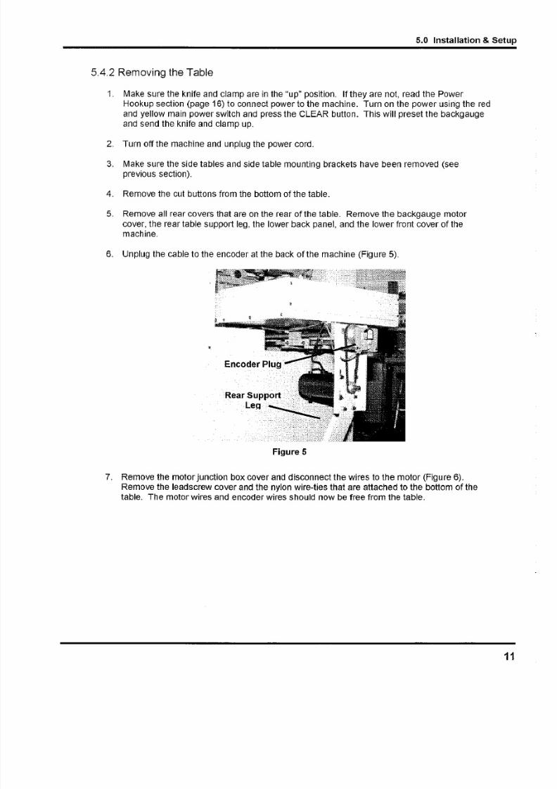
6. Unplug the cable to the encoder at the back of the machine (Figure 5).
Figure 5
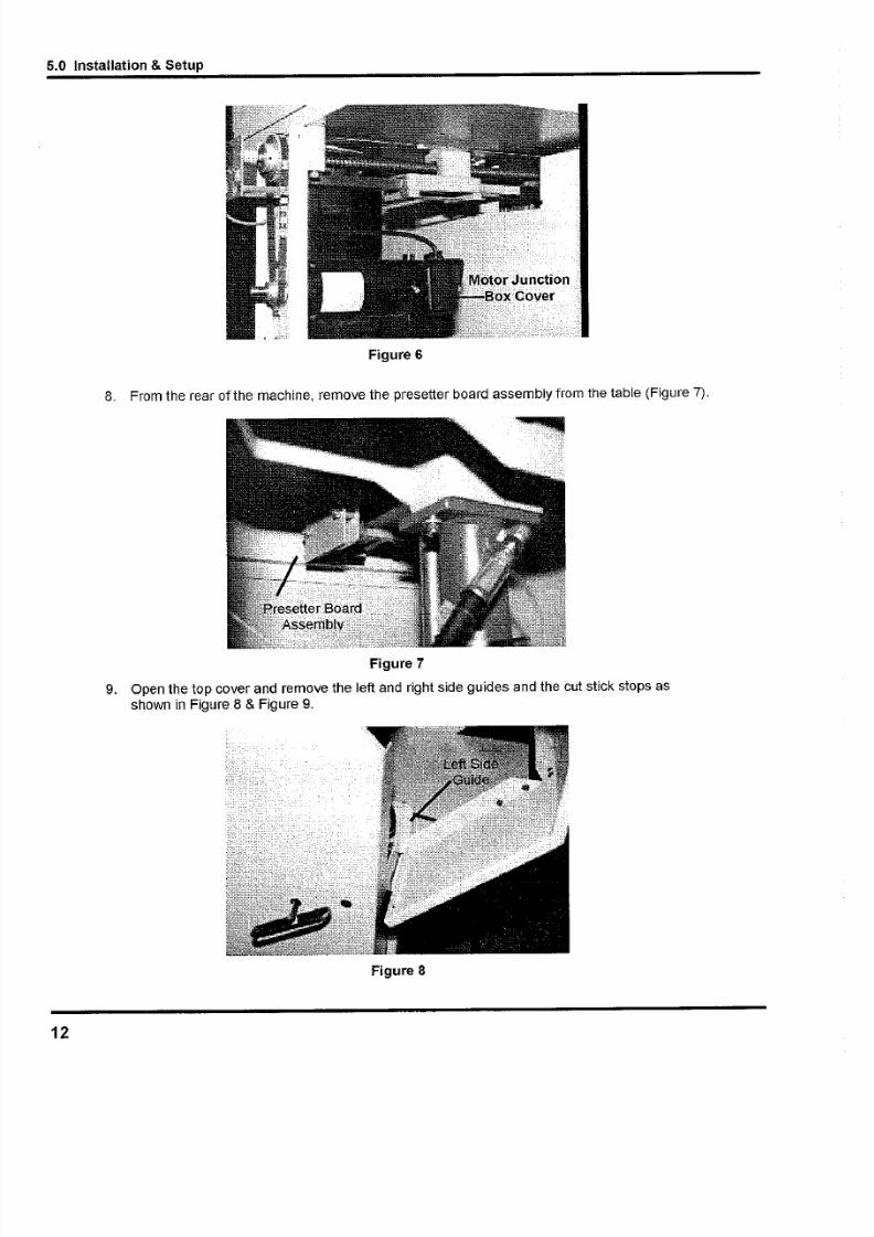
7. Remove the motor junction box cover and disconnect the wires to the motor (Figure 6).
Remove the leads crew cover and the nylon wire-ties that are attached to the bottom of the
table. The motor wires and encoder wires should now be free from the table.
5/13/2018 Challenge Cutter Titan 230 Operation Manual - slidepdf.com
http://slidepdf.com/reader/full/challenge-cutter-titan-230-operation-manual 12/40
5.0 Installation & Setup
Figure 6
8. From the rear of the machine, remove the presetter board assembly from the table (Figure 7).
Figure 7
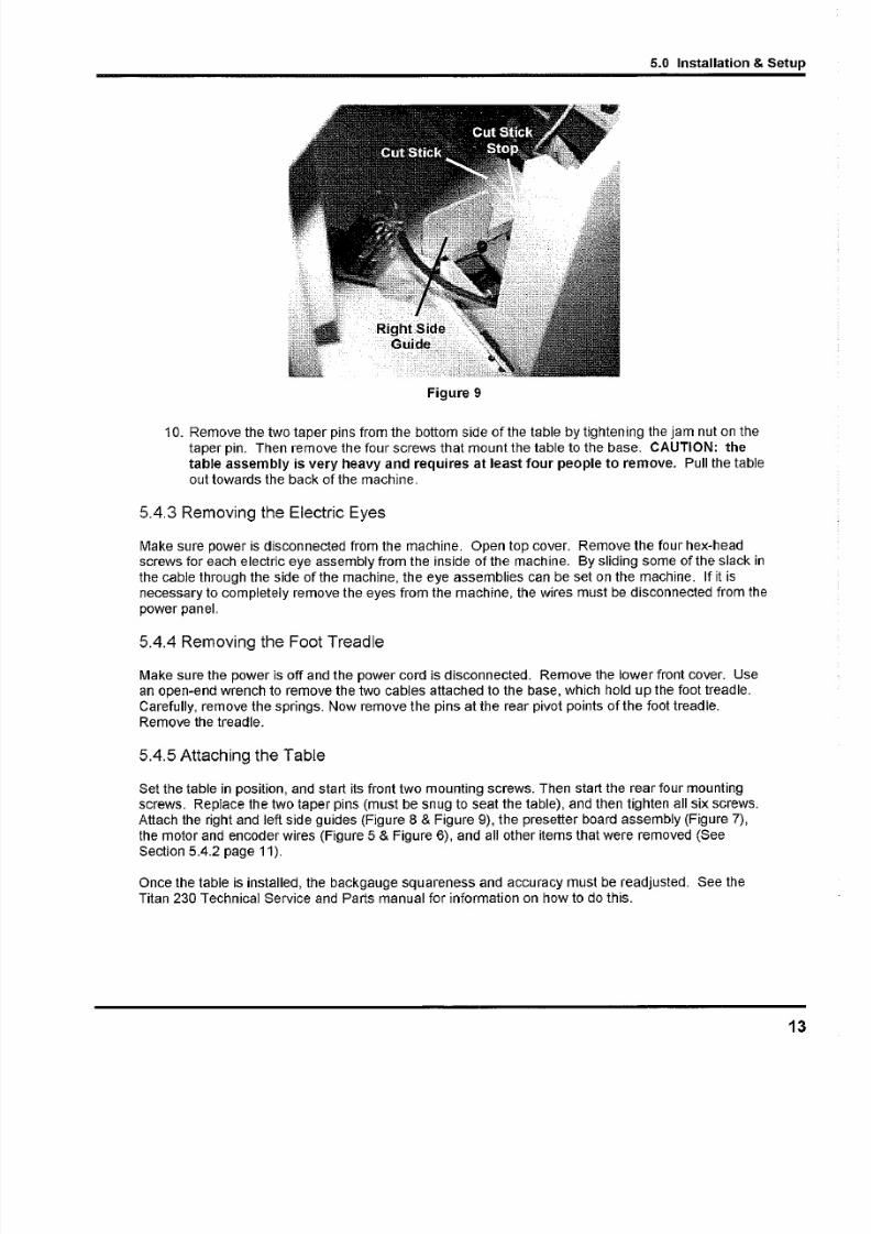
9. Open the top cover and remove the left and right side guides and the cut stick stops asshown in Figure 8 & Figure 9.
Figure 8
12
5/13/2018 Challenge Cutter Titan 230 Operation Manual - slidepdf.com
http://slidepdf.com/reader/full/challenge-cutter-titan-230-operation-manual 13/40
5.0 Installation
Figure 9
10. Remove the two taper pins from the bottom side of the table by tightening the jam nut on the
taper pin. Then remove the four screws that mount the table to the base. CAUTION: the
table assembly is very heavy and requires at least four people to remove. Pull the tabl
out towards the back of the machine.
5.4.3 Removing the Electric Eyes
Make sure power is disconnected from the machine. Open top cover. Remove the four hex-headscrews for each electric eye assembly from the inside of the machine. By sliding some of the slack
the cable through the side of the machine, the eye assemblies can be set on the machine. If it is
necessary to completely remove the eyes from the machine, the wires must be disconnected from th
power panel.
5.4.4 Removing the Foot Treadle
Make sure the power is off and the power cord is disconnected. Remove the lower front cover. Use
an open-end wrench to remove the two cables attached to the base, which hold up the foot treadle.
Carefully, remove the springs. Now remove the pins at the rear pivot paints of the foot treadle.
Remove the treadle.
5.4.5 Attaching the Table
Set the table in position, and start its front two mounting screws. Then start the rear four mounting
screws. Replace the two taper pins (must be snug to seat the table), and then tighten all six screws.
Attach the right and left side guides (Figure 8 & Figure 9), the presetter board assembly (Figure 7),
the motor and encoder wires (Figure 5 & Figure 6), and all other items that were removed (See
Section 5.4.2 page 11).
Once the table is installed, the backgauge squareness and accuracy must be readjusted. See the
Titan 230 Technical Service and Parts manual for information on how to do this.

5/13/2018 Challenge Cutter Titan 230 Operation Manual - slidepdf.com
http://slidepdf.com/reader/full/challenge-cutter-titan-230-operation-manual 14/40
5.0 Installation & Setup
5.4.6 Attaching the Electric Eyes
Make sure power is disconnected from the machine. If necessary, connect the wires to the powerpanel. Attach electric eye assemblies with provided hardware, making sure that the bottom of the
electric eye housings are parallel to the table. Once power is hooked up, the electric eyes should be
checked for alignment. See the Titan 23D Technical Service and Parts manual for information on how
to do this.
5.4.7 Attaching the Side Tables
Using (4) 3/8-16 cap screws and washers, attach the table supports to the under side of the maintable (Figure 1D), making sure to route each cut button cable through the slots in the brackets. Lay
the side tables on top of the support brackets and insert the mounting hardware. Slide the table
extension tight to the table and tighten the hardware.
C U T B U T T O N C A B L E
S U P PO R T B R A CK ET S
o
C U T B U T TO NS ID E T A BL EID E T AB LE
View from underneath table
Figure 10
5.5 Hydraulic System Check
The cutting/clamping mechanism of the Titan 23D is powered by a hydraulic system consisting of an
electric motor coupled directly to a hydraulic pump.
The hydraulic reservoir holds 4 quarts (1 gallon) of hydraulic fluid. It is filled with Rykon 100 hydraulic
fluid at the factory but should be checked before operation. Remove the lower rear panel cover andunscrew the cap on top of the tank (Figure 11 on page 15). Fluid level should be at 1/8" from the endof the dip stick (check with dip stick cap screwed in). Add fluid if necessary but avoid overfilling as
this could cause leakage when hot. Replace the rear panel when finished. For more information
about checking and changing the hydraulic fluid, including a cross-reference chart of approved fluids,
see the Titan230 Technical Service and Parts manual.
The hydraulic fluid should be checked weekly and changed AT LEAST ONCE-A-YEAR or after every
1,ODDhours of operation.
14
5/13/2018 Challenge Cutter Titan 230 Operation Manual - slidepdf.com
http://slidepdf.com/reader/full/challenge-cutter-titan-230-operation-manual 15/40
5.0 Installation
Figure 11
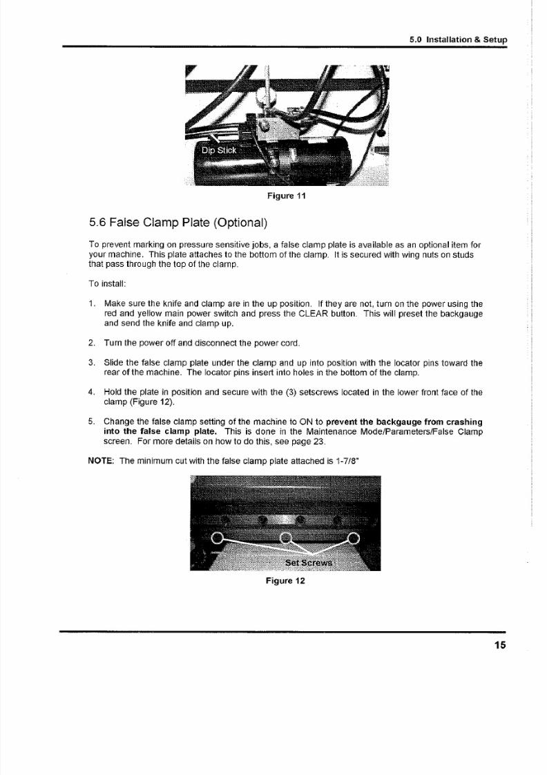
5.6 False Clamp Plate (Optional)
To prevent marking on pressure sensitive jobs, a false clamp plate is available as an optional item fo
your machine. This plate attaches to the bottom of the clamp. It is secured with wing nuts on studs
that pass through the top of the clamp.
To install:
1. Make sure the knife and clamp are in the up position. If they are not, turn on the power using th
red and yellow main power switch and press the CLEAR button. This will preset the backgaug
and send the knife and clamp up.
2. Turn the power off and disconnect the power cord.
3. Slide the false clamp plate under the clamp and up into position with the locator pins toward threar of the machine. The locator pins insert into holes in the bottom of the clamp.
4. Hold the plate in position and secure with the (3) setscrews located in the lower front face of thclamp (Figure 12).
5. Change the false clamp setting of the machine to ON to prevent the backgauge from crashin
into the false clamp plate. This is done in the Maintenance Mode/Parameters/False Clam
screen. For more details on how to do this, see page 23.
NOTE: The minimum cut with the false clamp plate attached is 1-7/8"
Figure 12
5/13/2018 Challenge Cutter Titan 230 Operation Manual - slidepdf.com
http://slidepdf.com/reader/full/challenge-cutter-titan-230-operation-manual 16/40
5.0 Installation & Setup
5.7 P o we r H o ok -U p
ACAUTIONSHOCK HAZARD! NEVER CUT THE GROUND PLUG from a three-prong
plug to fit a two-prong socket. Possible shock could cause personal injury or death. Hire a qualified
electrician to provide a power source that meets electrical requirements and all local electrical codes.
It is the customer's responsibility to provide a properly grounded receptacle that meets the power
requirements specified on the nameplate of this machine, as well as all local electrical codes. Have a
qualif ied electrician install one if your location is not so equipped.
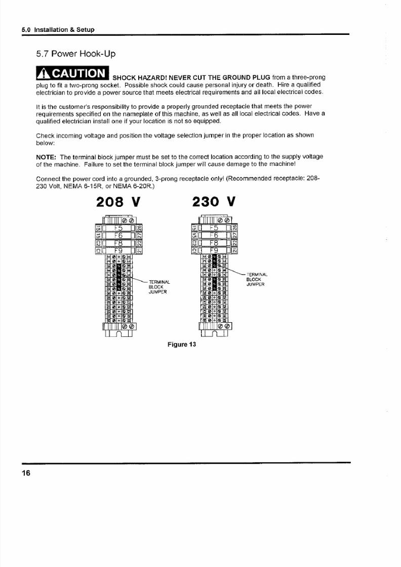
Check incoming voltage and position the voltage selection jumper in the proper location as shownbelow:
NOTE: The terminal block jumper must be set to the correct location according to the supply voltage
of the machine. Failure to set the terminal block jumper will cause damage to the machine!
Connect the power cord into a grounded, 3-prong receptacle only! (Recommended receptacle: 208-
230 Volt, NEMA 6-1SR, or NEMA 6-20R.)
208 V 230 V
I ~ I 1 1 1 1 I @ @0; F5 f <DN0;0 F6 D~o F8 NN N~ F9 N
"0 O(§)
00 o®;0 (§)
"'0 I$)
"0 1'$
0 I$)
" ' ' ' ' I$)
1::0 I$)
11:0 01$)
a" , O(§)
~ '" 01$)-
+ ' " 01$)+ ' " 01$).
:'" 01$)
0C § l
I ~ I @@L.L___J
1__lj
TERMINAL
BLOCK
JUMPER
J I I I I I I e et n l L i F5 l <DNt n lO F6 D~8]U F8 J NN~ J O F9 O N
0 ®
0 ®-0 r&
00® r - - - -0 o®
flJ ®
flJ ®
" ' 1 i ! I ®00®"0a ® ~
~0 o ® ~
00 ® ~
1:0 o® •
00 ®;
0" ®.
m I . @@L__fLJJ
TERMINAL
BLOCK
JUMPER
Figure 13
16

5/13/2018 Challenge Cutter Titan 230 Operation Manual - slidepdf.com
http://slidepdf.com/reader/full/challenge-cutter-titan-230-operation-manual 17/40
6.0 Op
6.0 Operation
ACAUTION IMPORTANT: DO NOT ATTEMPT TO OPERATE THE CUTTER UNTIL
YOU HAVE THOROUGHLY READ AND UNDERSTAND ALL OF THE FOLLOWING
INSTRUCTIONS. CALL YOUR AUTHORIZED CHALLENGE DEALER IF YOU STILL HAVE ANY
QUESTIONS.
6.1 Power - Main Switch
Power is brought to the machine when the main power switch is turned to the "ON" position (Figure
14). The display and line lights are turned on at this time. The hydraulic motor will not be activated
until a cut cycle is initiated, and it will shut off after the completion of the cut cycle.
ON ON
Figure 14 -Power On-Off Switches
The display and line lights will shut off after 5 minutes without any activity. This shut-off time can be
changed in the Parameters screen of the Maintenance Mode (section 6.11.2 on page 23). To restor
power to the display and line lights, press any button on the keyboard.
6.2 Start Up
Once power has been turned on, the Titan 230 will show the following display:
55.000 in
Backgauge must move to be preset.
Please clear the table.
Warning! Clamp and Knife may move.
Revision 1.0
Press clear to start
A) MaintB) Job
When the CLEAR key is pressed the clamp and knife will move up if they are not already in the up
position. Then the backgauge will move to coordinate the true position into the computer. When
5/13/2018 Challenge Cutter Titan 230 Operation Manual - slidepdf.com
http://slidepdf.com/reader/full/challenge-cutter-titan-230-operation-manual 18/40
6.0 Operation
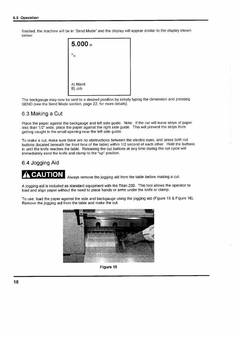
finished, the machine will be in "Send Mode" and the display will appear similar to the display shownbelow:
5.000 in
>
A) MaintB) Job
The backgauge may now be sent to a desired position by simply typing the dimension and pressingSEND (see the Send Mode section, page 22, for more details).
6.3 Making a CutPlace the paper against the backgauge and left side guide. Note: Ifthe cut will leave strips of paperless than 1/2" wide, place the paper against the right side guide. This will prevent the strips from
getting caught in the small opening near the left side guide.
To make a cut, make sure there are no obstructions between the electric eyes, and press both cut
buttons (located beneath the front face of the table) within 1/2 second of each other. Hold the buttons
in until the knife reaches the table. Releasing the cut buttons at any time during the cut cycle will
immediately send the knife and clamp to the "up" position.
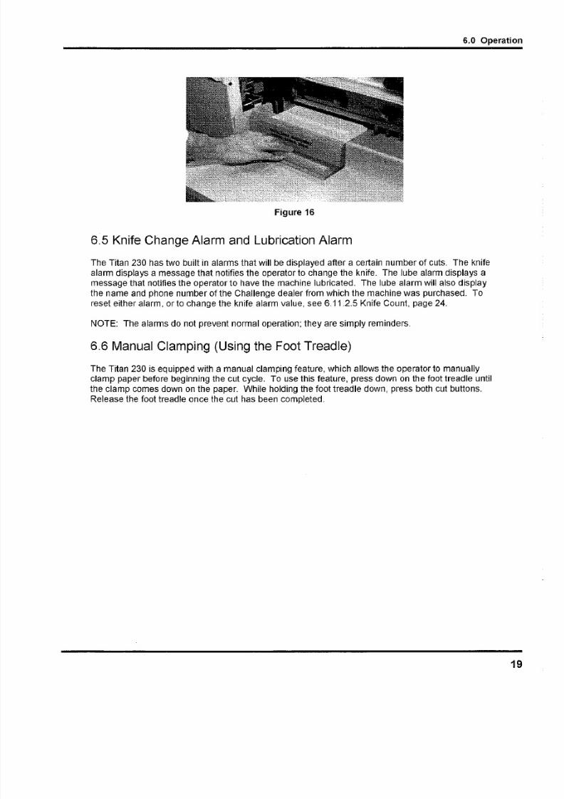
6.4 Jogging Aid
ACAUTION Always remove the jogging aid from the table before making a cut.
A jogging aid is included as standard equipment with the Titan 230. This tool allows the operator to
load and align paper without the need to place hands or arms under the knife or clamp.
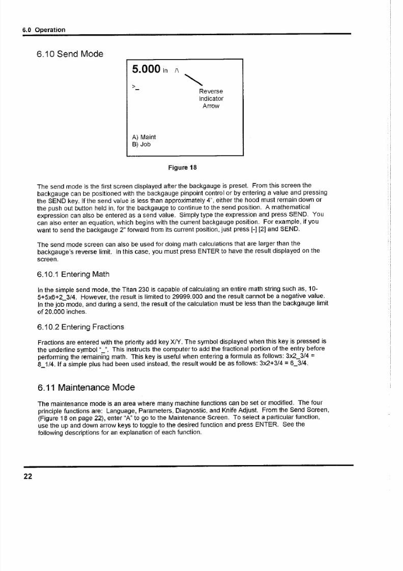
To use, load the paper againstthe side and backgauge using the jogging aid (Figure 15 & Figure 16).
Remove the jogging aid from the table and make the cut.
Figure 15
18
5/13/2018 Challenge Cutter Titan 230 Operation Manual - slidepdf.com
http://slidepdf.com/reader/full/challenge-cutter-titan-230-operation-manual 19/40
6.0 Op
Figure 16
6.5 Knife Change Alarm and Lubrication Alarm
The Titan 230 has two built in alarms that will be displayed after a certain number of cuts. The knife
alarm displays a message that notifies the operator to change the knife. The lube alarm displays amessage that notifies the operator to have the machine lubricated. The lube alarm will also display
the name and phone number of the Challenge dealer from which the machine was purchased. To
reset either alarm, or to change the knife alarm value, see 6.11.2.5 Knife Count, page 24.
NOTE: The alarms do not prevent normal operation; they are simply reminders.
6.6 Manual Clamping (Using the Foot Treadle)
The Titan 230 is equipped with a manual clamping feature, which allows the operator to manuallyclamp paper before beginning the cut cycle. To use this feature, press down on the foot treadle unti
the clamp comes down on the paper. While holding the foot treadle down, press both cut buttons.
Release the foot treadle once the cut has been completed.

5/13/2018 Challenge Cutter Titan 230 Operation Manual - slidepdf.com
http://slidepdf.com/reader/full/challenge-cutter-titan-230-operation-manual 20/40
6.0 Operation
6.7 Display Panel
Displa SEND y IN MM Key
Variable SpeedPinpoint Backgauge
Control
Soft
Keys
rrow Keys
CLEAR Key
Figure 17
6.8 Definition of Keys
6.8.1 Variable Speed Pinpoint 8ackgauge Control
The backgauge control is used to manually position the backgauge. The speed of the backgauge will
depend upon where the actuator is pressed. Press farther from center for a faster speed. Presstoward the operator for forward direction and away from the operator for reverse direction.
6.8.2 IN/MM Key
This key toggles the display to show the position and programmed send values in inches (e.g. 5.250),
inch fractions to the nearest 1/64" (e.g. 5_1 / ; Y , or millimeters (e.g. 133.3).
6.8.3 Send Key
The SEND key is used to send the backgauge to any valid position. If an attempt is made to send the
backgauge to an illegal position, an error message will be displayed at the bottom of the screen
stating "Number outside limit". In the Job mode, the SEND key will also advance the backgauge to
the next sequential cut position before performing the cut.
6.8.4 Push-Out Key/Hold-To-Run 8ackgauge Key
This key has 2 functions. It is used to move the backgauge forward 5 inches (or to the most forward
position) and then return it to its previous position. This allows paper to be removed from the cutter
without putting hands under the knife and clamp. It also allows backgauge to move forward under
program control if the electric eyes are blocked for dimensions less than 3.5 inches (8.9 ern).
20

5/13/2018 Challenge Cutter Titan 230 Operation Manual - slidepdf.com
http://slidepdf.com/reader/full/challenge-cutter-titan-230-operation-manual 21/40
6.0 O
Never place hands in the clamp and knife area. Use the push-out key othe backgauge glide control to move the paper to an area where it can be reached.
ACAUTION
6.8.5 Clear Key
The CLEAR key is used to clear error messages and the current entry line.
6.8.6 Enter Key
The ENTER key selects items in the maintenance mode and processes data that has been enteredthe other modes.
6.8.7 Priority Add (XJY ) Key
The priority add key is used for entering fractions when they are combined with whole numbers. The
symbol displayed when this key is pressed is the underline symbol "_". An example of a number
entered using the priority add key is 1_1/2 (see 6.10.2 Entering Fractions, page 22).
6.8.8 Soft-Keys
The soft-keys are labeled as A, S, C, and D. The definition for these keys change depending on the
operating mode. The function of the key can be found on the bottom of the display screen.
6.8.9 Arrow Keys
The four arrow keys can be used in almost all screens. The arrow keys are primarily used for movinthe cursor around on the screen, orto toggle between highlighted selections. In some screens, the
left arrow key acts as a backspace key.
6.8.10 Contrast Control
The contrast of the display can be adjusted by using the contrast control knob, which is locateddirectly behind the display panel, sticking out of the display panel cover.
6.9 Manual Backgauge Control
6.9.1 Backgauge Glide Control
The backgauge can be moved manually by use of the backgauge glide control. Press towards the
operator for forward travel and away from the operator for reverse travel. The further away from
center that the actuator is pushed, the faster the backgauge will travel.
6.9.2 Backlash Indicator
To insure accurate cuts, the backgauge must be brought to the cut position from the rear of the tabl
In the display, to the right of the backgauge position, there is a small arrow to indicate reverse trav
(Figure 18). This arrow should be off when making a cut. Moving back past your cut position, theforward to it, compensates for any play in the backgauge nut and leadscrew.
5/13/2018 Challenge Cutter Titan 230 Operation Manual - slidepdf.com
http://slidepdf.com/reader/full/challenge-cutter-titan-230-operation-manual 22/40
Reverse
IndicatorArrow
6.0 Operation
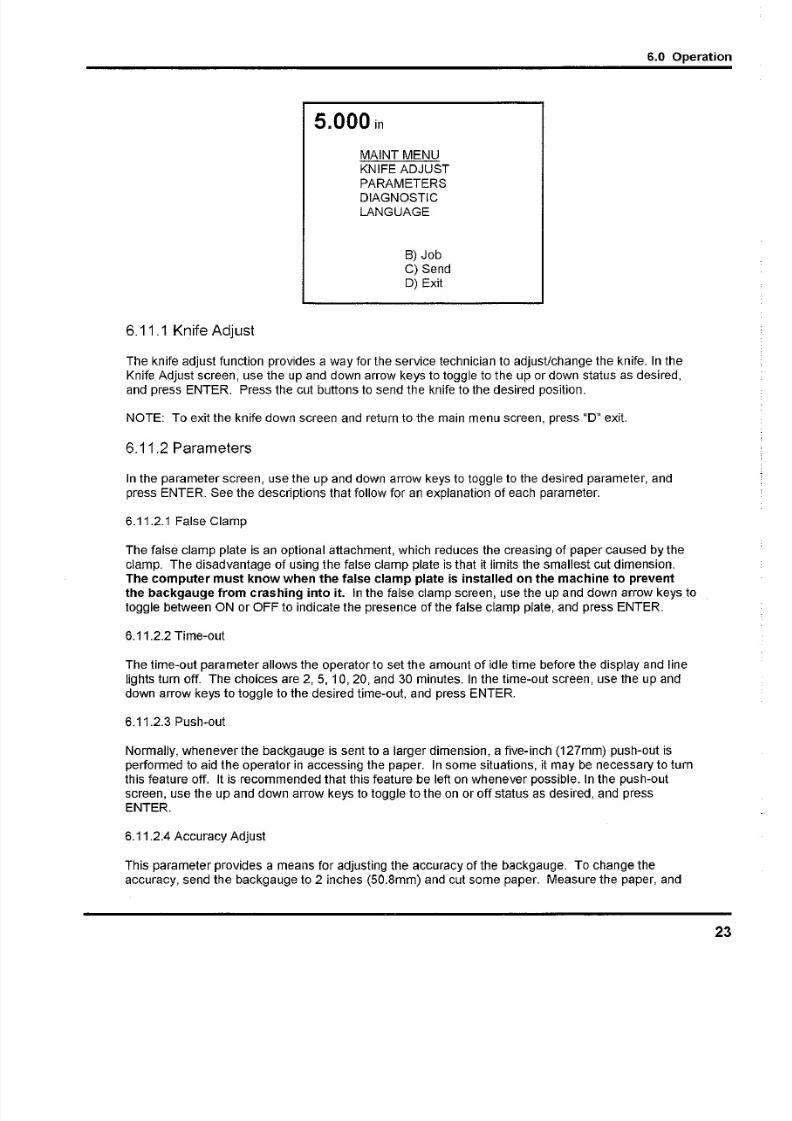
6.10 Send Mode
5.000 in /\
>
A) Maint8) Job
Figure 18
The send mode is the first screen displayed after the backgauge is preset. From this screen the
backgauge can be positioned with the backgauge pinpoint control or by entering a value and pressingthe SEND key. If the send value is less than approximately 4", either the hood must remain down Of
the push out button held in, for the backgauge to continue to the send position. A mathematical
expression can also be entered as a send value. Simply type the expression and press SEND. You
can also enter an equation, which begins with the current backgauge position. For example, if you
want to send the backgauge 2" forward from its current position, just press [-1[21and SEND.
The send mode screen can also be used for doing math calculations that are larger than the
backgauge's reverse limit. In this case, you must press ENTER to have the result displayed on the
screen.
6.10.1 Entering Math
In the simple send mode, the Titan 230 is capable of calculating an entire math string such as, 10-
5+5x6+2_3/4. However, the result is limited to 29999.000 and the result cannot be a negative value.
In the job mode, and during a send, the result of the calculation must be less than the backgauge limitof 20.000 inches.
6.10.2 Entering Fractions
Fractions are entered with the priority add key XfY. The symbol displayed when this key is pressed is
the underline symbol "_". This instructs the computer to add the fractional portion of the entry before
performing the remaining math. This key is useful when entering a formula as follows: 3x2_3/4 =8_1/4. If a simple plus had been used instead, the result would be as follows: 3x2+3/4 = 6_3/4.
6.11 Maintenance Mode
The maintenance mode is an area where many machine functions can be set or modified. The four
principle functions are: Language, Parameters, Diagnostic, and Knife Adjust. From the Send Screen,(Figure 18 on page 22), enter "A" to go to the Maintenance Screen. To select a particular function,
use the up and down arrow keys to toggle to the desired function and press ENTER. See the
following descriptions for an explanation of each function.
22
5/13/2018 Challenge Cutter Titan 230 Operation Manual - slidepdf.com
http://slidepdf.com/reader/full/challenge-cutter-titan-230-operation-manual 23/40
6.0 Op
8) Job
C) SendD) Exit
5.000 in
MAINT MENU
KNIFE ADJUST
PARAMETERS
DIAGNOSTIC
LANGUAGE
6.11.1 Knife Adjust
The knife adjust function provides a way for the service technician to adjust/change the knife. In the
Knife Adjust screen, use the up and down arrow keys to toggle to the up or down status as desired,
and press ENTER. Press the cut buttons to send the knife to the desired position.
NOTE: To exit the knife down screen and return to the main menu screen, press "0" exit.
6.11.2 Parameters
In the parameter screen, use the up and down arrow keys to toggle to the desired parameter, and
press ENTER. See the descriptions that follow for an explanation of each parameter.
6.11.2.1 False Clamp
The false clamp plate is an optional attachment, which reduces the creasing of paper caused by the
clamp. The disadvantage of using the false clamp plate is that it limits the smallest cut dimension.
The computer must know when the false clamp plate is installed on the machine to preventthe backgauge from crashing into it. In the false clamp screen, use the up and down arrow keys
toggle between ON or OFF to indicate the presence of the false clamp plate, and press ENTER.
6.11.2.2 Time-out
The time-out parameter allows the operator to set the amount of idle time before the display and line
lights turn off. The choices are 2, 5, 10,20, and 30 minutes. In the time-out screen, use the up and
down arrow keys to toggle to the desired time-out, and press ENTER.
6.11.2.3 Push-out
Normally, whenever the backgauge is sent to a larger dimension, a five-inch (127mm) push-out is
performed to aid the operator in accessing the paper. In some situations, it may be necessary to turnthis feature off. It is recommended that this feature be left on whenever possible. In the push-out
screen, use the up and down arrow keys to toggle to the on or off status as desired, and press
ENTER.
6.11.2.4 Accuracy Adjust
This parameter provides a means for adjusting the accuracy of the backgauge. To change the
accuracy, send the backgauge to 2 inches (50.8mm) and cut some paper. Measure the paper, and

5/13/2018 Challenge Cutter Titan 230 Operation Manual - slidepdf.com
http://slidepdf.com/reader/full/challenge-cutter-titan-230-operation-manual 24/40
6.0 Operation
type in what you actually measure. The computer will calculate the amount of error and will
compensate.
6.11.2.5 Knife Count
The knife count parameter allows the operator to reset the knife alarm and the lube alarm. The knife
alarm displays a message that notifies the operator to change the knife. The lube alarm displays amessage that notifies the operator to have the machine lubricated. The lube alarm will also display
the name and phone number of the Challenge dealer from which the machine was purchased.
NOTE: The alarms do not prevent normal operation they are simply reminders.
There are three functions within the knife count parameter: Clear Count, Knife Alarm, and Clear
Lube. Select the desired function and press ENTER. See the following descriptions for an
explanation of each function.
Select Clear count to reset the knife counter when a knife change has been performed.
Select Knife Alarm to enter or change the knife stroke alarm value. When this value is reached, the
display will alert you to cha nge the knife and reset the knife counter. Knife alarm values for the Titan
230 are factory set at 2,500 cuts. However, you may want to change this value based on your
specific machine applications. See 7.3 Knife Care Tips, page 34 for help in choosing a knife alarmvalue for your machine.
Select Clear lube to reset the lube alarm after performing the lubrication requirements as shown in
the Titan 230 Technical Service and Parts manual. Note: The number of cuts needed to set off the
alarm is programmed at the factory and cannot be changed.
6.11.2.6 Machine count
The number displayed is the total number of cuts made by the machine.
6.11.3 Diagnostic
The diagnostic area can be very helpful in locating a problem in the event of a machine malfunction.Use the up and down arrow keys to toggle to the desired selection, and press ENTER. See the
following descriptions for an explanation of each.
A) Maint
8) Job
C) Send
D) Exit
5.000 in
DIAGNOSTIC
Error Code
Sensor Data
Clear Memory
Electric Clamp
Clamp Adjust
24

5/13/2018 Challenge Cutter Titan 230 Operation Manual - slidepdf.com
http://slidepdf.com/reader/full/challenge-cutter-titan-230-operation-manual 25/40
6.0 Op
6.11.3.1 Error Code
The Error Code function simply recalls the last five error messages that were displayed. This can be
very useful in cases when the malfunction cannot be reproduced in the presence of the service
technician.
6.11.3.2 Sensor Data
The Sensor Data function provides a list of computer inputs and outputs (proximity switches, etc.)
along with their status (0 for open, 1 for closed). This function allows a service technician to check
the status of a switch without removing any covers. Cuts and backgauge movements are allowed in
this screen so that the technician may observe the status of the inputs and outputs during machine
operation.
6.11.3.3 Clear Memory
The Clear Memory function resets the memory to a known state. All cut positions will be erased
during this operation.
6.11.3.4 Electric Clamp
This function turns the optional electric clamp pressure control on or off.
6.11.3.5 Clamp Adjust
This function allows for the adjustment of the electric clamp function.
6.11.4 Language
In the language screen, use the up and down arrow keys to toggle to the desired language, and pres
ENTER. All messages will be displayed in the selected language.
6.12 Job ModeThe Titan 230 can be programmed for up to 99 different jobs or channels. A job is used for making
sequence of cuts using the send (or cut) values of the job as the backgauge positions for each cut.
Each job can hold up to 99 send values. If 2 channels are linked, up to 198 send values can be
accessed from one job. When the job mode is entered, all previously programmed jobs will be
displayed along with their name and lock status. Locked jobs will be indicated by an asterisk "*". A
plus "+" sign at the bottom of the screen indicates there are more jobs programmed than what are
displayed. An example of a job mode screen display is shown below.
>
1> JOB 1
2>TESTJOB
5>6> BOBS JOB *
7> 8.5 X 11 *
9>
10>+
A) Lock C) Erase
B) Copy D) Exit
5/13/2018 Challenge Cutter Titan 230 Operation Manual - slidepdf.com
http://slidepdf.com/reader/full/challenge-cutter-titan-230-operation-manual 26/40
6.0 Operation
6.12.1 Lock/Unlocking a Job
In the Job Mode screen, the soft-key "A" will display "Lock" or "Unlock" depending on the currentstatus of the job. If a job is locked, an asterisk "*"will be displayed to the right of the job name. To
change the lock status of a job, simply move the cursor to the desired job using the up and down
arrow keys, and press the soft-key "A" (Lock/Unlock).
6.12.2 Copying a Job
First, select a job to copy by moving the cursor up or down to the desired job number and press the
soft-key "B" (Copy). "Select Copy to #" will be displayed at the bottom of the screen. Enter a job
number for the new job or move the cursor to an existing job and press ENTER. If the new job is
locked, the copy will not be allowed. NOTE: if the new job is not locked, but contains data, the old
data WILL BE LOST.
6.12.3 Erasing a Job
Select a job to erase by moving the cursor to the desired job. Press the soft-key "C" (Erase). "Clearchannel #" will be displayed, followed by YES or NO. Use the up and down arrow keys to toggle to
YES or NO. YES will erase the job, NO will leave the job unchanged. NOTE: locked jobs can beerased!
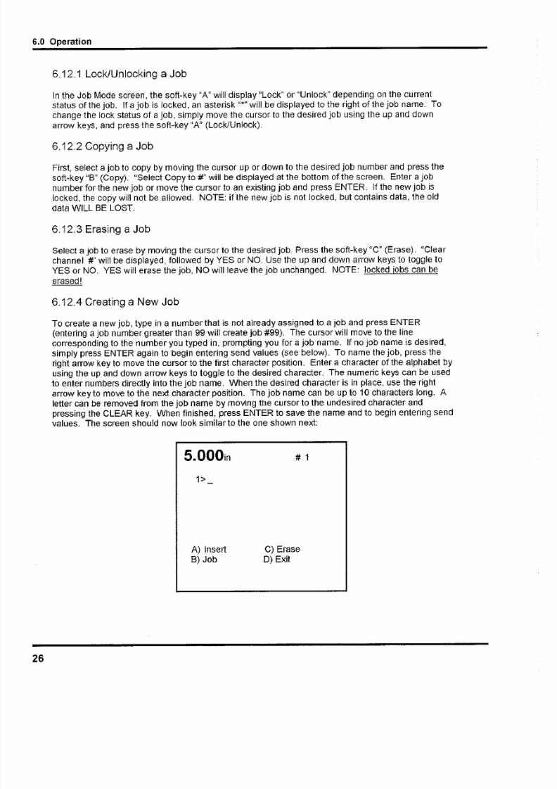
6.12.4 Creating a New Job
To create a new job, type in a number that is not already assigned to a job and press ENTER(entering a job number greater than 99 will create job #99). The cursor will move to the line
corresponding to the number you typed in, prompting you for a job name. If no job name is desired,
simply press ENTER again to begin entering send values (see below). To name the job, press the
right arrow key to move the cursor to the first character position. Enter a character of the alphabet by
using the up and down arrow keys to toggle to the desired character. The numeric keys can be used
to enter numbers directly into the job name. When the desired character is in place, use the right
arrow key to move to the next character position. The job name can be up to 10 characters long. A
letter can be removed from the job name by moving the cursor to the undesired character andpressing the CLEAR key. When finished, press ENTER to save the name and to begin entering send
values. The screen should now look similar to the one shown next:
5.000in # 1
1>
A) Insert
8) Job
C) Erase
D) Exit
26
5/13/2018 Challenge Cutter Titan 230 Operation Manual - slidepdf.com
http://slidepdf.com/reader/full/challenge-cutter-titan-230-operation-manual 27/40
6.0 Op
6.12.4.1 Entering Send Values
Now enter send values by using any of the following methods: 1) Type in the desired value and pres
ENTER, 2) Press ENTER at a blank line - this will enter the current position of the backgauge as a
send value, or 3) Use the "Cut and Record" feature as described below.
When finished entering send values you may exit the current job by pressing soft-key "S" (Job) to goback to the job mode screen or soft-key "D" (Exit) to exit to send mode. Or you may use the current
job for cutting by pressing the down arrow at the last line and following the instructions in the
"Running a Job" section (page 28).
6.12.4.2 Cut and Record
To use this feature, send the backgauge to a desired position using the backgauge glide control or b
using SEND, then make a cut. The current backgauge position will automatically be entered into the
job as a send value. This can be very convenient for setting up a program when the actual cut
positions are not known.
6.12.4.3 Channel Linking
If more than 99 cut values are needed, 2 channels can be linked together into one job providing up t
198 cut values. This is done automatically when a job is at 99 cuts and an attempt is made to add
another value. At this point, a screen is displayed asking: do you want to link to the next channel?
Use the up or down arrow key to select yes or no. If no is selected, the last cut will be discarded and
the new value will be inserted. If yes is selected, the last cut will be pushed into the first value of the
next chan nel, although it will be displayed as value 100 of the current chan nel. If the next channel is
locked, linking will not be allowed. NOTE: If the next channel is not locked, but contains data, the olddata WILL BE LOST. After 2 jobs have been linked, the linked job will be displayed as ''A/\III\I\I\IIJ\'' and
will be locked.
To unlink a job, use the up or down arrow key to point to the linked job name and press soft-key "C"
(Erase).
When finished entering send values you may exit the current job by pressing soft-key "B" (Job) to goback to the job mode screen or soft-key "D" (Exit) to exit to send mode. Or you may use the current
job for cutting by pressing the down arrow at the last line and following the instructions in the Runnin
a Programmed Job section 6.12.6 below.
6.12.5 Editing an Existing Job
6.12.5.1 Editing the Job Name
The job name can be edited (or added if an existing job does not have a name) in the job mode
screen. To edit the name, move the cursor down to the desired job number by pressing the down
arrow key. Then press the right arrow key to move the cursor to the desired character position and
edit the character by pressing the up or down arrow keys to toggle between characters of the
alphabet Numbers can be entered directly by using the number keys. Pressing CLEAR clears thecurrent character. When finished, you may either go to the current job by pressing ENTER, or go to
different job, or exit job mode.
6.12.5.2 Editing Send Values
To edit send values of an existing job, start by opening the desired job from the job mode screen. A
job is opened by one of two methods: pointing at the desired job with the cursor and pressingENTER, or by entering the job number with the keypad and pressing ENTER. Once a job has been

5/13/2018 Challenge Cutter Titan 230 Operation Manual - slidepdf.com
http://slidepdf.com/reader/full/challenge-cutter-titan-230-operation-manual 28/40
6.0 Operation
opened, the current job nurnber will be displayed in the upper right corner. Note: If the job is locked,
it cannot be edited.
Send values can now be edited by moving the cursor up or down to the desired send value and then
typing over the existing value.
When finished editing the job, you may exit the current job by pressing soft-key "8" (Job) to go backto the job mode screen or soft-key "0" (Exit) to exit to send mode. Or you may use the job for cutting
Since it is already open.
6.12.5.3 Inserting Send Values
To insert a send value, press the soft-key "A" (Insert). This moves all send values down and provides
a blank line after the current send value. If more than 99 send values are needed, the job can be
linked (see Channel Linking under the Creating a New Job section on page 26).
6.12.5.4 Erasing Send Values
To erase a send value, press the soft-key "C" (Erase). This will remove the cut value currently being
pointed to by the cursor. To backspace over the current send value without removing the line, press
the left arrow key.
6.12.6 Running a Programmed Job
To use an existing job for cutting, you must first open it by using one of two methods: move the
cursor to the desired job with the arrow keys and press ENTER, or enter the job number with the
keypad and press ENTER. Once a job has been opened, the current job number will be displayed in
the upper right corner. Now press SEND to move the backgauge to the first programmed position (or
send value). Now make a cut. Once the cut is made, the backgauge will automatically push out the
paper (if "push-out" is enabled) and move to the next programmed position. After the last cut in the
job is made, the backgauge will move to the first cut position of the current job. Pressing SEND at
any time during the job will send the backgauge to its next programmed position without making a cut.
A plus "+" sign will be displayed at the bottom of the screen if more cuts remain in the current job.
6.12.7 Exiting a Job
To exit an open job, press the soft-key "8" (Job) to return to the job mode screen, or press the soft-key "0" (Exit) to exit to the send mode screen.
6.13 A n Exam ple Job
The following is an example of how to program a job, which will be used to make two cuts: one at 8.5"
and one at 11".
1. Turn on the machine and press CLEAR to preset the backgauge. Press the soft-key "8" (Job) to
go to job mode.
2. Type in a new job number and press ENTER. Note: It must be a number that does not
correspond to an existing job. All existing jobs will be displayed on the screen (you may have to
scroll through them to see them ali). If you wish to replace an existing job with the new job, first
erase the existing job by moving the cursor to it and press the soft-key "C" (Erase). Now type in
the new number and press ENTER. In this example, job #'s 1, 2, 5, and 6 already exist. We will
use job # 7 for our new job. Press "7" and ENTER.
28
5/13/2018 Challenge Cutter Titan 230 Operation Manual - slidepdf.com
http://slidepdf.com/reader/full/challenge-cutter-titan-230-operation-manual 29/40
6.0 Op
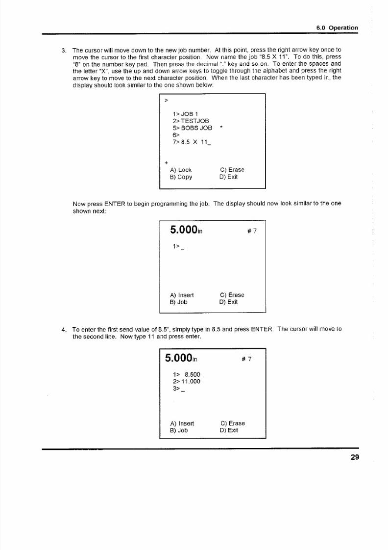
3. The cursor will move down to the new job number. At this point, press the right arrow key once
move the cursor to the first character position. Now name the job "8.5 X 11". To do this, pres
"8" on the number key pad. Then press the decimal "." key and so on. To enter the spaces anthe letter "X", use the up and down arrow keys to toggle through the alphabet and press the rig
arrow key to move to the next character position. When the last character has been typed in, th
display should look similar to the one shown below:
>
1~JOB 1
2>TESTJOB
5> BOBS JOB *
6>
7> 8.5 X 11
+
A) Lock C) Erase
8) Copy 0) Exit
Now press ENTER to begin programming the job. The display should now look similar to the on
shown next:
5.000in
1>
A) InsertB) Job
C) Erase0) Exit
#7
4. To enter the first send value of 8.5", simply type in 8.5 and press ENTER. The cursor will move
the second line. Now type 11 and press enter.
5.000in #7
1> 8.5002> 11.000
3>
A) Insert
B) Job
C) Erase
0) Exit

5/13/2018 Challenge Cutter Titan 230 Operation Manual - slidepdf.com
http://slidepdf.com/reader/full/challenge-cutter-titan-230-operation-manual 30/40
6.0 Operation
At this point, you could exit and save the job by pressing the soft-key "0" (Exit) to exit to send
mode, or the soft-key "8" (Job) to exit back to the job mode screen. However, lets use this job tocut paper.
5. Press the down arrow key once. This will remove the blank line 3 and move the cursor to the first
send value (8.5"). Now press SEND. This will move the backgauge to the 8.5" position. Place
the paper to be cut against the backgauge and press the cut buttons. Once the cut cycle iscomplete, the backgauge will push out the paper and move to the next send value (11 "). Now
position the paper again and make another cut. After the cut is made, the backgauge will push
out the stock and return to the first cut position, ready to repeat the current job.
6. Now lets lock the current job so it cannot be edited. First, exit back to job mode by pressing soft-
key "8" (Job). Now move the cursor down to the new job using the down arrow key. Now press
the soft-key "A" (Lock) to lock the job. An asterisk will appear indicating the job has been locked.
7. To exit back to send mode, press the soft-key "D" (Exit).
6.14 Operating Tips
Carefully layout each sheet before you start cutting. Find the best cut pattern to give you the mostpieces out of the sheet. If the sheet will be folded, be sure grain of the paper is running in the same
direction as the fold or you will get a rough edge on the fold.
If an accurate cut is necessary for close register work, you MUST have a sharp blade in the cutter. A
dull blade will pull or draw the paper and cause uneven cutting. Increased clamp pressure will not
eliminate draw caused by a dull knife.
The correct clamping pressure varies from paper to paper. The general rule is that you should have
enough pressure to hold the paper securely but not so much that it marks the surface of the paperexcessively. Excessive pressure causes pile distortion and inaccurate cuts.
Mark the gripper edge and the guide edge of printed paper and make sure the first cuts are with these
guide edges against the backgauge.
Measure printed paper to check for shrinkage or expansion of the paper from humidity. You may
have to disregard the printed cut lines and make your own.
When cutting business cards or narrow strips of paper, place lifts of equal height on opposite sides of
the table to prevent wear of the clamp guides.
6.15 Note to Dealer
6.15.1 Entering the Dealer Name and Phone Number
To enter or change the dealer name and phone number that will be displayed when the lubrication
alarm is displayed and when the upgrade screen is displayed, you must first enter the "Dealer Mode"
screen. To do this, turn off the power and then simultaneously hold the left and right arrow keys whileturning on the power. Continue to hold the arrow keys for a few seconds after the machine turns on.
Now enter the desired dealer information by using the up and down arrow keys to toggle through the
characters (similar to naming a job). Use the right arrow key to move to the next character and to
move to the 2nd line. When finished, turn off the power.
30

5/13/2018 Challenge Cutter Titan 230 Operation Manual - slidepdf.com
http://slidepdf.com/reader/full/challenge-cutter-titan-230-operation-manual 31/40
7.0 Knife Installation/Ch
7 .0 K n ife Ins ta lla tio n /Ch ang ing
ACAUTION Changing knives can be very dangerous unless safety precautions are
observed and extreme care is taken when handling knives.
• Make sure knife lifters are properly installed, see instructions following.
• Keep handling of unprotected knives to an absolute minimum.
• Clear off cutter table before removing knife.
• Have scabbard on cutter table and insert knife immediately.
• Warn people of any unprotected knife.
• Knife changing is a ONE PERSON OPERATION. Having more than one person trying to
change knives invites accidents.
Scabbard
Cut StickKnife Lifter
Assembly
5/16"
T-Wrench3/16" Hex
Allen
Wrench
Figure 19- Knife Changing Equipment
The knife changing equipment shown in Figure 19 is included in the cutter tool kit. The following
instructions show how to remove and install a new or re-sharpened knife. Read through these
instructions AT LEAST ONCE before attempting to actually change or install any blades.
7.1 Knife Removal
1. Make sure the knife and clamp are in the "up" position. Turn the main power switch to the "OFF
position and disconnect the machine power cord to prevent accidental power-up while serviCin
the cutter.
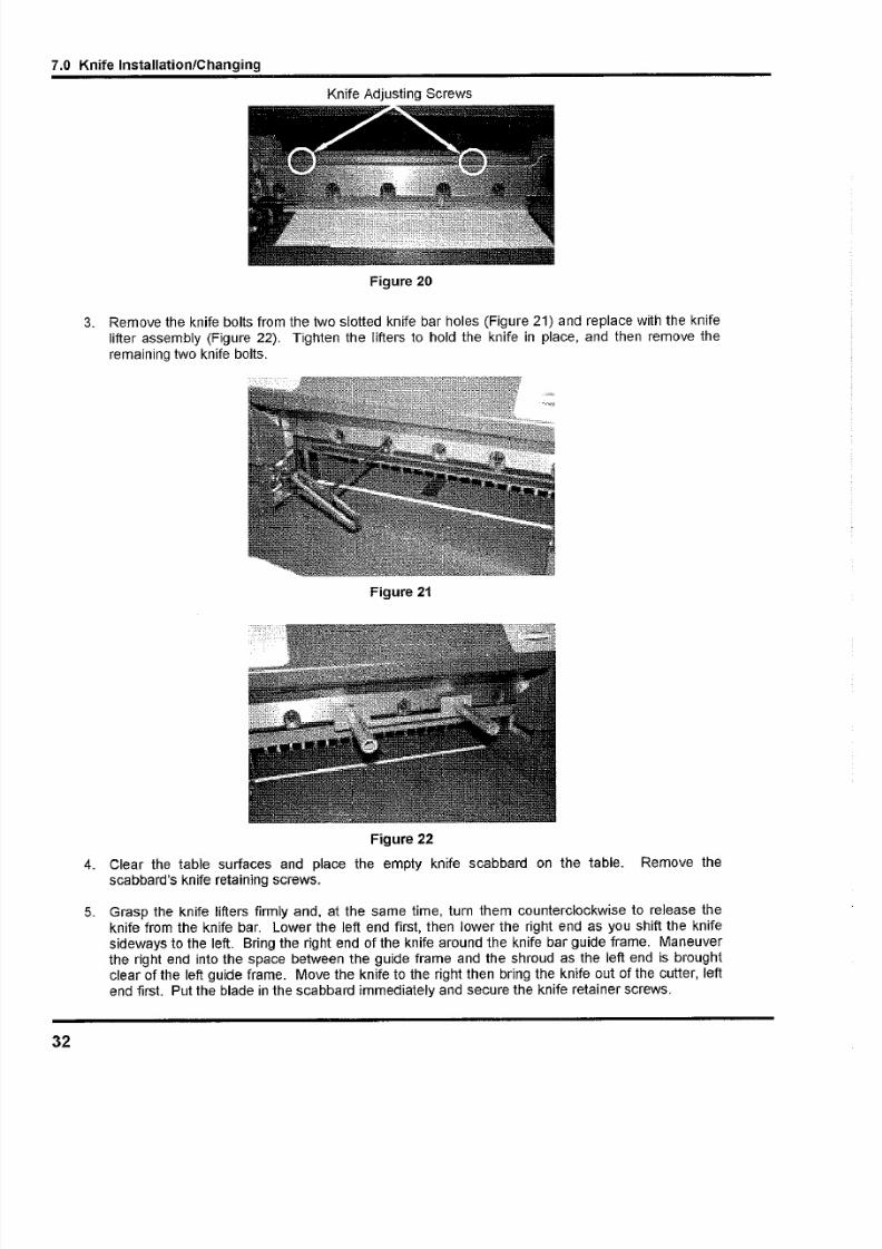
2. Back off the knife adjusting screws on top of the knife bar several turns (Figure 20). A new knif
will cut deeper than one that has been ground several times. Failure to back off the screws coul
damage the knife and/or the cutting stick.
5/13/2018 Challenge Cutter Titan 230 Operation Manual - slidepdf.com
http://slidepdf.com/reader/full/challenge-cutter-titan-230-operation-manual 32/40
7.0 Knife Installation/Changing
Knife Adjusting Screws
Figure 20
3. Remove the knife bolts from the two slotted knife bar holes (Figure 21) and replace with the knife
lifter assembly (Figure 22). Tighten the lifters to hold the knife in place, and then remove the
remaining two knife bolts.
Figure 21
Figure 22
4. Clear the table surfaces and place the empty knife scabbard on the table. Remove thescabbard's knife retaining screws.
5. Grasp the knife lifters firmly and, at the same time, turn them counterclockwise to release the
knife from the knife bar. Lower the left end first, then lower the right end as you shift the knife
sideways to the left. Bring the right end of the knife around the knife bar guide frame. Maneuver
the right end into the space between the guide frame and the shroud as the left end is broughtclear of the left guide frame. Move the knife to the right then bring the knife out of the cutter, left
end first. Put the blade in the scabbard immediately and secure the knife retainer screws.
32

5/13/2018 Challenge Cutter Titan 230 Operation Manual - slidepdf.com
http://slidepdf.com/reader/full/challenge-cutter-titan-230-operation-manual 33/40
7.0 Knife Installation/Cha
7.2 Knife Installation
ACAUTION Knives are heavy and always very sharp! Be sure to keep the edge awayfrom your body and keep other people out of the area while handling the blade. Severe lacerations o
dismemberment could result from careless handling procedures.
1. Make sure the knife and clamp are in the up position. If they are not, turn on the power using th
red and yellow main power switch, and press the CLEAR button. This will preset the backgaugeand send the knife and clamp up.
2. Turn off the machine and unplug the power cord.
3. Pull out the cutting stick using the cut stick removal tool and turn it to a new surface. If the cuttin
stick is not level or flush with the table, 1/2" strips of paper can be placed in the table slot undethe cutting stick to shim it.
4. Remove the left retainer screw from the new blade and screw the knife lifter assembly into thnew blade. Screw the lifters all the way in and then back them out a 3/4 turn).
5. Remove the other scabbard retainer screw.
6. Double check to make sure the knife adjusting screws have been backed out all the way (step #2
Knife removal). Lift the blade and insert it into the knife bar slot. Guide the blade, right edge firs
into the space between the shroud and the knife bar guide frames. Tip to clear the table sidguides, then move the left end of the blade into the knife bar slot dropping the left end as the righ
end is brought around the right knife bar guide frame and up into the knife bar slot. Raise th
knife into the knife bar slot as high as it will go and tighten the lifters.
NOTE: If the blade will not go in, either the lifters are screwed into the blade too far, or the end of th
blade is hitting the cylinder bracket at the right end of the knife slot. In this case, drop the left en
when inserting the knife.
7. Insert the knife bolts with washers and snug to hold the knife, but don't tighten them yet.
8. Remove the knife lifter assembly and replace with bolts and washers.
9. Place a few sheets of paper over the cut stick, covering the stick end-to-end.
10. Plug in the power cord and turn the power on.
11. Go to the MAINTENANCE screen and choose KNIFE ADJUST. Choose KNIFE DOWN an
press the cut buttons to send the knife to the down position (for more details on how to do thissee page 23, Knife Adjustment).
12. Turn the power off and disconnect the machine power cord.
13. Turn the knife adjusters down evenly, a little at a time, until the knife cuts through the bottom
sheet of paper the entire length of the cutting stick (Figure 23). Turning the screws down evenl
prevents uneven wear on the knife and cutting stick.

5/13/2018 Challenge Cutter Titan 230 Operation Manual - slidepdf.com
http://slidepdf.com/reader/full/challenge-cutter-titan-230-operation-manual 34/40
7.0 Knife Installation/Changing
Figure 23
14. Plug in the power cord and turn the power on.
15. Press CLEAR. This will raise the knife and clamp to the up position.
16. Turn the power off and disconnect the machine power cord.
17. Tighten all knife bolts securely.
18. Plug in the power cord and turn the power on. Make a test cut through a full lift of paper and
make minor adjustments if necessary by repeating steps 9 through 17. NOTE: If the knife ends
cut but the middle doesn't, you could have dips or uneven spots in the knife and/or cutting stick.
These can be eliminated by placing 1/2" strips of paper in the table slot beneath the cutting stick
to shim it.
19. Send the dull knife to a knife grinder. Do not attempt to sharpen your own knives! See the Knife
Care Tips Section below to determine the knife bevel angle.
7.3 Knife Care Tips
ACAUTION ! KNIFE SAFETY! Knives are DANGEROUS!!! They are heavy and very
sharp, even after use. Keep the edge away from your body and keep the area clear of others when
handling knives. Never touch the cutting edge! To prevent personal injury and damage to the knife,
always keep knives in their holders with screws tightened. You are aware of the dangers, but others
may not be. Never attempt to hone, polish, or service the knife in any way. Failure to follow safety
procedures may result in severe lacerations or dismemberment.
7.3.1 Knife Blade Life
Knife blade life, or the time between sharpenings, can be affected by many factors. One important
factor is the type of paper being cut. Abrasive paper, such as recycled paper, soft paper such as
newsprint paper, and bound books can all significantly shorten knife blade life. Also, if the knife depthis set too deep, the knife will cut too deep into the cutting stick and can dull the knife blade.
A knife can last between 2,000 and 5,000 cuts before it needs to be sharpened. Cutting soft paper
(such as newsprint paper) or paper with high post-consumer recycled content can cause the knife to
need sharpening after only 2,000 to 3,000 cuts. Cutting pure paper, such as bond paper with no
recycled content, or hard paper can allow the knife to be used for as many as 5,000 cuts before it
needs to be sharpened. In all cases, the operator should continually check the quality of the cut to
34
5/13/2018 Challenge Cutter Titan 230 Operation Manual - slidepdf.com
http://slidepdf.com/reader/full/challenge-cutter-titan-230-operation-manual 35/40
7.0 Knife Installation/Cha
determine when the knife blade needs to be sharpened. Some characteristics that indicate a blade
needs sharpening are:
• The knife hesitates or stalls while making a cut.
• The sheets are not all cut to the same length (usually the top few sheets are longer than the
rest of the sheets" this is sometimes called "draw").
• Cut marks appear on the cut face of the paper.
• The profile of the cut (side view) is not perpendicular to the table.
• The cut does not appear straight when viewed from the top.
• The knife makes a "rougher" sound as it passes through paper.
• Nicks are visible on the cutting edge of the knife.
7.3.2 Cutting Stick
A worn cutting stick can affect the cut quality of the bottom sheets. When this happens, the cut stickcan be rotated. Usually, the stick should be rotated one or two times between knife sharpenings.
There are 8 possible cut stick positions. The stick can be rotated 4 times, and then turned end to
end, and rotated 4 times again.
7.3.3 Bevel Angle
Challenge recommends that bevel angles for the Titan 230 knives be in the range of 21 0 to 23°. In
general, a 21 c bevel angle will provide better cut quality when cutting soft paper (such as newsprint),
recycled paper, or bou nd books. However, 21 ° angle knives can become dull sooner than 23° knives
which results in shorter knife blade life. A knife with a 23° bevel angle, on the other hand, will not dul
as easily, and can provide satisfactory results when cutting most types of paper. Knives shipped with
the Titan 230 from the factory have a bevel angle of 23°.
7.3.4 Helpful Suggestions
• If your establishment is large enough to purchase more than one set of knives, have one set
beveled at 210 and the other at 23°. Note: A set consists of 3 knives: one in the machine,
one as a back up, and one at the grinder.
• If the machine seems to strain but the cut quality is still good, reduce the pile height. Youmay also carefully apply glycerin to the bevel when cutting hard, coated paper. Tie a cloth to
the end of a stick; dip the stick in glycerin, and apply. Never apply by hand' In lieu of
glycerin you may lightly rub white bar soap along the bevel. Lubrication will prolong the life o
your machine and reduce maintenance.
7.3.5 Knife Care
• To prevent corrosion, knives are coated with light oil. It should be REMOVED WITH CARE.
• While removing or installing a knife, be careful not to allow the edge to bump against the
machine. Nicks will result.

5/13/2018 Challenge Cutter Titan 230 Operation Manual - slidepdf.com
http://slidepdf.com/reader/full/challenge-cutter-titan-230-operation-manual 36/40
7.0 Knife Installation/Changing
• If a knife bolt is damaged, replace it.
• Always keep knife bolts securely tightened.
• Always use the heavy duty knife bolt washers provided by Challenge. Failure to do so could
result in scratching or marring of the clamp face.
• Store knives in a dry environment to prevent corrosion.
• Never attempt to service a knife in any way.
36
5/13/2018 Challenge Cutter Titan 230 Operation Manual - slidepdf.com
http://slidepdf.com/reader/full/challenge-cutter-titan-230-operation-manual 37/40
8.0 Titan 230 Flo
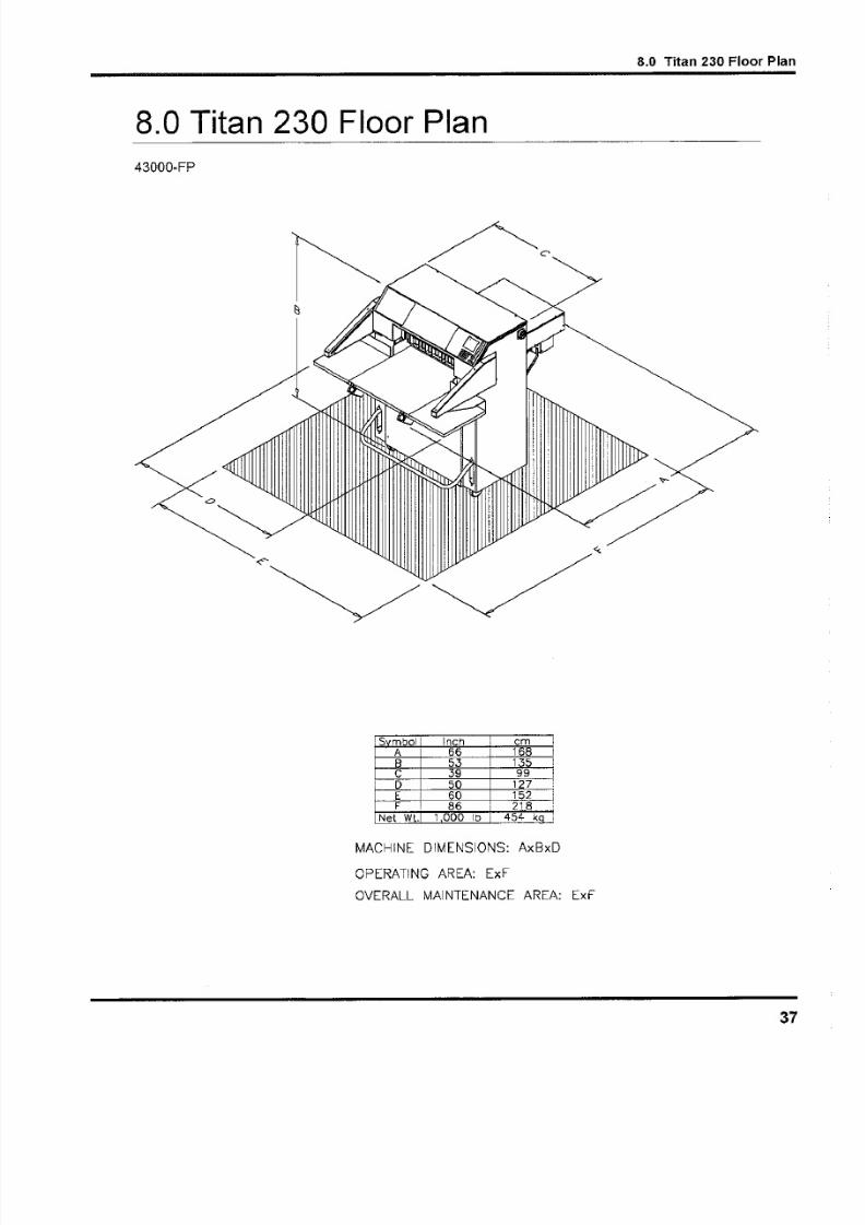
8.0 Titan 230 Floor Plan
43000-FP
II
ISymbol Inch I em II A 66 168 I
I 8 53 135!I C 39 99,I D 50 127:
L _ EF I 60 152__j1-?~--~8~6~~~2~18 1
I Net WL 1 000 Ib 454 kq I
MACH INE D IMENSIO NS: AxB xD
OPERATING AREA: ExF
OVERALL MAINTENANCE AREA: ExF

5/13/2018 Challenge Cutter Titan 230 Operation Manual - slidepdf.com
http://slidepdf.com/reader/full/challenge-cutter-titan-230-operation-manual 38/40
Machine manufacturer CHALLENGE Model TITAN 230
9.0 Safety Systems Test
9.0 Safety Systems Test
Serial Number _
Frequency of test: THESE TESTS SHOULD BE PERFORMED AT THE BEGINNING OF EACH
WORK DAY.
Turn the power on and press CLEAR to preset the backgauge. Make sure the knife and clamp are in
the up position (if they are not, follow the instructions in this manual to send them up).
Test #1: Wave a test object 12mm in diameter between the electric eye beams. The indicator lights
should indicate the eyes are blocked. If they do not, do not use the machine. Repair or adjustment is
needed.
Test #2: While making a cut, lean into the electric eye beams. The knife and clamp should
immediately return to the up position. If they do not, do not use the machine. Repair or adjustment is
needed.
38

5/13/2018 Challenge Cutter Titan 230 Operation Manual - slidepdf.com
http://slidepdf.com/reader/full/challenge-cutter-titan-230-operation-manual 39/40
9.0 Safety System
Date
Please enter date and initials for both tests.
Test 1
Test 2
Date
Test 1
Test 2
Date
Test 1
Test 2
Date
Test 1
Test 2
Date
Test 1
Test 2
Repairs Date
Initials of
Repairer

5/13/2018 Challenge Cutter Titan 230 Operation Manual - slidepdf.com
http://slidepdf.com/reader/full/challenge-cutter-titan-230-operation-manual 40/40