Embed Size (px)
DESCRIPTION
CHANTI update. F. Ambrosino, T. Capussela , D. Di Filippo, P. Massarotti, M. Mirra, M. Napolitano, L. Roscilli , G. S aracino. Outlook. Construction & installation CHANTI-FE boards calibration and tests ToT boards calibration and tests Progress on DCS Commissioning schedule - PowerPoint PPT Presentation
Citation preview
CHANTI update
F. Ambrosino, T. Capussela, D. Di Filippo, P. Massarotti, M. Mirra, M. Napolitano, L. Roscilli, G. Saracino
Outlook
• Construction & installation• CHANTI-FE boards calibration and tests• ToT boards calibration and tests• Progress on DCS• Commissioning schedule• To do list• Conclusions
Construction
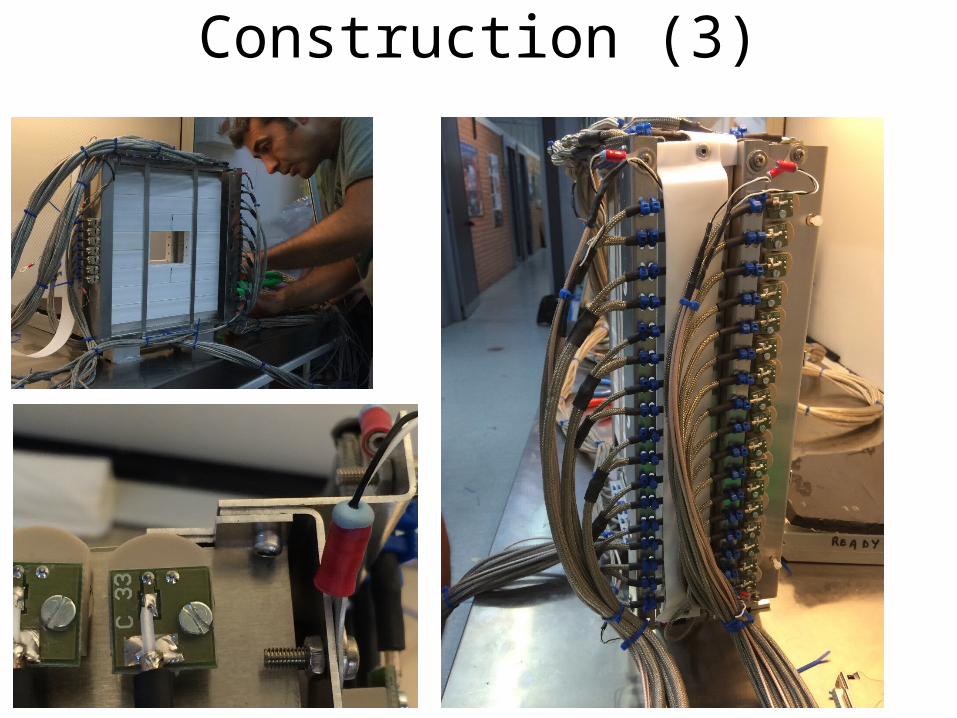
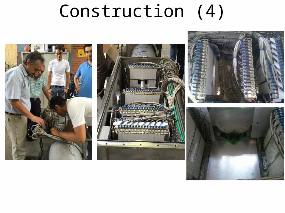
• All of the six stations have been fully assembled and cabled
• All of the 300 SiPMs have been tested for funtionality. A subset (25%) tested at diferent temperatures to compare temperature behaviour wrt Hamamatsu specs
• All of the connections with SiPMs and Pt100 probes checked before assembly
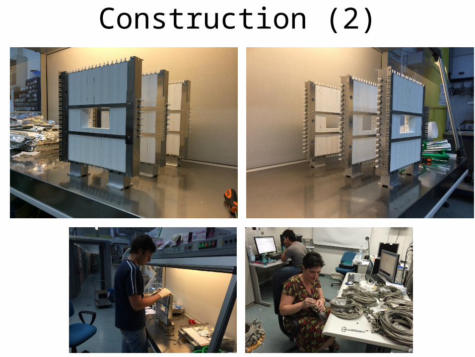
Construction (2)
Construction (3)
Construction (4)
Installation
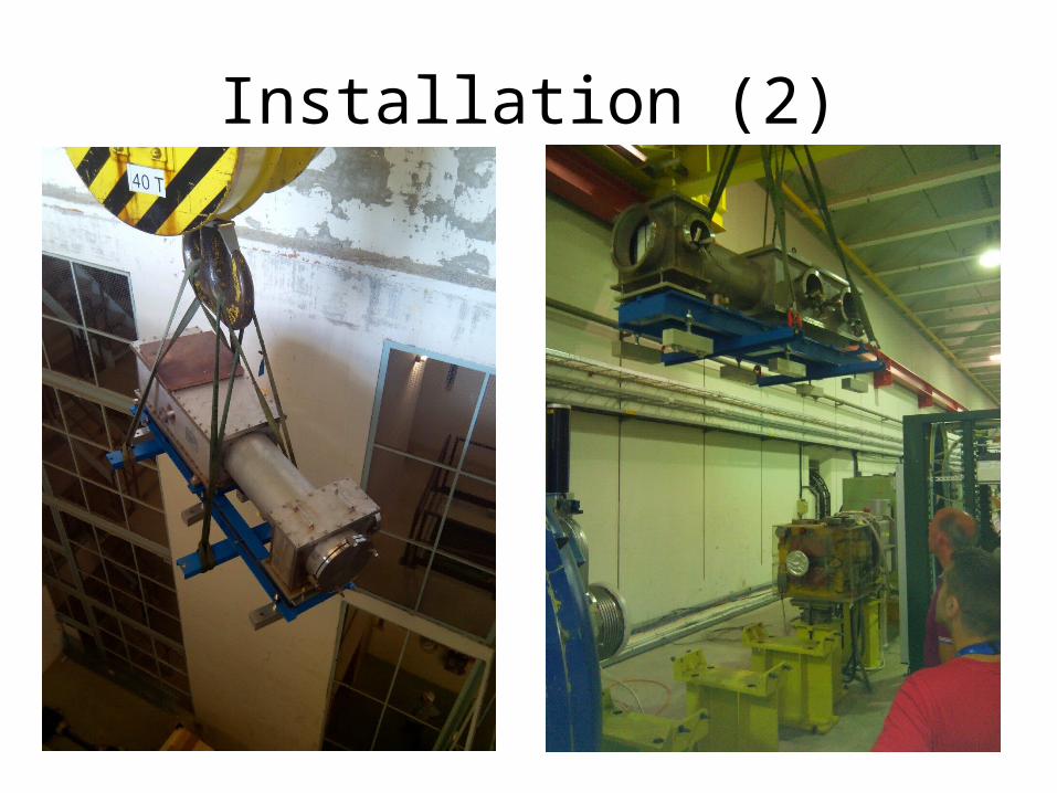
• CHANTI stations aligned in Napoli to +- 0,5 mm. The last CHANTI station has adjustable feet to this aim.
• Check of alignment re-done at CERN after transportation.
• Installation on the beam line and survey successful.
Installation (2)
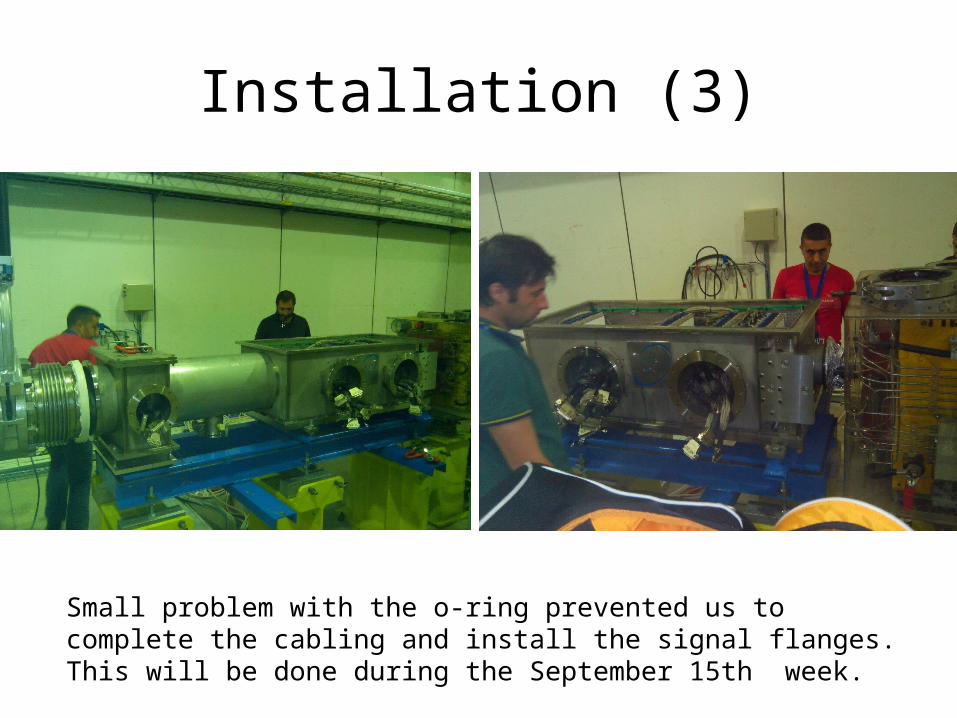
Installation (3)
Small problem with the o-ring prevented us to complete the cabling and install the signal flanges. This will be done during the September 15th week.
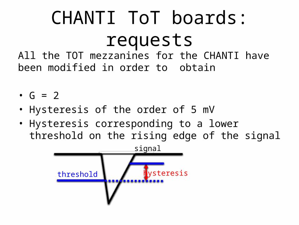
CHANTI ToT boards: requestsAll the TOT mezzanines for the CHANTI have been modified in order to obtain
• G = 2• Hysteresis of the order of 5 mV• Hysteresis corresponding to a lower threshold on the rising
edge of the signalsignal
threshold hysteresis
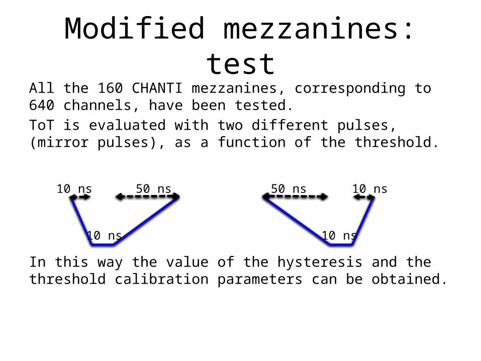
Modified mezzanines: testAll the 160 CHANTI mezzanines, corresponding to 640 channels, have been tested.ToT is evaluated with two different pulses, (mirror pulses), as a function of the threshold.
In this way the value of the hysteresis and the threshold calibration parameters can be obtained.
50 ns 10 ns
10 ns
50 ns10 ns
10 ns
Hyst(mv)
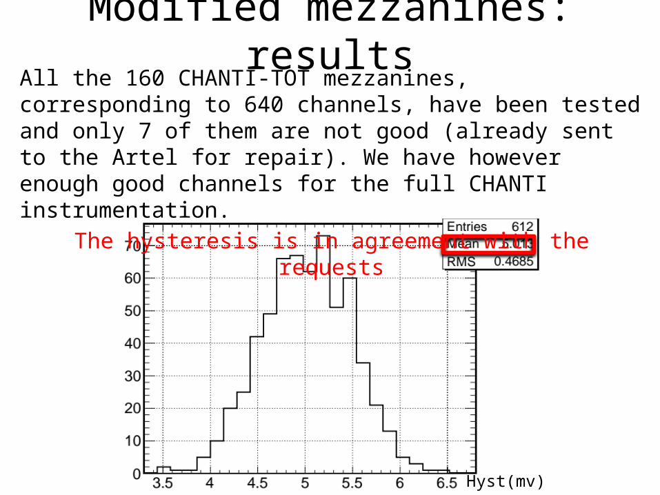
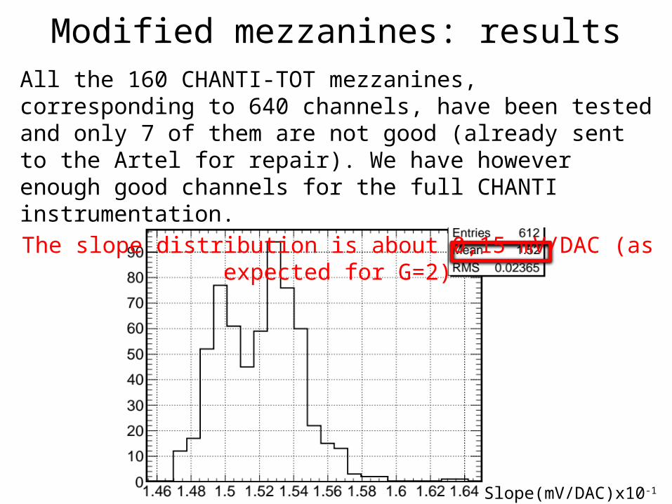
Modified mezzanines: resultsAll the 160 CHANTI-TOT mezzanines, corresponding to 640 channels, have been tested and only 7 of them are not good (already sent to the Artel for repair). We have however enough good channels for the full CHANTI instrumentation.
The hysteresis is in agreement with the requests
Slope(mV/DAC)x10-1
All the 160 CHANTI-TOT mezzanines, corresponding to 640 channels, have been tested and only 7 of them are not good (already sent to the Artel for repair). We have however enough good channels for the full CHANTI instrumentation.
The slope distribution is about 0,15 mV/DAC (as expected for G=2)
Modified mezzanines: results
Modified mezzanines: results
Offset(mV)
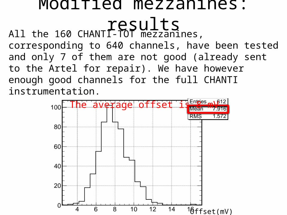
All the 160 CHANTI-TOT mezzanines, corresponding to 640 channels, have been tested and only 7 of them are not good (already sent to the Artel for repair). We have however enough good channels for the full CHANTI instrumentation.
The average offset is 8 mV
CHANTI-FE CALIBRATION
MUX32 X
CHANTI-FE
Keithley picoAmperometer
Calibrated high impedence resistor
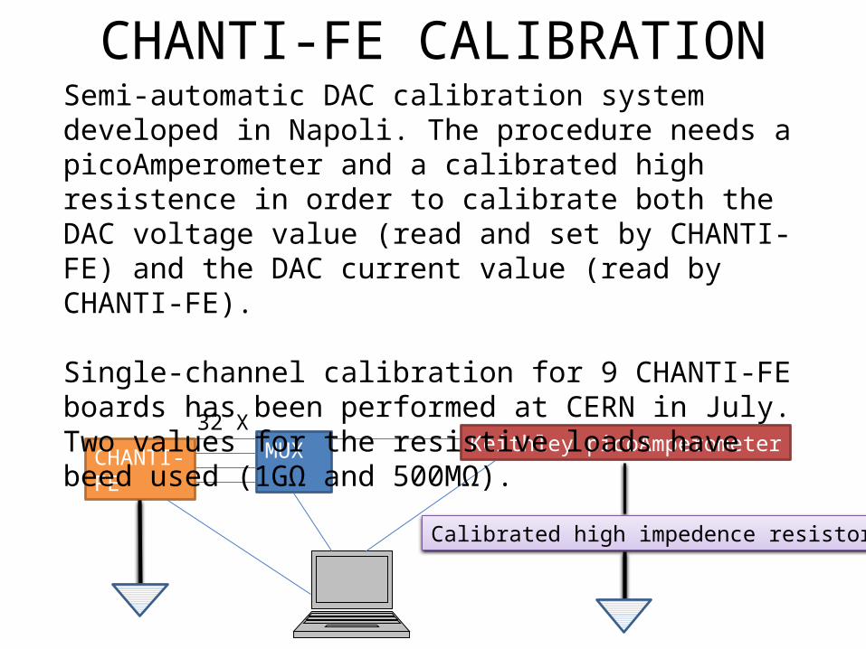
Semi-automatic DAC calibration system developed in Napoli. The procedure needs a picoAmperometer and a calibrated high resistence in order to calibrate both the DAC voltage value (read and set by CHANTI-FE) and the DAC current value (read by CHANTI-FE).
Single-channel calibration for 9 CHANTI-FE boards has been performed at CERN in July. Two values for the resistive loads have beed used (1GΩ and 500MΩ).
DAC value
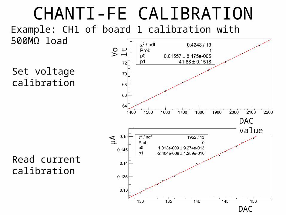
CHANTI-FE CALIBRATIONExample: CH1 of board 1 calibration with 500MΩ load
Volt
DAC valueμA
Set voltage calibration
Read current calibration
CHANTI-FE CALIBRATION
#CH
Volta
ge S
lope
(Vol
t/DA
C)
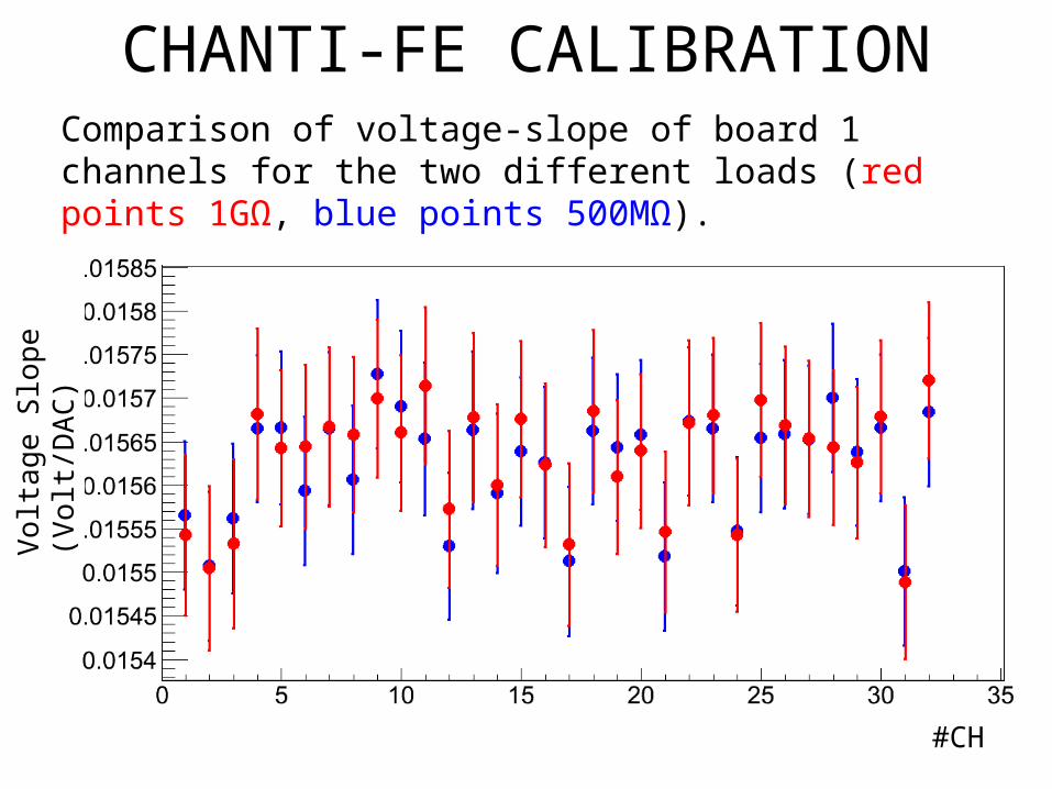
Comparison of voltage-slope of board 1 channels for the two different loads (red points 1GΩ, blue points 500MΩ).
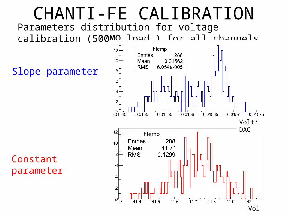
CHANTI-FE CALIBRATIONParameters distribution for voltage calibration (500MΩ load ) for all channels
Volt/DAC
Volt
Slope parameter
Constant parameter
CHANTI-FE CALIBRATION
Keithley Source VoltageCurrent Meter
MUX
32 XBoard containing SiPM
CHANTI-FE
Keithley Current Meter
MUX32 X
Board containing SiPM
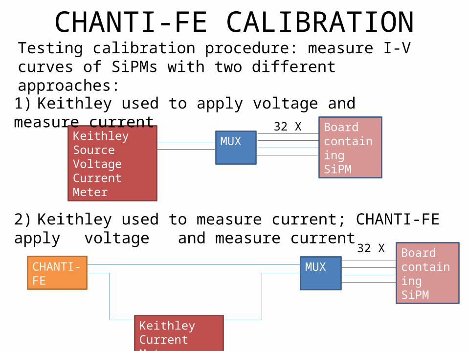
Testing calibration procedure: measure I-V curves of SiPMs with two different approaches:
1) Keithley used to apply voltage and measure current
2) Keithley used to measure current; CHANTI-FE apply voltage and measure current
Volt
CHANTI-FE CALIBRATION
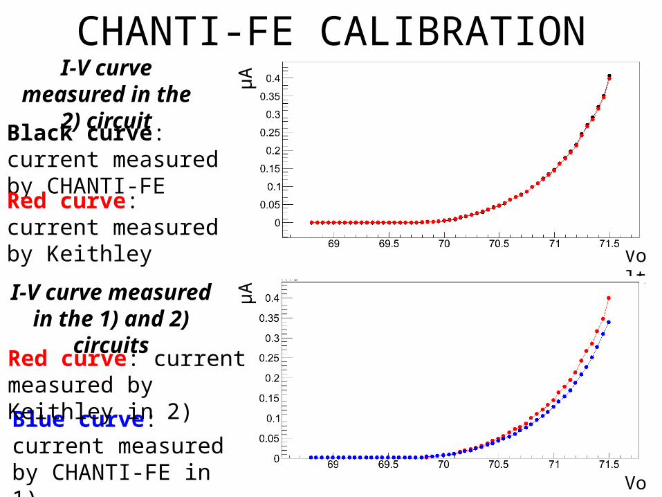
Black curve: current measured by CHANTI-FE
Red curve: current measured by Keithley
I-V curve measured in the 2) circuit μA
Volt
μAI-V curve measured in the 1) and 2) circuits
Blue curve: current measured by CHANTI-FE in 1)
Red curve: current measured by Keithley in 2)
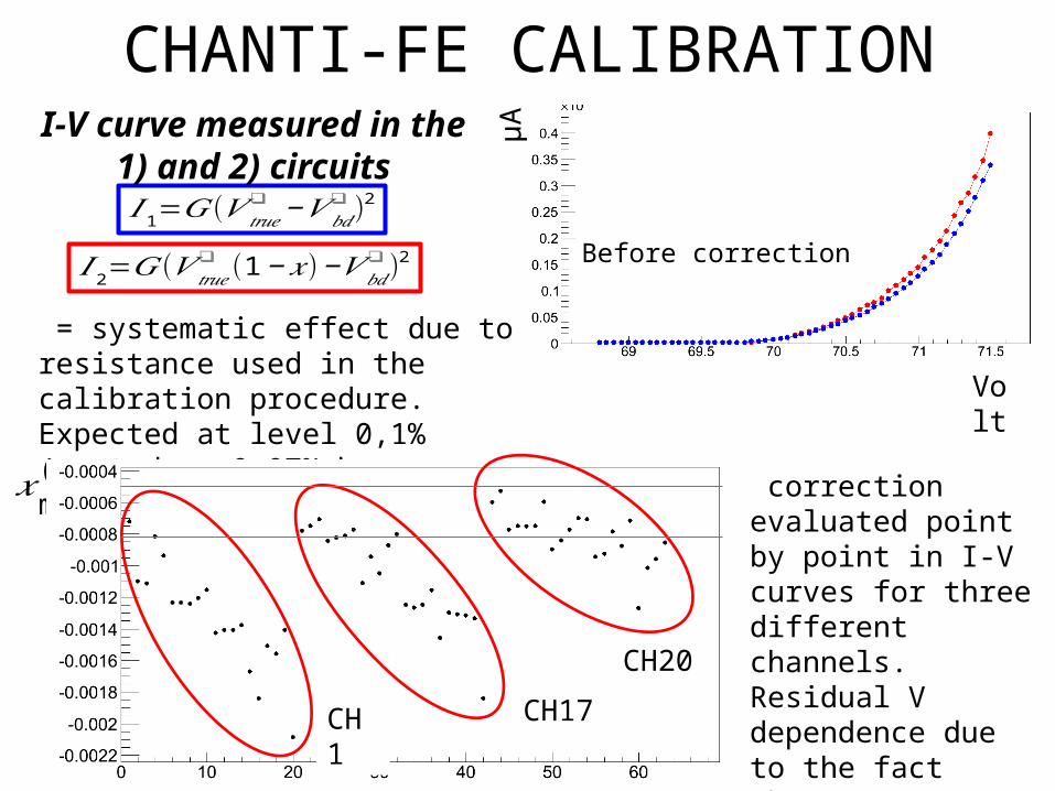
𝐼 1=𝐺(𝑉 𝑡𝑟𝑢𝑒❑ −𝑉 𝑏𝑑
❑ )2
𝐼 2=𝐺(𝑉 𝑡𝑟𝑢𝑒❑ (1−𝑥)−𝑉 𝑏𝑑
❑ )2
I-V curve measured in the 1) and 2) circuits
CHANTI-FE CALIBRATION
= systematic effect due to resistance used in the calibration procedure. Expected at level 0,1% (quoted ± 0,07% by manufacturer)
Volt
μA𝑥 correction evaluated
point by point in I-V curves for three different channels. Residual V dependence due to the fact that I-V curve is not really quadratic. CH1 CH17
CH20
Before correction
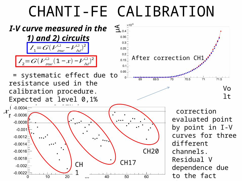
𝐼 1=𝐺(𝑉 𝑡𝑟𝑢𝑒❑ −𝑉 𝑏𝑑
❑ )2
𝐼 2=𝐺(𝑉 𝑡𝑟𝑢𝑒❑ (1−𝑥)−𝑉 𝑏𝑑
❑ )2
I-V curve measured in the 1) and 2) circuits
CHANTI-FE CALIBRATION
= systematic effect due to resistance used in the calibration procedure. Expected at level 0,1% (quoted ± 0,07% by manufacturer)
Volt
μA𝑥 correction evaluated
point by point in I-V curves for three different channels. Residual V dependence due to the fact that I-V curve is not really quadratic. CH1 CH17
CH20
After correction CH1
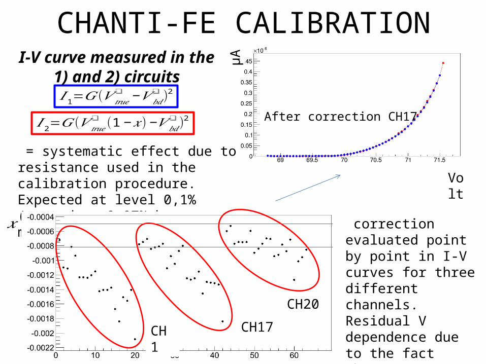
𝐼 1=𝐺(𝑉 𝑡𝑟𝑢𝑒❑ −𝑉 𝑏𝑑
❑ )2
𝐼 2=𝐺(𝑉 𝑡𝑟𝑢𝑒❑ (1−𝑥)−𝑉 𝑏𝑑
❑ )2
I-V curve measured in the 1) and 2) circuits
CHANTI-FE CALIBRATION
= systematic effect due to resistance used in the calibration procedure. Expected at level 0,1% (quoted ± 0,07% by manufacturer)
Volt
μA𝑥 correction evaluated
point by point in I-V curves for three different channels. Residual V dependence due to the fact that I-V curve is not really quadratic. CH1 CH17
CH20
After correction CH17
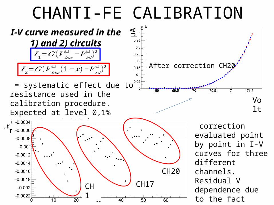
𝐼 1=𝐺(𝑉 𝑡𝑟𝑢𝑒❑ −𝑉 𝑏𝑑
❑ )2
𝐼 2=𝐺(𝑉 𝑡𝑟𝑢𝑒❑ (1−𝑥)−𝑉 𝑏𝑑
❑ )2
I-V curve measured in the 1) and 2) circuits
CHANTI-FE CALIBRATION
= systematic effect due to resistance used in the calibration procedure. Expected at level 0,1% (quoted ± 0,07% by manufacturer)
Volt
μA𝑥 correction evaluated
point by point in I-V curves for three different channels. Residual V dependence due to the fact that I-V curve is not really quadratic. CH1 CH17
CH20
After correction CH20
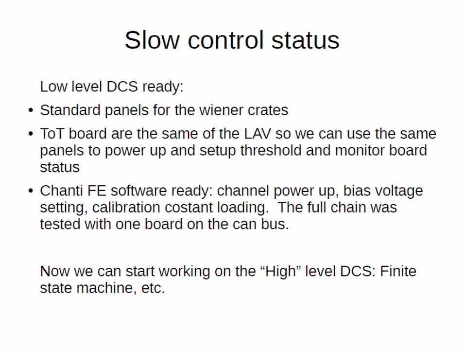
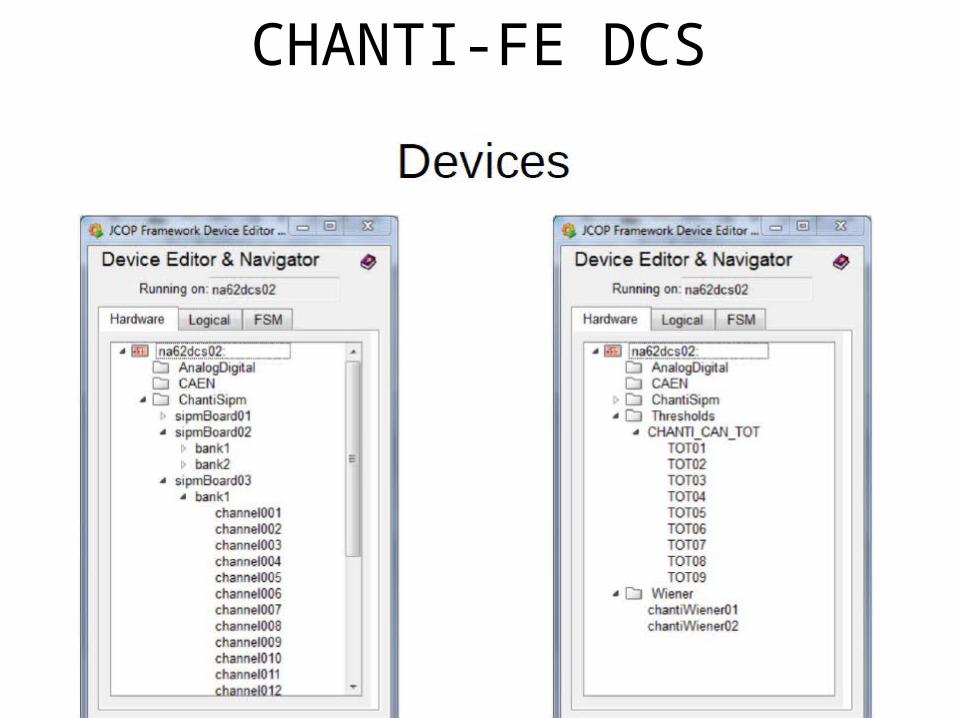
CHANTI-FE DCS
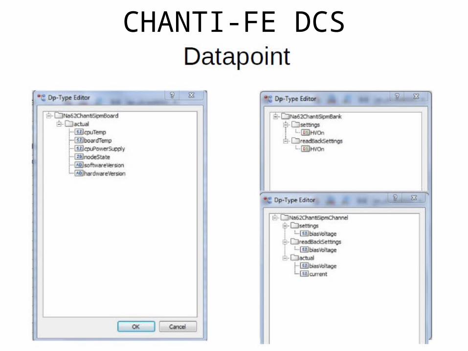
CHANTI-FE DCS
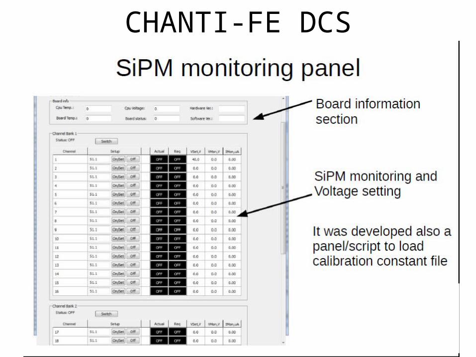
CHANTI-FE DCS
Commissioning schedule
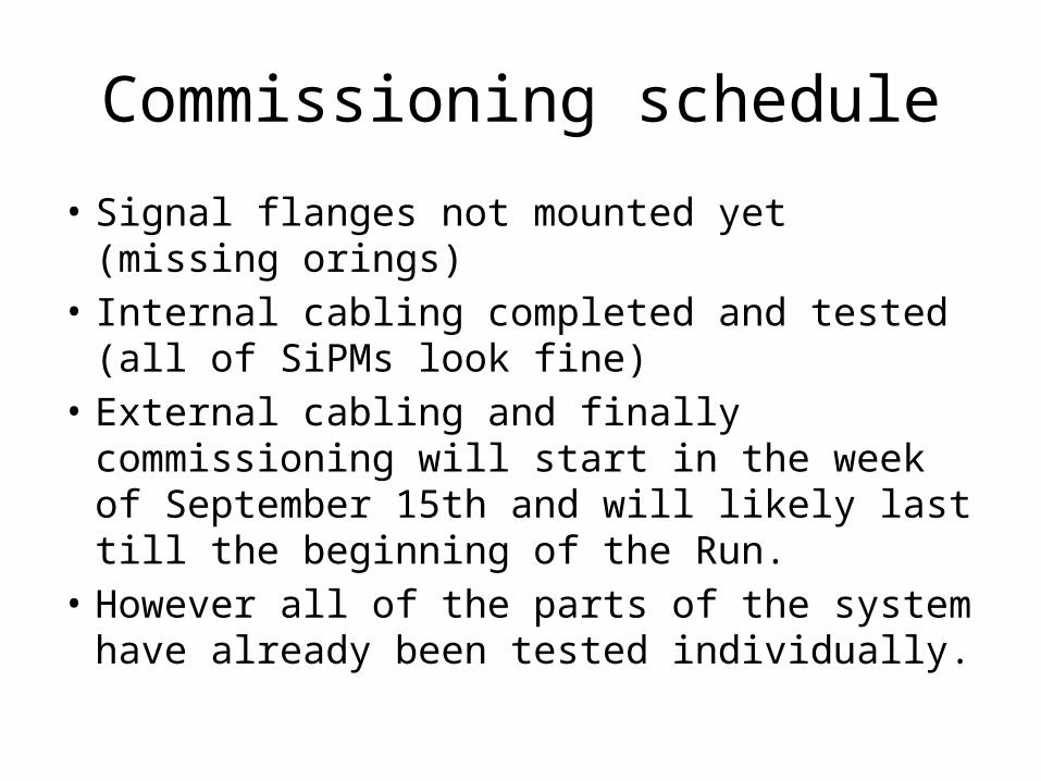
• Signal flanges not mounted yet (missing orings) • Internal cabling completed and tested (all of
SiPMs look fine)• External cabling and finally commissioning will
start in the week of September 15th and will likely last till the beginning of the Run.
• However all of the parts of the system have already been tested individually.

To do list
• Upgrade of digitization and reconstruction on MC (deadline: few months ago actually…but not enough manpower up to now)
• Raw data definition and L1/L2 sw (deadline: end of September)
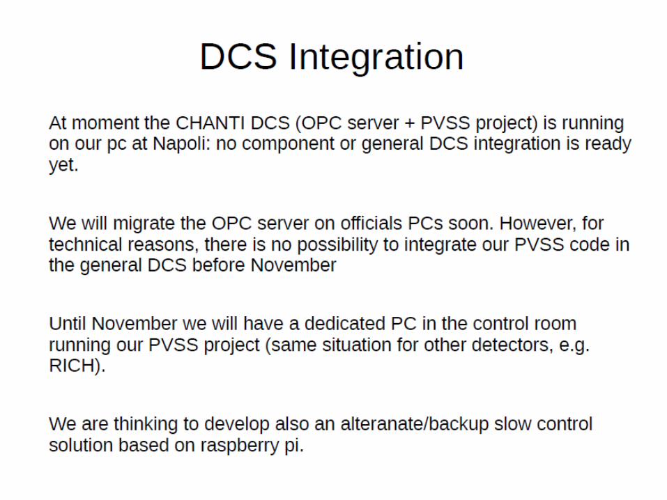
• Completion of DCS and inclusion in general framework (deadline: November)
Conclusions
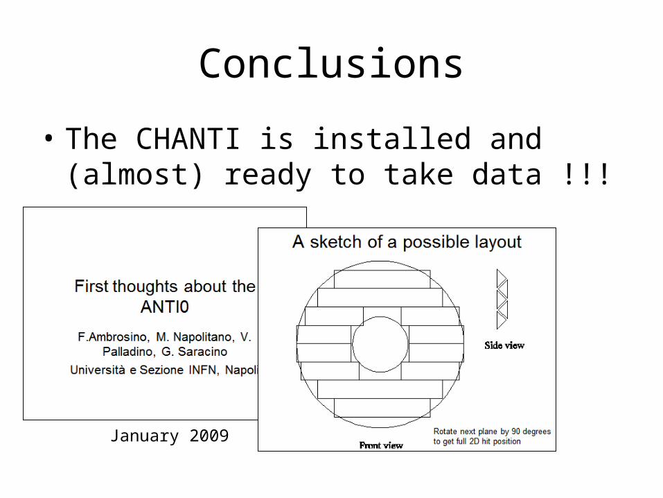
• The CHANTI is installed and (almost) ready to take data !!!
January 2009


![Quarterly Update [Company Update]](https://img.pdfslide.net/doc/110x75/577cb49b1a28aba7118c9348/quarterly-update-company-update.jpg)


![Information Update [Company Update]](https://img.pdfslide.net/doc/110x75/577c7bd21a28abe054987811/information-update-company-update.jpg)


![Earnings Update [Company Update]](https://img.pdfslide.net/doc/110x75/577c7f491a28abe054a3eab4/earnings-update-company-update.jpg)
![Company Update [Company Update]](https://img.pdfslide.net/doc/110x75/577c982f1a28ab163a8b480c/company-update-company-update.jpg)
