Embed Size (px)
Citation preview
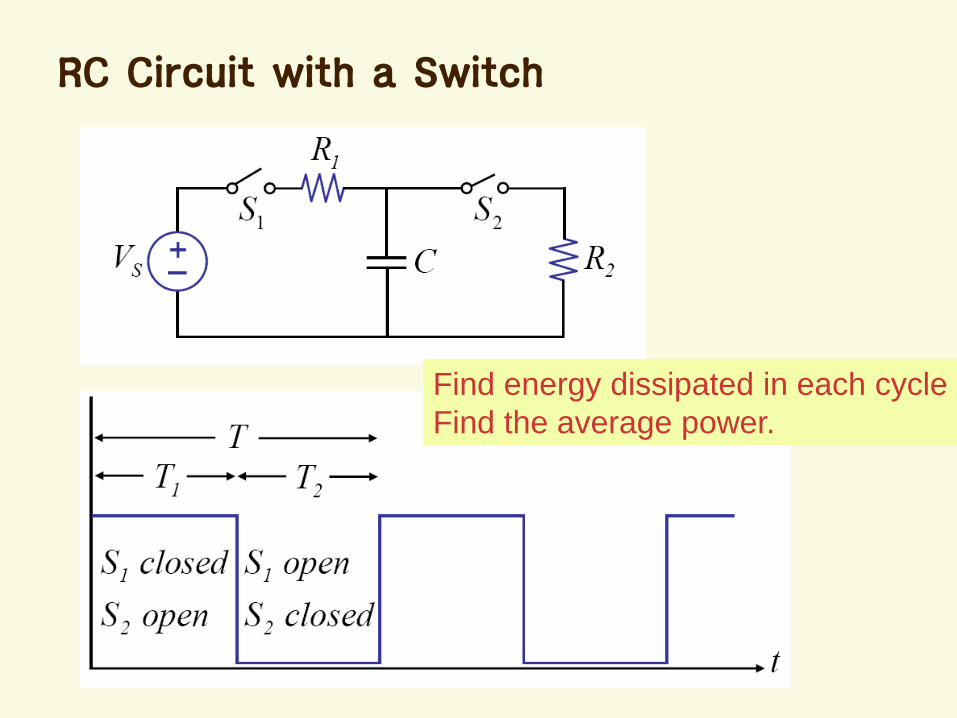
Chap. 11 Energy and Power in
Digital Circuits
Average Power in an RC Circuit
Power Dissipation in Logic Gates
CMOS Logic
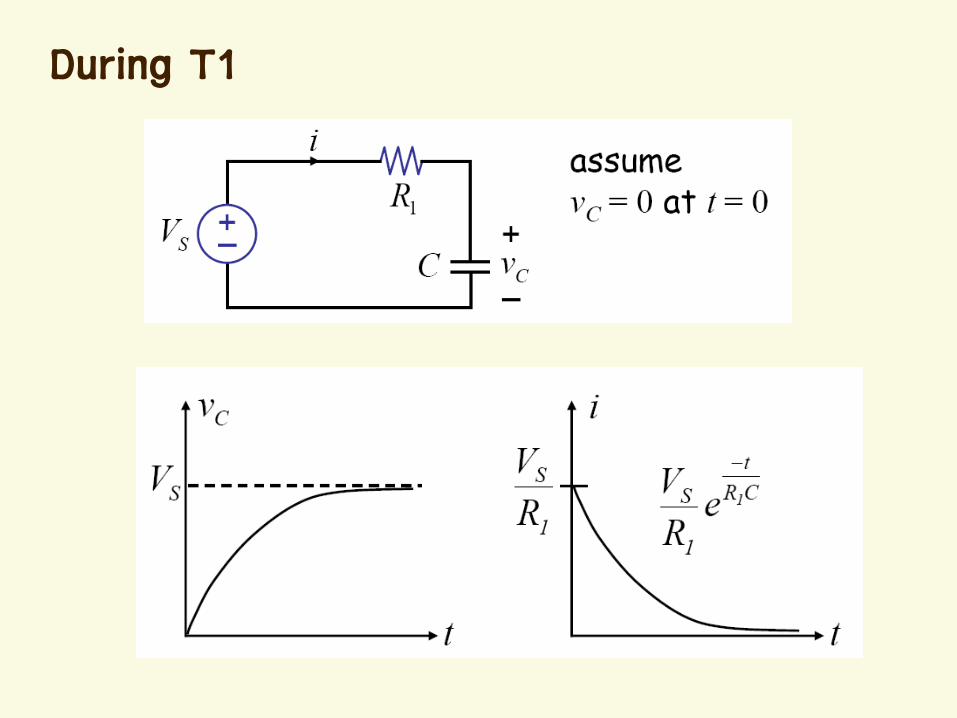
RC Circuit with a Switch
Find energy dissipated in each cycle
Find the average power.
During T1
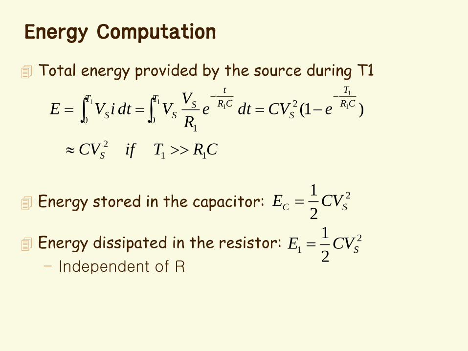
Energy Computation
Total energy provided by the source during T1
Energy stored in the capacitor:
Energy dissipated in the resistor:
– Independent of R
CRTifCV
eCVdteR
VVdtiVE
S
CR
T
S
TCR
t
SS
T
S
11
2
2
01
0)1( 1
1
11
1
2
2
1SC CVE
2
12
1SCVE
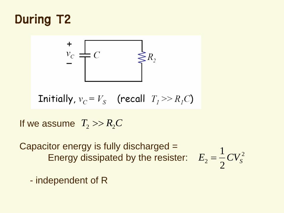
During T2
If we assume
Capacitor energy is fully discharged =
Energy dissipated by the resister:
- independent of R
CRT 22
2
22
1SCVE
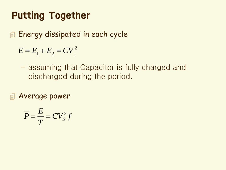
Putting Together
Energy dissipated in each cycle
– assuming that Capacitor is fully charged and discharged during the period.
Average power
2
21 SCVEEE
fCVT
EP S
2
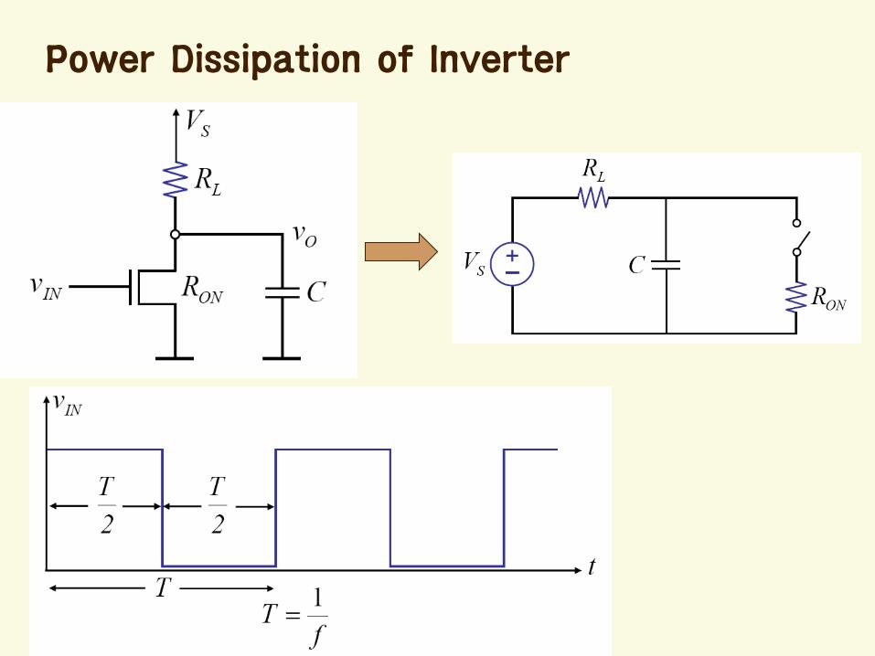
Power Dissipation of Inverter
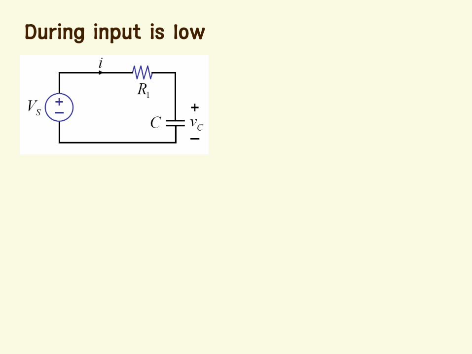
During input is low
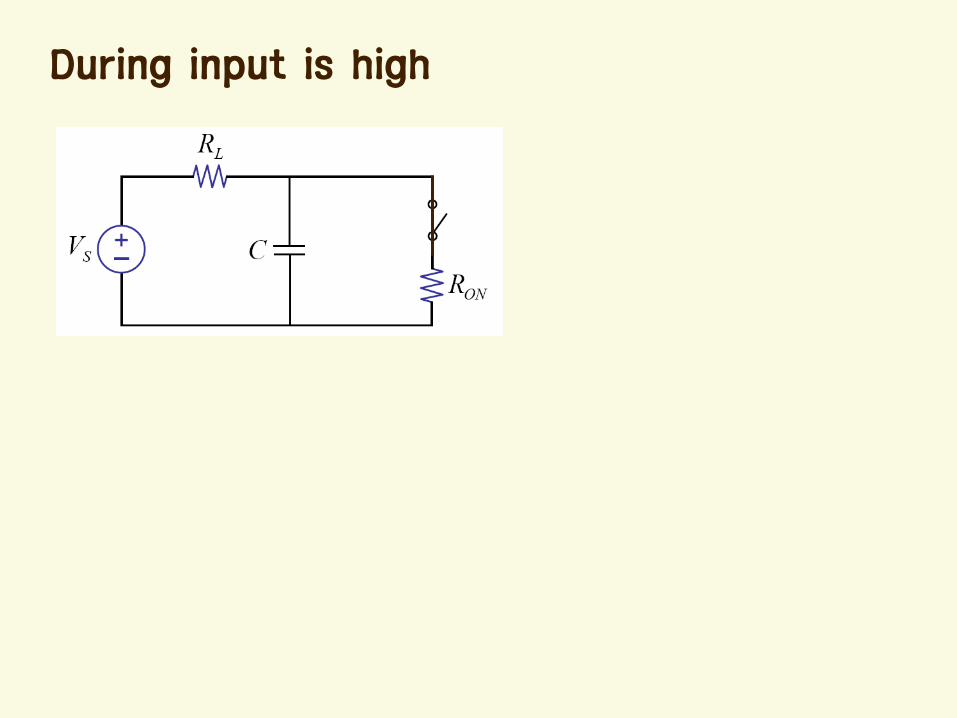
During input is high
Easy way to solve
Average power = static power + dynamic power
– Static power: independent of the frequency
– Dynamic power: charging-and-discharging of the capacitor
Average Power
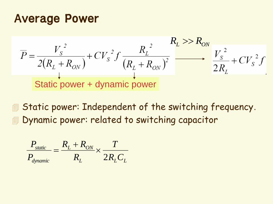
Static power + dynamic power
Static power: Independent of the switching frequency.
Dynamic power: related to switching capacitor
ONL RR
LLL
ONL
dynamic
static
CR
T
R
RR
P
P
2
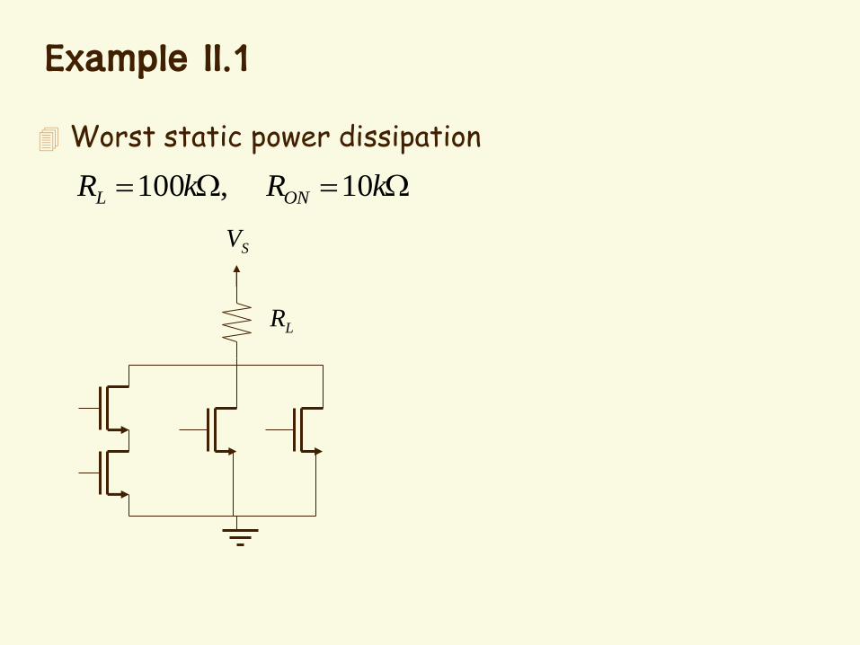
Example II.1
kRkR ONL 10,100
Worst static power dissipation
LR
SV
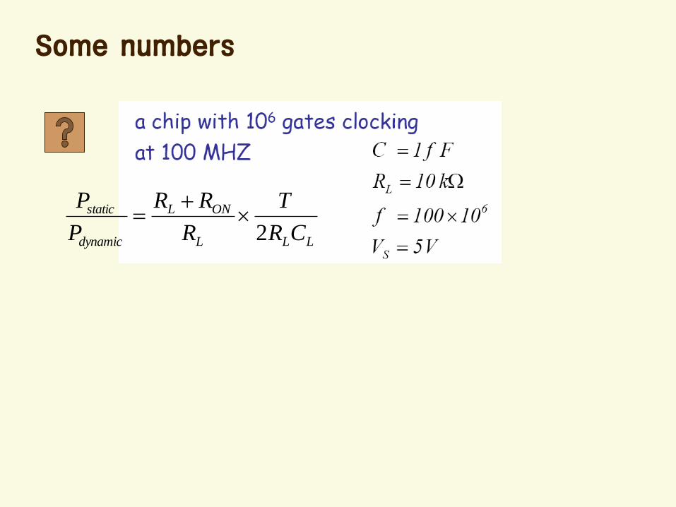
Some numbers
LLL
ONL
dynamic
static
CR
T
R
RR
P
P
2
Power Minimization
Dynamic power
– Reduce the supply voltage (5V -> 1.5V)• Change the voltage on need
– Reduce the capacitance
– Reduce the frequency• Turn off clock when not in use
Static power
– CMOS logic
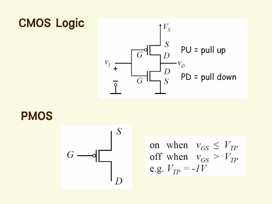
PMOS
CMOS Logic
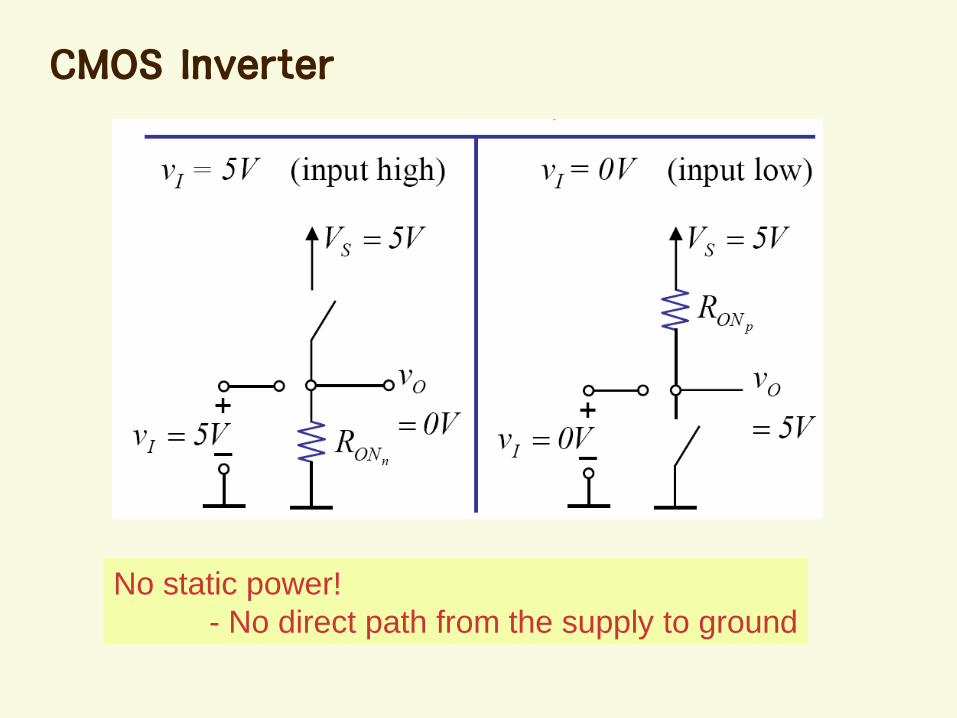
CMOS Inverter
No static power!
- No direct path from the supply to ground

Dynamic Power of CMOS
fCVP S
2
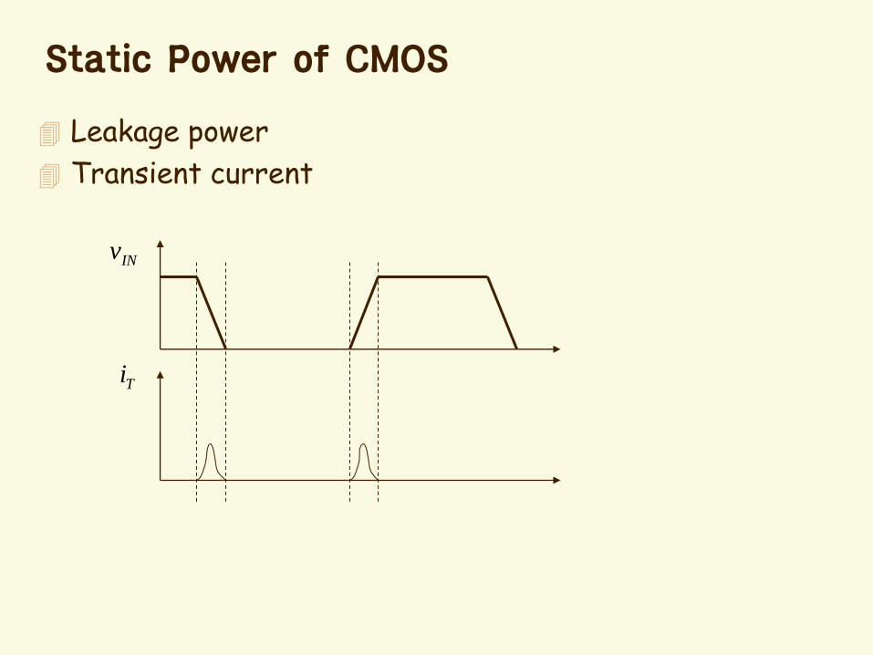
Static Power of CMOS
Leakage power
Transient current
INv
Ti
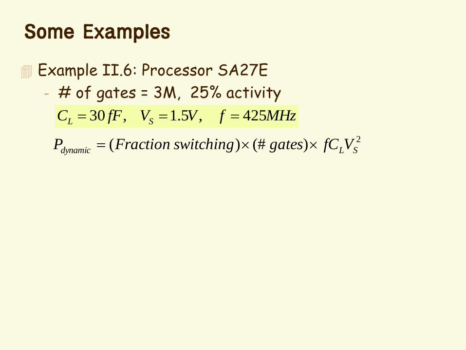
Some Examples
Example II.6: Processor SA27E
- # of gates = 3M, 25% activity
MHzfVVfFC SL 425,5.1,30
2)(#)( SLdynamic VfCgatesswitchingFractionP

Exercise
Estimate the power of the following processor (~ P-IV)
- # of gates = 25M, 25% activity
GHzfVVfFC SL 3,5.1,1
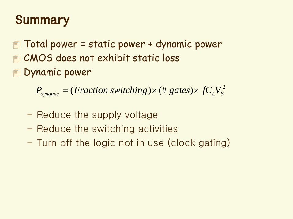
Summary
Total power = static power + dynamic power
CMOS does not exhibit static loss
Dynamic power
– Reduce the supply voltage
– Reduce the switching activities
– Turn off the logic not in use (clock gating)
2)(#)( SLdynamic VfCgatesswitchingFractionP
Chap. 12 Transients in Second-
order Circuits
LC Circuit
RLC Circuits
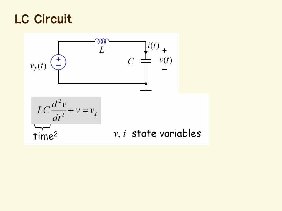
LC Circuit
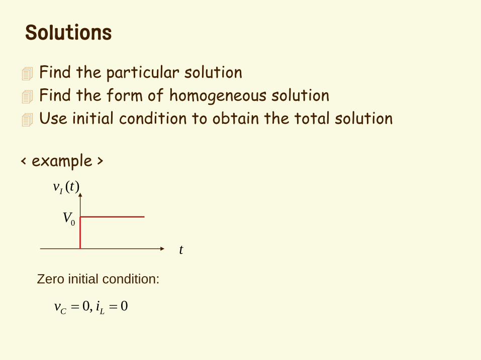
Solutions
Find the particular solution
Find the form of homogeneous solution
Use initial condition to obtain the total solution
< example >
t
0V
)(tvI
Zero initial condition:
0,0 LC iv

Homogeneous Solution
General Form: st
H Aetv )(
LCjsAeeLCAs oo
stst 1,02
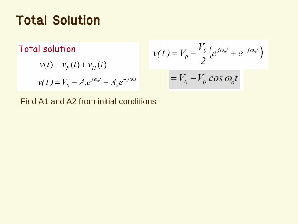
Find A1 and A2 from initial conditions
Total Solution
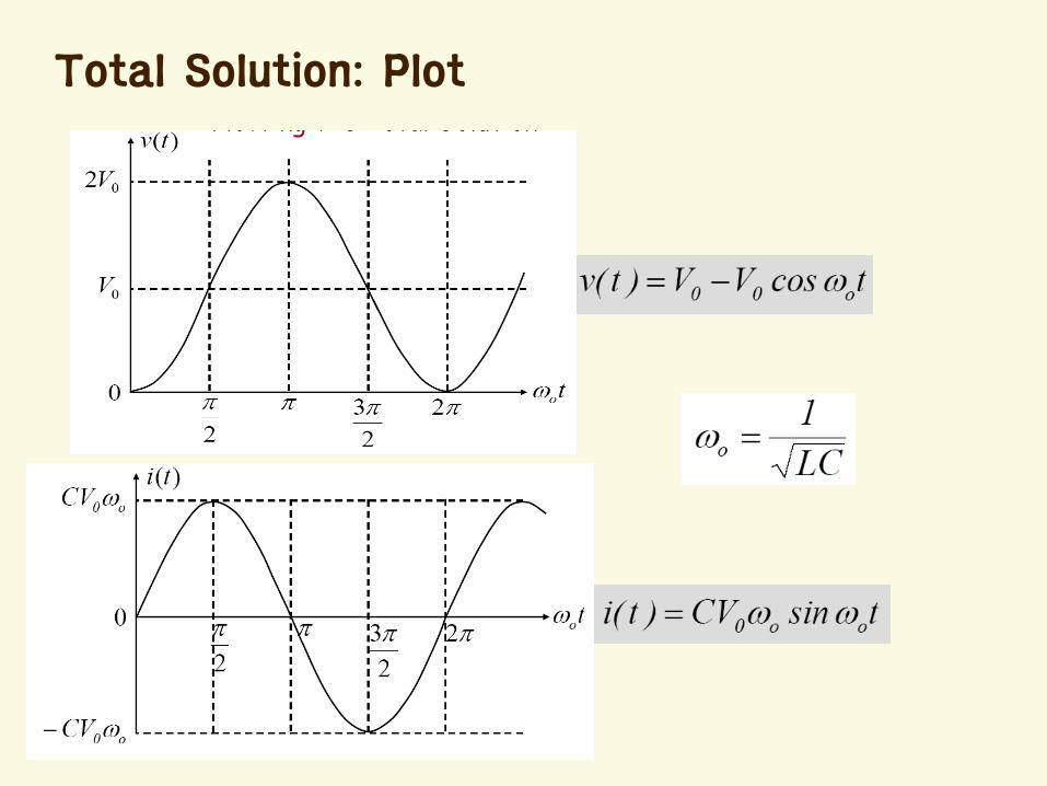
Total Solution: Plot
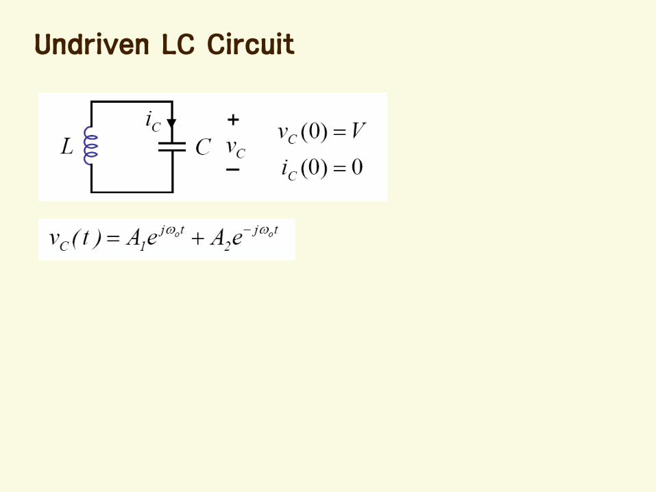
Undriven LC Circuit
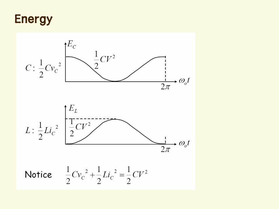
Energy
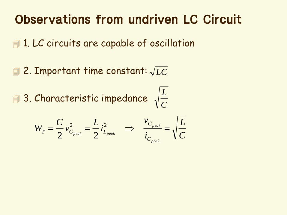
Observations from undriven LC Circuit
1. LC circuits are capable of oscillation
2. Important time constant:
3. Characteristic impedance
LC
C
L
C
L
i
vi
Lv
CW
peak
peak
peakpeak
C
C
LCT 22
22
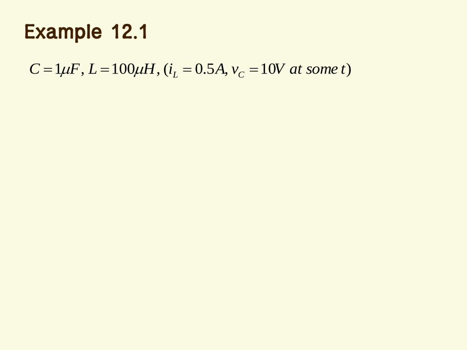
Example 12.1
)10,5.0(,100,1 tsomeatVvAiHLFC CL
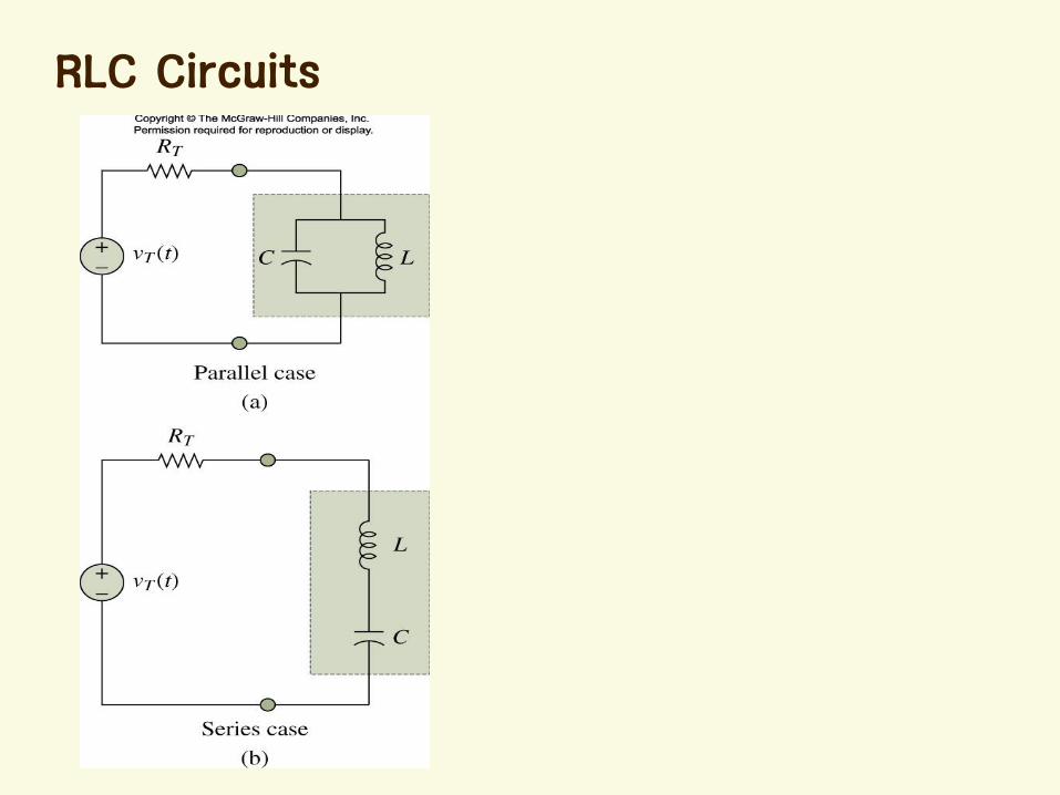
RLC Circuits
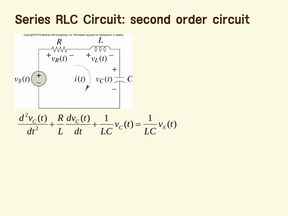
Series RLC Circuit: second order circuit
)(1
)(1)()(
2
2
tvLC
tvLCdt
tdv
L
R
dt
tvdSC
CC
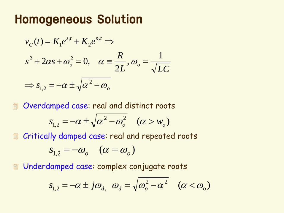
Homogeneous Solution
o
oo
tsts
C
s
LCL
Rss
eKeKtv
2
2,1
22
21
1,
2,02
)( 21
Overdamped case: real and distinct roots
Critically damped case: real and repeated roots
Underdamped case: complex conjugate roots
)(22
2,1 oo ws
)(2,1 oos
)(22
,2,1 ooddjs
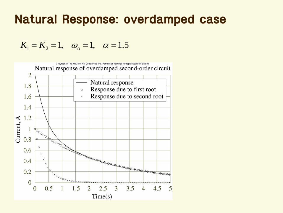
Natural Response: overdamped case
5.1,1,121 oKK
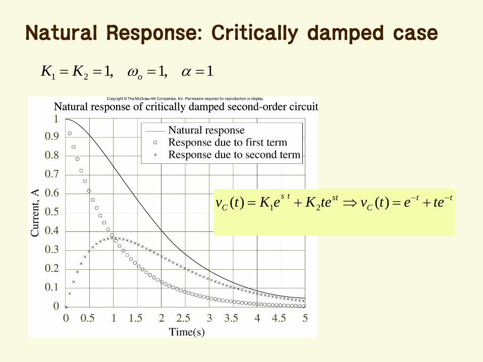
Natural Response: Critically damped case
1,1,121 oKK
tt
C
stts
C teetvteKeKtv )()( 21
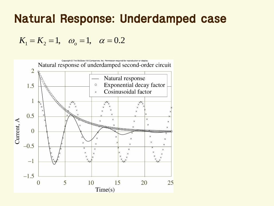
Natural Response: Underdamped case
2.0,1,121 oKK
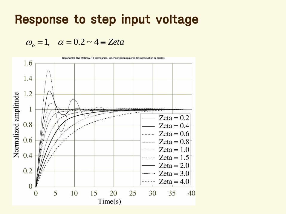
Response to step input voltage
Zetao 4~2.0,1
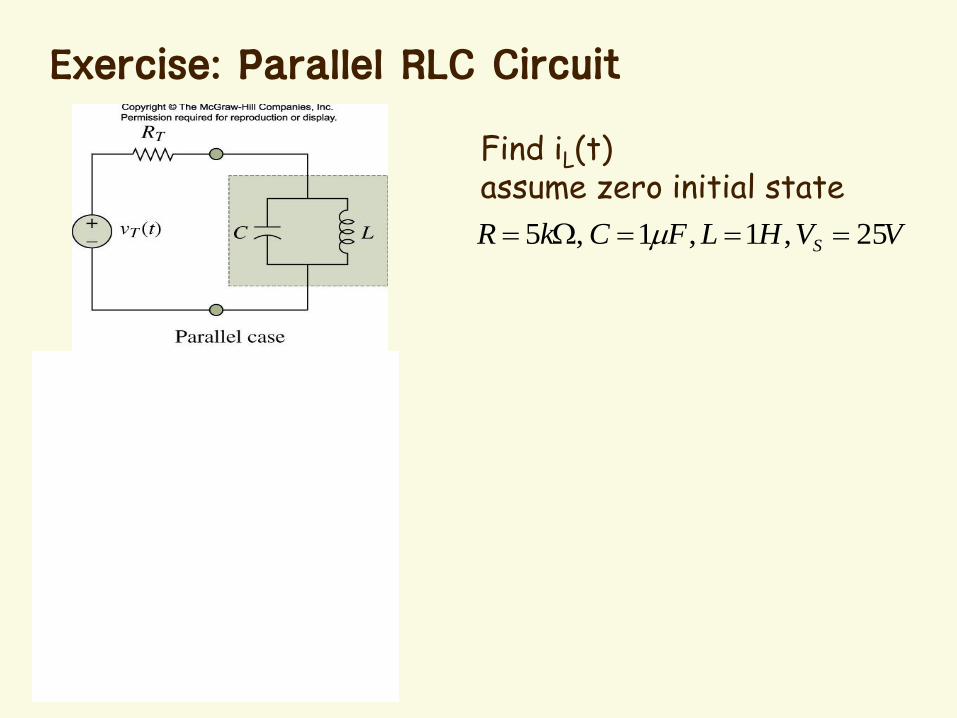
Exercise: Parallel RLC Circuit
VVHLFCkR S 25,1,1,5
Find iL(t)assume zero initial state
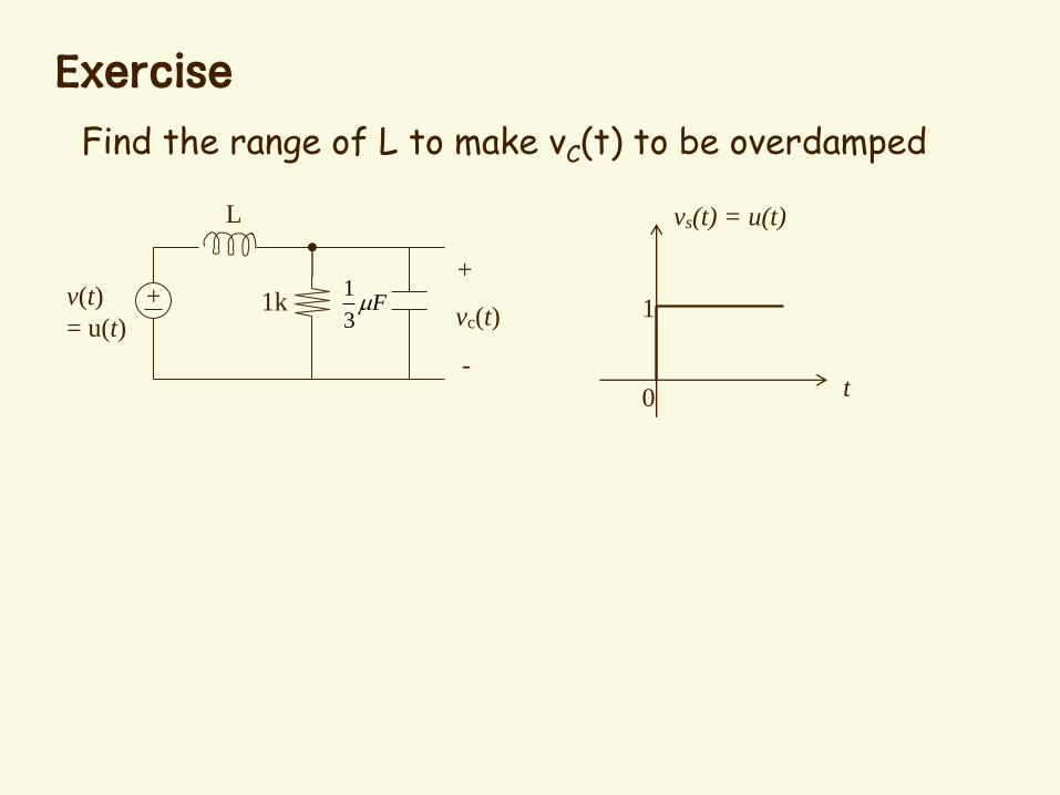
Exercise
+
L
1kv(t)
= u(t)
+
-
vc(t)F
3
1
Find the range of L to make vC(t) to be overdamped
1
0 t
vs(t) = u(t)

Find the differential equation for capacitor voltage. Find the total response with the following initial condition. iL (0) = 4 mA, vC (0) = 0 (V)
2k
F
1H
1
4
2k
4mA
+
-
vc(t)
+-
12V
Exercise
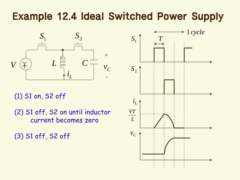
Example 12.4 Ideal Switched Power Supply
+
-
CCv
Li
1S 2S
LV
1S
2S
Tcycle1
Li
Cv
(1) S1 on, S2 off
L
VT(2) S1 off, S2 on until inductorcurrent becomes zero
(3) S1 off, S2 off
Summary
LC Circuit
RLC Circuit
– Three kinds of transient responses• Over-damped
• Critically damped
• Under-damped
Chap. 13 Sinusoidal Steady State:
Imdepance and Frequency
Response
Sinusoidal Steady-state Response
Impedance
Frequency Response
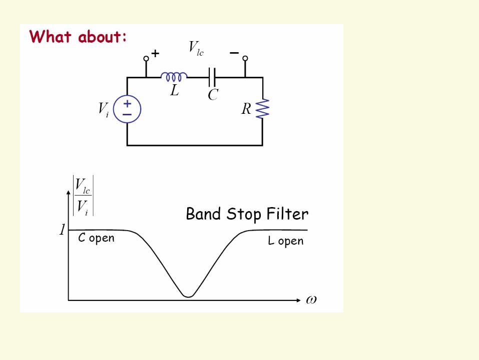
Filter
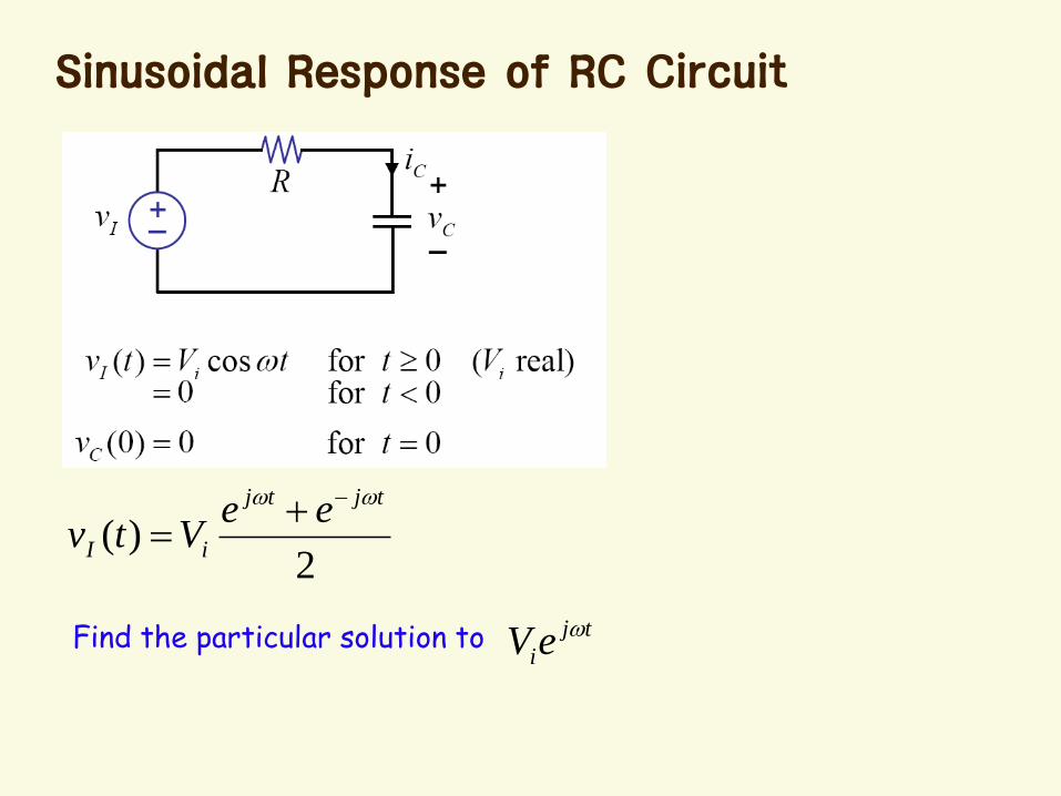
Sinusoidal Response of RC Circuit
2)(
tjtj
iI
eeVtv
Find the particular solution to tj
ieV

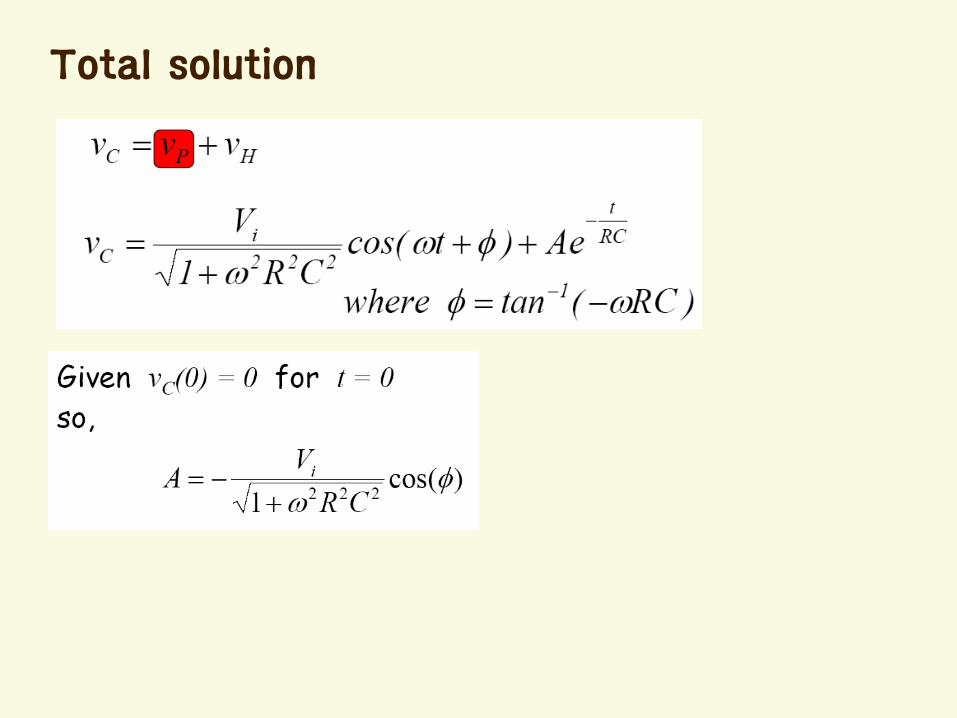
Total solution
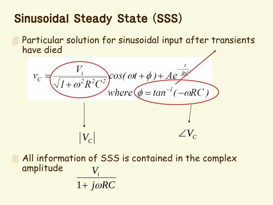
Sinusoidal Steady State (SSS)
Particular solution for sinusoidal input after transients have died
All information of SSS is contained in the complex amplitude
CV CV
RCj
Vi
1

Magnitude Plot
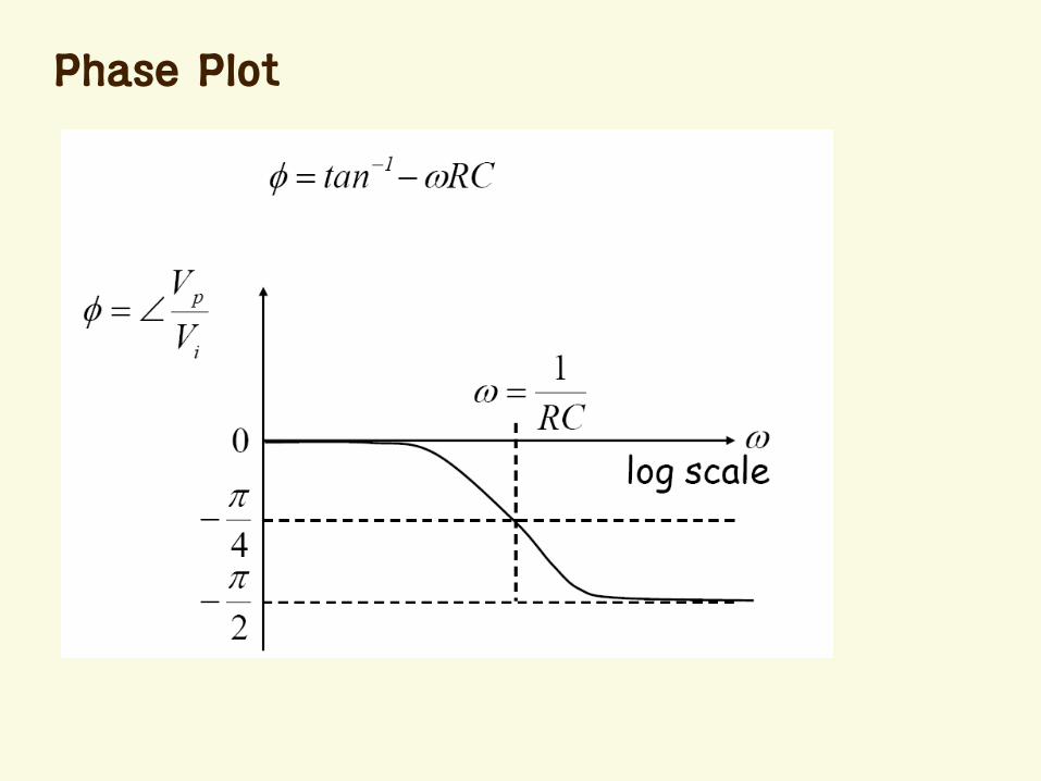
Phase Plot
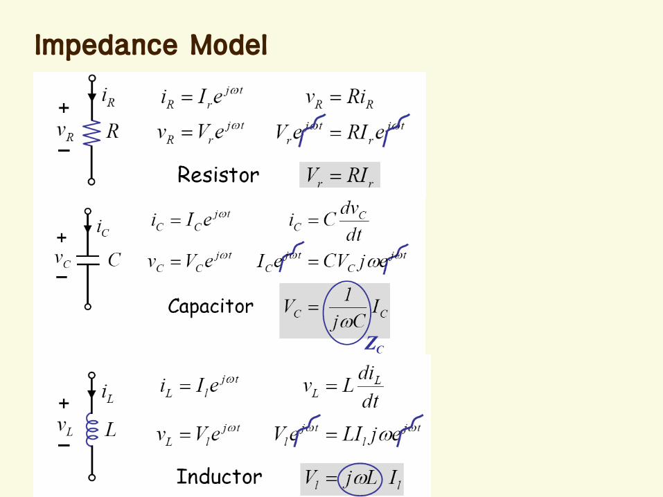
Impedance Model
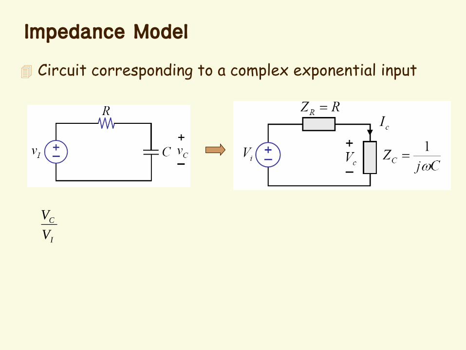
Impedance Model
Circuit corresponding to a complex exponential input
I
C
V
V
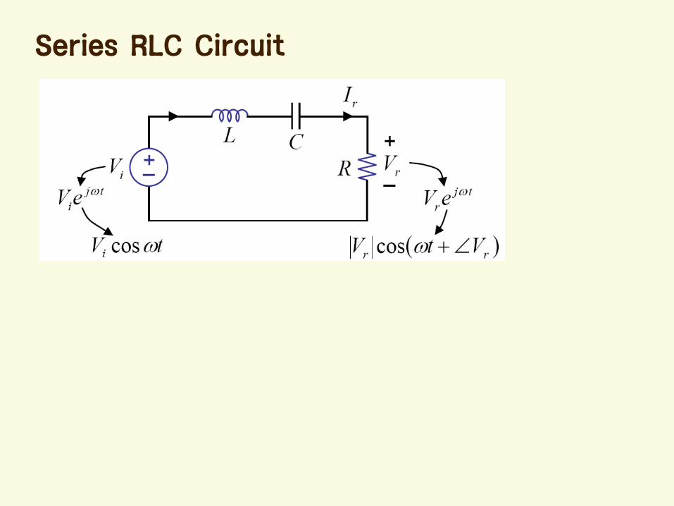
Series RLC Circuit
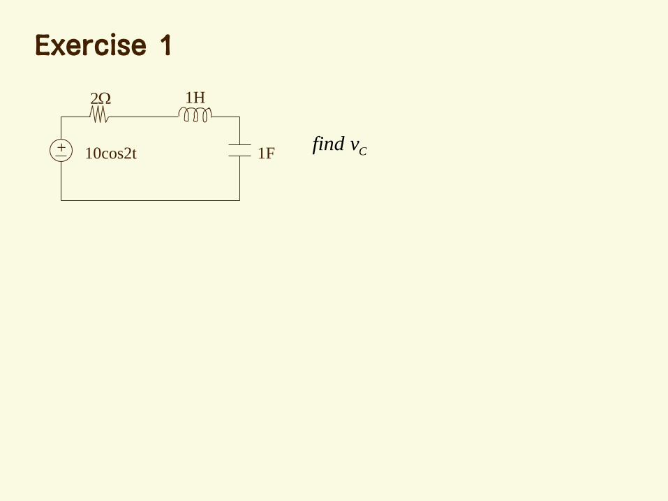
Exercise 1
+
1H2
1F10cos2t Cvfind

Find v(t) at steady state (time unit: msec)
+
1k 2k
+
-
v(t) 1Fsint cos2t
Exercise 2
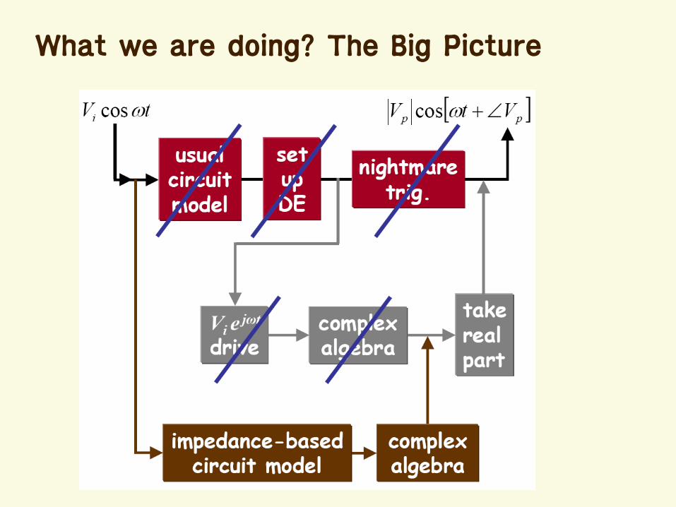
What we are doing? The Big Picture
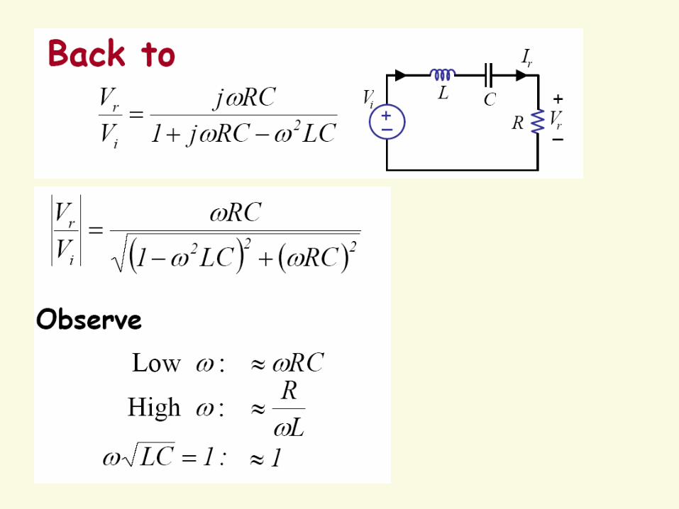
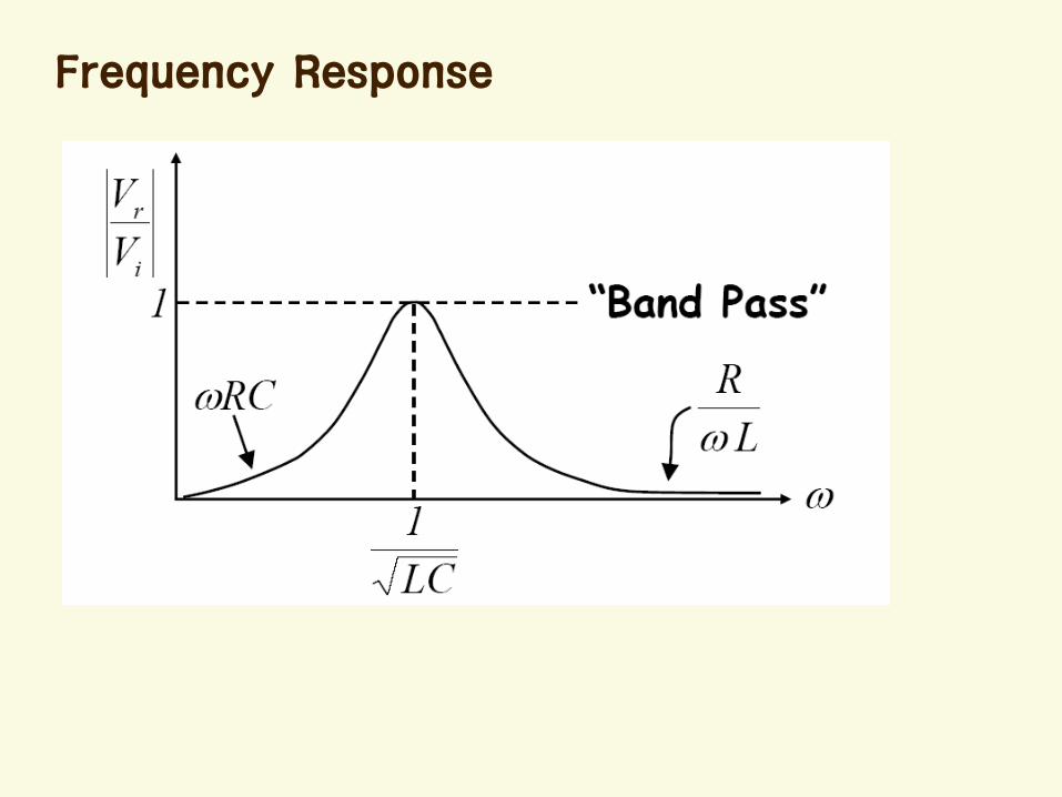
Frequency Response
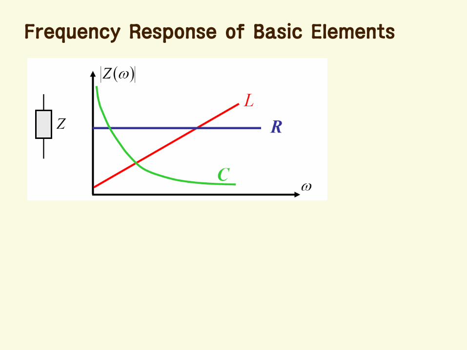
Frequency Response of Basic Elements
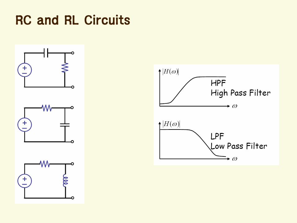
RC and RL Circuits
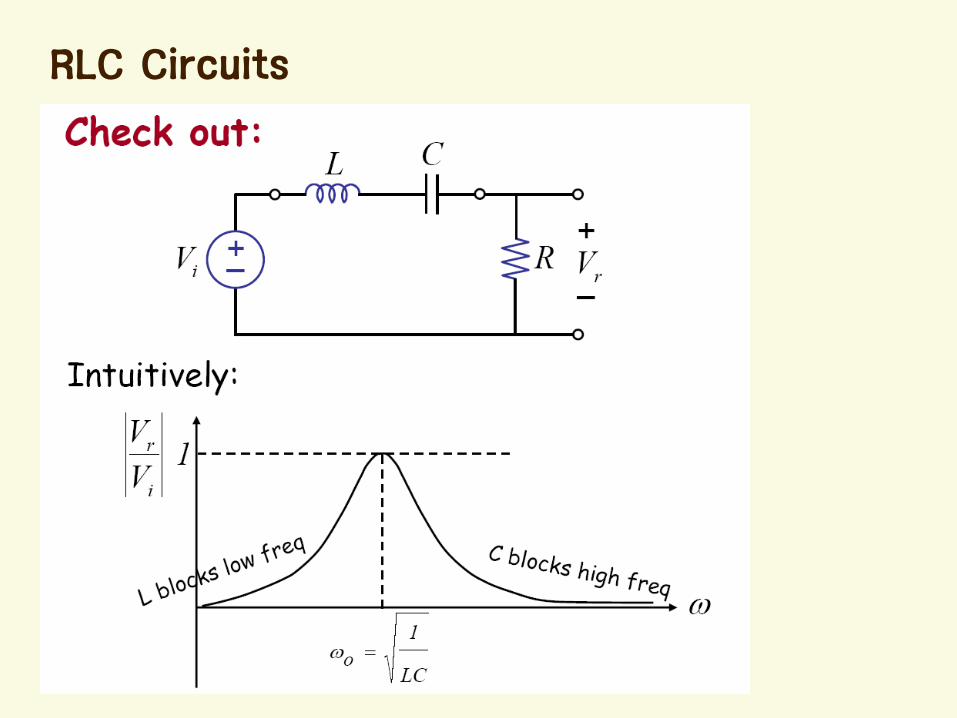
RLC Circuits
Resonance
Equivalent impedance = Resistor
Circuit response is maximum
0 CL ZZ
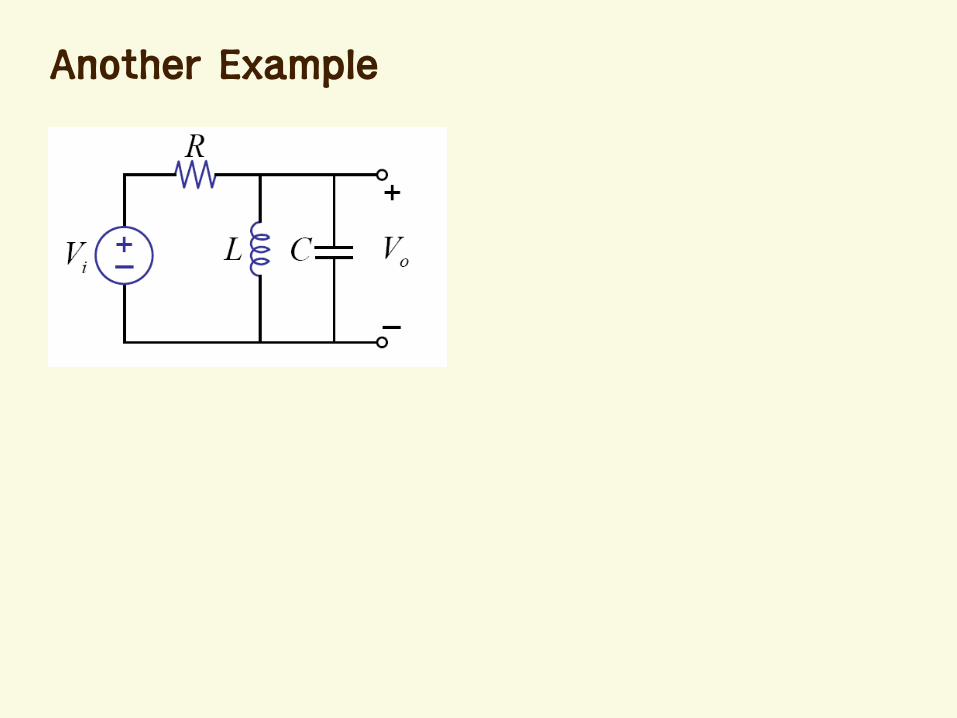
Another Example
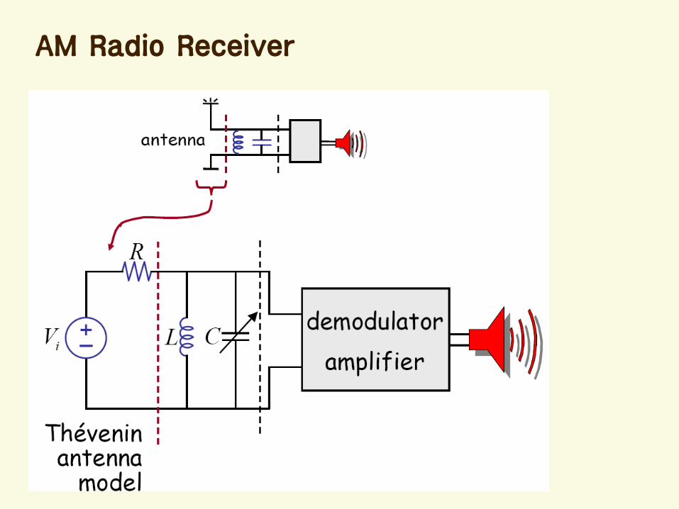
AM Radio Receiver
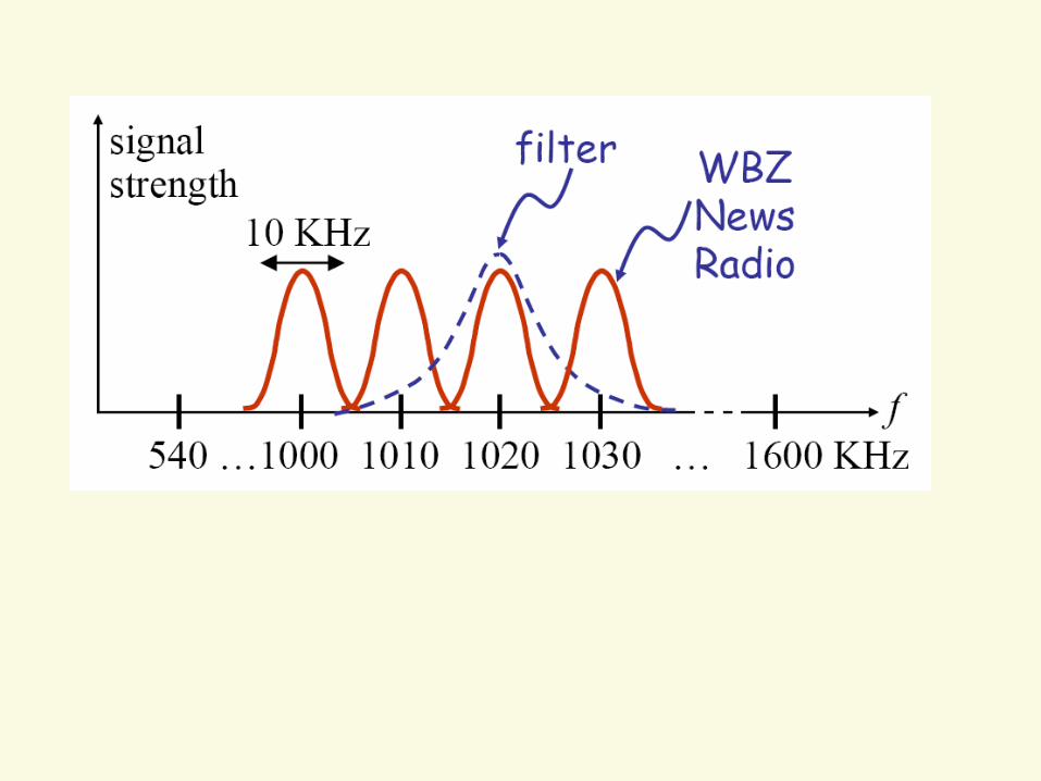
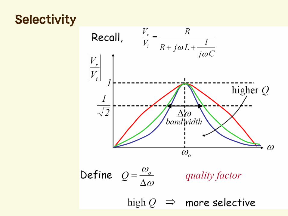
Selectivity
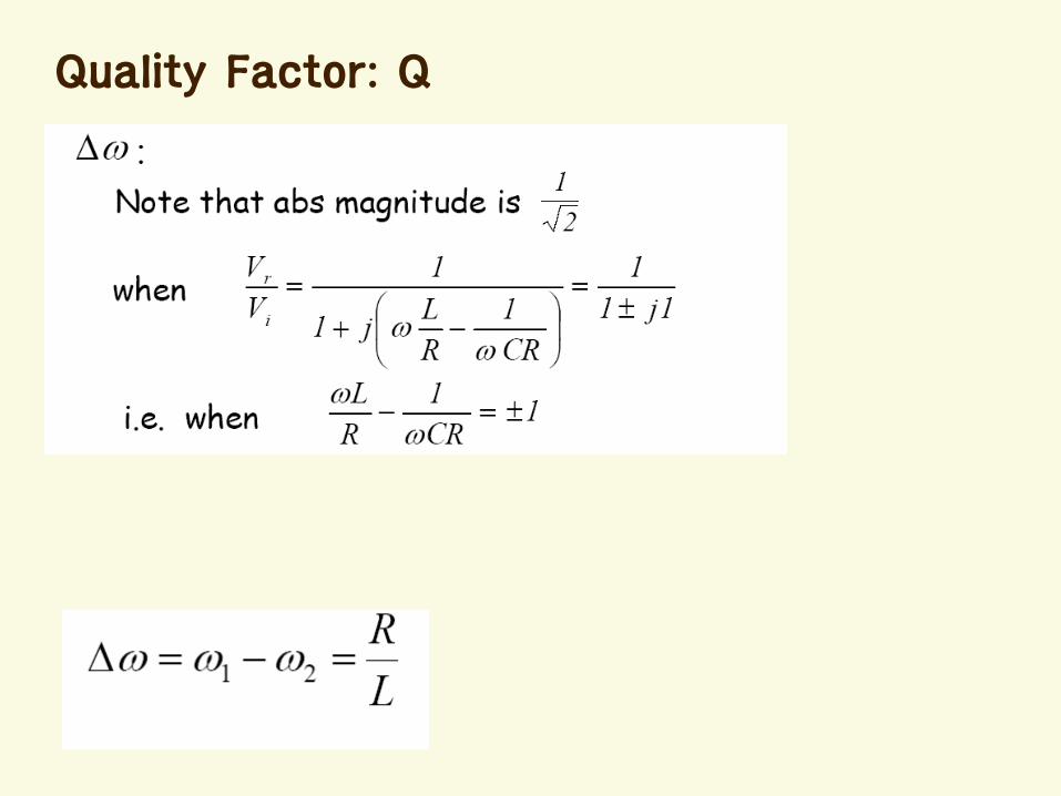
Quality Factor: Q
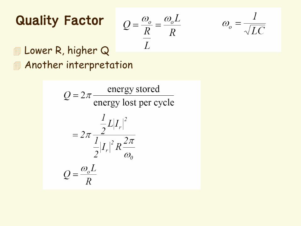
Quality Factor
Lower R, higher Q
Another interpretation
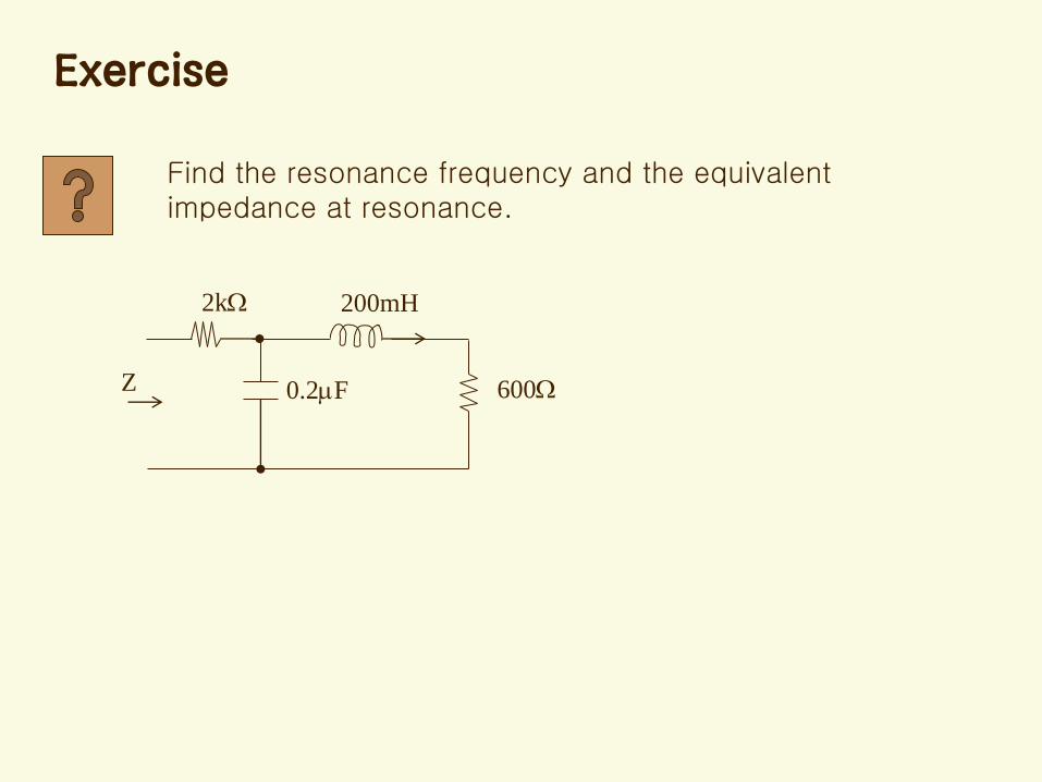
Find the resonance frequency and the equivalent impedance at resonance.
2k
0.2F 600
200mH
Z
Exercise
Summary
Sinusoidal Steady-state Response
Impedance
Frequency Response
Filter


![[OCW] Optimal Design of Energy Systems Chap 15](https://img.pdfslide.net/doc/110x75/623f1ba7ae353868d959820e/ocw-optimal-design-of-energy-systems-chap-15.jpg)