Embed Size (px)
Citation preview

Chapter 1 EE 620, IIT Bombay 1
Introduction to Semiconductors
• Electronic properties of solid state materials• Semiconductors in equilibrium: band diagram and
statistics• Semiconductors under perturbation: carrier transport,
generation, and recombination
(Many concepts have been covered in 207 and 733, and therefore this chapter will go through quickly).
Chapter 1

Chapter 1 EE 620, IIT Bombay 2
• Bandgap viewpoints on solid state materials (and why Si is “close to” perfect in this perspective)
• Equilibrium carrier statistics (and the fermi level) in intrinsic semiconductors
• Equilibrium carrier statistics (and the fermi level) in extrinsic semiconductors (degenerate and nondegenerate)
(Reading Assignments: Chap 1, Sec. 2.1, Appendix A.3 and A.4 of Taur and Ning)
Three Most Important Topics (MIT) Today

Chapter 1 EE 620, IIT Bombay 3
• Semiconductor is the class of material where the conductivity of the material can be controlled to vary a large orders of magnitude.– Elemental semiconductor: Si, Ge– Compound semiconductor (fixed composition): SiC, GaAs, GaN
– Alloy: Si1-xGex, Al1-xGaxAs, Hg1-xCdxTe, etc.
• Purity: VLSI devices are made of semiconductors with ultra purity: unintentional doping < 10-9 in composition, i.e., 0.001 ppm in solids (how to maintain the periodical potential, instead of governing by traps).– To increase range of control in conductivity – To increase mobility (faster and more powerful devices)
Introduction to Semiconductors
Chapter 1 EE 620, IIT Bombay 4
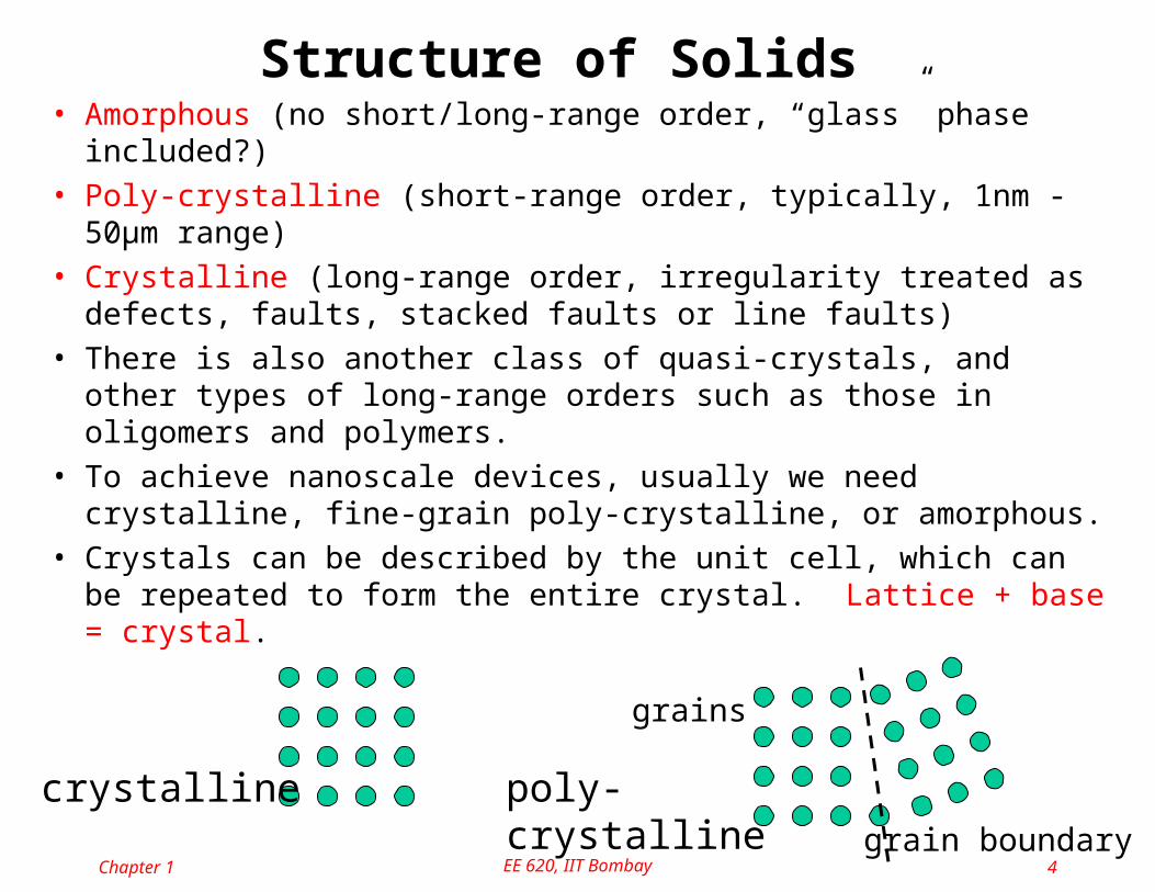
• Amorphous (no short/long-range order, “glass” phase included?)• Poly-crystalline (short-range order, typically, 1nm - 50μm range)• Crystalline (long-range order, irregularity treated as defects, faults,
stacked faults or line faults)• There is also another class of quasi-crystals, and other types of
long-range orders such as those in oligomers and polymers.• To achieve nanoscale devices, usually we need crystalline, fine-
grain poly-crystalline, or amorphous.• Crystals can be described by the unit cell, which can be repeated to
form the entire crystal. Lattice + base = crystal.
crystalline poly-crystalline
grains
grain boundary
Structure of Solids

Chapter 1 EE 620, IIT Bombay 5
Amorphous Polycrystalline Crystal
Grain/domainGrain boundary
Diamond lattice cell(C, Si, Ge, etc.)
Zincblende lattice cell(GaAs, AlAs, GaP, ZnS, etc.)
Atomic Structures

Chapter 1 EE 620, IIT Bombay 6
Crystal Orientation of Cubic Materials• Planes are represented by the
normal vector
• Face-center-cubic (FCC) has 8 corner and 6 face atoms in the Cartesian lattice
• Diamond (covalent, Si, Ge, C, etc.) and Zinc-blend (ionic, GaAs, InP, etc.) consist of 2 interleaved FCC with 1/4 diagonal offset
• Tetrahedral bonding sp3
corner atom in FCCface atom in FCC
(110) (111)
offset by d/4

Zinc Blende
Chapter 1 EE 620, IIT Bombay 7
Can you see the interpenetrating FCC ?
Simple cubic body center cubic face center cubic

Chapter 1 EE 620, IIT Bombay 8
Use of Crystal Orientation• Electrical anisotropy: (100) has
the highest mobility, also scattering rates are slightly different
• Mechanical anisotropy: different surface has different modulus components (later)
• Chemical anisotropy: e.x., KOH will not etch (111)
• Angles: (100) vs. (110): 45, 90 ; (100) vs. (111): 54.74; (110) vs. (111): 35.26, 90 or 144.74
• Important for strain engineering
Newer wafers (8” and 12”) now use a groove to mark the orientation, instead of a cut to save some area for test structures

Chapter 1 EE 620, IIT Bombay 9
• Equilibrium implies detailed balance: carriers relaxed to steady state for both spatial, momentum and energy states
• Frame of reference before perturbation (driving forces)
• Not QM-exact description, but to build a model usable for rapid device analysis. More QM in EE 723. Also, since much material has been gone through in 207 and 733, I will emphasize more on the physical concepts.
• Atom can be approximated with “the core” and “the valence electrons” (similar to the “pseudo-potential” approximation: The core is the filled states of all electrons with the same major quantum number (not so true for the d orbit), such as 1S2, 2S2, 2P6, etc...
Semiconductor Carriers in Equilibrium

Chapter 1 EE 620, IIT Bombay 10
• Valence electrons are:– outermost electrons in orbital concepts
– easiest to break off from the nucleus
– participate in the chemical reactions
– can break the Coulombic potential (ionization) and contribute to conduction
– dominant in chemical and semiconductor discussions (why the periodic table is very important)
• Two descriptions of crystal lattice: the bond (spatial) model and the band (energy) model
Orbit Model: Connection to Chemistry

Chapter 1 EE 620, IIT Bombay 11
• The bond model– simplification from the 3D lattice (usually plotted in 2D)
– every core has nearest neighbors described by chemical covalent bond. Remember that electrons are indistinguishable.
– Electrons breaking free from localization (but still remain in solid) need energy smaller than, but comparable to, the covalence bond strength, due to lattice readjustment and harmonic/aharmonic vibration:
• point defect (substitutional vacancy, atomically compressive stress)
• interstitial Si (interstitials, atomically tensile stress)
• bond breaking and electrons shared.
E
X = bond strain
Lattice spacing at 0K
The Bond and Band Models
Point-defectin the bond model
Ionizationin the bond model

Chapter 1 EE 620, IIT Bombay 12
• In compressive stress: Egap
• In tensile stress: Egap
• T increases: Egap for Si around 300K:
• A totally filled (or totally empty) band cannot contribute to electrical conduction (momentum will cancel for filled bands)
• If somehow a valence electron absorbs Egap energy and enters into the conduction band, it can contribute to conduction
Relations between atomic spacing and energy gap
KeVdT
dEgap /107.2 4
Atomic Spacing and BandgapThe band model: (describe the energy of carriers)
•remember that the carriers are usually indistinguishable•when atoms are brought to close proximity, the energy associated with valence electrons change significantly

Bands
Free electron model is close to Nearly Free Electron Model except at brillouin zones
Chapter 1 EE 620, IIT Bombay 13

Chapter 1 EE 620, IIT Bombay 14
• Insulator (in room temperature) : Egap > 4eV (SiO2: 9.1eV, Si3N4: ~5eV)
• Conductor: Egap < 3 kT ~ 0.1eV, or even negative bandgap
• Semiconductor: anything in between, depending on what temperature we are talking about.
• Regular semiconductor in room temperature: Si: Egap= 1.12 eV; Ge: Egap= 0.66eV and GaAs: Egap= 1.42 eV: this is the system that can be dealt with most easily.
• For wide-bandgap materials (Egap~ 2-3eV), conduction is usually governed more by the structural imperfection (less different than crytalline insulator)
• For narrow-bandgap materials (Egap~ 0.25eV), conduction is usually governed by DOS of available states and Mott transition.
Material Characterization by Bandgap

Chapter 1 EE 620, IIT Bombay 15
Material Characterization by Bandgap
Metal Semi-metal Semiconductor Insulator
E(k) is replaced by E(x) => adding the potential/Efield info

Chapter 1 EE 620, IIT Bombay 16
• Properties of carriers (electrons and holes) in “regular” semiconductors– Charge: as classical (n, p, ND
+, NA and traps)
– Effective mass: almost as classical. It can be defined differently such as effective mass of DOS, effective mass of conduction, etc.
• Equilibrium Carriers statistics (this concerns the number of carriers, and can be “exponentially” controlled)– Similar to [H+][OH] = constant for H+ + OH H2O
Carriers in Semiconductors
2innp True in equilibrium regardless of doping

Chapter 1 EE 620, IIT Bombay 17
Intrinsic case (electrical properties of “pure” semiconductor)– All conduction caused by thermal breakup of electron-hole pairs
– n=p=ni, 1.41010 cm-3 for Si, 2106 for GaAs, and 21013 for Ge at 300K
– There are about 5 1022 atoms/cm3, and 2 1023 valence electrons
– Because the energy for generating electron-hole pairs is from the thermal energy, ni increases exponentially with temperature.
Intrinsic Semiconductors

Chapter 1 EE 620, IIT Bombay 18
• Use of doping (impurity) to create conduction carriers more easily
– The bond model: EB = q4m*/2(4s0)2 EHm*/m0s20.1eV
– N-type material: n ND, p 0 (in linear scale)
– P-type material: p NA, n 0 (in linear scale)
– There is solid solubility limit depending on temperature. Above the limit, the dopants will form segregates.
N-type EB(eV) P-type EB (eV)
Donors Acceptors
P 0.045 B 0.045
As 0.054 Al 0.067
Sb 0.039 Ga 0.072
In 0.16
Doping in Semiconductors

Chapter 1 EE 620, IIT Bombay 19
N-type Semiconductors
Charge species: n and ND+ and n ND
+ in bulk N-type semiconductors for charge neutrality.

Chapter 1 EE 620, IIT Bombay 20
P-type Semiconductors
Charge species: p and NA and p NA
in bulk N-type semiconductors for charge neutrality.
-

Chapter 1 EE 620, IIT Bombay 21
Thermalization of Dopants– This is because the carrier looks at the ionized impurity
through the sea of other Si atoms and valence band, and the bond strength needs to be corrected with the dielectric constant (polarization effect) and the effective mass (periodic potential)
– The binding energy of carriers to impurity atom is much weaker than the Si valence electron to the Si atom.
– In room temperature, regular semiconductors are extrinsic.
Freeze-out extrinsic intrinsic
ni
n/ND
T

Chapter 1 EE 620, IIT Bombay 22
QM Concepts of Density of States (DOS)(see Appendix 3 for derivation from QM)
• From QM and the Pauli principle, there is one allowed state in a phase space of 3D volume (xpx)(ypy)(zpz)=h3.
• If N(E)dE is the number of carrier states per unit volume with an energy between E and E+dE:
• 2: spin degeneracy; g: equivalent minima (valley) of the band. For Si conduction band: g=6 (called six-fold degeneracy)
• If the drift energy is much less than the thermal energy, i.e., the carrier kinetic energy close to the bottom of the parabolic conduction band:
• Notice that the effective mass here is the inverse of the band curvature, and can have anisotropy.
32)(
h
dpdpdpgdEEN zyx
z
z
y
y
x
xC m
p
m
p
m
pEE
222
222

Chapter 1 EE 620, IIT Bombay 23
• If we normalize p with , then the spherical shell of radius p’ has volume of 4p’2dp’, and dE = 2p’dp’, we can derive DOS in the 3D crystals as (assume mx=my=mz=m*):
• Observation: DOS - how many available states for carriers– if 0, the classical approximation gives NC(E) (infinite
number of states at the band edge).– The analogy with the Wankhede stadium: usually there are a lot of
empty states (seats) available. However, if somehow it gets crowded, the carrier has to pile up the higher-energy states.
– If mn* = mp
* , the pile-up will be symmetrical.
– DOS is zero at the band edge in QM sense.– N(E)dE is the available states from E to E + dE, not the carrier
concentration yet!
32
**
32
** )(2)(
)(2)(
EEmm
ENEEmm
ENvpp
vcnn
c
Density of States (Band Model)
xxx mpp 2/'

Chapter 1 EE 620, IIT Bombay 24
• How many states will be filled in a given carrier system?
– The carrier distribution will be described by the Fermi functions (both electrons and holes are Fermions. In contrast, photons and phonons are Bosons). This describes the number of carriers in a specific energy level.
– Given the Fermi energy EF of the system (EF is a constant in equilibrium), the Fermi distribution function with respect to carrier energy is:
TkEE BFeEf
/)(1
1)( Detailed balance in equilibrium!!
Fermi Distribution (Occupancy of States)

Chapter 1 EE 620, IIT Bombay 25
– if E >> EF , f(E) exp( (EF - E)/kBT ), which is the Boltzmann distribution for electrons
– if E << EF , f(E) 1 - exp(- (EF - E)/kBT ) or holes for exp( -(EF - E)/kBT ),
– if E = EF , f(E) = 0.5
f(E)
EF
f(E)
EF
T=0 T>0
TkEE BFeEf
/)(1
1)(
0.50.5
The Fermi Function
Below EF: occupied Above EF: occupied

Chapter 1 EE 620, IIT Bombay 26
• The electron and hole concentrations (in both intrinsic and extrinsic cases) are defined as:
• For convenience, we will define NC and NV as the effective DOS of the conduction band and the valence band.
v
bot
top
c
E
E v
E
E c dEEfENpdEEfENn ))(1)(()()(
31932
3
0
*19
2
3
2
*
31932
3
0
*19
2
3
2
*
108.11051.22
2
102.31051.22
2
cmcmm
m
π
TkmN
cmcmm
m
π
TkmN
pBpv
nBnc
DOS and the Distribution Function: Carrier Concentration
Define:

Chapter 1 EE 620, IIT Bombay 27
• The fermi function is necessary for degenerate materials or heavy injection/inversion/accumulation.
• Notice that Nc(Ec) = Nv(Ev) = 0 at the band edge and then increase according to the square root.
• f(E) = 0 and f(E -)=1 (states much above EF is empty!)
0
2/1
2/1 1)(
ce
dF c
TkEEifeNTk
EEFNp
TkEEifeNTk
EEFNn
BvFTkEE
vB
Fvv
BFcTkEE
cB
cFc
BFv
BcF
32
32
/2/1
/2/1
The Fermi Integral and Its Approximation

Chapter 1 EE 620, IIT Bombay 28
– For undoped intrinsic materials: n=p=ni since all electrons and holes are generated in pairs. If we assume EF will be deep in the bandgap (later on we will see this assumption is valid except for materials with very narrow bandgap), and the Boltzmann approximation can be used (instead of the Fermi integral). Cancel EF in n=p= ni:
E
n
EcEF
Ev
Nc f(E)
TkEvci
BgapeNNn 2/
Ei
Carrier Concentrations and the Band Diagram
NV

Chapter 1 EE 620, IIT Bombay 29
– Cancel Nc and Nv:
– Cancel ni to obtain EF for intrinsic materials (which we denote as Ei)
E
n
2/)(/)(i
TkEEi
TkEEi nnpenpenn BFiBiF
)ln(4
3
2)ln(
22 *
*
n
pBvc
c
vBvci m
mTkEE
N
NTkEEE
For Si at 300K, 0.3kBT
Intrinsic Levels in the Band Diagram
Ec
Ev
Nc f(E)
EF=Ei
NV

Chapter 1 EE 620, IIT Bombay 30
– For extrinsic materials, we still have total charge neutrality: p - n + ND
+ - NA -
= 0 and constant EF in space:
– For extrinsic materials we further have
iDA
iADA
D
iDAD
npNcheckN
nnNpNNif
N
npNnNNif
4162
2
1010
typepn
NTkEEtypen
n
NTkEE
i
ABFi
i
DBiF
lnln
Fully-ionized Dopant in Nondegnerate Materials

Chapter 1 EE 620, IIT Bombay 31
• Nondegernate conditions (where Boltzmann approx. can be used safely)
• Above this level, we can use some correction factor on ni, and keep the simpler exponential relations.
• Much higher than this level (>51019), especially over the solid soluability, more physical effects such as band tailing (merging of impurity level and conduction band) and Mott transition can happen, when the equations derived above cannot be used anymore. However, EF for heavily-doped n-type can be approximated at EC, for p-type, at EV.
317318 101.9106.1 cmNcmN AD
Degenerately-Doped Semiconductors

Chapter 1 EE 620, IIT Bombay 32
Dopant Ionization
kTEEDD
D
DFegN
N/1
1
kTEEAA
A
FAegN
N/1
1
kTEEkTEETT
T
TFTF eegN
N// '
1
1
1
1
TTT gkTEE ln'
• For shallow dopants (ND and NA) at room temperature before the degenerate conditions: full ionization
• For deep levels (NT), local EF is important to determine ionization
• At low temperature, to keep the ionization in bounds, EFED

Chapter 1 EE 620, IIT Bombay 33
Fermi Level and Dopant Ionization

Chapter 1 EE 620, IIT Bombay 34
Approximation for Degenerate Semiconductors• Within the band diagrams, degenerate doped semiconductors have
EF at EC (N-type) or EV (P-type)
• Complicated physics or behavior can happen, including band tailing, Mott transition and heavy dopant segregation.
• For carrier statistics, we can correct either ni (effective intrinsic concentration) or Egap (apparent bandgap narrowing)
• Bandgap narrowing can be expressed from the Fermi integral, but more often directly from experimental fit.
kTEnkTEENNnnp gapigapgapVCie /exp/exp 22
31717
217
31717
105.010
ln10
ln0.9
107107
ln7.18
cmNNN
meVNE
cmNN
meVNE
AAA
Agap
DD
Dgap

Chapter 1 EE 620, IIT Bombay 35
Properties of Si and SiO2 at room temperature
Physical property Si SiO2
Atomic/molecular density (cm-3) 51022 2.31022
Crystal structure Diamond AmorphousCovalent radius (Å) 1.11 around 1Egap (eV) 1.12 9.1Dielectric constant 11.7 below 3.9Intrinsic density 1.4 1010 -Carrier mobility (cm2/Vs) Electron: 1440 -
Hole: 470 -Effective DOS (cm-3) NC: 3.2 1019 -
NV: 1.8 1019 -Breakdown field (V/cm) 3 105 > 107
Melting point (C) 1410 1600-1700Thermal conductivity (W/cm C) 1.5 0.014

Chapter 1 EE 620, IIT Bombay 36
• The bulk resistance of uniform semiconductors (mobility)
– Bonus MIT: Einstein relation between mobility and diffusivity
• Direct implications from the Poisson equation (Debye length and the potential curvature)
• The continuity equation and the carrier response time (minority and majority)
Reading assignment: 2.1.3; 2.1.4; Appendix 4
of Taur and Ning
Three MITs For Carrier Actions

Chapter 1 EE 620, IIT Bombay 37
Carrier Action under Perturbation• Equilibrium: no current and no information can be represented.
• Perturbation is necessary to artificially encode information in perturbed states: electric field (drift), concentration gradient (diffusion), temperature gradient (thermal diffusion) and excess carriers (R-G), and radiation (photoelectric R-G)
– Drift current: when the carriers in semiconductor is under equilibrium, all random motion in k (phase) space is exactly cancelled: no current flowing and the system has a constant Fermi energy
– However, when there is an electric field F, the forward motion is preferred among all randomizing scattering: a skew in distribution function of k space will result in net current.
– If in steady-state and constant F: F = - = EC/q, (electric field causes band bending)
n(k)
kkx
ky
EF
Fx
Fx

Chapter 1 EE 620, IIT Bombay 38
• Surprizing result from newtonian mechanics’ perspective F=ma
• Jp drift = qp vp = qpp F with vp = p F
• Jn drift = -qn vn = qn n F with vn = -n F
• The mobility is in the unit of cm2/Vs and is the same as the Ohm’s law. Actual picture is: acceleration, scattering…v=aF
• Perfect crystal at T=0 has no scattering
• Scattering sources disturb crystal periodicity• The major scattering events in semiconductors
– phonon scattering (lattice vibration ie T)
– impurity scattering (ionized and neutral impurity => no temp dependence)
– surface scattering (termination of periodic potential)
Drift Velocity and Carrier Mobility
pn qpqn
1
T
impurity
phonon
total
T
Dopant freeze-out
Mobility reduction
...1111
surfaceimpurityphonontotal Matthiessen’s rule:

Scattering• Impurity- random potential well or barrier in band
structure will cause scattering
• Phonons: At various electronic kinetic energies, various phonon modes can be excited – Optical phonons start participating at higher energies
– Acoustic phonons participate at lower energies
Chapter 1 EE 620, IIT Bombay 39
E
k
Optical phonons
Acoustic phonons
Electron E-k vs x
Evs x

Chapter 1 EE 620, IIT Bombay 40
• Velocity Saturation: phenomenological expressions, since the physical effects behind the velocity saturation is too complex to give good physical functions directly optical phonon scattering is stronger when the carrier has larger
kinetic energy. Many popular semiconductors have velocity saturation around 107
cm/s (1/1,000 of speed of light) n = 0/ (1 + (0F/vsat))1/, where vsat is the saturation velocity
conduction mobility is derived from the effective mass of conduction and the mean free time of collision.
For Si, n = 1360 cm2/Vs and p=460 cm2/Vs at room temperature for intrinsic samples
F F
vdrift
vsatn
High-field Mobility: Velocity Saturation

Chapter 1 EE 620, IIT Bombay 41
• Four-point probe: since in most thin-film technology only the surface is accessible, the resistivity is often expressed as / �: every square on the uniformly-doped wafer surface, regardless of its size, has the same resistivity (length cancelled with width). Also, it is usually combined with the hot-point probe, with the current source replaced by the thermal current generation to distinguish the type.
• Eddy-current: induce Eddy current and measure power consumption at the RF/microwave source. This is a non-contact method and can be used as in-situ measurement of sample resistivity.
V
Measurement of mobility or resistivity
Chapter 1 EE 620, IIT Bombay 42
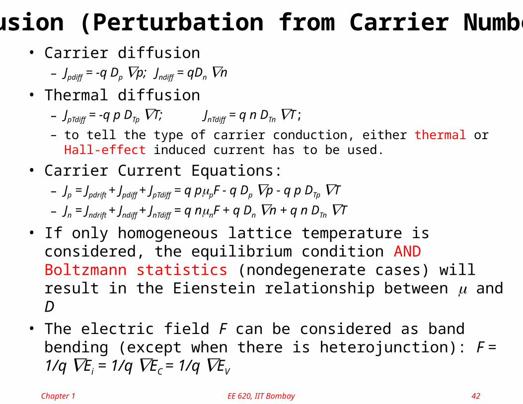
• Carrier diffusion– Jpdiff = -q Dp p; Jndiff = qDn n
• Thermal diffusion– JpTdiff = -q p DTp T; JnTdiff = q n DTn T;
– to tell the type of carrier conduction, either thermal or Hall-effect induced current has to be used.
• Carrier Current Equations:– Jp = Jpdrift + Jpdiff + JpTdiff = q ppF - q Dp p - q p DTp T
– Jn = Jndrift + Jndiff + JnTdiff = q nnF + q Dn n + q n DTn T
• If only homogeneous lattice temperature is considered, the equilibrium condition AND Boltzmann statistics (nondegenerate cases) will result in the Eienstein relationship between and D
• The electric field F can be considered as band bending (except when there is heterojunction): F = 1/q Ei = 1/q EC = 1/q EV
Diffusion (Perturbation from Carrier Numbers)

Chapter 1 EE 620, IIT Bombay 43
Einstein Relation• For homogeneous T, equilibrium 1-D, non-degenerate doping
• In equilibrium dEF/dx = 0
• Out of equilibrium dEF/dx 0
– This last expression can also be derived from assumed distribution function, and is an important relation to remember: Jn EFn
• Please compare with another point of view in Appendix 4
charge)(space01
0 dx
dE
qF
dx
dnqDnFqJ i
nnN
FD
nnF
Tk
q
dx
dE
dx
dEen
Tkdx
dnenn
n
n
B
FiTkEEi
B
TkEEi
BiFBiF
/)(/)( 1
q
TkDD B
p
p
n
n
00 FnnnFn
FpFn EqnJdx
dEEE

Chapter 1 EE 620, IIT Bombay 44
Electron-Hole Pair Generation-Recombination• Fick’s law for carrier conservation (or the continuity equation):
• Remember that traps are localized allowable states within the bandgap for electrons and/or holes. Since trap states are local in space, they cannot cause drift current directly, but their charge states will affect the Poisson equation and continuity equations
• The generation-recombination events in semiconductors can be categorized by band-to-band, band-to-trap and trap-to-trap. The required conservation of total momentum and energy will be completed by interaction with phonons (thermal), photons (light) or another carrier (impact ionization and Auger recombination)
ppp
nnn
RGJqt
p
RGJqt
n
1
1

Chapter 1 EE 620, IIT Bombay 45
thermal optical carrier
band-to-band
band-to-trap
trap-to-trap
Generation-Recombination
(elec. capture) (elec. capture)
(impact ionization)
(change in energy)
(change in location)(trap hopping/tunneling)
Category of Generation-Recombination
• Photons have large energy but small momentum, not effective for indirect bandgap
• Phonons have small energy (kT/q) but large momentum, not effective for 1.1eV bandgap
• Trap assisted generation-recombination is most efficient at mid-gap (Au, Cu, Mn, Cr, Fe in Si)

Chapter 1 EE 620, IIT Bombay 46
• Two thermal band-to-trap processes that complete a band-to-band electron-hole pair generation or recombination are called SRH (Shockley-Read-Hall) processes, which is most important in Si.
• Recombination is proportional to the number of carriers (p), number of traps (NT) and capture coefficient (cp), which has the unit of a cross section (cm2) the recombination velocity (cm/s).
• In equilibrium, generation has to cancel recombination (detailed balance). Off equilibrium, the net generation-recombination is then:
• A more general expression preserving the low-injection limit:
0pNct
ppNc
t
pTp
GTp
R
nGRpTpTp
GR
n
t
nppNcppNc
t
p
)( 0
kTEEi
kTEEi
pn
i
GRGR
TiiT enpennppnn
npn
t
n
t
p /)(1
/)(1
11
2
)()(
Shockley-Read-Hall (SRH) processes
GR always pushes towards equilibrium

Chapter 1 EE 620, IIT Bombay 47
• Semiconductor carriers interact with photons first through generation/recombination, and when the photon energy is higher (X-ray), plasmons (collective motion of atoms) will participate in. Optical generation of electron-hole pairs is the basic principle for optical sensors and solar cell, while optical recombination is the basic principle for LED and laser diodes.
• Absorption of light in semiconductors increases when the photon energy increases (the wave length decreases). When the photon energy is less than the bandgap, phonon interaction is required for the low-level absorption
xphoton
xphoton
opop eIIeGG 00
op
Optical Generation and Recombination

Chapter 1 EE 620, IIT Bombay 48
• A three-particle interaction with both energy and momentum conservation
• The phenomenon is quite complex since the nonlinearity in band diagram and capture cross section
• Phenomenologically, the term can be expressed as multiplication-like ideas:
where n0 is the impact ionization coefficient, n and p are the Auger capture coefficient which is usually important only in very high injection areas (lasers/power devices)
2
0
0
ipnaun
F
F
nnn
niin
nnppnR
eq
JG
nn
Impact ionization and Auger recombination
Chapter 1 EE 620, IIT Bombay 49
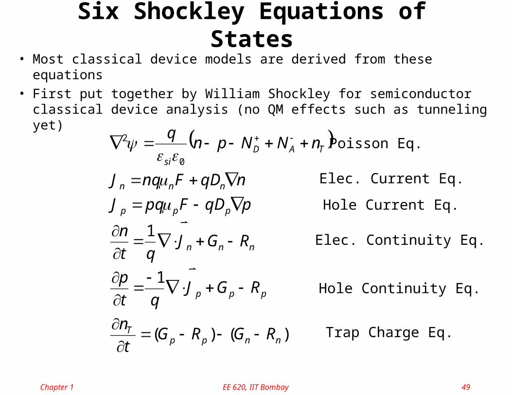
Six Shockley Equations of States
• Most classical device models are derived from these equations
• First put together by William Shockley for semiconductor classical device analysis (no QM effects such as tunneling yet)
)()(
1
1
0
2
nnppT
ppp
nnn
ppp
nnn
TADsi
RGRGt
n
RGJqt
p
RGJqt
n
pqDFpqJ
nqDFnqJ
nNNpnq
Poisson Eq.
Elec. Current Eq.
Hole Current Eq.
Elec. Continuity Eq.
Hole Continuity Eq.
Trap Charge Eq.

Chapter 1 EE 620, IIT Bombay 50
Screening and Debye Length
• The net charge, normalized by the dielectric constant (or called permittivity), is the curvature of the potential and the slope of F.
• In the 1-D system considering only one type of carriers, if (x) is perturbed by ND+dND(r), the equation becomes:
cmF
x
dx
dF
dx
d
rdielectric
dielectric
/1085.87.11
)(
140
2
2
Poisson Eqn in 1-D,
D
BsiD
D
DsiBsi
D
Nq
TkL
L
x
Nq
Tk
Nq
dx
d
20
00
2
2
2
exp
• LD is the Debye length. It takes LD to resolve the potential perturbation from the change in net charge. For example, LD =0.04m for ND =1016cm-3 in Si.
for Si

Chapter 1 EE 620, IIT Bombay 51
Diffusion Length and Dielectric Relaxation Time
• If Jn is negligible (carrier injection), the minority carrier decays in the order of n (minority carrier lifetime ~ms-s).
• In steady state (no time variation) and the drift current is small for minority carriers n exp(-x/L) with L=(Dnn)1/2 being the diffusion length (usually on the order of 10-100m in Si).
x
nqDFqnJ
nn
x
J
qt
nnnn
n
n
)(1 0
In 1-D p-type materials, the minority carriers (n0ni2/NA)
• n(t) exp(-t/nsi0), where nsi0 is called the dielectric relaxation time (observe the similarity to RC time constants), or the majority-carrier response time, and is typically < 10-12s.
0
1
sinnn
n qn
x
FF
x
nqDFqnJ
x
J
qt
n
In 1-D n-type materials, the majority carriers in the “Ohmic region”