Embed Size (px)
Citation preview
05/02/1437
1
Chapter 1 Introduction
1-3 ENGINE CLASSIFICATIONS
Internal combustion engines can
be classified in a number of
different ways:
1. Types of Ignition
05/02/1437
2
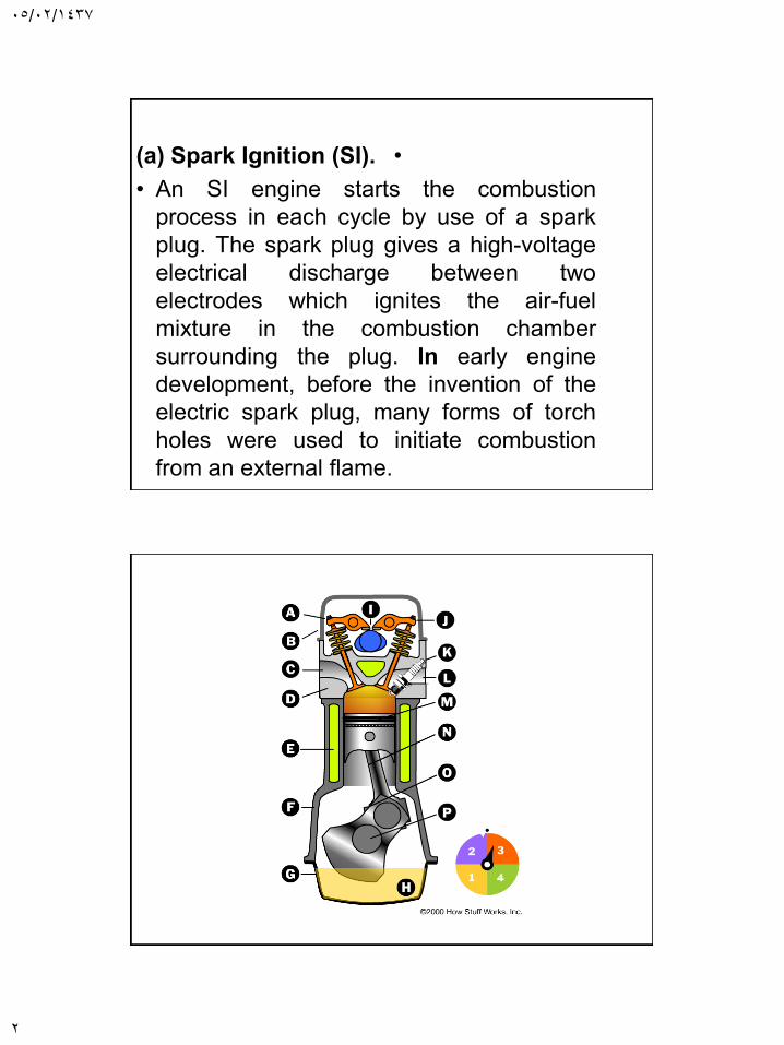
•(a) Spark Ignition (SI).
• An SI engine starts the combustion
process in each cycle by use of a spark
plug. The spark plug gives a high-voltage
electrical discharge between two
electrodes which ignites the air-fuel
mixture in the combustion chamber
surrounding the plug. In early engine
development, before the invention of the
electric spark plug, many forms of torch
holes were used to initiate combustion
from an external flame.
05/02/1437
3
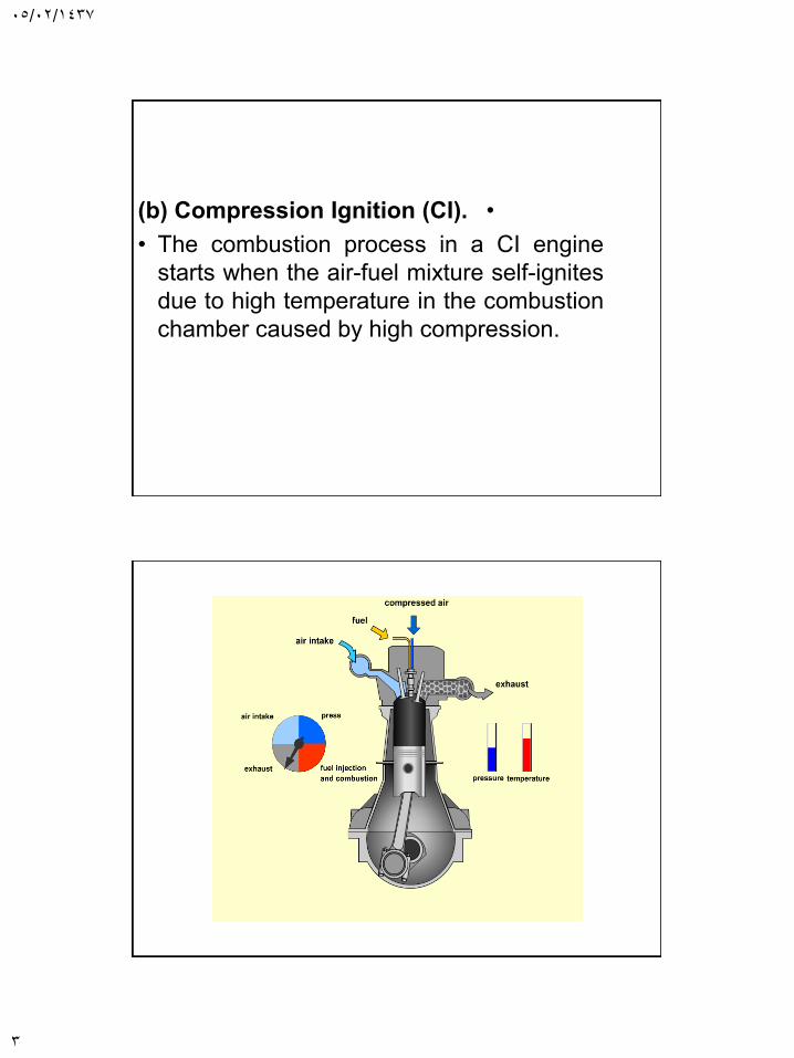
•(b) Compression Ignition (CI).
• The combustion process in a CI engine
starts when the air-fuel mixture self-ignites
due to high temperature in the combustion
chamber caused by high compression.
05/02/1437
4
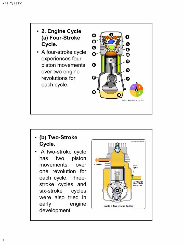
• 2. Engine Cycle
(a) Four-Stroke
Cycle.
• A four-stroke cycle
experiences four
piston movements
over two engine
revolutions for
each cycle.
• (b) Two-Stroke
Cycle.
• A two-stroke cycle
has two piston
movements over
one revolution for
each cycle. Three-
stroke cycles and
six-stroke cycles
were also tried in
early engine
development
05/02/1437
5
3. Valve Location (see Fig. 1-4)
(a) Valves in head (overhead valve), also called I
Head engine.
(b) Valves in block (flat head), also called L Head
engine. Some historic
engines with valves in block had the intake valve on
one side of the cylinder
and the exhaust valve on the other side. These were
called T Head engines.
(c) One valve in head (usually intake) and one in
block, also called F Head engine; this is much less
common.
4. Basic Design
(a) Reciprocating. Engine has one or more
cylinders in which pistons reciprocate back and
forth. The combustion chamber is located in the
closed end of each cylinder. Power is delivered to a
rotating output crankshaft by mechanical linkage
with the pistons.
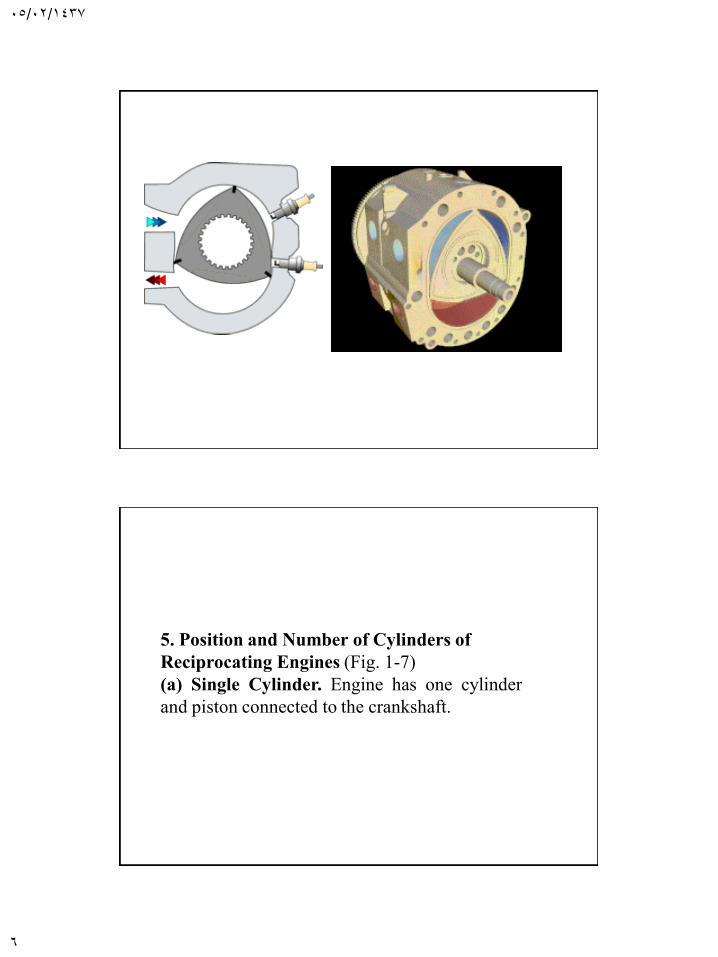
(b) Rotary. Engine is made of a block (stator) built
around a large non-concentric rotor and crankshaft.
The combustion chambers are built into the
nonrotating block.
05/02/1437
6
5. Position and Number of Cylinders of
Reciprocating Engines (Fig. 1-7)
(a) Single Cylinder. Engine has one cylinder
and piston connected to the crankshaft.
05/02/1437
7
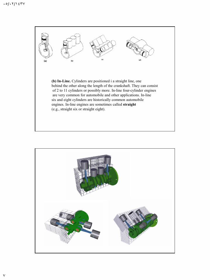
(b) In-Line. Cylinders are positioned i a straight line, one
behind the other along the length of the crankshaft. They can consist
of 2 to 11 cylinders or possibly more. In-line four-cylinder engines
are very common for automobile and other applications. In-line
six and eight cylinders are historically common automobile
engines. In-line engines are sometimes called straight
(e.g., straight six or straight eight).
05/02/1437
8
(c) V Engine. Two banks of cylinders at an angle with each other along a single
crankshaft. The angle between the banks of cylinders can be anywhere
from 15° to 120°, with 60°-90° being common. V engines have even numbers
of cylinders from 2 to 20 or more. V6s and V8s are common
automobile engines, with V12s and V16s (historic) found in some luxury
and high-performance vehicles.
(d) Opposed Cylinder Engine. Two banks of cylinders opposite each other on
a single crankshaft (a V engine with a 180°V). These are common on small
aircraft and some automobiles with an even number of cylinders from two
to eight or more. These engines are often called flat engines (e.g., flat
four).
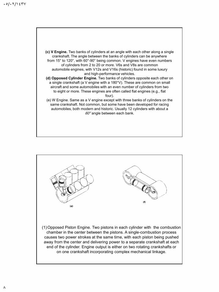
(e) W Engine. Same as a V engine except with three banks of cylinders on the
same crankshaft. Not common, but some have been developed for racing
automobiles, both modern and historic. Usually 12 cylinders with about a
60° angle between each bank.
(1)Opposed Piston Engine. Two pistons in each cylinder with the combustion
chamber in the center between the pistons. A single-combustion process
causes two power strokes at the same time, with each piston being pushed
away from the center and delivering power to a separate crankshaft at each
end of the cylinder. Engine output is either on two rotating crankshafts or
on one crankshaft incorporating complex mechanical linkage.
05/02/1437
9
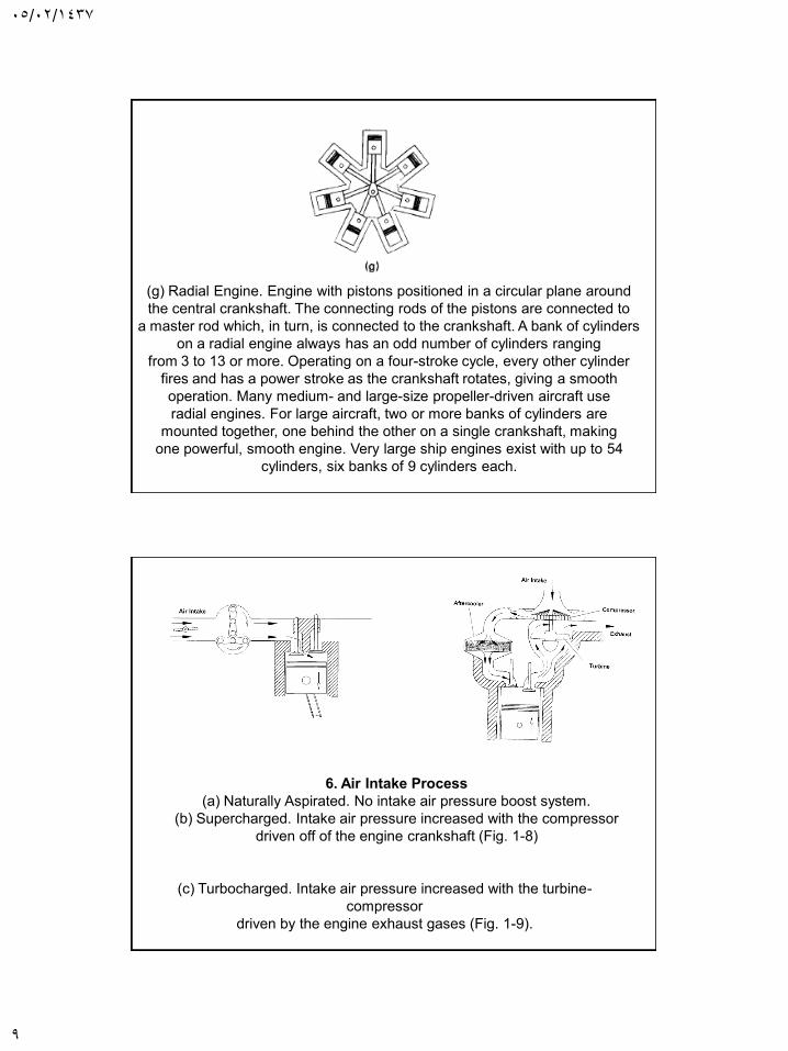
(g) Radial Engine. Engine with pistons positioned in a circular plane around
the central crankshaft. The connecting rods of the pistons are connected to
a master rod which, in turn, is connected to the crankshaft. A bank of cylinders
on a radial engine always has an odd number of cylinders ranging
from 3 to 13 or more. Operating on a four-stroke cycle, every other cylinder
fires and has a power stroke as the crankshaft rotates, giving a smooth
operation. Many medium- and large-size propeller-driven aircraft use
radial engines. For large aircraft, two or more banks of cylinders are
mounted together, one behind the other on a single crankshaft, making
one powerful, smooth engine. Very large ship engines exist with up to 54
cylinders, six banks of 9 cylinders each.
6. Air Intake Process
(a) Naturally Aspirated. No intake air pressure boost system.
(b) Supercharged. Intake air pressure increased with the compressor
driven off of the engine crankshaft (Fig. 1-8)
(c) Turbocharged. Intake air pressure increased with the turbine-
compressor
driven by the engine exhaust gases (Fig. 1-9).
05/02/1437
10
(d) Crankcase Compressed. Two-stroke cycle engine which uses the
crankcase as the intake air compressor. Limited development work
has also been done on design and construction of four-stroke cycle
engines with crankcase compression
7. Method of Fuel Input for SI Engines
(a) Carbureted.
(b) Multipoint Port Fuel Injection. One or more injectors at each cylinder
intake.
(c) Throttle Body Fuel Injection. Injectors upstream in intake manifold
8. Fuel Used
(a) Gasoline.
(b) Diesel Oil or Fuel Oil.
(c) Gas, Natural Gas, Methane.
(d) LPG.
(e) Alcohol-Ethyl, Methyl.
(f) Dual Fuel. There are a number of engines that use a combination of
two or more fuels. Some, usually large, CI engines use a combination
of methane and diesel fuel. These are attractive in developing third-
world countries because of the high cost of diesel fuel. Combined
gasoline-alcohol fuels are becoming more common as an alternative
to straight gasoline automobile engine fuel.
(g) Gasohol. Common fuel consisting of 90% gasoline and 10%
alcohol.
05/02/1437
11
9. Application
(a) Automobile, Truck, Bus.
(b) Locomotive.
(c) Stationary.
(d) Marine.
(e) Aircraft.
(f) Small Portable, Chain Saw, Model Airplane.
1O. Type of Cooling
(a) Air Cooled.
(b) Liquid Cooled, Water Cooled.
Several or all of these classifications can be used at the same time
to identify a given engine. Thus, a modern engine might be called a
turbocharged, reciprocating, spark ignition, four-stroke cycle, overhead
valve, water-cooled, gasoline, multipoint fuel-injected, V8 automobile
engine.
Spark Ignition (SI) An engine in which the combustion process in each
cycle is started by use of a spark plug.
Compression Ignition (CI) An engine in which the combustion process
starts when the air-fuel mixture self-ignites due to high temperature in the
combustion chamber caused by high compression. CI engines are often
called Diesel engines, especially in the non-technical community.
Top-Dead-Center (TDC) Position of the piston when it stops at the
furthest point away from the crankshaft. Top because this position is at the
top of most engines (not always), and dead because the piston stops at
this point. Because in some engines top-de ad-center is not at the top of
the engine (e.g., horizontally opposed engines, radial engines, etc.), some
Sources call this position
Bottom-Dead-Center (BDC) Position of the piston when it stops at the
point closest to the crankshaft. Some sources call this CrankEnd
Dead-Center (CEDC) because it is not always at the bottom of the
engine. Some sources call this point Bottom-Center (BC). During an
engine cycle things can happen before bottom-dead-center, bBDC or
bBC, and after bottom-de ad-center, aBDC or aBe.
05/02/1437
12
Bore Diameter of the cylinder or diameter of the piston face, which is
the same minus a very small clearance.
Stroke Movement distance of the piston from one extreme position to
the other: TDC to BDC or BDC to TDC.
Clearance Volume Minimum volume in the combustion chamber with
piston at TDC.
Displacement or Displacement Volume Volume displaced by the
piston as it travels through one stroke. Displacement can be given for
one cylinder or for the entire engine (one cylinder times number of
cylinders). Some literature calls this swept volume.
Air-Fuel Ratio (AF) Ratio of mass of air to mass of fuel input into
engine.
Fuel-Air Ratio (FA) Ratio of mass of fuel to mass of air input into
engine.
Brake Maximum Torque (BMT) Speed at which maximum torque
occurs.
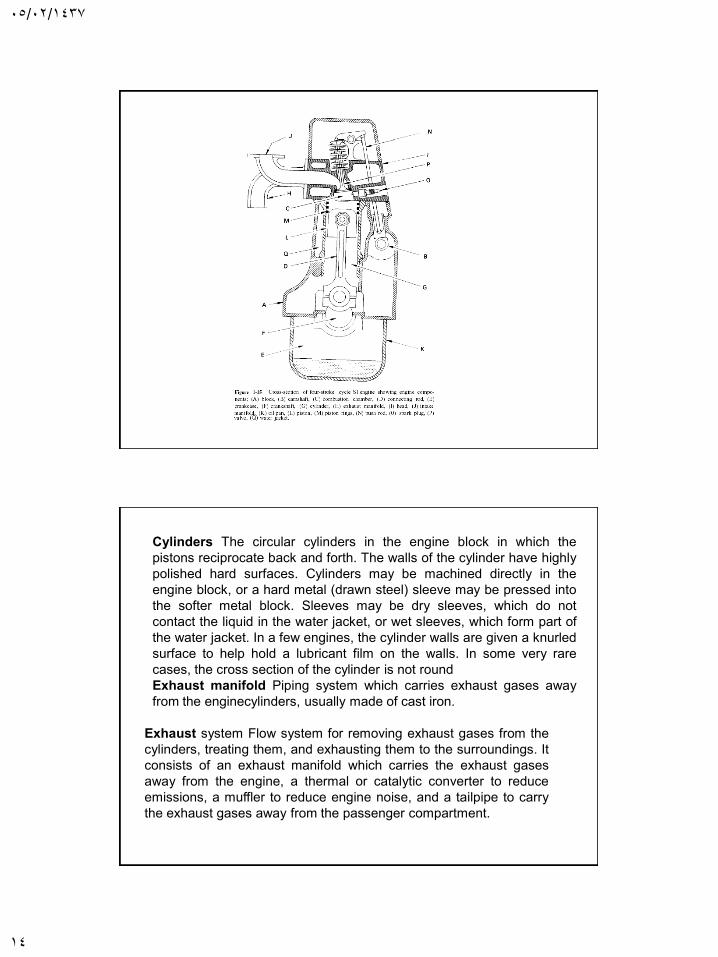
1-5 ENGINE COMPONENTS
The following is a list of major components found in most reciprocating
internal combustion engines (see Fig. 1-15).
Block Body of engine containing the cylinders, made of cast iron or
aluminum. In many older engines, the valves and valve ports were
contained in the block. The block of water-cooled engines includes a
water jacket cast around the cylinders. On air-cooled engines, the
exterior surface of the block has cooling fins.
Camshaft Rotating shaft used to push open valves at the proper time in
the engine cycle, either directly or through mechanical or hydraulic
linkage (push rods, rocker arms, tappets). Most modern automobile
engines have one or more camshafts mounted in the engine head
(overhead cam). Most older engines had camshafts in the crankcase.
Camshafts are generally made of forged steel or cast iron and are
driven off the crankshaft by means of a belt or chain (timing chain). To
reduce weight, some cams are made from a hollow shaft with the cam
lobes press-fit on. In four-stroke cycle engines, the camshaft rotates at
half engine speed.
05/02/1437
13
Carburetor Venturi flow device which meters the proper amount of fuel
into the air flow by means of a pressure differential. For many decades
it was the basic fuel metering system on all automobile (and other)
engines. It is still used on low cost small engines like lawn mowers, but
is uncommon on new automobiles.
Catalytic converter Chamber mounted in exhaust flow containing
catalytic material that promotes reduction of emissions by chemical
reaction.
Combustion chamber The end of the cylinder between the head and
the piston face where combustion occurs. The size of the combustion
chamber continuously changes from a minimum volume when the
piston is at TDC to a maximum when the piston is at BDC. The term
"cylinder" is sometimes synonymous with "combustion chamber" (e.g.,
"the engine was firing on all cylinders"). Some engines have open combustion chambers which consist of one chamber for each
cylinder. Other engines have divided chambers which consist of dual
chambers on each cylinder connected by an orifice passage.
Connecting rod: Rod connecting the piston with the rotating
crankshaft, usually made of steel or alloy forging in most engines but
may be aluminum in some small engines.
Connecting rod bearing Bearing where connecting rod fastens to
crankshaft.
Cooling fins Metal fins on the outside surfaces of cylinders and head
of an aircooled engine. These extended surfaces cool the cylinders by
conduction andconvection
Crankshaft Rotating shaft through which engine work output is
supplied to external systems. The crankshaft is connected to the
engine block with the main bearings. It is rotated by the reciprocating
pistons through connecting rods connected to the crankshaft, offset
from the axis of rotation. This offset issometimes called crank throw or crank radius. Most crankshafts are made of forged steel, while
some are made of cast iron.
05/02/1437
14
Cylinders The circular cylinders in the engine block in which the
pistons reciprocate back and forth. The walls of the cylinder have highly
polished hard surfaces. Cylinders may be machined directly in the
engine block, or a hard metal (drawn steel) sleeve may be pressed into
the softer metal block. Sleeves may be dry sleeves, which do not
contact the liquid in the water jacket, or wet sleeves, which form part of
the water jacket. In a few engines, the cylinder walls are given a knurled
surface to help hold a lubricant film on the walls. In some very rare
cases, the cross section of the cylinder is not round
Exhaust manifold Piping system which carries exhaust gases away
from the enginecylinders, usually made of cast iron.
Exhaust system Flow system for removing exhaust gases from the
cylinders, treating them, and exhausting them to the surroundings. It
consists of an exhaust manifold which carries the exhaust gases
away from the engine, a thermal or catalytic converter to reduce
emissions, a muffler to reduce engine noise, and a tailpipe to carry
the exhaust gases away from the passenger compartment.
05/02/1437
15
Fan Most engines have an engine-driven fan to increase air flow through
the radiator and through the engine compartment, which increases waste
heat removal from the engine. Fans can be driven mechanically or
electrically, and can run continuously or be used only when needed.
Flywheel Rotating mass with a large moment of inertia connected to the
crankshaft of the engine. The purpose of the flywheel is to store energy
and furnish a large angular momentum that keeps the engine rotating
between power strokes and smoothes out engine operation. On some
aircraft engines the propeller serves as the flywheel, as does the rotating
blade on many lawn mowers.
Fuel injector A pressurized nozzle that sprays fuel into the incoming air
on SI engines or into the cylinder on CI engines. On SI engines, fuel
injectors are located at the intake valve ports on multipoint port injector
systems and upstream at the intake manifold inlet on throttle body
injector systems. In a few SI engines, injectors spray directly into the
combustion chamber.
Fuel pump Electrically or mechanically driven pump to
supply fuel from the fuel tank (reservoir) to the engine. Many
modern automobiles have an electric fuel pump mounted
submerged in the fuel tank. Some small engines and early
automobiles had no fuel pump, relying on gravity feed.
05/02/1437
16
1-6 BASIC ENGINE CYCLES
Most internal combustion engines, both spark ignition and
compression ignition, operate on either a four-stroke cycle or a
two-stroke cycle. These basic cycles are fairly standard for all
engines, with only slight variations found in individual designs
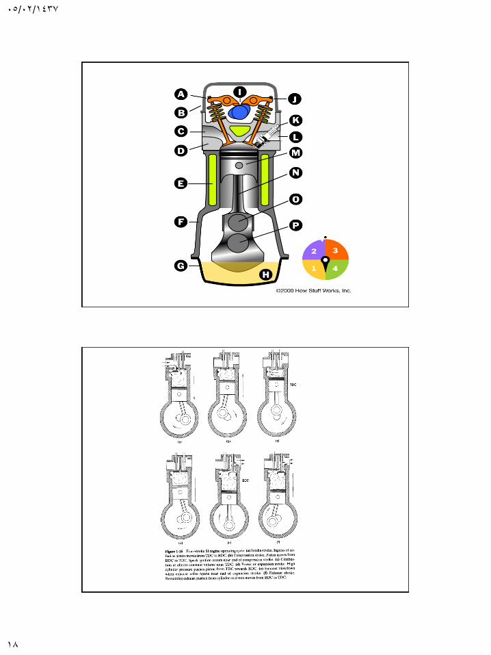
Four-Stroke SI Engine Cycle (Fig. 1-16)
1. First Stroke: Intake Stroke or Induction The piston travels
from TDC to BDC with the intake valve open and exhaust valve
closed. This creates an increasing volume in the combustion
chamber, which in turn creates a vacuum. The resulting
pressure differential through the intake system from atmospheric
pressure on the outside to the vacuum on the inside causes air
to be pushed into the cylinder. As the air passes through the
intake system, fuel is added to it in the desired amount by
means of fuel injectors or a carburetor.
2. Second Stroke: Compression Stroke When the piston reaches
BDC, the intake valve closes and the piston travels back to TDC with all
valves closed. This compresses the air-fuel mixture, raising both the
pressure and temperature in the cylinder. The finite time required to
close the intake valve means that actual compression doesn't start until
sometime aBDC. Near the end of the compression stroke, the spark plug
is fired and combustion is initiated.
3. Combustion Combustion of the air-fuel mixture occurs in a very short
but finite length of time with the piston near TDC (i.e., nearly constant-
volume combustion). It starts near the end of the compression stroke
slightly bTDC and lasts into the power stroke slightly aTDC. Combustion
changes the composition of the gas mixture to that of exhaust products
and increases the temperature in the cylinder to a very high peak value.
This, in turn, raises the pressure in the cylinder to a very high peak
value.
05/02/1437
17
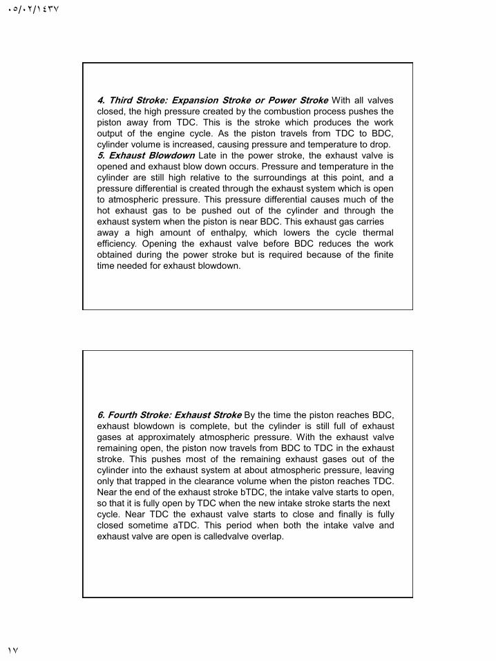
4. Third Stroke: Expansion Stroke or Power Stroke With all valves
closed, the high pressure created by the combustion process pushes the
piston away from TDC. This is the stroke which produces the work
output of the engine cycle. As the piston travels from TDC to BDC,
cylinder volume is increased, causing pressure and temperature to drop.
5. Exhaust Blowdown Late in the power stroke, the exhaust valve is
opened and exhaust blow down occurs. Pressure and temperature in the
cylinder are still high relative to the surroundings at this point, and a
pressure differential is created through the exhaust system which is open
to atmospheric pressure. This pressure differential causes much of the
hot exhaust gas to be pushed out of the cylinder and through the
exhaust system when the piston is near BDC. This exhaust gas carries
away a high amount of enthalpy, which lowers the cycle thermal
efficiency. Opening the exhaust valve before BDC reduces the work
obtained during the power stroke but is required because of the finite
time needed for exhaust blowdown.
6. Fourth Stroke: Exhaust Stroke By the time the piston reaches BDC,
exhaust blowdown is complete, but the cylinder is still full of exhaust
gases at approximately atmospheric pressure. With the exhaust valve
remaining open, the piston now travels from BDC to TDC in the exhaust
stroke. This pushes most of the remaining exhaust gases out of the
cylinder into the exhaust system at about atmospheric pressure, leaving
only that trapped in the clearance volume when the piston reaches TDC.
Near the end of the exhaust stroke bTDC, the intake valve starts to open,
so that it is fully open by TDC when the new intake stroke starts the next
cycle. Near TDC the exhaust valve starts to close and finally is fully
closed sometime aTDC. This period when both the intake valve and
exhaust valve are open is calledvalve overlap.
05/02/1437
18
05/02/1437
19
Stroke CI Engine Cycle-Four
1. First Stroke: Intake Stroke The same as the intake stroke in an SI
engine with one major difference: no fuel is added to the incoming
air.
2. Second Stroke: Compression Stroke The same as in an SI engine
except that only air is compressed and compression is to higher
pressures and temperature. Late in the compression stroke fuel is
injected directly into the combustion chamber, where it mixes with
the very hot air. This causes the fuel to evaporate and self-ignite,
causing combustion to start.
3. Combustion Combustion is fully developed by TDC and
continues atabout constant pressure until fuel injection is complete
and the piston has started towards BDC.
4. Third Stroke: Power Stroke The power stroke continues as
combustion ends and the piston travels towards BDC.
5. Exhaust Blowdown Same as with an SI engine.
6. Fourth Stroke: Exhaust Stroke Same as with an SI engine.


![Point-to-Multipoint and Multipoint-to-Multipoint · PDF filedefined by IEEE 802.1Qay [2] is representative carrier Ethernet . Abstract — We have implemented point-to-multipoint (PtMP)](https://img.pdfslide.net/doc/110x75/5a75c0147f8b9a4b538cb6cd/point-to-multipoint-and-multipoint-to-multipoint-defined-by-ieee-8021qay.jpg)