Embed Size (px)
Citation preview

Chapter 1, slide: 1
Spring 2014ECE/CS 372 Introduction to Computer
Networks
Lecture 1
School of Electrical Engineering and Computer ScienceOregon State University
Course Overview
Credit for lecture slides to Professor Bechir Hamdaoui Adapted from Jim Kurose & Keith Ross (original copyright)

Chapter 1, slide: 2
Course website http://classes.engr.oregonstate.edu/eecs/spring2014/cs372-001/
Please write down this URL—all course material and information will be provided thru this site
Lectures Tuesday, Thursday 12:00-1:20pm, 212 Kearney Hall
Instructor Stephen Redfield ([email protected])
Office hours: TR 1:30-2:30pm @ Kelley Engineering Center Rm 2077
Lecture/Office/Lab Hours

Chapter 1, slide: 3
Tamara AlShammariLocation: KEC 2063Lab hours: to help you with your labsHours TBD
Information can be found in course’s website
MohammadJavad NoroozOliaee (MJ)Location: KEC 2063Office hours: to help you with your assignmentsHours TBD
Information can be found in course’s website
Lecture/Office/Lab Hours

Chapter 1, slide: 4
Prerequisite: CS or ECE 271 or an equivalent course Basic mathematical/probability skills
Textbook
Prerequisite/Textbook
Textbook is RequiredComputer Networking: A Top-Down Approach Featuring the Internet, 6th Edition, Games F. Kurose, Keith W. Ross

Chapter 1, slide: 5
Grading Policy Assignments: 15%
Each student must hand in one copy 5 assignments: approx. 1 every two weeks Check, Check Minus, X Grading
Labs: 20% Each student must hand in one copy 4 labs: approx. 1 every two weeks
Bonus pop quizzes: extra 2 to 10% You need to get it completely right to receive an extra 1%
One midterm exam: 30% Final exam: 35%

Chapter 1, slide: 6
Lectures & assignments
Objective Deep understanding of basic and fundamental
networking concepts, architectures, and philosophies
IMPORTANT: this course is not about setting up your router at home, or writing a twitter program!!
Approach: how to do well in this course Easy: attend ALL lectures and do ALL assignments Do your assignments individually (Don’t use
Solutions) Do NOT miss any Bonus Quiz (i.e., do not miss class) Some HW problems will be solved in class: this gives
you the opportunity to clarify things further
Chapter 1, slide: 7
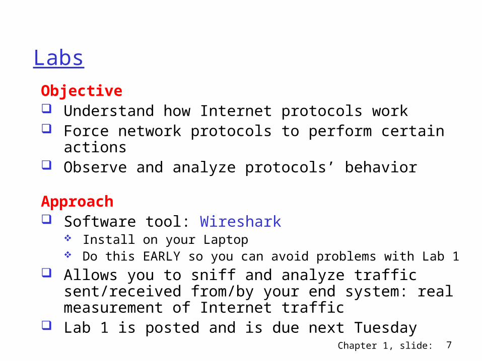
Labs
Objective Understand how Internet protocols work Force network protocols to perform certain
actions Observe and analyze protocols’ behavior
Approach Software tool: Wireshark
Install on your Laptop Do this EARLY so you can avoid problems with Lab 1
Allows you to sniff and analyze traffic sent/received from/by your end system: real measurement of Internet traffic
Lab 1 is posted and is due next Tuesday

Chapter 1, slide: 8
Break Online Course Available
We’ll start after a 10-min break

Chapter 1, slide: 9
Chapter 1: Introduction
Our goal: learn basic network
terminologies more depth, detail
later in course approach:
use Internet as example
Acknowledgement: slides drawn heavily from Kurose & Ross
Chapter 1, slide: 10
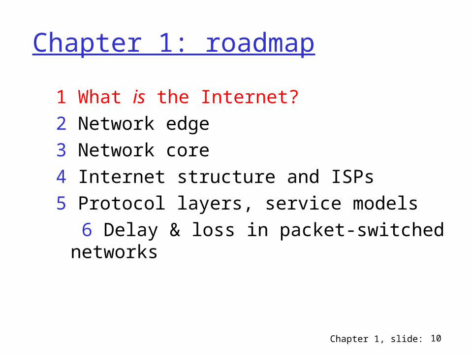
Chapter 1: roadmap
1 What is the Internet?2 Network edge3 Network core4 Internet structure and ISPs5 Protocol layers, service models
6 Delay & loss in packet-switched networks

Chapter 1, slide: 11
What’s the Internet: a “service” view communication
infrastructure enables distributed apps: Enables apps to
communicate Web, email, games, e-
commerce, file sharing
communication services provided to apps: Offers services

Chapter 1, slide: 12
What’s the Internet: “nuts and bolts” view
hosts or end systems: millions of connected computing devices e.g., Laptops,
workstations running network apps
routers & switches: forward packets (chunks
of data)
communication links e.g., fiber, copper, radio,
satellite
local ISP
companynetwork
regional ISP
router workstation
servermobile

Chapter 1, slide: 13
What’s the Internet: “nuts and bolts” view Internet standards
IETF (Internet Eng. Task Force)
• RFC: Request for comments
IEEE: for links/hardware E.g., Ethernet
network protocols control sending/receiving
of messages e.g., TCP, IP, HTTP, FTP,
PPP
local ISP
companynetwork
regional ISP
router workstation
servermobile

Chapter 1, slide: 14
What’s a protocol?a human protocol and a computer network protocol:
Hi
Hi
Got thetime?
2:00
TCP connection request
TCP connectionresponseGet http://www.awl.com/kurose-ross
<file>time

Chapter 1, slide: 15
What’s a protocol?human protocols: “What’s the time?” “I have a question” introductions
… specific msgs sent… specific actions
taken when msgs received, or other events
network protocols: machines rather than
humans all communication
activity in Internet governed by protocols
protocols define (1) format, order of msgs sent and
received among network entities, and (2) actions
taken on msg transmission, receipt

Chapter 1, slide: 16
Chapter 1: roadmap
1 What is the Internet?2 Network edge3 Network core4 Internet structure and ISPs 5 Protocol layers, service models
6 Delay & loss in packet-switched networks

Chapter 1, slide: 17
A closer look at network structure: network edge:
applications and hosts network core:
routers network of networks
access networks, physical media: communication links
Chapter 1, slide: 18
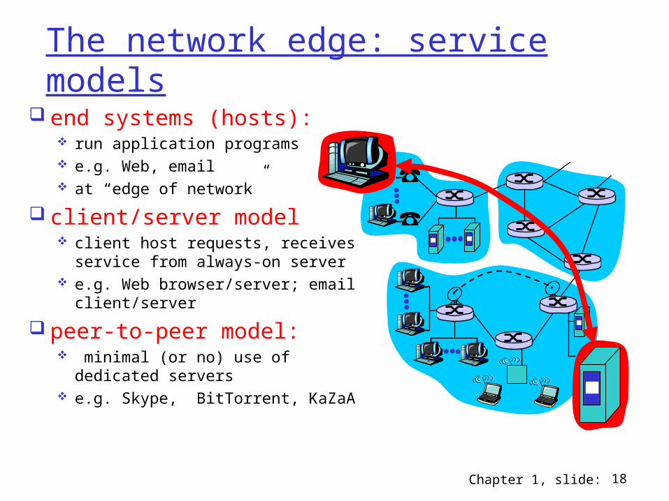
The network edge: service models
end systems (hosts): run application programs e.g. Web, email at “edge of network”
client/server model client host requests, receives
service from always-on server e.g. Web browser/server; email
client/server
peer-to-peer model: minimal (or no) use of
dedicated servers e.g. Skype, BitTorrent, KaZaA

Chapter 1, slide: 19
Chapter 1: roadmap
1 What is the Internet?2 Network edge3 Network core4 Internet structure and ISPs5 Protocol layers, service models
6 Delay & loss in packet-switched networks

Chapter 1, slide: 20
The Network Core
mesh of interconnected routers
the fundamental question:
how is data transferred through net? circuit switching:
dedicated circuit per call: telephone net
packet-switching: data sent thru net in discrete “chunks”

Chapter 1, slide: 21
Network Core: Circuit Switching
End-end resources reserved for “call”
dedicated resources: no sharing
call setup required circuit-like
(guaranteed) performance
same path for all chunks

Chapter 1, slide: 22
Network Core: Circuit Switching
network resources (e.g., bandwidth) divided into “pieces”
allocated pieces per call
no sharingresource piece idle if not used by owning call

Chapter 1, slide: 23
Network Core: Circuit Switching
Two ways of dividing bandwidth into “pieces” frequency division time division

Chapter 1, slide: 24
Circuit Switching: FDM and TDM
Freq. Division Multiplx. (FDM)
frequency
time
Time Division Multiplx. (TDM)
frequency
time
4 users
Example:

Chapter 1, slide: 25
Network Core: Packet Switching
each end-to-end data stream is divided into packets no dedication/reservation: all streams share resources
no setup is required resources used as needed each packet uses full link bandwidth aggregate resource demand can exceed capacity no guarantee
A
B
C100 Mb/sEthernet
1.5 Mb/s

Chapter 1, slide: 26
Sequence of A & B packets does not have fixed pattern, shared on demand statistical multiplexing.
Whereas in TDM, each host gets same slot (periodically)
A
B
C100 Mb/sEthernet
1.5 Mb/s
D E
statistical multiplexing
queue of packetswaiting for output
link
Network Core: statistical multiplexing

Chapter 1, slide: 27
A
B2 Mb/s
Circuit switching
B: has nopackets to send
• 2 circuits (use TDM)• A reserves 1 circuit• B reserves 1 circuit
A
B2 Mb/s
Packet switching
• statistical multiplex.• B uses full link since A is not using it
Packet switching versus circuit switching
Utilization = 50% only = 1 Mb/s
Utilization = 100% = 2 Mb/s

Chapter 1, slide: 28
Packet switching versus circuit switching
Packet-switching Circuit-switching
Resources sharing dedicated
Congestion may lead to it admission control
Overhead less overhead; more overhead;
no connection setup reserve resources 1st
Guarantee Best-effort provide guarantee
no guarantee good for multimedia

Chapter 1, slide: 29
Numerical example
How long does it take to send a file of 640,000 bits from host A to host B over a circuit-switched network? The link’s transmission rate = 0.64 Mbps The link uses the following TDM scheme
• One frame per second• 10 slots per frame (so we can accommodate up to 10
hosts) 0.5 sec to establish end-to-end circuit
Let’s work it out! You have few minutes! Solution: Bandwidth of circuit (in kbps)= .64x1000/10 = 64
kbps Time to send: 640 kbits/64 kbps + 0.5s = 10.5s

Chapter 1, slide: 30
ECE/CS 372 – Introduction to Computer Networks
Lecture 2
Announcements:
Please make sure to check the course’s website on a regular basis
http://classes.engr.oregonstate.edu/eecs/spring2014/cs372-001/
Unit Metrics – Let’s Sidestep the issue!
Credit for lecture slides to Professor Bechir Hamdaoui Adapted from Jim Kurose & Keith Ross (original copyright)

Chapter 1, slide: 31
Packet switching versus circuit switching
Packet-switching Circuit-switching
Resources sharing dedicated
Congestion may lead to it admission control
Overhead less overhead; more overhead;
no connection setup reserve resources 1st
Guarantee Best-effort provide guarantee
no guarantee good for multimedia
Chapter 1, slide: 32
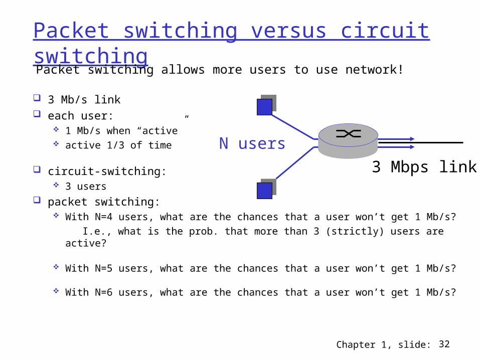
Packet switching versus circuit switching
3 Mb/s link each user:
1 Mb/s when “active” active 1/3 of time
circuit-switching: 3 users
packet switching: With N=4 users, what are the chances that a user won’t get 1 Mb/s? I.e., what is the prob. that more than 3 (strictly) users are active?
With N=5 users, what are the chances that a user won’t get 1 Mb/s?
With N=6 users, what are the chances that a user won’t get 1 Mb/s?
Packet switching allows more users to use network!
N users
3 Mbps link

Chapter 1, slide: 33
Packet switching versus circuit switchingBoard …

Chapter 1, slide: 34
ECE/CS 372 – Introduction to Computer Networks
Lecture 3
Announcements:
Assign 1 will be posted today and due in a week from now.
Credit for lecture slides to Professor Bechir Hamdaoui Adapted from Jim Kurose & Keith Ross (original copyright)

Chapter 1, slide: 35
Chapter 1: roadmap
1 What is the Internet?2 Network edge3 Network core4 Internet structure and ISPs5 Protocol layers, service models
6 Delay & loss in packet-switched networks

Chapter 1, slide: 36
Internet structure: network of networks
roughly hierarchical: tier 1, tier 2, and tier 3 at center: “tier-1” ISPs
e.g., MCI, Sprint, AT&T, Cable and Wireless, national/international coverage
Tier 1 ISP
Tier 1 ISP
Tier 1 ISP
Tier-1 providers interconnect (peer) privately
NAP
Tier-1 providers also interconnect at public network access points (NAPs)
IXP
Network interconnects handled at Internet Exchange Points (IXP)
Chapter 1, slide: 37
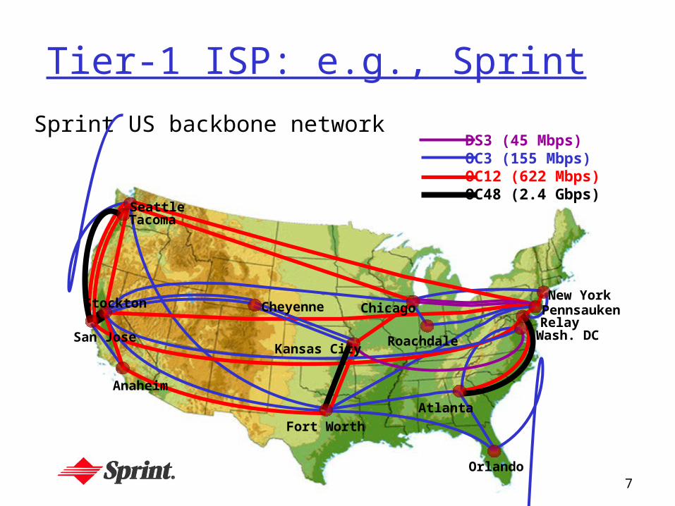
Tier-1 ISP: e.g., Sprint
Sprint US backbone network
Seattle
Atlanta
Chicago
Roachdale
Stockton
San Jose
Anaheim
Fort Worth
Orlando
Kansas City
CheyenneNew York
PennsaukenRelay
Wash. DC
Tacoma
DS3 (45 Mbps)OC3 (155 Mbps)OC12 (622 Mbps)OC48 (2.4 Gbps)

Chapter 1, slide: 38
Internet structure: network of networks
“Tier-2” ISPs: smaller (often regional) ISPs Connect to one or more tier-1 ISPs, possibly other tier-2 ISPs
Tier 1 ISP
Tier 1 ISP
Tier 1 ISP
IXP
Tier-2 ISPTier-2 ISP
Tier-2 ISP Tier-2 ISP
Tier-2 ISP
Tier-2 ISP is customer oftier-1 provider
Tier-2 ISPs also peer privately with each other, interconnect at IXP

Chapter 1, slide: 39
Internet structure: network of networks
“Tier-3” ISPs and local ISPs last hop (“access”) network (closest to end systems)
Tier 1 ISP
Tier 1 ISP
Tier 1 ISP
IXP
Tier-2 ISPTier-2 ISP
Tier-2 ISP Tier-2 ISP
Tier-2 ISP
localISPlocal
ISPlocalISP
localISP
localISP Tier 3
ISP
localISP
localISP
localISP
Local and tier- 3 ISPs are customers ofhigher tier ISPsconnecting them to rest of Internet

Chapter 1, slide: 40
Internet structure: network of networks
a packet passes through many networks!
Tier 1 ISP
Tier 1 ISP
Tier 1 ISP
IXP
Tier-2 ISPTier-2 ISP
Tier-2 ISP Tier-2 ISP
Tier-2 ISP
localISPlocal
ISPlocalISP
localISP
localISP Tier 3
ISP
localISP
localISP
localISP

Chapter 1, slide: 41
Chapter 1: roadmap
1 What is the Internet?2 Network edge3 Network core4 Internet structure and ISPs5 Protocol layers, service models6 Delay & loss in packet-switched
networks

Chapter 1, slide: 42
Protocol “Layers”Networks are
complex! many “pieces”:
hosts routers links of various
media applications protocols hardware,
software
Question: Is there any hope of an
organizing structure of network?
Chapter 1, slide: 43
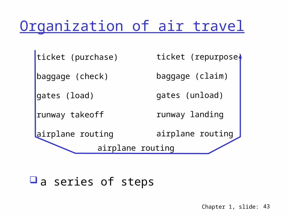
Organization of air travel
a series of steps
ticket (purchase)
baggage (check)
gates (load)
runway takeoff
airplane routing
ticket (repurpose)
baggage (claim)
gates (unload)
runway landing
airplane routing
airplane routing

Chapter 1, slide: 44
ticket (purchase)
baggage (check)
gates (load)
runway (takeoff)
airplane routing
departureairport
arrivalairport
intermediate air-trafficcontrol centers
airplane routing airplane routing
ticket (complain)
baggage (claim
gates (unload)
runway (land)
airplane routing
ticket
baggage
gate
takeoff/landing
airplane routing
Layering of airline functionality
Layers: each layer implements a service via its own internal-layer actions relying on services provided by layer below

Chapter 1, slide: 45
Why layering?
Dealing with complex systems:
Easing assignment of tasks identify relationship among pieces of
complex systems
Easing maintenance, updating of system change of implementation of layer’s service
transparent to rest of system e.g., change in gate procedure doesn’t
affect rest of system

Chapter 1, slide: 46
Internet protocol stack application: supporting network
applications FTP, SMTP, HTTP
transport: process-process data transfer TCP, UDP
network: routing of datagrams from source to destination IP, routing protocols
link: data transfer between neighboring network elements PPP, Ethernet
physical: bits “on the wire”
application
transport
network
link
physical

Chapter 1, slide: 47
sourceapplicatio
ntransportnetwork
linkphysical
HtHn M
segment Ht
datagram
destination
application
transportnetwork
linkphysical
HtHnHl M
HtHn M
Ht M
M
networklink
physical
linkphysical
HtHnHl M
HtHn M
HtHn M
HtHnHl M
router
switch
Encapsulationmessage M
Ht M
Hn
frame

Chapter 1, slide: 48
ISO/OSI Model: late 70’s
application
transport
network
link
physical
presentation
application
session
transport
network
data link
physical
7-layer ISO/OSI model(OSI: open system interconnections)
5-layer Internet Protocol Stack

Chapter 1, slide: 49
Chapter 1: roadmap
1 What is the Internet?2 Network edge3 Network core4 Internet structure and ISPs 5 Protocol layers, service models6 Delay & loss in packet-switched
networks

Chapter 1, slide: 50
Sources of packet delay
1. processing: check bit errors determine output link
2. queueing time waiting at output
link for transmission depends on
congestion level of router
A
Bnodal
processing queueing

Chapter 1, slide: 51
3. Transmission delay: R=link bandwidth (bps) L=packet length (bits) trans. delay = L/R
4. Propagation delay: d = length of physical link s = propagation speed in
medium (~2x10⁸ m/sec) propagation delay = d/s
Note: s and R are very different quantities!
A
B
propagation
transmission
nodalprocessing queueing
Sources of packet delay

Chapter 1, slide: 52
Caravan analogy
Cars run at 100 km/hr (speed of propagation)
Booth takes 12 sec to service a car (transmission time)
Car ~ bit; caravan ~ packet
Q: How long until caravan is lined up before 2nd toll booth?
Time to “push” entire caravan through toll booth = 12*10 = 120 sec = 2 mns
Time for last car to propagate from 1st to 2nd toll both: =100km/(100km/hr)= 1 hr
A: 1 hr 2 minutes
toll booth
toll booth
ten-car caravan
100 km
100 km

Chapter 1, slide: 53
Caravan analogy (more)
Cars now “propagate” at 1000 km/hr
Toll booth now takes 1 min to service a car
Q: Will cars arrive to 2nd booth before all cars serviced at 1st booth?
Yes! After 7 min, 1st car at 2nd booth and 8th car still at 1st booth.
1st bit of packet can arrive at 2nd router before packet is fully transmitted at 1st router!
toll booth
toll booth
ten-car caravan
100 km
100 km

Chapter 1, slide: 54
Exercise 1
Host A Host Btrans. rate R = 1 Mbps
distance = 1 km, speed = 2x10⁸m/s
Packet length = L bits
Question: Which bit is being transmitted at the time the first bit
arrives at Host B for
Answer:First bit arrives after 1/R + d/s = 1/106 + 103/(2x108) = 10-6 + 5x10-6 = 6x10-6 =
6 µsec
After 6 µsec6 bits are already transmitted; so 7th bit is being transmitted

Chapter 1, slide: 55
Exercise 2Transmission vs. propagation
Host A Host Btrans. rate R = ?
distance = 2 km, speed = 2x10⁸m/s
L=100Bytes
Question: At what rate (bandwidth) R would the propagation delay
equal the transmission delay of packet?
Answer: Propagation delay = 2x10³ (m)/2x108 (m/s) = 10-5 sec Transmission delay = 100x8 (bits)/R Prop. delay = trans. delay => R=105x100x8 = 80 Mbps

Chapter 1, slide: 56
Exercise 3Voice over IP
Host A Host Btrans. rate R = 1Mbps
delay_prop = 2mseca=64Kbps
L=48 Bytes
Host A converts analog to digital at a=64Kbps groups bits into L=48Byte packets sends packet to Host B as soon it gathers a packet
Host B As soon as it receives the whole pckt, it converts it to analog
Question: How much time elapses from the 1st bit of 1st packet is
created until the last bit of the 1st packet arrives at Host B?

Chapter 1, slide: 57
Exercise 3Voice over IP
Host A Host Btrans. rate R = 1Mbps
delay_prop = 2msec
Answer: Time to gather 1st pkt: 48x8 (bits)/64x1000 (b/s) = 6 msec
Time to push 1st pkt to link: 48x8 (bits)/1x106 (b/s) = 0.384 msec
Time to propagate: 2 msec
Total delay = 6 + 0.384 + 2 = 8.384 msec
a=64Kbps
L=48 Bytes

Chapter 1, slide: 58
ECE/CS 372 – introduction to computer networks
Lecture 4
Announcements: Assign 1 is due next Tuesday
Credit for lecture slides to Professor Bechir Hamdaoui Adapted from Jim Kurose & Keith Ross (original copyright)

Chapter 1, slide: 59
Nodal delay
dproc = processing delay typically a few microsecs or less
dqueue = queuing delay depends on congestion
dtrans = transmission delay = L/R, significant for low-speed links
dprop = propagation delay a few microsecs to hundreds of msecs
proptransqueueprocnodal ddddd

Chapter 1, slide: 60
Queueing delay (more insight)
Every second: aL bits arrive to queue Every second: R bits leave the router Question: what happens if aL > R ? Answer: queue will fill up, and packets will get
dropped!!
aL/R is called traffic intensity
queuePacket arrival rate= a packets/sec
Link bandwidth = R bits/sec
Packet length = L bits

Chapter 3, slide: 61
Queueing delay: illustration
Arrival rate: a = 1/(L/R) = R/L (packet/second)
Traffic intensity = aL/R = (R/L) (L/R) = 1
Average queueing delay = 0(queue is initially empty)
queueLink bandwidth = R bits/sec
1 packet arrivesevery L/R seconds
Packet length L bits

Chapter 3, slide: 62
Queueing delay: illustration
Arrival rate: a = N/(LN/R) = R/L packet/second
Traffic intensity = aL/R = (R/L) (L/R) = 1
Average queueing delay (queue is empty is time 0) ?{0 + L/R + 2L/R + … + (N-1)L/R}/N = L/(RN){1+2+…+(N-1)} =L(N-1)/(2R)Note: traffic intensity is same as previous scenario, but queueing delay is different
queueLink bandwidth = R bits/sec
N packet arrive simultaneouslyevery LN/R seconds
Packet length L bits

Chapter 1, slide: 63
Queueing delay: behavior
La/R ~ 0: avg. queueing delay small
La/R -> 1: delays become large La/R > 1: more “work” than can
be serviced, average delay infinite!
(this is when a is random!)
queuePacket arrival rate= a packets/sec
Link bandwidth = R bits/sec
Packet length = L bits
Chapter 1, slide: 64
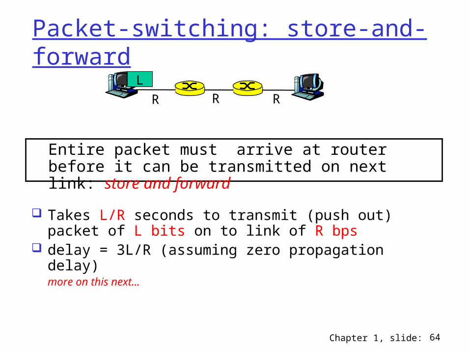
Packet-switching: store-and-forward
Takes L/R seconds to transmit (push out) packet of L bits on to link of R bps
delay = 3L/R (assuming zero propagation delay)more on this next…
R R RL
Entire packet must arrive at router before it can be transmitted on next link: store and forward

Chapter 1, slide: 65
Store-and-forward: illustration
delay (one packet only) = L/R + d/s
R
L d
distance = d meters; speed of propagation = s m/sec transmission rate of link = R bits/s
delay (one packet only) = L/R + ½d/s + L/R + ½d/s = 2L/R + d/s
Example:d/s = 0.5 secL = 10 MbitsR = 1 Mbpsdelay = 10.5 sec
Example:d/s = 0.5 secL = 10 MbitsR = 1 Mbpsdelay = 20.5 sec
R R
Ld/2 d/2

Chapter 1, slide: 66
Store-and-forward & queuing delay
Case 1: Assume R1 < R2
distance = d meters; speed of propagation = s m/sec transmission rate of link = R1 and R2 bits/s Consider sending two packets A and B back to back
R1 R2
Ld
Case 2: Assume R1 > R2
Q: is there a queuing delay? how much is this delay?Answer (queue is empty initially):
Time for last bit of 2nd pkt to arrive at router: d1= L/R1 + L/R1 + d/(2s)Time for last bit of 1st pkt to leave router: d2= L/R1 + d/(2s) + L/R2Queueing delay = d2 – d1 = L/R2 – L/R1 if positive, otherwise 0. Hence:when R1 < R2, queueing delay = d2 – d1 = 0when R1 > R2, queueing delay = d2 – d1 = L/R2 – L/R1

Chapter 1, slide: 67
Throughput analysis
Suppose: Host A has huge file of size F bits to send to Host B File is split into N packets, each of length L bits (i.e., N=F/L) Ignore propagation delay for now
R R RLHost A Host B
Question 1: how long it takes to send the file?A: (N+2)L/R = (F+2L)/R
Question 2: what is the average throughput achieved when sending the file?A: NL/[(N+2)L/R]=NR/(N+2) = FR/(F+2L) = R/(1+2L/F)
Note: throughput = number of total bits sent / total time taken

Chapter 1, slide: 68
Throughput analysis
Suppose: Host A has huge file of size F bits to send to Host B File is split into N packets, each of length L bits (i.e., N=F/L) Do NOT ignore propagation delay (assume prop. speed = s m/s)
R R RLHost A Host B
Question 1: how long it takes to send the file?A: (N+2)L/R + d/s = (F+2L)/R + d/s
Question 2: what is the average throughput achieved when sending the file?A: NL/[(N+2)L/R +d/s]=FR/[(N+2)L + dR/s] = FR/[F+2L+dR/s]
d/3 d/3d/3

Chapter 1, slide: 69
Introduction: Summary
Covered a ton of material! Internet overview Network protocol Network edge, core, access network Packet-switching versus circuit-switching Internet/ISP structure layering and service models performance: delay and throughput
analysis