Embed Size (px)
Citation preview
Chapter 11 I/O Systems 1
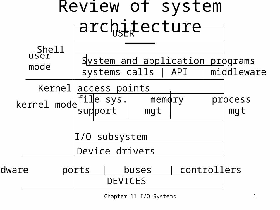
Review of system architecture
user mode
kernel mode
USER
Shell System and application programs systems calls | API | middleware
Kernel access points file sys. memory process support mgt mgt
I/O subsystem
Device drivers
Hardware ports | buses | controllers DEVICES
Chapter 11 I/O Systems 2
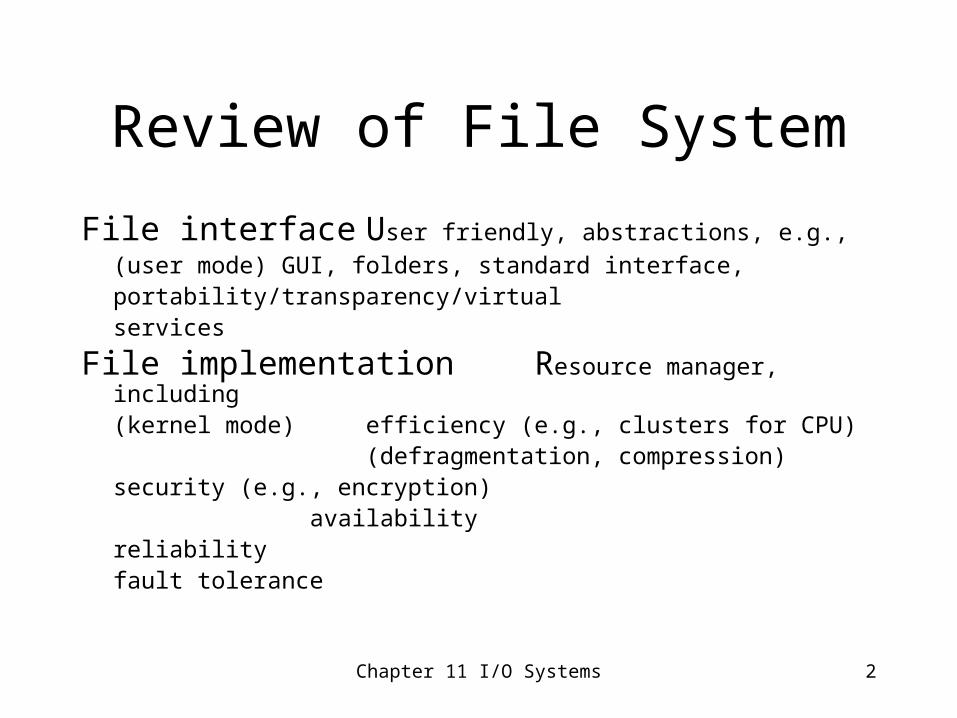
Review of File System
File interface User friendly, abstractions, e.g.,
(user mode) GUI, folders, standard interface,portability/transparency/virtualservices
File implementation Resource manager, including
(kernel mode) efficiency (e.g., clusters for CPU) (defragmentation, compression)
security (e.g., encryption) availability
reliability fault tolerance
Chapter 11 I/O Systems 3
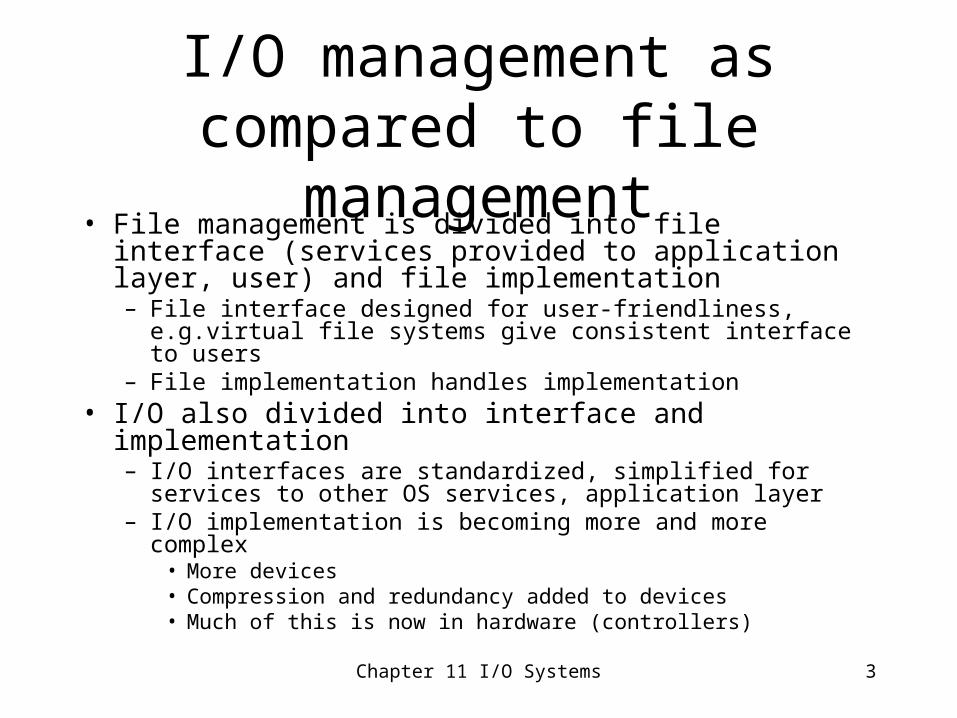
I/O management as compared to file management
• File management is divided into file interface (services provided to application layer, user) and file implementation– File interface designed for user-friendliness, e.g.virtual file
systems give consistent interface to users– File implementation handles implementation
• I/O also divided into interface and implementation– I/O interfaces are standardized, simplified for services to other OS
services, application layer– I/O implementation is becoming more and more complex
• More devices• Compression and redundancy added to devices• Much of this is now in hardware (controllers)
Chapter 11 I/O Systems 4
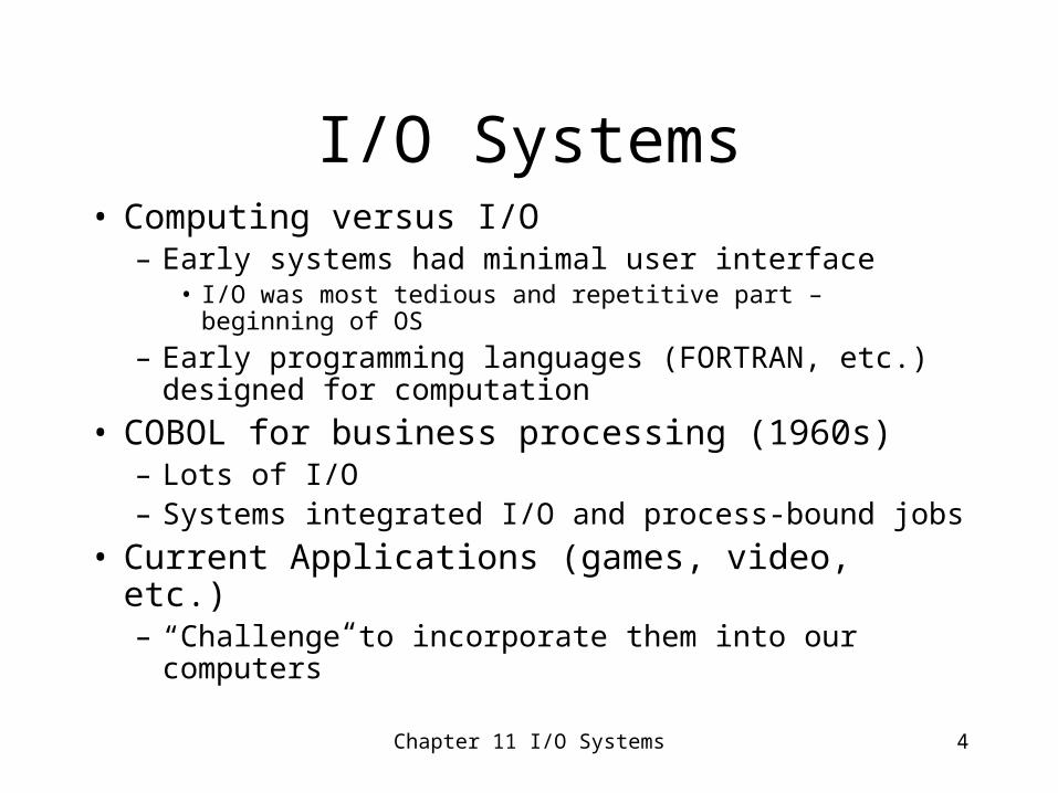
I/O Systems• Computing versus I/O
– Early systems had minimal user interface• I/O was most tedious and repetitive part – beginning of OS
– Early programming languages (FORTRAN, etc.) designed for computation
• COBOL for business processing (1960s)– Lots of I/O– Systems integrated I/O and process-bound jobs
• Current Applications (games, video, etc.)– “Challenge to incorporate them into our computers”
Chapter 11 I/O Systems 5
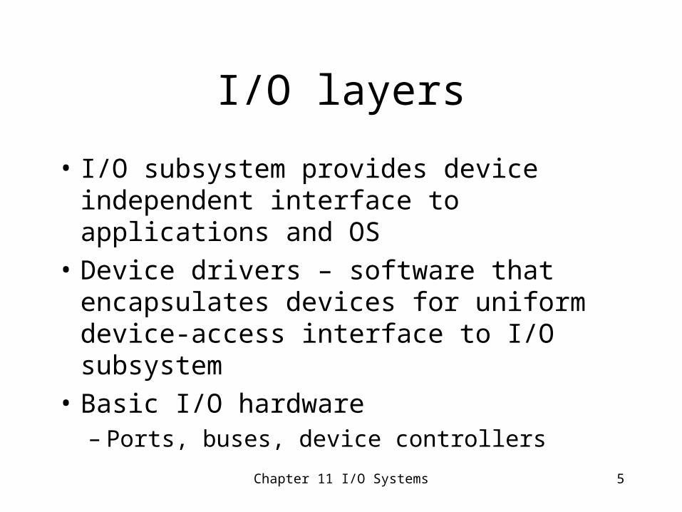
I/O layers
• I/O subsystem provides device independent interface to applications and OS
• Device drivers – software that encapsulates devices for uniform device-access interface to I/O subsystem
• Basic I/O hardware– Ports, buses, device controllers
Chapter 11 I/O Systems 6
Question
• Why are i/o functions divided into separate layers?a.To handle the increased complexity of devices
b.To provide a uniform interface for application programs and OS using so many different types of devices
ans: a and b
Chapter 11 I/O Systems 7
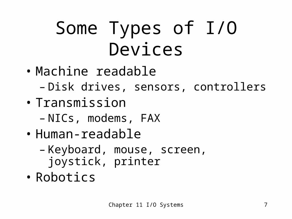
Some Types of I/O Devices
• Machine readable– Disk drives, sensors, controllers
• Transmission– NICs, modems, FAX
• Human-readable– Keyboard, mouse, screen, joystick, printer
• Robotics
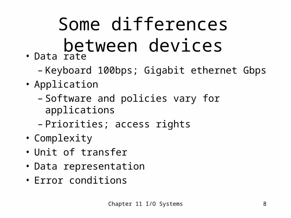
Some differences between devices• Data rate
– Keyboard 100bps; Gigabit ethernet Gbps• Application
– Software and policies vary for applications– Priorities; access rights
• Complexity• Unit of transfer• Data representation• Error conditions
Chapter 11 I/O Systems 8
Chapter 11 I/O Systems 9
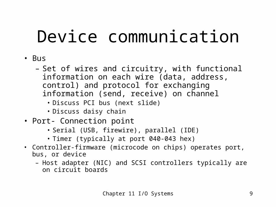
Device communication• Bus
– Set of wires and circuitry, with functional information on each wire (data, address, control) and protocol for exchanging information (send, receive) on channel
• Discuss PCI bus (next slide)• Discuss daisy chain
• Port- Connection point• Serial (USB, firewire), parallel (IDE)• Timer (typically at port 040-043 hex)
• Controller-firmware (microcode on chips) operates port, bus, or device– Host adapter (NIC) and SCSI controllers typically are on circuit
boards
Chapter 11 I/O Systems 10
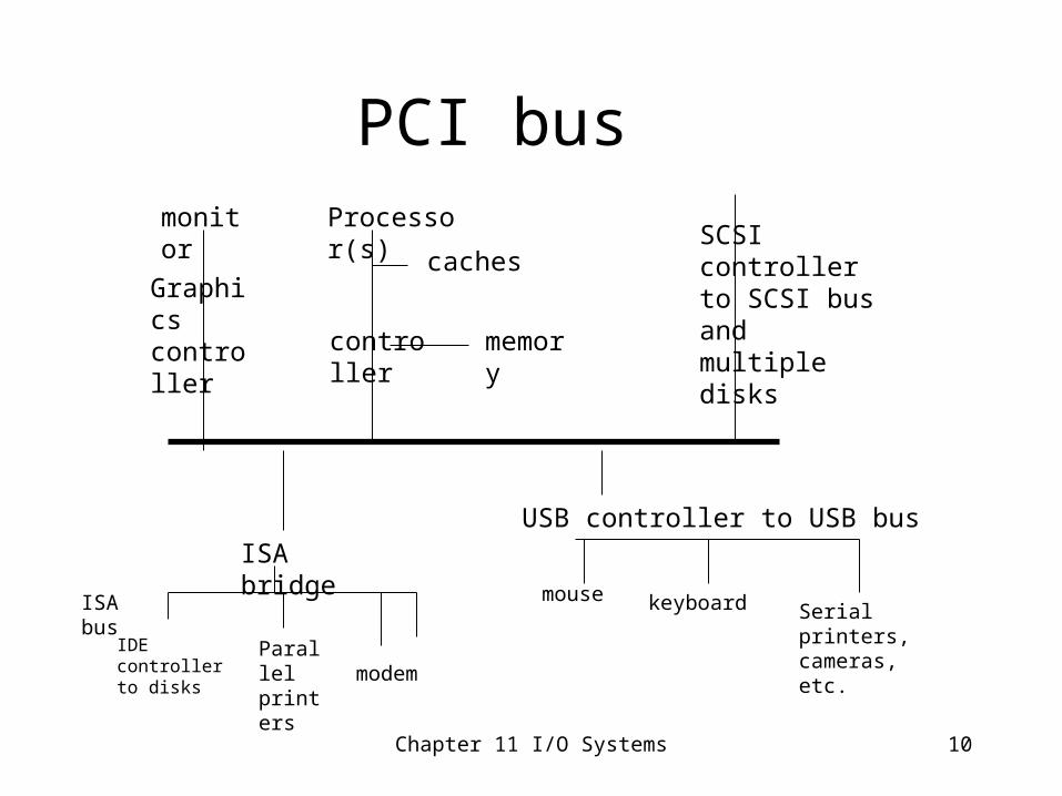
PCI bus
monitor
Graphicscontroller
Processor(s)
caches
memorycontroller
USB controller to USB bus
SCSI controller to SCSI bus and multiple disks
ISA bridge
IDE controller to disks
Parallel printers modem
ISA bus mouse keyboard Serial printers, cameras, etc.
Chapter 11 I/O Systems 11
PCI bushttp://www.tech-pro.net/intro_pci.html
• This is an edited version of an article that appeared a few years ago in PC Support Advisor. Although it provides a good general introduction to PCI bus concepts, further improvements have been made since the article was written.)
• The acronym PCI stands for Peripheral Component Interconnect, which aptly describes what it does. PCI was designed to satisfy the requirement for a standard interface for connecting peripherals to a PC, capable of sustaining the high data transfer rates needed by modern graphics controllers, storage media, network interface cards and other devices.
• Earlier bus designs were all lacking in one respect or another. The IBM PC-AT standard ISA (Industry Standard Architecture) bus, for example, can manage a data transfer rate of 8MB/sec at best. In practice, the throughput that can be sustained is much less than that. Other factors, like the 16-bit data bandwidth and 24 bit wide address bus - which restricts memory mapped peripherals to the first 16MB of memory address space - made the ISA bus seem increasingly outmoded .
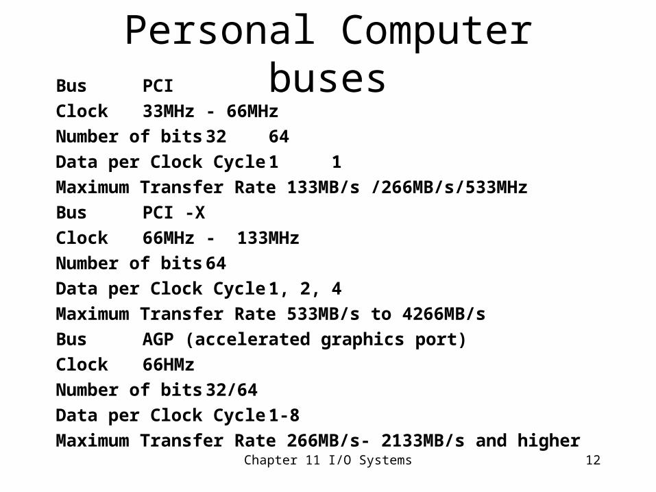
Personal Computer busesBus PCI
Clock 33MHz - 66MHz
Number of bits 32 64
Data per Clock Cycle 1 1
Maximum Transfer Rate 133MB/s /266MB/s/533MHz
Bus PCI -X
Clock 66MHz - 133MHz
Number of bits 64
Data per Clock Cycle 1, 2, 4
Maximum Transfer Rate 533MB/s to 4266MB/s
Bus AGP (accelerated graphics port)
Clock 66HMz
Number of bits 32/64
Data per Clock Cycle 1-8
Maximum Transfer Rate 266MB/s- 2133MB/s and higherChapter 11 I/O Systems 12
Chapter 11 I/O Systems 13
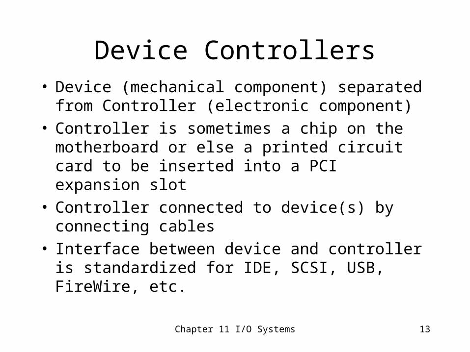
Device Controllers• Device (mechanical component) separated from
Controller (electronic component)• Controller is sometimes a chip on the motherboard
or else a printed circuit card to be inserted into a PCI expansion slot
• Controller connected to device(s) by connecting cables
• Interface between device and controller is standardized for IDE, SCSI, USB, FireWire, etc.
Chapter 11 I/O Systems 14
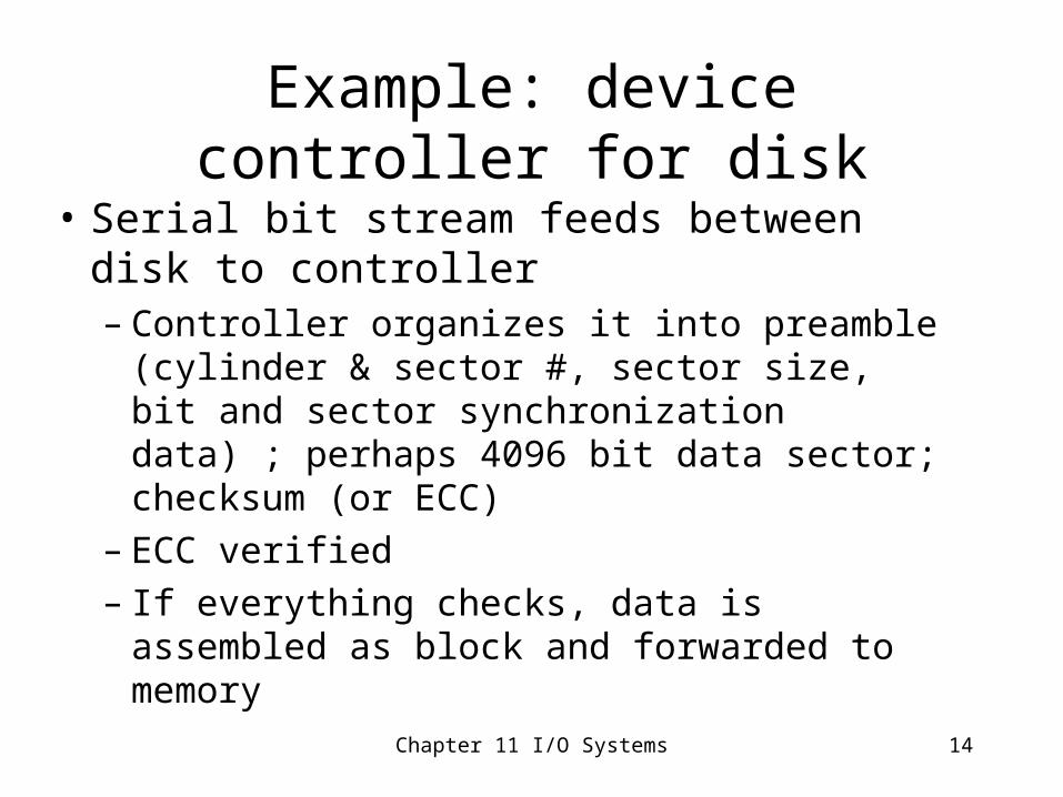
Example: device controller for disk
• Serial bit stream feeds between disk to controller– Controller organizes it into preamble (cylinder
& sector #, sector size, bit and sector synchronization data) ; perhaps 4096 bit data sector; checksum (or ECC)
– ECC verified– If everything checks, data is assembled as block
and forwarded to memory
Chapter 11 I/O Systems 15
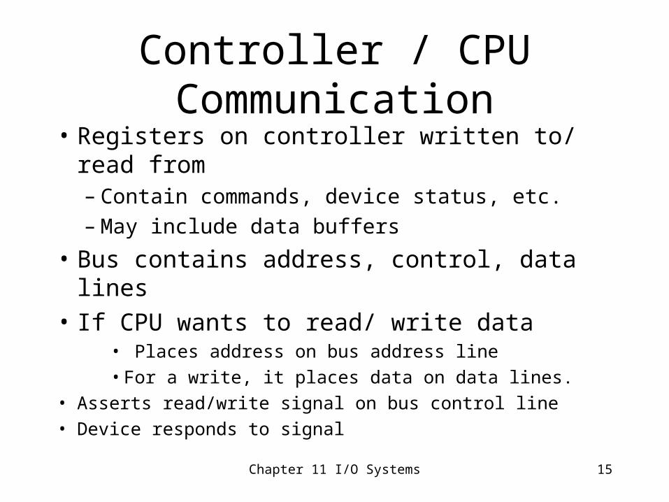
Controller / CPU Communication
• Registers on controller written to/ read from– Contain commands, device status, etc.– May include data buffers
• Bus contains address, control, data lines
• If CPU wants to read/ write data• Places address on bus address line
• For a write, it places data on data lines.
• Asserts read/write signal on bus control line
• Device responds to signal
Chapter 11 I/O Systems 16
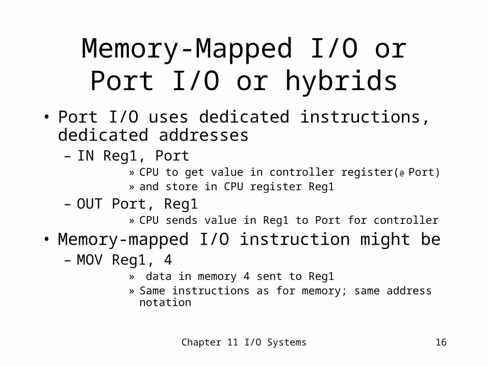
Memory-Mapped I/O or Port I/O or hybrids
• Port I/O uses dedicated instructions, dedicated addresses– IN Reg1, Port
» CPU to get value in controller register(@ Port) » and store in CPU register Reg1
– OUT Port, Reg1» CPU sends value in Reg1 to Port for controller
• Memory-mapped I/O instruction might be– MOV Reg1, 4
» data in memory 4 sent to Reg1» Same instructions as for memory; same address notation
Chapter 11 I/O Systems 17
Memory-Mapped I/O
• Each control register is assigned a unique memory address (devices and memory share memory address space); uses same instructions as CPU programs
• Programmer can use C code (Port I/O requires some assembly code to distinguish between instructions)
• Each method has some disadvantages
Chapter 11 I/O Systems 18
Controller/host handshake with interface registers
• Status register - set by controller– Completed/failure– Busy bit for availability
• Control register – set by host– Control information for speed, mode (read/write),
parity checking on/off, word length, full/half duplex– Command ready bit
• Data-in register – set by controller; read by host• Data-out register – written by host; read by controller for
output to device• Possibly input/output is cached in multiple registers
Chapter 11 I/O Systems 19
Sample Polling Protocol • Host polls for busy bit to be off (busy waiting)• If busy bit it off (device free), host can send
signals (on bus lines) to– set mode bit in command register to write– place byte(s) in data-out register (other info possible)– set command-ready bit
• Controller sets busy bit– fetches data-out from register– outputs data-out to device – sets status bit for success/ failure ` `– clears command-ready bit, busy bit
Chapter 11 I/O Systems 20
Interrupts for device I/O
• In hardware– Device sends signal (IRQ) on interrupt-request line– Interrupt controller asserts signal; identifies interrupt #– Signal causes CPU to interrupt what it is doing
• Interrupt # identifies position in interrupt vector that holds address of ISR
– CPU saves value of current PC (possibly other values)– Transfers to interrupt vector, indirectly
• Location contains (changeable) address of interrupt handler (ISR)• In software
– ISR may disable interrupts, save state of registers it needs, enable interrupts
– ISR determines nature of interrupt and handles interrupt– ISR may restore registers of interrupted process
Chapter 11 I/O Systems 21
Interrupt-controller
• Prevents interruption during critical processing
• Prioritizes interrupts• Determines which device raised interrupt• Programmable or Advanced Programmable
Interrupt-controllers– Enables different prioritization methods (hard,
rotating, cascading), for example
Chapter 11 I/O Systems 22
Question
• Why are interrupts prioritized?a. It is faster
b. It is fairer
c. It is important not to lose data that may be overwritten by fast devices
d. Prioritization prevents deadlockAnswer: c
Chapter 11 I/O Systems 23
Masking and disabling interrupts
• Maskable or nonmaskable– Nonmaskable interrupts (power or memory failure)– Maskable interrupts – devices, etc.
• PCI bus has 2 interrupt request lines– Maskable interrupt line can be temporarily turned off during
execution of critical instructions
• Interrupt chaining– Each address in interrupt vector may point to a chain of
ISRs• Nested prioritized interrupts
– Interrupts stored and handled in priority order
Chapter 11 I/O Systems 24
Precise and Imprecise Interrupts
• Pipelining of instructions - multiple instructions are in a state of execution
• When an interrupt occurs, multiple instructions may be partially executed – This is called an imprecise interrupt– System must ensure that the instructions previous to the instruction
whose PC has been saved are completed– System can roll back those instructions after the one whose PC has
been saved (possibly including PC instruction)– Adds complexity to current systems
Chapter 11 I/O Systems 25
Exceptions or traps
• Interrupt mechanism is used to handle software traps– Examples: memory access violations, division by zero
• Interrupt mechanism may be used for page or segment faults
• Interrupt mechanism may be used for calls to the kernel
• Threads may communicate thru interrupts– Place common data on system stack
Chapter 11 I/O Systems 26
DMA (Direct Memory Access)
• Fast I/O processor• Kernel process writes command block to DMA
– Address in memory, address on device, r/w, # of blocks
• DMA transfers block to/from memory to device; interrupt upon completion– Memory cycle stealing– DMA “handshake” with device controller (perhaps
IDE)
• DVMA can transfer block between two devices
Chapter 11 I/O Systems 27
Question
• DMAs use cycle stealing. What does that mean?a. CPU cycles are stolen by the DMA controllerb. Memory cycles are stolen from other devices
by the DMA controllerc. Memory cycles are stolen from the CPU by the
DMA controller• Ans: c (i.e., CPU is prevented from accessing
memory while DMA is transferring data in or out)
Chapter 11 I/O Systems 28
Kernel I/O structure
• Kernel requests uniform set of services from subsystem– (through kernel-subsystem interface)– Typically- read(), write(), seek()
• Subsystem requests services of device drivers, which encapsulate peculiarities of devices– (through subsystem- driver interface)– Example: PCI device driver
• Drivers requests services (data, error flags, etc.) of controllers– (driver- controller interface)– Example of controller: PCI bus device controller
• Controllers handle I/O devices - ever more different and complex– Speed, sharing, unit of transfer, access method, in sync or not– They all transfer bits– Example of device: PCI bus
Chapter 11 I/O Systems 29
Back door to device driver
• Bypasses subsystem– In UNIX, for example, the command ioctl ()
• Returns File descriptor– In UNIX, devices are handled as files
• Determines command to device driver – Defined integer value
• Provides pointer to data structure with control information, data for output if necessary
Chapter 11 I/O Systems 30
Clocks and Timers
• Either hardware clock or very fast (high frequency) counter is used for timing services– Generates periodic interrupts (clock ticks)
– Programmable clocks control frequency of interrupt
– Clock Driver• Maintains time of day
• May limit CPU time allowed to process
• Handles the alarm system call
• Provides software timers for the system
• Statistics, monitoring, etc.
Chapter 11 I/O Systems 31
Software Timers
– Software interrupts are attached to clock ticks• Time slice interrupt
• Preemptive priority scheduling
• Periodic write-out of cache to disk
• Network time-out and resend, break connections, etc.
• Can provide services to user programs – – /usr/bin/time (Cshell)
– sleep () in programs
Chapter 11 I/O Systems 32
Kernel I/O Subsystem services
• Management of name space for files and devices• Access control authentication for files and devices• Operation control (modem cannot do a seek)• File-system space allocation• Device allocation• Buffer, i/o caches, spooling management• I/O scheduling• Device monitoring• Error handling, failure recovery• Device-driver configuration and initialization• Scheduling of disk operations• Table Maintenance
Chapter 11 I/O Systems 33
Performance Issues -Buffers
• Buffering ameliorates speed mismatch between producer and consumer– Ex: modem and hard disk– Typically, double buffering is used
– Once buffer is filled, disk write is requested– Modem can continue; writes to other buffer until output is completed
• Ameliorates differences in data-transfer size– Perhaps holds data until it can be defragmented (reassembled)
Chapter 11 I/O Systems 34
Performance Issues - Caching
• Cache is high speed storage that holds, by definition, copy of data from slower storage– Used for efficiency purposes
• Cache on CPU is completely hardware controlled– Only issue for OS would be size, replacement
• Caches in memory, on devices
Chapter 11 I/O Systems 35
Performance issues - Spooling
• Disk buffers holding data for output (or input)– Control is handled by system daemon process or kernel
thread• Spooling list is available
– Job can be removed
– Output is delayed until complete (usually)• Can cause deadlock over printer (or other hardware) if a
process holds (locks) printer while waiting for other resource
– Output process can continue executing if printer is busy
– Consistent output as processes complete one at a time
Chapter 11 I/O Systems 36
I/O protection
• All I/O operations are privileged– User program traps to kernel, kernel suspends process,
verifies user rights, completes I/O, signals user
• Memory-mapped and i/o port locations are denied to users. Users must trap to kernel
• But graphic games need direct access to memory-mapped graphics controller memory– Performance issue – cost of trap to kernel– OS can provide a section of graphics memory to a
single user at a time using dedicated bus
Chapter 11 I/O Systems 37
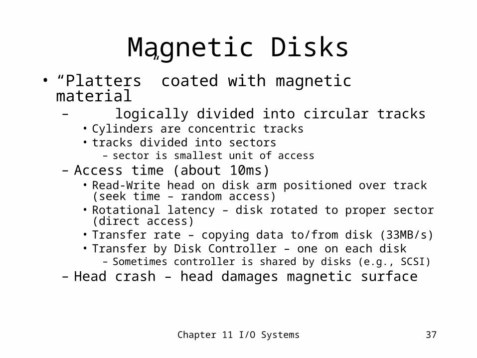
Magnetic Disks• “Platters” coated with magnetic material
– logically divided into circular tracks• Cylinders are concentric tracks• tracks divided into sectors
– sector is smallest unit of access
– Access time (about 10ms)• Read-Write head on disk arm positioned over track (seek time
– random access)• Rotational latency – disk rotated to proper sector (direct
access)• Transfer rate – copying data to/from disk (33MB/s)• Transfer by Disk Controller – one on each disk
– Sometimes controller is shared by disks (e.g., SCSI)
– Head crash – head damages magnetic surface
Chapter 11 I/O Systems 38
Magnetic Tape
• Audio and video recording; archival data storage (disks have taken many of these functions)
• Sequential access– “direct” access is achieved by fast wind, rewind
• Capacity– 2010 - the highest capacity Hitachi tape cartridges
stored up to 50 TB of data without compression
Chapter 11 I/O Systems 39
Optical Disks• Cheaper
• R or R/W
• Capacity – 30GB and more
• Slower than hard disks (at least currently)
• Have replaced floppy disks– Capacity is greater– Cost per byte is less– Reliability is probably better as well
Chapter 11 I/O Systems 40
Disk Structure
• Sectors, blocks, clusters– A sector is the minimal unit of allocation (hardware determination)– A block is a minimal unit of transfer
• OS determines the number of sectors to a block
– Blocks (logical) are mapped onto sectors• Mapping difficulties
– Number of sectors may decrease for inner cylinders– Bad sectors are mapped onto other positions holding “spare” sectors
– In Windows, a cluster is the minimal unit of file allocation• OS determines the number of blocks in cluster to increase contiguity
in file storage
Chapter 11 I/O Systems 41
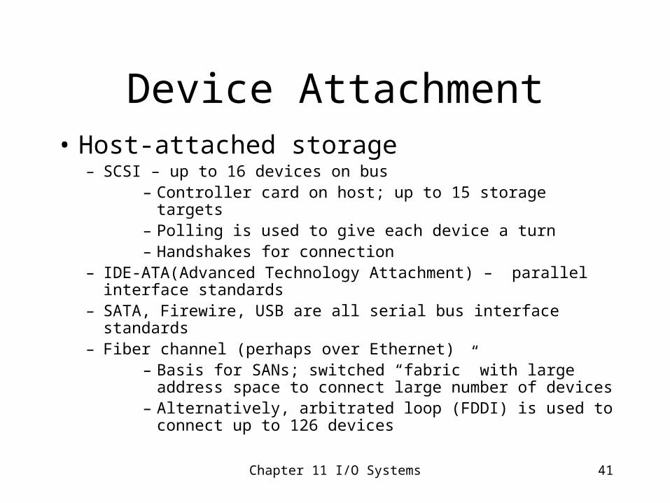
Device Attachment• Host-attached storage
– SCSI – up to 16 devices on bus– Controller card on host; up to 15 storage targets– Polling is used to give each device a turn– Handshakes for connection
– IDE-ATA(Advanced Technology Attachment) – parallel interface standards
– SATA, Firewire, USB are all serial bus interface standards– Fiber channel (perhaps over Ethernet)
– Basis for SANs; switched “fabric” with large address space to connect large number of devices
– Alternatively, arbitrated loop (FDDI) is used to connect up to 126 devices
Chapter 11 I/O Systems 42
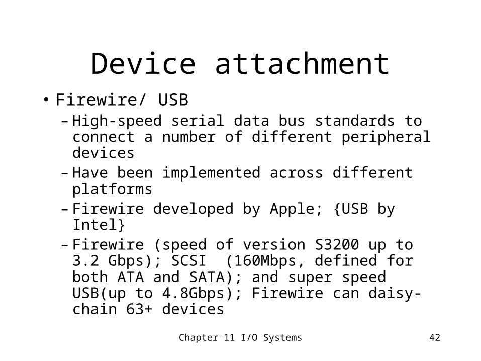
Device attachment• Firewire/ USB
– High-speed serial data bus standards to connect a number of different peripheral devices
– Have been implemented across different platforms
– Firewire developed by Apple; {USB by Intel} – Firewire (speed of version S3200 up to 3.2
Gbps); SCSI (160Mbps, defined for both ATA and SATA); and super speed USB(up to 4.8Gbps); Firewire can daisy-chain 63+ devices
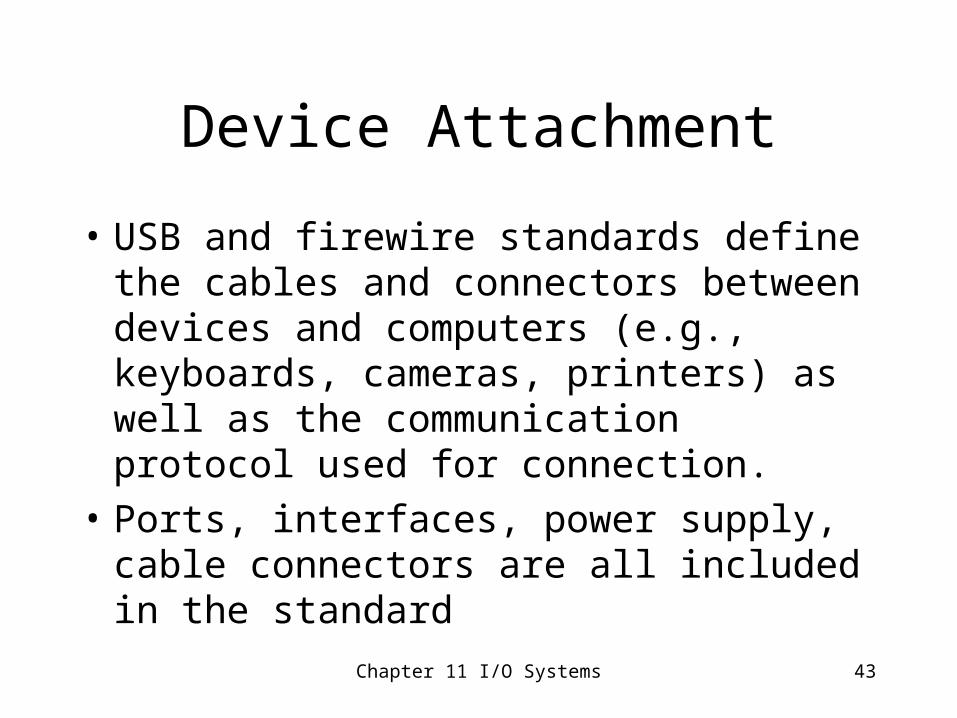
Device Attachment
• USB and firewire standards define the cables and connectors between devices and computers (e.g., keyboards, cameras, printers) as well as the communication protocol used for connection.
• Ports, interfaces, power supply, cable connectors are all included in the standard
Chapter 11 I/O Systems 43
Chapter 11 I/O Systems 44
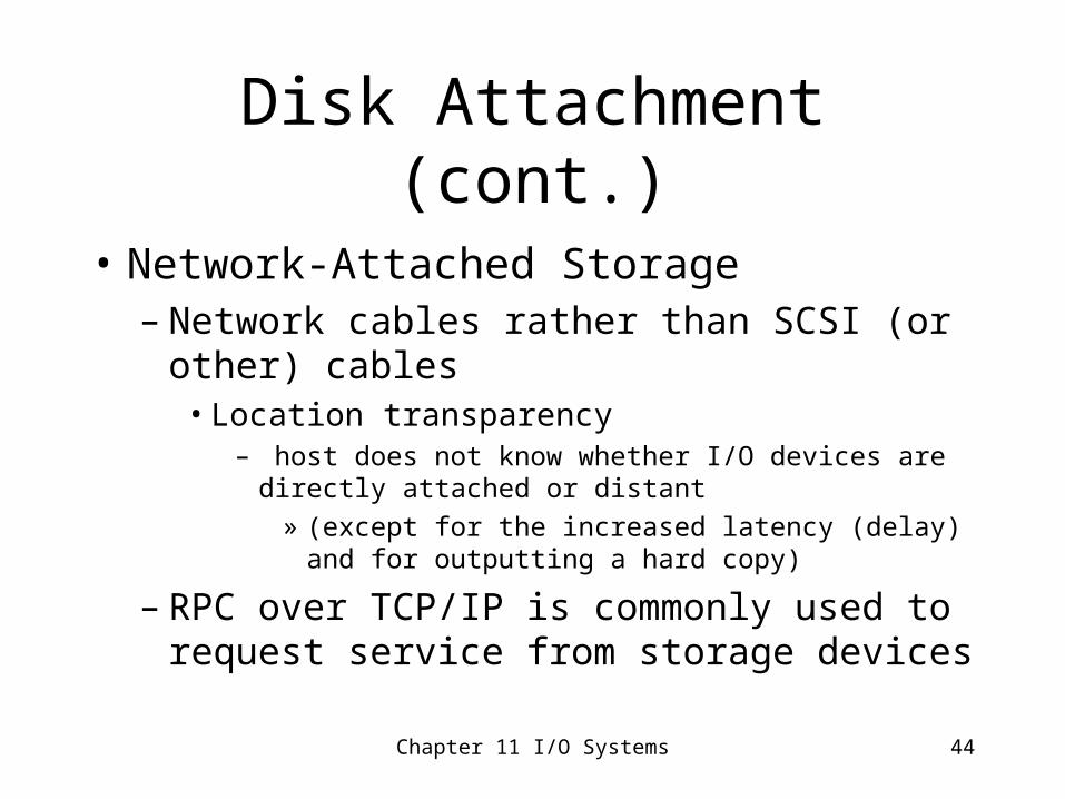
Disk Attachment (cont.)
• Network-Attached Storage– Network cables rather than SCSI (or other)
cables• Location transparency
– host does not know whether I/O devices are directly attached or distant
» (except for the increased latency (delay) and for outputting a hard copy)
– RPC over TCP/IP is commonly used to request service from storage devices
Chapter 11 I/O Systems 45
Disk scheduling
• Assume that we have a large number of requests for disk i/o– Scheduling these requests in specific orders can
increase throughput and decrease average waiting time
– Issues and algorithms are similar to process scheduling although here we try to minimize hardware issues such as seek time (time for disk arm to move the head to the required cylinder).
Chapter 11 I/O Systems 46
Disk Management• Disk formatting
– Disk must be formatted before it is used– Low level formatting – usually when
manufactured• Divides magnetic recording units into sectors
– Each sector contains a header, a trailer (control info for controller) and a data area (usually 512-1024 bytes)
» Sector number, error-correcting code» Soft error if ECC can recover from mismatch
• Bad sectors are isolated• Spare sectors are set aside for later needs
Chapter 11 I/O Systems 47
OS disk formatting
• High Level formatting– OS installs multi-level data structures on a disk– Partitions disk into sets of cylinders
• Logical disks are mapped onto the physical disk• Can provide a separate logical disk for OS code with limited
access rights for users• Separate user data to make backups easier
– Logical formatting• Create disk’s file system• Maps of free and allocated space, initial directory of files on disk
Chapter 11 I/O Systems 48
Raw Disks• OS activity is limited for raw disks (except
for combining sectors into blocks)– Swap disks
• Process data may be stored contiguously• Eliminate cost of i-node directories, linking blocks,
etc.
– Database systems• Provide their own high level formatting
– These services bypass buffer cache, file locking, prefetching, directories, file naming
Chapter 11 I/O Systems 49
Boot block• Bootstrap program on system disk in static
location– Minimal boot program in ROM executed when
machine is powered on• Brings rest of bootstrap program from disk into
memory and transfers to it– Bootstrap program stored in “boot blocks” at fixed
location on (boot or system) disks
– Program does system and register initialization
– Copies OS kernel from disk into memory
– Transfers control to (jumps to) some address in memory to begin executing kernel
Chapter 11 I/O Systems 50
Swap Space Management
• Swap space is an extension of memory– Disk access is much slower than memory
access• Access to swap space should be minimized for
required virtual memory performance• Swap space was typically much larger than main
memory until the large increases of main memory today
– Swap space may be used for entire process or only for swapping out pages when necessary
Chapter 11 I/O Systems 51
Swap-space location• Part of normal file system
– Same file-handling routines used as other services• Inefficient, particularly the traversing of file-system data
structures
• Raw partition or separate disk– Algorithms focus on speed rather than storage
efficiency
• Linux, Windows may allow raw partitions to be incremented, if necessary, with space in the normal file system
Chapter 11 I/O Systems 52
RAID (redundant arrays of I disks)
• I (inexpensive, independent)• Performance and reliability issues by
accessing disks in parallel– Reliability
• Assume mean time to failure of a single disk is 100,000 hours
– If we have 100 disks in our organization, the mean time for one disk to fail is 1000 hours or 42 days!
» Necessity of some type of backup» If we want no loss of data at all, then we need parallel
redundant disk updates
Chapter 11 I/O Systems 53
RAID -redundancy• Mirroring
– Two disks, one controller. Every write is to both disks
• Issues – Single controller can fail (you can duplex instead with
different controllers)
– If disks are both old and/or from same manufacturer, probability of both failing is considerably higher
– Power failures must also be handled
» If power fails in between the two disk writes, which update is correct?
Chapter 11 I/O Systems 54
Performance improvement with RAID
• Striping – Bit-level striping
• Say bit i is read/written to disk i
• We can decrease the time necessary to fetch a block by a factor based on the number of disks.
– Block level striping• Each successive block is stored in “next” disk
– Byte level striping is also possible
Chapter 11 I/O Systems 55
RAID levels
• Schemes to balance reliability, efficiency, and cost– RAID level 0 – block striping for efficiency– RAID level 1 – disk mirroring for redundancy (possibly multiple
paths for reads for efficiency) 100% overhead for writes; double # of disks
– RAID level 2 – ECC organization with bit striping for reliability and efficiency
– 2-3 error correcting bits stored on extra disk(s) for each byte– 3 extra disks must be added for 8 disks– Note that error correcting disks must be updated for each write to a data
disk– RAID level 3 – byte-interleaved parity organization
• Byte striping, with parity bytes (checksum) on separate disk– Controller will be able to tell which disk was damaged – Parity disk must be updated during each write
Chapter 11 I/O Systems 56
RAID levels
• RAID level 4 – block-interleaved parity organization– Block-level striping; parity block on an extra
disk to be used for reconstruction of failed block
• Multiple reads can be done concurrently, but writes must all wait for parity block
• Scalable, since new disk can be initialized to all 0s and parity block is still correct
Chapter 11 I/O Systems 57
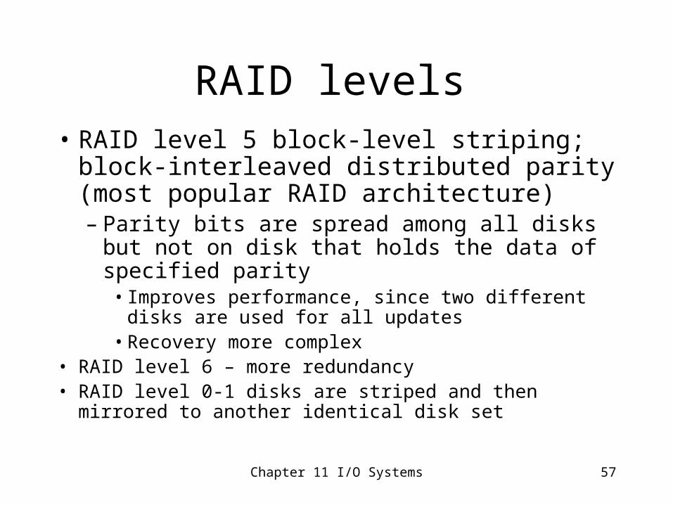
RAID levels • RAID level 5 block-level striping; block-
interleaved distributed parity (most popular RAID architecture)– Parity bits are spread among all disks but not on
disk that holds the data of specified parity• Improves performance, since two different disks are
used for all updates• Recovery more complex
• RAID level 6 – more redundancy • RAID level 0-1 disks are striped and then mirrored to
another identical disk set
Chapter 11 I/O Systems 58
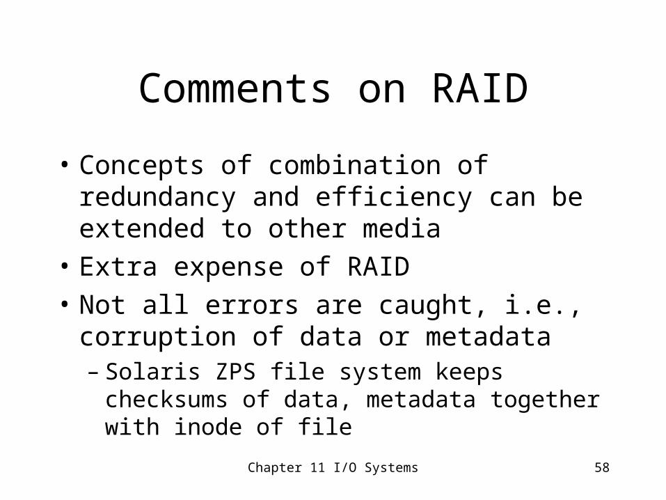
Comments on RAID
• Concepts of combination of redundancy and efficiency can be extended to other media
• Extra expense of RAID
• Not all errors are caught, i.e., corruption of data or metadata– Solaris ZPS file system keeps checksums of
data, metadata together with inode of file
Chapter 11 I/O Systems 59
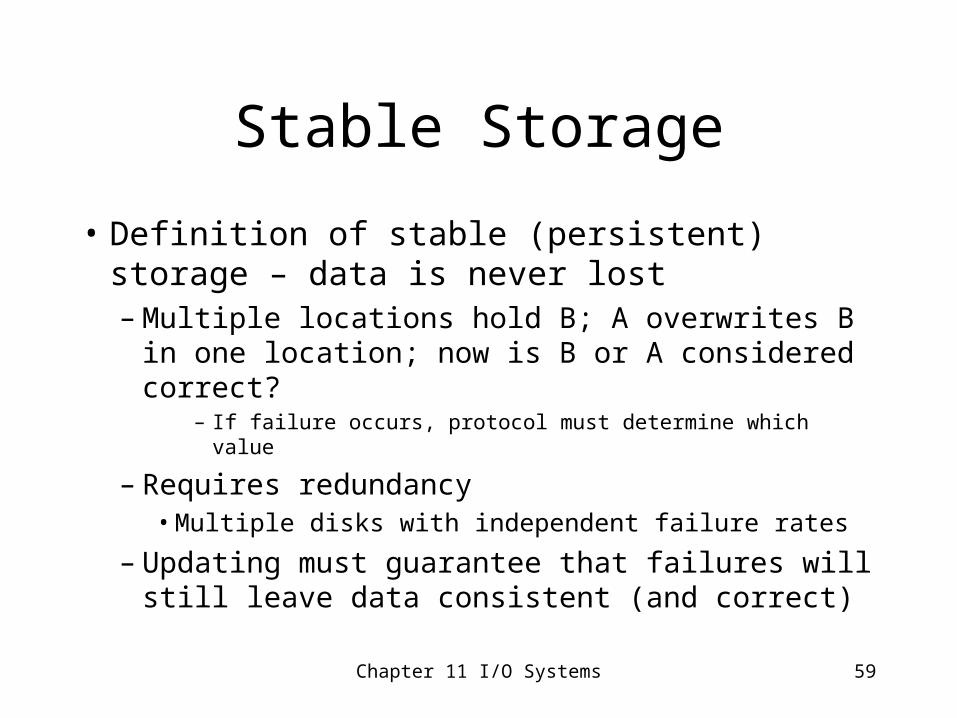
Stable Storage
• Definition of stable (persistent) storage – data is never lost – Multiple locations hold B; A overwrites B in
one location; now is B or A considered correct?– If failure occurs, protocol must determine which value
– Requires redundancy• Multiple disks with independent failure rates
– Updating must guarantee that failures will still leave data consistent (and correct)
Chapter 11 I/O Systems 60
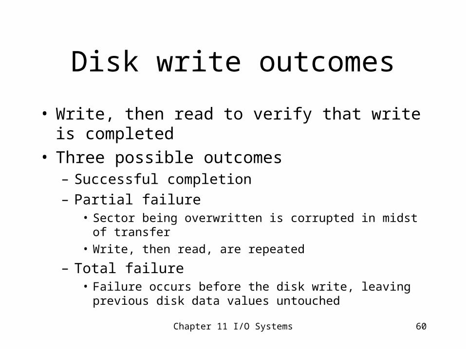
Disk write outcomes
• Write, then read to verify that write is completed• Three possible outcomes
– Successful completion
– Partial failure• Sector being overwritten is corrupted in midst of transfer
• Write, then read, are repeated
– Total failure• Failure occurs before the disk write, leaving previous disk data
values untouched
Chapter 11 I/O Systems 61
Assume any type of failure occurs
• Controller can sense this and sends error message– If both disks hold same data, we assume they were not
corrupted
– If one block/ disk can be detected as incorrect, replace it with data from the other
– If contents are not the same, but both disks appear correct, copy the data from the second disk into the first
• Or assume that update to second disk was not complete, and we return to earlier state of no change
• Update can be stored in a NVRAM and repeated
Chapter 11 I/O Systems 62
Robotic jukebox
• Automated hierarchical storage for removal media– May hold tens of drives and thousands of
cartridges or disks– Retrieval is typically tens of seconds or minutes– Common for archival storage and infrequently
used information• Brought to secondary storage when needed
Chapter 11 I/O Systems 63
Optical JukeboxOptical Jukebox - An automated storage device that holds many optical disks with a small number of
optical read/write drives used to archive and store massive amounts of data. A robotic arm moves optical disks from storage slots to the drives. Also referred to as an optical library.
• Phase-Change – A recording process that uses laser light to convert points on an optical disk from an amorphous state to a crystalline state.
• Picker – The robotic component of an optical jukebox that moves optical disks to and from storage slots and optical drives. Also referred to as a media picker.
• Shelf – See Slot.• Single-Head Drives – Drives that can only read or write to one media surface at a time. The disk must
be flipped and re-inserted into the drive in order to read or write to the other side. 5 ¼” drives are single-headed.
• Slot – An area inside an optical jukebox where optical disks are stored. A jukebox can store as few as 20 optical disks or as many as 638, depending on the manufacturer and model number of the jukebox.
• Time to Deliver Data (TDD) – The total time it takes to deliver requested data back to an application. This includes the time it takes for the picker to fetch an optical disk, move it to and insert it into an optical drive, spin up the drive, locate the requested data, and transfer it back to the application. Measured in seconds.
• WORM – Write Once Read Many. A type of optical media that allows data to be written only once. Files cannot be overwritten. Commonly used in regulated industries requiring permanent file archives. Some regulatory agencies include the Securities Exchange Commission, Nuclear Regulatory Commission, and Food and Drug Administration.
• http://www.9to5computer.com/OPTICAL-JUKEBOX-TERMS.htm
Chapter 11 I/O Systems 64
Future mass-storage media
• Holographic storage– Laser to record 3-dimensional arrays of pixels– Very fast
• Microelectronic mechanical systems
• Biological mechanisms
Chapter 11 I/O Systems 65
Question
• Name three protocol standards for connecting devices to hosts.– SCSI – firewire – USB – LANs– SANs
Chapter 11 I/O Systems 66
What is a jukebox?
• Something that holds records.
• What is a robotic jukebox?
Chapter 11 I/O Systems 67
Power Management
• Most computers consume about 200-watts (200 joules per second) – that is a lot of energy for a company’s computers
• Battery-powered computers hold their charge for at most a few hours
• Wireless systems use even more power when continually sending/ receiving data
• Minimal improvements in battery life
Chapter 11 I/O Systems 68
Operating systems can save power
• Devices can be made to sleep/ hibernate• Displays (big users of power) can be lit in
zones• Disks (big users of power) powered down
when not in use; applications programs delay writing out to disk; RAM disk used
• OS uses artificial intelligence to estimate sleep times, etc.


![Chapter_01[Crude Oil Treating Systems1]](https://img.pdfslide.net/doc/110x75/5436c3e2219acd57088b4615/chapter01crude-oil-treating-systems1.jpg)