Embed Size (px)
Citation preview

FAIRFAX COUNTY PUBLIC FACILITIES MANUAL
8.
6.
4.
3.
2.
1.0
0.8
w 0.6W
CJ
0.4QW
w 0.3WHC
0.2t-H
HHo<u53O 0.1 7
.08
.06
.04
.03Capacity is total sediment basin volumeup to emergency spillway crest.
.02Conversion Values
1 Ac Ft = 43,560 ft3 = 1,613 CY1 Ac In = 3,630 ft3 = 134.4 CY
.0110 20 30 40 50 60 70
TRAP EFFICIENCY - %80 90 100
Ref. Sec. 11-0105.6.11-0106.2 11 0109.7.11 0110.3
PLATE NO. STD. NO.MAXIMUM PROBABLETRAP EFFICIENCY
OF SEDIMENT BASINS 1-11Rev. 1-00, 2011 Reprint*2018 Reprint
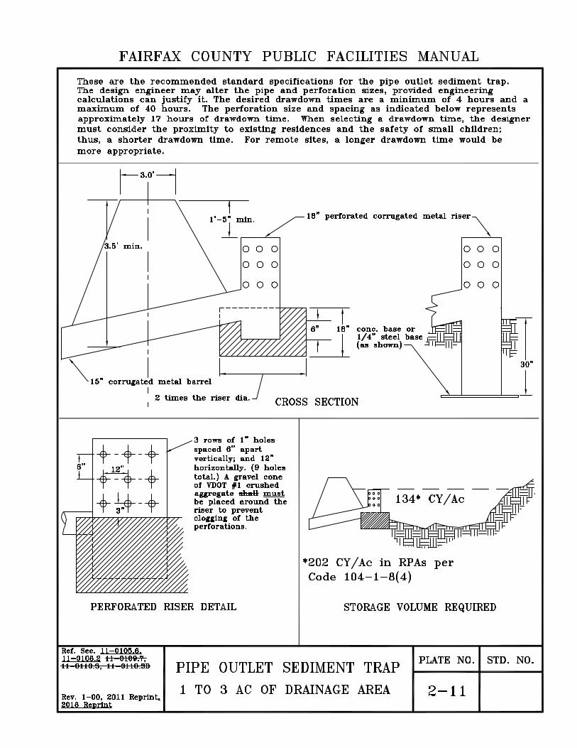
FAIRFAX COUNTY PUBLIC FACILITIES MANUALThese are the recommended standard specifications for the pipe outlet sediment trap.The design engineer may alter the pipe and perforation sizes, provided engineeringcalculations can justify it. The desired drawdown times are a minimum of 4 hours and amaximum of 40 hours. The perforation size and spacing as indicated below representsapproximately 17 hours of drawdown time. When selecting a drawdown time, the designermust consider the proximity to existing residences and the safety of small children;thus, a shorter drawdown time. For remote sites, a longer drawdown time would bemore appropriate.
3.0*
l 18” perforated corrugated metal riser< * r > > •1 -5 mm.i
3.5* min. o o o o o oo o o o o o
I o o o o o o
18” cone, base or . u=1/4” steel base JJ(as shown) 11—6”
30”
15” corrugated metal barrel
2 times the riser dia. CROSS SECTIONi
3 rows of 1” holesspaced 6” apartvertically; and 12”horizontally. (9 holestotal.) A gravel coneof VDOT #1 crushedaggregate shall mustbe placed around theriser to preventclogging of theperforations.
63 3-6” 12”
O- - - 3- - -eo o oo o o 134* CY/Ace e o o o
-' I
*202 CY/Ac in RPAs perCode 104-1-8(4)
PERFORATED RISER DETAIL STORAGE VOLUME REQUIRED
Ref. Sec. 11-0105.6.11-0106.2 11-0109.7,11 0110.3, 11-0110.3D PLATE NO . STD. NO.PIPE OUTLET SEDIMENT TRAP
1 TO 3 AC OF DRAINAGE AREA 2-11Rev. 1-00, 2011 Reprint*2018 Reprint

FAIRFAX COUNTY PUBLIC FACILITIES MANUAL
FAIRFAX COUNTY PUBLIC FACILITIES MANUAL
-SOIL NUMBER ~ GLENELG SILT LOAM 39B-SLOPE-2 TO 7 PERCENT.SLOPE0-2 PERCENT.2-7 PERCENT7-15 PERCENT.15-25 PERCENT.25-45 PERCENT.
.39B - B
ABC1)E
Soil LinesSoil survey maps are to be used for general planningpurposes only. Please be aware that soil lines are notdefinitve. Soils gradually phase into one another andcharacteristics of neighboring soil types will be foundwithin a soil's borders
Marumsco SoilsMafcumsco soils arc mapped in complexes with Other soilt > pe\ The complexes are highly variable and consist ofcombinations of clays, silts, sands and gravels. I hc> mayalso be problematic. In steep areas that contain clays knovyas "marine oLtys." slope stability can be a problem. In /addition, structures constructed on clays found in this/complex could suffer foundation distress ifadequat^precautions are noVuaken during design and oonstnKtion.
Pi^viously MappedMarine Cray
These areas were mapped as marinesoil surveys. Marine clays are hijgy hrink-swell soils thatcan cause foundation distress. T
lys in previous
are sometimesrelered to as Potomac C lays or^eltaV Clav s.
Non-Marine ClayHigh ShrinR\SwellSoils
Soils contamin^dther shrink ing-swel ling claysthat can lead t/foundation distress if precautionsare not takorduring design and construction
Potential AsbestosContaining Soils
/these soils are mapped over naturally asbestos-containing bedrock. Safety precautions must be takenduring construction. Orange soils, which overlie a majorityof this geology, also contain shrinking-swelling clays whichcan cause foundation distress.
© QuarryLandfill
PLATE NO STi} NORef. Set/ 11-0408.11
SYMBOLS SHOWN ON SOILMAPS OF FAIRFAX COUNTY 4-11
;ev. 6— 11

FAIRFAX COUNTY PUBLIC FACILITIES MANUALSurface accumulation of organic materials undergoing varying stages of plant decomposition.Horizons designated 01 contain loose leaves and other recognizable vegetative matter. Horizonsdesignated 02 contain matted and decomposed organic material. The 01 and 02 layers areoften thin or insignificant because of past cultivation or construction practices.
OCO A 1 The A horizons collectively represent the surface soils that have been exposed to the most
active physical and chemical weathering processes, resulting in leaching or downward movementof dissolved minerals and fine clay particles into lower horizons. Many of the soily weatherableminerals have leached out of the entire soil system and into the groundwater and streams. A1horizons are enriched with finely divided organic matter and are the "topsoil” materials thatoccur naturally in place. Organic matter content of naturally occurring A1 horizons in theCounty seldom exceeds 1.5 % by weight and is usually less than 1.0 %.The A2 horizons are the most severely leached or stripped layers. The A3 horizon is gradation-al to underlying strata. Past cultivation and construction practices have frequently mixed the0 and A horizons into a combined surface soil layer with no distinct subhorizon. The "topsoil”that is sold commercially is usually this mixed layer material. The 0 and A horizons may beentirely missing in areas that are severely eroded or disturbed by construction practices.Permeability is usually moderate to high.
LU :A2=o A< z1 \ .x
Z) -A3-00
The B horizons of the County soil are usually clay enriched as a result of (1) weathering inplace, (2) clay translocation from overlying layers, or (3) as a primary clay deposit. Residualsoils have developed in-situ from weathered rock and are the predominent type in the PiedmontUpland and Piedmont Triassic Lowland physiographic provinces of the County. The clay contentand clay type of the B horizon is dependent on the bedrock characteristics, subsurface soildrainage and landscaped position. Permeability is moderately slow to very slow in most B horiz-ons.The B horizon clays that have developed from micaceous schists have clays of low activity,whereas B horizons developed from diabase or other mafic rocks have highly plastic clays. The Bhorizons generally range in thickness from 2— 5’ and are often the building foundation and roadsubgrade materials of concern to developers and contractors. B horizons of the various soils havespecific characteristics with regard to structure or fabric, grain size distribution, and soil indexproperties.The B horizons in most of the residual soils have thoroughly altered the orginal structure andand the physical and chemical characteristics of the parent bedrock. B horizons of soils in theunconsolidated sediments of the Coastal Plain more closely resemble the structure and texture oftheir original parent materials than do their counterparts in the Piedmont provinces to the west.The B horizons generally contain subhorizons such as B1, B2, B3 or others. The B1 and B3 hori-zons are gradational to overlying and underlying layers. The B2 horizon is the zone of maxclay accumulation, and max secondary micro and macro structural development. Hard ce-mented Bx fragipan layers, that severely restrict permeability occur in some County soils.
2O BcnmCO
3
x > The C horizons of the County soils represent unconsolidated strata that are less intensively weath-ered than the overlying horizons. The C horizons in the residual soils of the County have weath-ered in— situ from bedrock and are often referred to as saprolite. The density of the C horizonsusually increases the degree of weathering and decreases with depth. The C horizons in residualsoils have soil properties indicative of weathering, yet retain the original mineral orientation, jointsystem and cleavage patterns of the original bedrock mass. Downward clay translocation fromoverlying horizons can often be detected in relict joints, fissures and fault zones of the saprolite.These micro and macro structural features of the C horizons are a function of bedrock type andand past geologic stresses, which often reduce the stability of soils in trench excavations andtunneling operations. Permeability varies from slow to rapid depending on rock type.The C horizons of soils in the Coastal Plain Physiographic Province are interlayered alluvial depo-sits of gravel, sand, silt and clay that often extend to depths greater than several hundred feetbefore saprolite or bedrock is encountered. The surface and subsoils may have markedly differentengineering characteristics than underlying strata. The density of soil materials generally increaseswith depth. An exception to the rule is the soft, more recent alluvial sediments and burnedorganic beds in some stream valleys. Active geologic erosion cycles have maintained the substratalayers near the surface in many steep areas resulting in insignificant development of A and B hor-izons.Fracture patterns of varying complexity often occur in the substrata and subsoil layers in theCoastal Plain. Those in the subsoil are due to near-surface physical, chemical and biological phe-nomena; those at greater depths due to soil gradation and past geologic stresses.
>>XLdO4
C<<IX{/ )
m35 M The R horizon consists of partially weathered to unweathered bedrock. The depth to bedrock and
w the bedrock characteristics depend on the geologic origin and landscape position. Bedrock depth is" generally shallow in the sedimentary, igneous and metamorphic rock of the Piedmont Triassic Low-
lands; hard bedrock requiring ripping or blasting is typically at 3 to 6’.D The depth to hard bedrock is more variable in the Piedmont Upland, ranging from 2— 5’ overlx some igneous and metamorphic rocks to 4— 100’ within areas of the metamorphic micaceous
schists of phyllites. The depth to bedrock within the Coastal Plain is similar to the Piedmont Upland. where the 2 provinces coalesce, generally along Shirley Highway (Rte. I-95 and I-395). The depth in-V creases to over 500’ along the Potomac River. The individual bedrock types have characteristic
^mineral size and orientation, joint patterns and cleavage systems.
if )
Depth range shown is schematic only. All horizons will not necessarily occur within a specific soilSeries or be proportionate to this drawing. Actual subsurface conditions depend on the soil, geo-logic conditions, and disturbance by cultivation and construction practices. Depth to bedrock maybe several hundred feet in the Coastal Plain Physiographic Province.6
Ref. Sec. 11-0106.211-0408 PLATE NO. STD. NO.
GENERALIZED STRATIGRAPHICPROFILE OF COUNTY SOILS 53-11
Rev. 1-00, 2011 Reprint*2018 Reprint

FAIRFAX COUNTY PUBLIC FACILITIES MANUAL

FAIRFAX COUNTY PUBLIC FACILITIES MANUAL
2.5” DIA.METAL FENCE POSTS
CHAIN LINK FENCEFILTER FABRICCHAIN LINK FENCE WITH ONE
LAYER OF FILTER FABRIC ATTACHED TO IT
10’ MAX.<L TO ftm
3.'V‘i'
MiiHiiili
I 42”X 36”39”
42”
UNDISTURBEDGROUNDi > FLOW=1 i3”
rH\rrt=rrt=T EMBED FILTER
FABRIC 3”INTO GROUND
i
% GROUND
CTFP-I1-30”ELEVATION VIEW
LAY FILTER FABRICIN BOTTOM OF 3”WIDE TRENCH
SSF) X X X X XSECTION VIEW
SUPER SILT FENCENO SCALE
FENCINGChain link fence shall must be 39” above grade with 3”embedded for a total fabric width of 42” . The post shall must be42” above grade with 30” placed below grade (without concrete)for a total length of 72” .
NOTESi. Chain link fence shall must be fastened securely to fence posts with
wire ties.Filter fabric shall must be fastened securely to chain link fence withties spaced horizontally 24” at the top and midsection.Physical properties of the filter fabric shall must conform to thelatest edition of THE VIRGINIA EROSION Sc SEDIMENT CONTROL HANDBOOK.When two sections of filter fabric adjoin each other, they shall mustbe overlapped by 6” .Maintenance shall must be performed as needed and material shallmust be removed when sediment build-up reaches 50% of the heightof the super silt fence.
2.3.4.5.
Ref. Sec. 11-0106.2.11— 0106.2A -1-1 OH-OTQT11 0110.3J
PLATE NO. STD. NO.SUPER SILT FENCE
NO SCALEY5-11Rev. 1-00, 2011 Reprint*2018 Reprint