Embed Size (px)
Citation preview

Qureeb Olasunkanmi Hameed
CONTROL OF A SAFETY-INSTRU-MENTED MECHATRONIC PRODUCTION SYSTEM BY DEPLOYING INTELLIGENT REMOTE TERMINAL UNITS
Master of Science Thesis
Faculty of Engineering and Natural sciences July 2020

1
ABSTRACT
Qureeb Olasunkanmi Hameed: CONTROL OF A SAFETY-INSTRUMENTED MECHA-
TRONIC PRODUCTION SYSTEM BY DEPLOYING INTELLIGENT REMOTE TERMINAL
UNITS
Master’s thesis
Tampere University
Examiners: Prof. Jose Luis Martinez Lastra and Luis Enrique Gonzalez Moctezuma
Factory Automation and Industrial Informatics
July 2020
From parallel wiring to serial fieldbus systems and now to industrial ethernet, industrial
communication protocols have evolved to meet the demands of modern industrial appli-
cations to convey not just process data but also device diagnostics and safety infor-
mation via the same physical link. Such advanced capabilities of networking solutions
are responsible for the array of intelligent devices that have become the mainstay of
modern production systems.
The theoretical part of this thesis addresses three fundamental areas of interest, in the
following order: the first part establishes the PLC as the device at the heart of a modern
industrial control system, and discusses safety PLCs as naturally evolving from the in-
creased reliability of modern microprocessor-based electronic devices; the second part
focuses on modern industrial networking technology, which have made it possible for an
industrial control system to be composed of controllers and RTUs often in multiple hier-
archies and in well-established communication relationships; and the third part is about
the protection of humans and machinery from hazards by way of design and by applying
the recommendations of relevant international standards.
The practical part implements centralized control of a profinet network of F-PLCs in a
two-level controller-RTU system with a decentralized safety architecture. Typical consid-
erations and justifications for the choice of control architecture are presented as well.
The safety system uses signals from two laser scanners to put the production system in
a safe state when the beam is broken by a foreign object.
Keywords: PLC, RTU, IEC-61131, OSI model, fieldbus, industrial ethernet, profinet,
functional safety. The originality of this thesis has been checked using the Turnitin OriginalityCheck service.

2

3
PREFACE
My profound gratitude especially goes to the Republic of Finland for the opportunity of a world-class education in a decent country. I am finally at the cusp of actualizing a dream I have nursed throughout the decade all thanks to this country. This thesis was written during an exceptional period in world history that no one has the full words to describe yet. While the number of infections from covid-19 continues to grow worldwide, a few countries, including Finland, are starting to transition to normal life which has hitherto been disrupted by the raging pandemic and which has also affected the execution of the implementation part of this thesis in no small measure: universities and several workplaces had to be shut to ensure social distancing measures aimed at stemming the spread of a disease the world is yet to fully understand. The major heroes of this moment in history are the health workers who are on the frontline of treating covid-19 patients and those national leaders who consider saving humanity ahead of the econ-omy. While there may be a surfeit of knowledge on how to rejuvenate broken economies, there is not yet hope that we will be able to bring back lives that are lost. This preface is also my letter of condolence to all those who have lost a loved one to the vicious infection that the whole world is grappling with at the moment.
Tampere, 17 July 2020
Qureeb Olasunkanmi Hameed

4
CONTENTS 1. INTRODUCTION .................................................................................................. 8
1.1 Thesis Motivation ................................................................................. 8
1.2 Objective .............................................................................................. 9
1.3 Thesis Outline .................................................................................... 10
2. LITERATURE REVIEW ....................................................................................... 11
2.1 Mechatronic Systems in Factory Automation ..................................... 11
2.2 Automation System Hierarchy: The Automation Pyramid ................... 12
2.3 Programmable Logic Controllers ........................................................ 13
2.3.1 The IEC-61131 Standard ............................................................ 15 2.3.2 Safety PLCs and Fault-tolerant PLCs .......................................... 15
2.4 Requirements of an Industrial Control Network .................................. 17
2.4.1 The ISO/OSI Reference Model ................................................... 21 2.5 PLCs as Remote Terminal Units ........................................................ 23
2.6 The Fieldbus Standard ....................................................................... 24
2.7 Industrial Ethernet .............................................................................. 24
2.7.1 Profinet-IO (PNIO) ...................................................................... 26 2.7.2 Remote I/O with PNIO ................................................................ 28
2.8 ProfiSafe: Safety communication ....................................................... 29
2.9 Functional Safety of Machinery .......................................................... 30
2.9.1 Safety Standards in the Automation Industry .............................. 30 2.9.2 Redundancy and Voting Architectures ........................................ 33
2.10 Safety-instrumented Systems ............................................................ 34
3. METHODOLOGY ................................................................................................ 36
3.1 Physical Layout of the Network .......................................................... 36
3.2 Device Roles ...................................................................................... 37
3.2.1 Principle of Data Exchange ......................................................... 38 3.3 Program Design ................................................................................. 38
3.3.1 Standard Program ....................................................................... 39 3.3.2 Safety Program ........................................................................... 40
4. IMPLEMENTATION ............................................................................................ 42
4.1 The Festo MPS Stations .................................................................... 42
4.2 The Tools of the Trade ....................................................................... 43
4.2.1 TIA PORTAL ............................................................................... 43 4.2.2 PSEN Configurator ..................................................................... 43
4.3 Configuring the Controller and Safety I/O ........................................... 43
4.4 Configuring the RTU and Transfer Areas ........................................... 45
4.5 Configuring the Safety Laser Scanners .............................................. 46
4.6 Programming the RTU ....................................................................... 46
4.6.1 Standard Program ....................................................................... 47 4.6.2 Safety Program ........................................................................... 47

5
4.7 Programming the controller ................................................................ 47
4.7.1 Standard Program ....................................................................... 47 4.7.2 Safety Application: SFDOOR ...................................................... 50
4.8 Tests and Results .............................................................................. 51
5. CONCLUSION .................................................................................................... 52
REFERENCES....................................................................................................... 54

6
LIST OF FIGURES
Figure 1: Key aspects of mechatronics ....................................................................... 12 Figure 2:The Automation Pyramid .............................................................................. 13 Figure 3: The PLC System [14] ................................................................................... 14 Figure 4: An example of a 1oo2D redundant PLC architecture ................................... 16 Figure 5: Layered structure of an industrial automationnetwork (adapted from
[26]) ..................................................................................................... 18 Table 1: Typical differences between industrial and conventional networks [24] ......... 19 Figure 6: Layers of the ISO/OSI reference model ....................................................... 22 Figure 7: OSI Reference Model as applied the fieldbus model (right).......................... 23 Figure 8: PNIO RT data frame [44] ............................................................................. 26 Figure 9: Profinet communication channels ................................................................ 27 Figure 10: Periodic alternation between IRT and non-IRT traffic ................................. 28 Figure 11: Devices in a profinet-IO network ................................................................ 28 Figure 12: The black channel principle [48] ................................................................. 29 Figure 13: Functional safety of machinery [57] ............................................................ 33 Figure 14 : A risk asssessment chart [57] ................................................................... 32 Figure 15: MooN Voting Architectures (a) 1oo2 (b) 2oo2 (c) 2oo3 ............................ 34 Figure 16: Part of the production network ................................................................... 37 Figure 17: PNIO data exchange principle ................................................................... 38 Figure 18: Network layout ........................................................................................... 42 Figure 19: Controller with standard and safety I/O modules ........................................ 44 Figure 20: RTU with standard I/O ............................................................................... 45 Figure 21: Transfer Area Configuration ....................................................................... 46 Figure 22: Controller program flowchart ...................................................................... 48 Figure 23: Flow chart depicting hand1 and hand2 FBs ............................................... 49 Table 3: List of safety functionalities ........................................................................... 50 Figure 24: safety program chart .................................................................................. 51

7
LIST OF SYMBOLS AND ABBREVIATIONS
CAM Computer-aided Manufacturing CEN European Committee for Standardization CENELEC European Committee for Electrotechnical Standardization DCS Distributed Control System ERP Enterprise Resource Planning ETSI European Telecommunications Standards Institute FB Function Block FBD Function Block Diagram F-IO Functionally safe I/O module FMS Flexible Manufacturing Systems HMI Human-Machine Interface I/O Input/Output IEC International Electrotechnical Commission IEEE Institute of Electrical and Electronic Engineers ISO International Organization for Standardization MAC Media Access Control MES Manufacturing Execution System MooN M out of N PNIO Profinet-IO PL Performance Level PLC Programmable Logic Controller RT Real Time SCADA Supervisory Control and Data Acquisition SIL Safety Integrity Level SRCS Safety Related Control System

8
1. INTRODUCTION
The advent of programmable controllers ushered in a new era of industrial control sys-
tems. This development led to the introduction of PLCs to the factory floor, replacing
complicated relay systems that were popular in factories at the time. Modifying those
relay systems for operational changes was tedious and error-prone and required shutting
down the production system for considerable periods of time, thereby increasing down-
time and time to market. Originally designed for the control of discrete automation pro-
cesses, PLCs have evolved over time to become useful devices even in areas where
distributed control systems (DCS) used to be the norm. However, with the extra capabil-
ities of modern distributed control systems, the difference between these two approaches
to production system automation has become less significant [1] as modern PLCs handle
continuous processes just as well as modern DCS handle discrete, finite-state industrial
processes. Nevertheless, hybrid industrial control systems are common, and they are
required to deliver both PLC and DCS capabilities. These kinds of systems are the basis
for the analysis and synthesis of intelligent systems [2].
Since the 1990s, productivity and profitability concerns [3] as well as the desire to inter-
face production systems with IT infrastructure and higher layers of the automation pyra-
mid have led to the introduction of PC-based control to factories. With capabilities for
data acquisition from the factory floor and seamless integration with MES and ERP sys-
tems, industrial PCs become the hub of the Smart Factory. By using intelligent devices,
it also becomes possible to monitor and control the process remotely. Even more diverse
requirements of modern industrial applications, like data logging, machine vision, remote
equipment monitoring, and the ability to communicate using multiple protocols have led
to the adoption of systems that combine the capabilities PC-based control with PLCs –
programmable automation controllers (PACs). These more recent devices can also be
programmed in conventional languages like C or C++ and have been hailed as the future
of industrial control [4].
1.1 Thesis Motivation
The last three decades have seen growing interest in intelligent systems by both scien-
tists and the general public [5][6]. Most contemporary literature about intelligent systems,
however, are centred around the application of formal Artificial Intelligence techniques,
which are generally data-driven. Although the Automation 2.0 trend [7] has also meant

9
that there is an unprecedented level of information interchange between devices on the
factory floor, much of these interchanges use Web technologies and are not the focus of
this thesis.
From the 1980s, the standardization of fieldbus technology has provided an opportunity
for a fundamental re-design [8] of industrial control networks than was possible with dis-
tributed control systems: it became possible to replace groups of parallel wiring with se-
rial buses which are capable of bidirectional communication while also providing ad-
vanced diagnostics about the connected field devices. This advancement has, therefore,
made it possible to implement an industrial control system as a network of intelligent
remote terminal units (RTU), leading to a reduction in plant wiring costs as well as the
demands of centralized computing. An RTU, typically a microprocessor-controlled de-
vice, executes limited processing of sensor data and supplies such to a controller in one
direction and executes control actions on actuators far afield in the other. A recent market
analysis [9] forecasts that the global intelligent RTU market to grow by over 1.5 billion
dollars between 2020 and 2024 and these devices will be deployed in various industries.
Increased trust in the capabilities PLCs have allowed industry regulators to approve them
for processing process safety signals alongside standard process controls on the factory
floor, now making it possible to implement an industrial control solution as a network of
intelligent devices exchanging process and safety data over the same bus system.
Over the last three decades, the standardization of fieldbus technologies has meant that
factory engineers who wish to migrate their PLC networks to one of remotely controlled
RTUs have a few critical decisions to make regarding the implementation of the new
systems. The foregoing, therefore, leads us to the research problems addressed
throughout the rest of this thesis:
o How might the control system in an industrial plant be migrated from one of PLC
networks to that of distributed RTUs?
o How can a system with distributed RTUs be made functionally safe?
1.2 Objective
The work on which this thesis is based sets out to achieve two things. The first is to
describe a methodology for implementing the control of a mechatronic production system
as a network of remote terminal units (RTUs). This suggests a hierarchical control archi-
tecture where a set of intelligent field devices provide data to and receive control com-
mands from a central controller or a system of distributed controllers. As part of this
process, an example implementation of this methodology is to be implemented in two
10
stations of FASTLab’s Festo MPS network in Tampere University’s Hervanta Campus.
What is different about this approach to distributed automation is that the devices in both
levels of the control hierarchy are fully functional programmable logic controllers in a
profinet-IO network. Each device in the lower hierarchy (an intelligent RTU) exchanges
data cyclically with the controller. This kind of arrangement is fundamental to SCADA
networks, for example.
The other objective is to embed safety functionality into the system, in accordance with
the demands of relevant international standards for the safety of industrial equipment to
humans and the environment. The ISO and regional agencies continue to spearhead
work on ensuring that safety is a priority in industrial environments. Section 2.6 gives a
brief description of the current regulatory framework within the European Union.
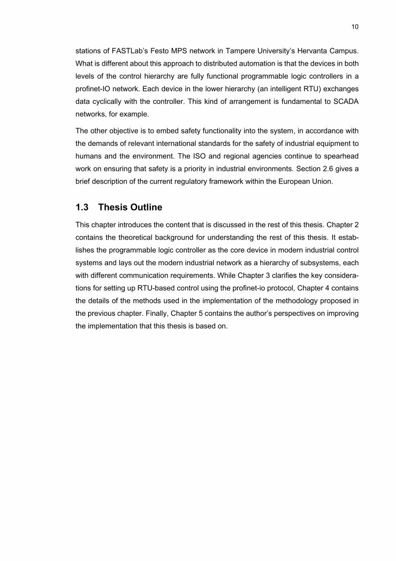
1.3 Thesis Outline
This chapter introduces the content that is discussed in the rest of this thesis. Chapter 2
contains the theoretical background for understanding the rest of this thesis. It estab-
lishes the programmable logic controller as the core device in modern industrial control
systems and lays out the modern industrial network as a hierarchy of subsystems, each
with different communication requirements. While Chapter 3 clarifies the key considera-
tions for setting up RTU-based control using the profinet-io protocol, Chapter 4 contains
the details of the methods used in the implementation of the methodology proposed in
the previous chapter. Finally, Chapter 5 contains the author’s perspectives on improving
the implementation that this thesis is based on.

11
2. LITERATURE REVIEW
The literature review discusses topics fundamental to industrial control technology and
serves as a basis for the understanding of the rest of this thesis. It opens with a discus-
sion of overlapping areas of interest between industrial control and mechatronics and
then goes on to describing the unique requirements of control systems and the technol-
ogies that enable the interconnection of the discrete control units to make modern pro-
duction systems possible. The latter parts of this chapter address the concerns for the
safety of humans and equipment in an industrial environment as well as the methods by
which manufacturers of control equipment ensure that their devices always operate
safely and predictably. It also provides the reader with a view of European regulatory
framework for the manufacturing and usage of industrial equipment.
2.1 Mechatronic Systems in Factory Automation
First mentioned in Japan in 1969, mechatronic systems integrate mechanics with elec-
tronic systems with the aim of improving manufacturing plants. Areas of interest in mech-
atronics include but not limited to signals and systems, computers and logic systems,
sensors and actuators, automatic control, and physical system modelling [10][11] – all of
which are of interest to the factory automation and control engineer. From automatic
packaging and product quality monitoring systems to safety systems and flexible manu-
facturing systems (FMS), these systems have become the mainstay of the modern in-
dustry. Another interesting application domain for mechatronic systems is computer-
aided manufacturing (CAM). Integrated with intelligent control solutions, mechatronic
systems have been responsible for reduced human labour consumption as well as the
improved efficiency of modern manufacturing processes [11].

12
Figure 1: Key aspects of mechatronics
2.2 Automation System Hierarchy: The Automation Pyramid
Every industrial automation system is composed of three fundamental parts: a sensor
for observing the physical world, a controller to process the observation, and an actuator
to effect some change in the physical world. In an industrial setting, the controller can be
a PLC, a DCS, or a PAC, although PLCs are the most widely used. For easy understand-
ing of what is usually a complex network of devices, industrial control engineers have
created a pictorial representation of the layers of automation in a production company.
These layers stacked vertically above one another forms what is known as the automa-
tion pyramid as shown in the two-dimensional representation in Figure 2. The automation
pyramid is a visual example of how technology is integrated in industry.
The supervisory layer is typically composed of HMI and SCADA for setting production
targets and recipes as well as for starting and stopping the production process. While
MES systems (planning level) [12] create realistic production schedules and monitor the
flow of material throughout the entire manufacturing floor, the ERP level represents the
highest level of decision making in industry. The ERP is a suite of applications that inte-
grate with events and data in the lower layers. This system is responsible for decisions
involving sales, invoicing, pay rolls and others.

13
Figure 2:The Automation Pyramid
Apart from the differences in the industry functionality addressed by each layer of the
automation pyramid, a key distinguishing feature between them is the timing constraint
governing decision making at each level. While the enterprise level, for example, might
make decisions based on large amounts of data collected over several weeks or months,
controller communications with RTU and field devices at the other end of the hierarchy
must be completed in milliseconds, or even microseconds for some advanced control
applications and typically involves just a few bytes of data.
2.3 Programmable Logic Controllers
As suggested in the introduction to this thesis, PLCs are at the core of the control of
many modern industrial production systems. These computers, built to withstand the
harsh conditions of the manufacturing environment, drive whole assembly lines or a part
of a manufacturing system. Modern PLCs are also equipped with networking capabilities
which interface with other PLCs and sensor and actuator systems which make it possible
for large manufacturing systems to be composed of networks of distributed PLCs collab-
orating with one another to bring a product to life. Some of these networking systems,
their typical application areas, and their suitability for RTU-based control (one of the main
subjects of this thesis) are discussed in this chapter. With a capability of seamlessly
handling thousands of I/O points, the advent of PLCs led to the elimination of complex,
non-reusable relay systems in the manufacturing industry. The range of capabilities of

14
PLCs have nonetheless improved considerably over the years: they now support ana-
logue signal processing, PID control, and fuzzy logic interfaces among others. The first
PLCs [13] were available to General Electric’s automobile plants in 1969, and in only
two years, they found their way into other industry areas like food and beverage, and
paper processing.
Figure 3: The PLC System [14]
The basic functionality of a PLC [15] is to repeatedly generate control commands for the
system in which it is embedded. It does this by running the user program in an infinite
loop, and the amount of time it takes to run a single iteration of this loop is called a scan
cycle. During each cycle, the CPU reads input data, processes them according to the
user program, and writes the resulting output data. The duration of the scan cycle de-
pends, among other factors, on the amount of I/O data that needs to be accessed, the
size of the user program, the presence of remote I/O, and the baud rate of communica-
tion between the CPU and I/O modules. To enable fast processing times, the CPU does
not normally read directly from it peripheral I/O units (unless it is specifically instructed
to do so) in each scan cycle but rather from buffered data in its own system memory.
This part of the memory is called the process image (PI). Consequently, there is the
process image of inputs (PII) and the process image of outputs (PIQ). Reading the sta-
tuses of the peripheral inputs to the PII and writing the statuses of the PIQ to the periph-
eral outputs is an internal task of the operating system. Therefore, each scan cycle more
precisely involves the following steps in sequential order [16]:

15
1. Processing of internal tasks of the operating system.
2. Writing of states from the PIQ to the physical outputs.
3. Reading of the physical input states into the PII.
4. Processing of the user program.
5. Go back to Step 1.
The process image ensures that the user program has a consistent representation of the
process signals throughout step 4. If the process signals change during this time, the
update is not written to the process image until the next scan cycle. Figure 3 shows the
basic units that make up a PLC.
2.3.1 The IEC-61131 Standard
The IEC-61131 is the internationally recognized standard for every aspect of PLC devel-
opment. It covers hardware and software requirements of PLCs [17] as well as commu-
nication interfaces (parts 5 and 9 of the standard). As the capabilities of PLCs have been
improved tremendously since their invention, the newest version of the standard [18] as
at the time of writing this thesis has ten parts covering important aspects like communi-
cations, equipment requirements, programming languages, fuzzy control programming,
and functional safety, which is another aspect of this thesis.
Part 3 of this standard covers the programming languages and the software model for
PLCs. The standard recognizes five programming languages, including 3 graphical lan-
guages and two textual languages, each one more suited to certain kinds of tasks. The
textual languages are Sequence Function Chart (SFC) and Structured Text (ST), while
the graphical languages are Ladder Diagram (LD), Function Block Diagram (FBD), and
Sequence Function Chart (SFC). The implementation presented in chapter 4 of this the-
sis uses one graphical language (LD), and one textual language (ST). Although each
PLC manufacturer has its own graphical environment and libraries for developing for
PLC applications, the vendor-independent organization PLCopen continues to work to-
wards standardization of the program components and interfaces to ensure a lower
learning barrier for programmers switching between systems developed by different
manufacturers.
2.3.2 Safety PLCs and Fault-tolerant PLCs
A safety PLC is one that is certified for use in a safety-critical application. These devices
are built to meet internationally recognized safety standards, primarily the IEC 61508 (a
generic industrial safety standard) and IEC 62061 (a safety standard for programmable
electronic devices), both of which are discussed in section 2.9, and part 6 of the IEC
16
61131 standard adapts the requirements laid down in these two standards to PLCs [17,
p. 15]. The purpose of a safety system is to bring a machine or an industrial process to
a safe state as quickly as possible when the safety system is triggered. More specifically,
a safety system ensures that the machine or process fails in a safe (predictable) manner
when triggered, for example, by commanding a valve to a specific position to avoid the
spillage of hazardous material or by stopping a motor or a robot to avoid harm to humans.
Control systems with a safety function are called safety related control systems (SRCS).
Compared to standard PLCs, functional safety programmable logic controllers (FS-PLC)
[19] – as IEC 61131-6 describes safety PLCs – are new to the industrial automation
scene [20] and are gradually being adopted into industrial control systems. Until their
arrival, decreasing the risk of machinery followed the pattern of intrinsic safety, which
meant that physical guards were used to separate humans from machinery or areas with
a risk of hazardous material. Safety systems on the shop floor were, therefore, logically
separate from machine control systems. With functional safety, however, safety and con-
trol systems can coexist in the same electrical system. IEC 61131-6 also stipulates that
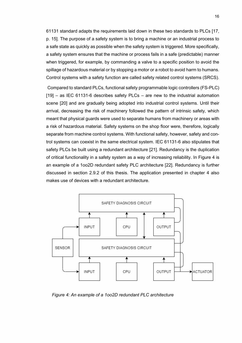
safety PLCs be built using a redundant architecture [21]. Redundancy is the duplication
of critical functionality in a safety system as a way of increasing reliability. In Figure 4 is
an example of a 1oo2D redundant safety PLC architecture [22]. Redundancy is further
discussed in section 2.9.2 of this thesis. The application presented in chapter 4 also
makes use of devices with a redundant architecture.
Figure 4: An example of a 1oo2D redundant PLC architecture

17
While some manufacturers (e.g. Mitsubishi) [21] offer PLCs that are designed exclusively
for functional safety use, others (e.g. Siemens) offer products that integrate safety and
standard control into one unit. These integrated units, in addition to issuing standard
control signals, are also capable of monitoring and controlling safety I/O (for example,
emergency stop buttons, safety relays, and safety laser scanners) built into the manu-
facturing process. This simplifies data sharing between the safety-related and non-
safety-related parts of the control system and aids both maintenance and troubleshoot-
ing. Safety PLCs also have inbuilt security features for preventing unauthorized modifi-
cation of the safety program.
For certain industrial processes, especially in the process industry, downtime as a result
of the failure of a component failure can comes with huge financial losses. Therefore,
shutting down the process in the middle of a production batch is unacceptable. The use
of redundant design in the control of such production systems rather ensures that the
production process continues to operate (even if at reduced capacity) if a component
fails. Fault-tolerant PLCs have been developed for such industrial application environ-
ments. It is generally believed that the cost of production stoppage positively correlates
with the need for a fault-tolerant system [23].
2.4 Requirements of an Industrial Control Network
The purpose of the earlier parts of this chapter is to establish the PLC as the computer
at the core of the control of the industrial systems of concern (because an industrial
control system can also be a SCADA or DCS). However, as large manufacturing systems
are typically composed of a network of devices in a hierarchy that may be several layers
deep [24, p. 2], it is imperative to also describe the technologies that enable the inter-
change of information between PLCs, RTUs, and I/O devices in a factory setting. Section
2.2 already describes the standard model for the hierarchical interconnection of devices
in a manufacturing enterprise. From the pyramid, one can mentally picture a system of
PLCs (which may also be hierarchical, depending on the setup) in the control layer con-
nected to monitoring and data acquisition devices in the upper layer, and to RTUs and
field devices in the lower layer. The pyramid is a representation of the integration of
different technologies in the manufacturing industry.
Based on the nature of the information interchange at each layer of the pyramid, indus-
trial networks are often be subdivided into three fundamental levels [25]: information,
control, device level, as shown in Figure 5. The device level network consists of intelli-
gent field devices which collect small data items (typically a few bits or bytes) cyclically

18
from connected sensors and actuators and transfers them to the controller for pro-
cessing. Smart RTUs belong to this level. The information level primarily carries large
units of data on an irregular basis, for example, the operator console pulling historical
production records from databases. The control level network carries a mix of cyclic,
time-critical data exchanged between controllers and irregular data concerning alarms
and events within and below this level.
Figure 5: Layered structure of an industrial automationnetwork (adapted from [26])
Because the exchange of information between control systems layer (level 1) and mon-
itoring and data acquisition systems (level 2) do not necessarily require the same strin-
gent constraints as the mostly cyclic exchange with field devices, the control network as
discussed here is therefore limited to the interconnection between controllers, which may
also connected intelligent field devices (including RTUs) and sensors and actuators in
the lowest rung of the industrial automation hierarchy – levels 0 and 1 in the pyramid.

19
Table 1: Typical differences between industrial and conventional networks [24]
Industrial
Conventional
Primary func-
tion
Control of physical equip-
ment
Data processing and transfer
Applicable Do-
main
Manufacturing, processing,
and utility distribution
Corporate and home environments
Hierarchy Deep, functionally sepa-
rated hierarchies with many
protocols and physical
standards
Shallow, integrated hierarchies with
uniform protocol
Failure Severity high
low
Reliability Re-
quired
high moderate
Round trip
times
250µs – 10ms
50+ ms
Determinism high
low
Data Composi-
tion
Small packets of periodic
and aperiodic traffic
Large, aperiodic packets
Temporal Con-
sistency
required
not required
Operating Envi-
ronment
Hostile conditions, often featuring high levels of dust, heat and vibration
Clean environments, often specifi-
cally intended for
Although the increasing adoption of ethernet-based protocols in industrial networks [27]
might suggest similarities in industrial and commercial networking needs on a physical
level, the harsh environment of the industrial workplace necessitates that networking in-
frastructure possess enough ruggedness to withstand adverse conditions like moisture,

20
temperature, electrical noise, and vibration. Beyond the physical level, the fact that in-
dustrial networks are designed primarily for monitoring and controlling real world actions
rather than for mere transport of data from point to point suggests a fundamentally dif-
ferent quality of service (QoS) considerations than those of commercial networks. Some
of these considerations are compared in Table 1 and are further expounded on hereafter.
Determinism: Because delays in information delivery can have adverse effects on the
performance of a manufacturing system [24], it is necessary that control signals in an
industrial network be delivered in a timely and predictable manner. Such adverse effects
may compromise the quality of the product or include injury, loss of life, or a risk to the
environment [28]. In a deterministic network, there is an upper bound on the time it takes
for information to be relayed from one end of the network to another, irrespective of the
network traffic. Throughput, latency, and jitter are three measures used to characterize
the determinism of a control system [26, p1]. While throughput measures “the average
rate of successful message delivery over a communication channel”, latency can be de-
fined as the observed time delay between sending a signal from a source and receiving
it at its destination, and jitter is the average variability in network latency. For best per-
formance, information exchange in a control network should have high throughput, low
latency, and low jitter.
Determinism is the key performance indicator for an industrial automation system net-
work protocol and the primary measure of network reliability [26]. The suitability of the
fieldbus protocols (section 2.6) for industrial applications is largely tied to their capability
for deterministic communication. Ethernet, on the other hand, was not used for carrying
control commands in industry until the modifications that paved the way for suite of pro-
tocols now referred to as industrial ethernet, despite its huge success in conventional
networks.
Synchronization: Transmissions in an industrial network may include cycle-based I/O
data as well as event-based information, for example, alarms and safety signals. The
requirements for determinism mean that data must be transmitted within a set time period
even though there may be a variation in the period for sampling and transmitting data
across devices. Furthermore, the correct processing of events requires accurate syn-
chronization between devices in accordance with the IEEE 1588. Synchronization re-
quires both determinism and a specific latency [29].
Realtime capabilities: Beyond the determinism in the sending of control signals in an
industrial control system, there are applications with timing constraints such that the pro-
cess fails, or their integrity is compromised if control signals miss their deadlines. Clearly,

21
a basic requirement for the control system in such an application is that it must be deter-
ministic, although determinism alone does not guarantee that real-time requirements of
the application will be met. As an example, consider a simple application where control
signals are issued based on transitions in a digital input signal. If the signal changes in
every 10ms and the controller’s scan cycle takes say, 12ms, then some transitions in the
monitored signal will inevitably go unnoticed by the controller. For an application with a
hard real-time requirement, this situation is impermissible; a soft real-time requirement
means that the system is able to cope with some deadline misses in the control signal.
For a real-time application, care must be taken to ensure that the choice of underlying
network satisfies this requirement. According to [29], real time is defined as “sufficiently
rapid to achieve the objectives of the application”.
2.4.1 The ISO/OSI Reference Model
This sub-section leads directly to the networking protocols standardized for use in indus-
trial applications. Having discussed the communication requirements of a typical indus-
trial control network, it becomes important to also describe how the design of industrial
networking protocols ensure that these requirements are met and how they may be ap-
plied to RTU-style operation between controllers and intelligent field devices.
The ISO/OSI model is an abstraction of the communication functions of a computing
system and is standardized in ISO/IEC 7498-1. It is made up of 7 layers, each with its
own suite of protocols and unique responsibilities in data transfer between two comput-
ers. As an industrial automation system is often composed of devices (controllers, smart
RTUs, etc) from multiple vendors, a standardization of the communication functionalities
between multiple systems is, therefore, a necessary step towards interoperability. Figure
6 shows how data flows between these layers in an interchange between two user ap-
plications in a communication relationship.

22
Figure 6: Layers of the ISO/OSI reference model
1: physical layer 2: data link layer 3: network layer 4: transport layer
5: session layer 6: presentation layer 7: application layer
Layers 1 – 3 are hardware layers and layers 5 – 7 are software layers. Layer 5 intercon-
nects the two. The networking equipment along the communication channel can be a
switch, or a router if the communicating computers are on different subnets, or a gateway
device if there is a difference in the protocols used in the layers.
Because industrial control applications often require data to be delivered promptly and
predictably (determinism with synchronization), the passage of time can invalidate data
that misses its delivery deadline. Clearly, determinism requires that data flow in the OSI
stack cannot be probabilistic. Also, bi-directional transmission in a multi-controller sys-
tem must ensure that there is no data collision in the physical medium. For these rea-
sons, the fieldbus protocols are optimized for carrying process control by bypassing the
ISO/OSI layers that are associated with non-time-critical functionality and those that in-
troduce data that may lengthen delays more than an industrial application can tolerate –
typically layers 3 through 6, which are only used or non-time-critical data. The definition
of the data link layer (layer 2) functionalities, therefore, happens to be one of the most
critical aspects of a fieldbus specification. The management of access to the physical

23
medium (MAC protocols) and collision avoidance must be implemented in this layer, and
this highlights how critical this layer is towards achieving the requirements of industrial
control applications.
Figure 7: OSI Reference Model as applied the fieldbus model (right)
MAC protocols are generally classified as either distributed or centralized [30][31], but a
detailed discussion is beyond the scope of this thesis. However, how the OSI model can
be utilized to fulfil RTU-style communication in a network of PLCs is discussed within the
next section. A subsequent section describes the mechanism through which a popular
industrial networking protocols (Profinet-IO) can be used to fulfil this need and forms the
basis for the methodology and implementation presented in chapters 3 and 4, respec-
tively.
2.5 PLCs as Remote Terminal Units
The industrial automation market is replete with microprocessor-based devices for mon-
itoring and controlling other field devices. The many RTUs on the market also vary in
functionality and networking capabilities just as they are well adapted to serve a specific
industrial application niche. The unifying functionality for all RTUs, however, is their use
as decentralized I/O units for a control unit, although some possess the capability to
execute limited control actions on their connected field devices. The decentralized sys-
tem of devices used for this thesis, however, uses fully functional PLCs as both the cen-
tral controller and a system of decentralized intelligent RTUs.
Clearly, in addition to the communication requirements of industrial control systems dis-
cussed in this chapter, using a PLC as an intelligent RTU further requires that it can
respond to remote control signals from a higher controller. Higher in this sense is in the

24
context of the automation pyramid, as RTUs are field-level devices. This is a way of
operating an industrial control network as a system of distributed intelligent field devices.
Starting from section 2.7, this thesis describes an industrial communication protocol that
is well suited for this purpose. The control engineer who wishes to redesign their plant to
an RTU-style operation may apply this to fulfil their application’s needs.
In chapter 3 are design decisions to consider in implementing such a system, and chap-
ter 4 provides a concrete example of implementing such a system with an industrial
ethernet protocol.
2.6 The Fieldbus Standard
Fieldbuses are a specialized class of communication protocols designed for industrial
applications. While the oldest industrial control systems (which were mechanical) gave
way to relays and analogue electronic control loops, the newer system still required sev-
eral kilometres of wiring both to the field and for the internetworking of control equipment.
However, with advancements in microcontroller development came the need for more
efficient communication protocols with their own unique set of requirements for the man-
ufacturing workplace. How these requirements differ from conventional networks are dis-
cussed in section 2.4. To promote interconnectivity among devices from different ven-
dors, an attempt to develop a single international standard [32] started in the 1980s but
this, unfortunately, led to contention among the major device manufacturers, now com-
monly referred to as the ‘fieldbus wars’. The resolution was the adoption of 8 proprietary
standards [33], each one more suited for a specific application domain. This is the IEC
61158: Digital data communications for measurement and control – fieldbus for use in
industrial control systems.
A fieldbuses network is an interconnection of intelligent controllers, sensors, and actua-
tors. This means they appear everywhere within and below the control layer of the auto-
mation pyramid. They have the advantages of reducing wiring costs and are also capable
of carrying diagnostic messages as well as process signals between networked devices.
The presence of diagnostic messages helps in troubleshooting and reduces downtimes
of industrial production systems. Examples of popular fieldbus protocols are Profibus,
WorldFIP, Interbus, and Foundation Fieldbus.
2.7 Industrial Ethernet
Ethernet is clearly the dominant technology for conventional computer networks, as it is
commonly found in the office setting as well as enterprise networks. Its inherent lack of

25
determinism, however, initially presented challenges for its use in the lower layers of the
automation hierarchy, until the invention of smart switches. The technology has since
found its way into the manufacturing shop floor both for remote I/O networking and for
the interconnection of control systems and is gradually replacing fieldbus networks [34].
It has brought uniformity in industrial networking technology, making vertical integration
of ERP systems with control networks an easy choice. The technology is defined in a
series of IEEE 802.3 standards. In the year 2019 alone, industrial ethernet accounted for
59% of all new factory automation installations globally, compared with 52% in the pre-
vious year [34].
Standard Ethernet defines only layers 1 and 2 of the OSI model and uses a distributed
medium access protocol called CSMA/CD for bus arbitration. If two nodes attempt to use
the physical medium at the same time, this results in a collision which is detected by both
participants (carrier sense). Under such circumstance, each node waits a random
amount of time in accordance with the binary exponential back-off (BEB) algorithm [35]
before attempting a re-transmission. Reaching a maximum number (16) of retries also
means the message is considered undeliverable, even in the absence of errors on the
link. An industrial control network may not be able to tolerate such loss of critical control
or safety data. This absence of determinism on regular ethernet is the reason the use of
the technology is mostly confined to information technology networks. Furthermore, the
average message delay is expected to increase with the amount of traffic. Nevertheless,
ethernet offers higher bandwidth (up to 100Mbps for Fast Ethernet, 1 Gbps for Gigabit
Ethernet) than any fieldbus protocol, and up to 1500 bytes of data in a single frame.
Fieldbus protocols were generally designed for the fast exchange of small amounts of
data (Table 1).
Industrial ethernet is currently a suite of over 20 protocols, each one from a different
vendor. Its most prominent protocols [34] are Ethernet/IP, Profinet, and EtherCAT. Each
one builds on top of standard ethernet to bring it up to the required performance for
control applications. However, a key drawback of the many industrial ethernet technolo-
gies is the lack of compatibility [36] between them, thereby posing a challenge to building
control networks from devices from multiple vendors and prompting talks of an ‘industrial
ethernet war’.
The latest development in future ethernet technology is Time Sensitive Networking
(TSN). According to the IEEE [37], the purpose of this is “to provide deterministic ser-
vices through IEEE 802 networks, i.e., guaranteed packet transport with bounded
latency, low packet delay variation, and low packet loss”. TSN (IEEE 802.1Q) is a

26
layer 2 technology that exposes a number of services on standard ethernet that will en-
able the control engineer to configure the network to suit the time constraints of their
application and also to confirm that the network will always be able to fulfil these require-
ments. The system is meant to achieve this through a central network controller (CNC),
which negotiates the path of data between any two nodes as part of network configura-
tion [38].
2.7.1 Profinet-IO (PNIO)
Profinet is a member of the industrial ethernet family, and PNIO is one of 2 industrial
automation perspectives of the protocol, the other being Profinet-CBA (component-
based automation). While PNIO focusses on data exchange between controllers and
decentralized intelligent devices (remote I/O capability) [39][40], profinet-CBA is
profinet’s concept of distributed automation. With at least 25 million nodes as of 2018
[41], profinet is one of the world’s most popular industrial ethernet protocols [34].
Profinet-IO complies with the international standards IEC 61158 and the IEC 61784. With
reaction times in the range of 5 – 10ms, it provides adequate responsiveness for most
factory automation applications. With a special ASIC, version 3 of profinet also supports
high-accuracy motion control applications with cycle times below 1ms and a jitter of less
than 1us.
Figure 8: PNIO RT data frame [44]
Switched ethernet brought determinism to the basic ethernet protocol and this is what
profinet is built on [42]. In a switched network, ethernet nodes communicate directly with
a switch which forwards data to the destination by using MAC addresses of the sender
and receiver when real-time data does not have to travel across network boundaries,
otherwise the UDP/IP stack is used. Furthermore, a switched network creates separate
logical channels for sending and receiving data, thereby enabling full-duplex communi-
cation and eliminating data collision [43]. A PNIO network, therefore, has no need for a
collision detection protocol as in standard ethernet. Ethernet’s priority-based flow control

27
(VLAN tagging of frames according to IEEE 802.1Q) [44] also ensures that profinet real-
time frames (identified by the standardized etherType 0x8892) get the highest transmis-
sion priorities [45]. Figure 8 shows the structure of a profinet-IO data frame for real-time
communucation.
Unless it absolutely must, communication in a control network does not use all layers of
the OSI model in order minimize transmission latencies. For non-time-critical processes
like device configuration and network diagnostics, a PNIO network uses TCP/IP or
UDP/IP protocol suites. Real-time (RT) communications, however, bypass these layers
as shown in Figure 8. The isochronous real-time (IRT) channel is reserved for high-ac-
curacy applications that require a jitter of less than a microsecond, for example, closed-
loop motion control. IRT traffic requires accurate time synchronization between the com-
municating devices as well as a special hardware. UDP/IP is also used when RT data
needs to be transmitted across LANs [46].
Figure 9: Profinet communication channels
In conveying RT, IRT, as well as non-RT data on the same physical channel, PNIO uses
a deterministic method known as TDMA to control access to the physical medium [47]:
IRT and non-IRT data are transferred on alternate time slices. Typically, the network can
be configured to specify what fraction of a cycle is to be used for IRT traffic. During this
fraction, all non-IRT data is buffered by the network switch until the IRT traffic phase is
over.
28
Figure 10: Periodic alternation between IRT and non-IRT traffic
The PNIO application layer defines a profinet application process (AP) which provides
specific services defined in several PNIO application service elements (ASE). Among
these are the io-data ASE for the cyclic exchange of process input and output data, the
diagnosis ASE for reading channel and manufacturer-specific diagnostics, the record
data ASE for generic read-write services, and others for alarms and application relation-
ship management. The details of these can be found in [40].
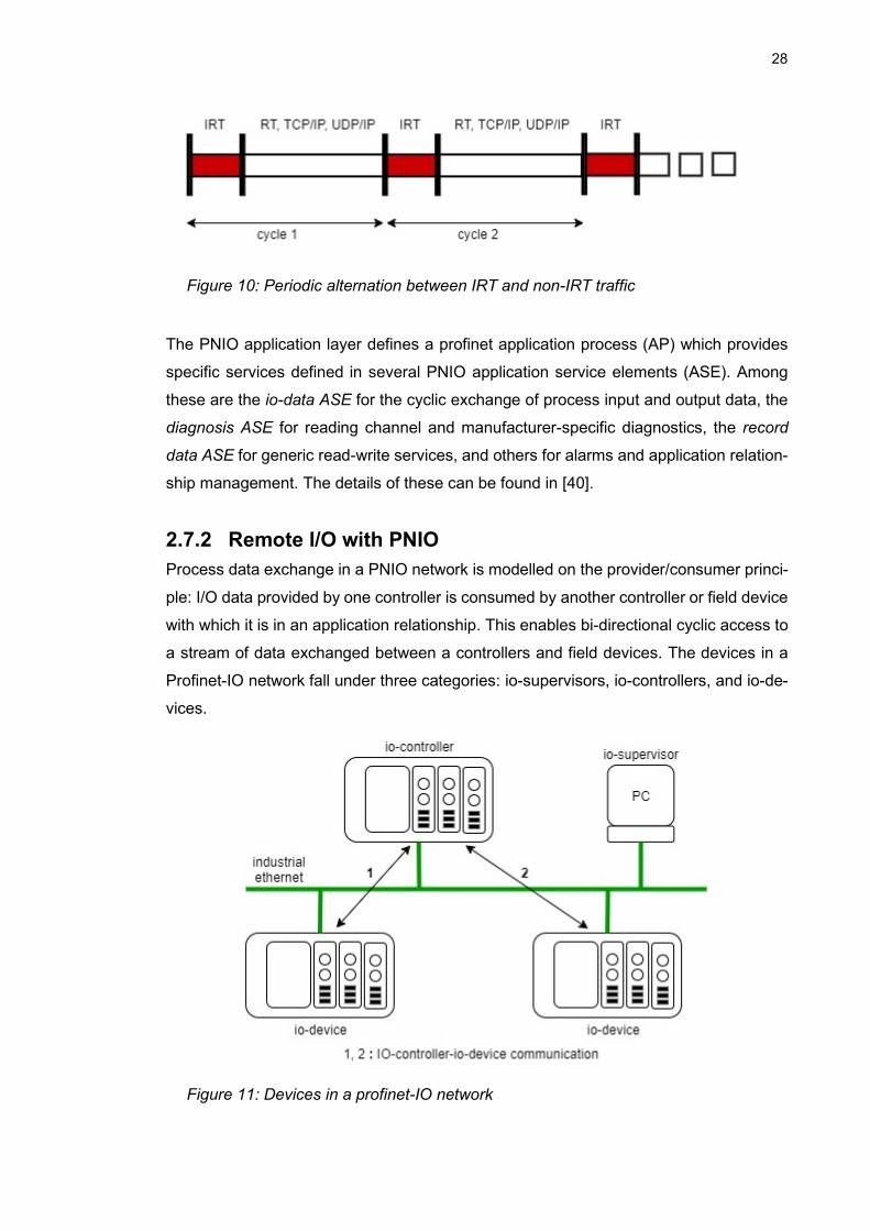
2.7.2 Remote I/O with PNIO
Process data exchange in a PNIO network is modelled on the provider/consumer princi-
ple: I/O data provided by one controller is consumed by another controller or field device
with which it is in an application relationship. This enables bi-directional cyclic access to
a stream of data exchanged between a controllers and field devices. The devices in a
Profinet-IO network fall under three categories: io-supervisors, io-controllers, and io-de-
vices.
Figure 11: Devices in a profinet-IO network
29
Cyclic exchange of process data in a PNIO network requires one or more io-controllers
with one or more io-devices. The io-controller is typically a PLC or a DCS receiving pro-
cess data from decentralized field devices (intelligent RTUs) and issuing control signal
signals to them. The io-controller is also responsible for the establishment of communi-
cation relationships (for I/O data, alarms, etc.) with its assigned RTUs during system
start-up. The io-supervisor is the PC for configuring and programming the system or an
HMI device for monitoring the network. A shared io-device can be configured to com-
municate with more than one io-controller. As an io-device can also be assigned as io-
controller to other io-devices, PNIO enables the creation of hierarchical industrial net-
works of controllers and intelligent field devices.
2.8 Safety communication: ProfiSafe
Apart from carrying process data and diagnostics, industrial control and communication
systems have evolved over time to process and transmit safety data as well. Traditional
implementation of safety systems in the production industry used to be by relay networks
physically separated from control systems because regulations prohibited the use of mi-
crocontroller-based safety systems [48]. However, increased trust in the capabilities of
PLCs and industrial PCs ushered in an era (through IEC 61508) in which both I/O and
safety data are conveyed through the same networks and are replacing hard-wired relay-
based safety applications.
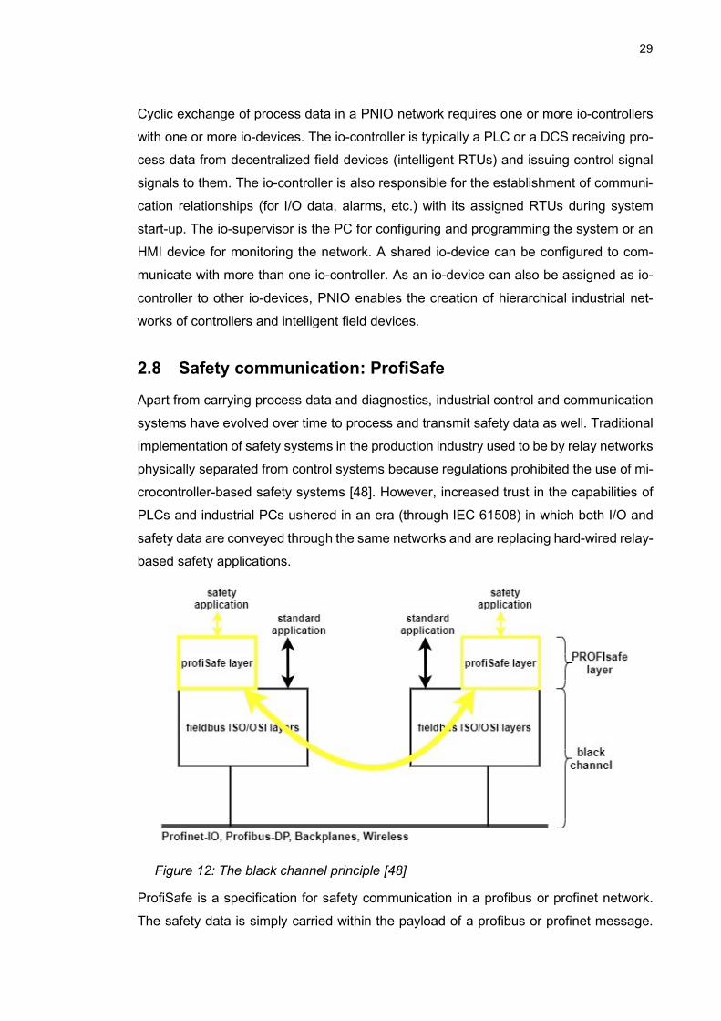
Figure 12: The black channel principle [48]
ProfiSafe is a specification for safety communication in a profibus or profinet network.
The safety data is simply carried within the payload of a profibus or profinet message.

30
This allows the use of PLCs with integrated but logically separate safety processing. Like
most other safety fieldbus communication protocols, profiSafe is architected on the black
channel principle: this means that the safety communication takes place transparently
irrespective of the underlying network, which merely conveys the message between an
F-Host and an F-device and does not need to have safety-rated devices (e.g. repeaters,
switches, and backplane buses). Therefore, all measures for transmitting safety data are
implemented in a safety communication layer (defined in IEC 61784-3). Figure 12 depicts
this arrangement for the profiSafe profile.
2.9 Functional Safety of Machinery
All industrial production systems carry are a potential source of risk to the environment,
or humans, or even to the machines used in the process. Because it is generally known
that it is not possible to make a machine 100% safe, functional safety aims to reduce the
risk associated with operating industrial equipment to a level that is considered tolerable.
Within the European Union, for example, machine manufacturers have the responsibility
of ensuring that equipment do not constitute danger to humans or the environment. The
following sections of this chapter discuss the relevant standards applicable to the imple-
mentation of safety systems in industry as well as methods of risk reduction.
Functional safety is the part of overall safety of an equipment that ensures it responds
correctly to input signals and uses active systems to mitigate risk in a way that is predict-
able. Using active electronic systems ensure that the built-in mechanism can activate to
reduce or eliminate risk when necessary. A mobile robot stopping in response to sensing
an unexpected object in its path is an example of functional safety. Using heat-resistant
material as a safeguard for overheating in a machine isn’t functional safety, since it is
not based on active components.
2.9.1 Safety Standards in the Automation Industry
There are many standards concerning the safety of industrial equipment, and these can
be international or regional standards. Some also depend on the specific industry of con-
cern. In the European Union, three organizations (CEN, CENELEC, and ETSI) are offi-
cially [49] responsible for creating a framework for the development of European stand-
ards and are collectively recognized as European standards organizations (ESO). The
standards created by these bodies are therefore called European national standards (EN
standards). However, while CEN standards focus on sectors other than electrotechnical
(handled by CENELEC), ETSI standards are directed at the telecommunications indus-

31
try. On occasion, European standards are developed jointly with ISO through joint tech-
nical committees and the results of such collaborations are reflected in the EN ISO stand-
ards.
From January 2012, the erstwhile effective EN 954-1 standard has been replaced [50,
p1:6][51, p. 141] by the EN ISO 13849-1 (Safety of Machinery, Safety related parts of
control systems, General principles for design) and the EN 62061 (Safety of Machinery,
functional safety of safety-related electrical, electronic, and programmable electronic
control systems). The functional safety rating of industrial machinery is, therefore, cur-
rently being assessed in accordance with these new standards, which are also harmo-
nized [52] to the European Union Machine Directive.
The EN 62061, like other technology-specific safety standards, is based on the require-
ments of IEC EN 61508 (Functional Safety of Electrical/Electronic/Programmable Elec-
tronic Safety-related Systems) [53], which is considered the umbrella standard for func-
tional safety because its requirements are applicable to a wide range of industries [54].
As a result, there are several other industry-specific functional safety standards in use in
accordance with the field of the application, for example, IEC 61513 for nuclear power
plants, IEC-61511 for the process industry, and IEC 62304 for medical device software.
The IEC 61508 standard also defines [55] a safety life cycle (SLC) process for that covers
the design, implementation, modification, as well as the close-down of a safety-instru-
mented equipment.
ISO 13849 and EN 62061 are jointly the standards for the machinery industry. While the
former uses PL ratings (Performance Level) as a measure of functional safety, the latter
uses what it called a safety integrity level (SIL). Although a correct application of either
standard results in comparable levels of functional safety, the EN 62061 specifically ad-
dresses programmable electrical/electronic parts of control systems, some of which were
used in the implementation part of this thesis work, ISO-13849 is technology-neutral and
may be applied to both electronic and non-electronic systems.
2.9.1.1 Risk Assessment
The ISO 12100 (Safety of Machinery – General Principles for Design – Risk
assessment and risk reduction) standard ”specifies basic terminology, principles, and a
methodology for achieving safety in the design of machinery” [56]. It also provides a
means of estimating risk, and guidance for the risk reduction process starting from the
design stage of a machine. The risk assessment procedure (Figure 13) is presented as
a sequence of logical steps that would guide manufacturers in making machines that can
be certified safe in accordance with the Machine Directive. The purpose is to identify the

32
risk of hazards, estimate potential harm to users and the environment, and consequently
take remedial action to reduce them as much as possible. A risk, according to this
standard, is a probabilistic concept defined as ”the combination of the probability of the
occurrence of harm and the severity of that harm”. The risk assessment chart is
composed of three parts: risk analysis, risk evaluation, and risk reduction. ISO 12100
addresses safety concerns that extend beyond the requirements of functional safety.
Figure 13 : A risk asssessment chart [57]

33
If a risk identified in the risk evaluation procedure is not considered tolerable (or accepta-
ble), then it is necessary to provide a mechanism for the reduction of such risk. The
design and implementation of such a mechanism can then be done in accordance with
EN ISO 13849 or EN 62061 [57], as shown in Figure 14. It is generally agreed that the
concept of ‘zero risk’ does not exist in the real world. It is therefore still possible that there
is some residual risk even after implementing a risk reduction mechanism. In the United
Kingdom [58], for example, safety regulations recommend that the level of residual risk
be as low as reasonably possible (ALARP).
Figure 14: Functional safety of machinery [57]
2.9.2 Redundancy and Voting Architectures
Redundancy is the duplication of critical functionality in a safety-instrumented system: if
one (maybe more) of the devices providing the functionality were to fail, the control sys-
tem can either continue to rely on the signals from the other device(s) or put the protected
system in a safe state, depending on the voting style of the safety devices. Many safety
systems employ a deenergize-to-trip philosophy, which ensures that current flows
(closed contacts) through the safety device(s) during normal plant operation and the pro-
tected equipment shuts down safely or is unable to start if the safety contacts are open
(safety system is not active). In a two-sensor safety functionality like the one shown in
Figure 15a, for example, if one of the switches suffers a failure, the protected equipment
continues to get the safety signal through the other one: a vote (trip) from any one out of
the two switches is all that is necessary for the safety functionality to be available on
demand, and is therefore known as a 1oo2 (one out of two) architecture. The arrange-
ment in Figure 15a is only one example of a well-known voting architecture generally
referred to as MooN (M out of N). Where N is greater than 1, we have a multichannel

34
system. A single sensor (single channel) system is a 1oo1 arrangement: there is no re-
dundancy. Also, an MooN system where 𝑀 = 𝑁 has no redundancy: a failure in any one
of the signal paths means that the safety functionality is no longer available. Other com-
monly used voting arrangements are the 2oo2 and 2oo3 systems, shown in Figures 15b
and c, respectively.
Figure 15: MooN Voting Architectures (a) 1oo2 (b) 2oo2 (c) 2oo3
On the contrary, there are safety systems where using the deenergize-to-trip approach
is impracticable or might even constitute a risk: a situation of conflicting readings from
altimeters in a in-flight control system, for example, would be better handled by notifying
the pilot than shutting down any part of such a life-critical system. Nevertheless, there
are other systems where the energize-to-trip philosophy proves to be the safer choice,
despite their apparent risk of failure due to undetected circuit breaks or failure of the
power supply system. Modern safety systems overcome this challenge by using safety-
certified uninterruptible power supply (UPS) systems equipped with low-power pulsing
circuits that constantly check for any discontinuity in the signal path. As a matter of fact,
the choice between the approaches depends on the nature of the hazard or risk that the
safety-instrumented functionality is designed to hinder [59].
2.10 Safety-instrumented Systems
The discussion on voting architectures is a necessary step toward understanding a fea-
ture that is fundamental to the design of systems with inbuilt safety mechanisms. In fact,
understanding the configuration of the devices used in the implementation of this thesis

35
would be difficult without previous knowledge of redundant wiring of safety-instrumented
electronic devices. Safe instrumentation uses a combination of sensors and logic solvers
to ensure the equipment poses minimal risk throughout its lifetime.

36
3. METHODOLOGY
This chapter prepares the ground for the implementation in the next chapter. The previ-
ous chapter establishes the role of the underlying network in achieving RTU-type com-
munication interchange in a network of PLCs. Although this thesis does not attempt to
comprehensively answer the question of network selection in a control network – which
is an entirely separate topic – it spells out the fundamental characteristics that would be
required in a communication protocol for controller-RTU data exchange in a factory set-
ting. This chapter concerns typical design decisions that the control engineer would have
to make in implementing such a system. It also brings the final phase of this thesis into
perspective, providing justification for the choices that were made in implementing RTU-
style communication with specific hardware.
The equipment used in this thesis are two modular Festo stations. Each one can be
considered a mechatronic unit of multiple sensors and one or more motors, pneumatic
grippers, and air slides, conveyors, and other actuators typically found in a factory auto-
mation system, with a PLC as the control unit.
3.1 Physical Layout of the Network
The work on which this thesis is based concerns only two of the Festo stations, and
Figure 16 shows the physical layout of this section of the production plant to give the
reader a perspective on the physical setup. The physical layout of the larger Festo net-
work is shown in Appendix F. The transport station is both physically and logically the
central station for the production system. Its main hardware is a system of sensors for
pallet and workpiece detection, conveyors for moving pallets around the production sys-
tem, and six pneumatic actuators for stopping pallets at strategic locations where work-
pieces undergo testing and various pre-processing activities before they are made into
a product (a pneumatic cylinder). The sensors and actuators on the conveyor form an
AS-I network whose I/O modules located around the six stopping points S1 through S6.

37
Figure 16: Part of the production network
The production area is bounded by walls and light beams from safety laser scanners as
depicted in the Figure 16 and Appendix E. Each station is also equipped with a force-
guided relay which operates according to the energize-to-trip principle discussed in
Chapter 2. These are meant to disconnect electric power from the local I/O units in case
of an emergency. These devices, together with safety I/O modules in the transport
station, make up the safety system.
3.2 Device Roles
Before making the decisions that will influence how the programs on the ends of the
communication link will be structured, it is important to define the function of each device
in the system described in the previous section.
The transport station is physically and logically at the centre of the production system: it
controls the main resource that the operation of each of the other stations depend on. It
is logical to make this the top-hierarchy io-controller in a profinet-io network since this
station interacts directly or indirectly with all the others. The handling station PLC there-
fore serves as an RTU (io-device). If the Festo production system is likened to a fully
functional organism, then in a profinet-io setting the transport station can be likened to
its nervous system with its controller as the brain while the other stations can be likened
to specialized body systems. Each RTU captures its own local I/O values and sends
them to the controller which evaluates them and determines the appropriate response.

38
This is a case of centralized control with distributed field devices (RTUs). For the rest of
this chapter and the next, the io-device in the system will be referred to as the RTU while
the io-controller will simply be referred to as the controller.
3.2.1 Principle of Data Exchange
I/O data exchange in a profinet-io system is based on the provider-consumer model.
Exchanged data are available in pre-configured transfer areas. Conceptually, one can
imagine the transfer areas as the parts of each participant’s (controller or RTU) process
image (PI) which is accessible to the other participant. For bi-directional profinet-io ex-
changes, a transfer area is set up for each direction of I/O data transfer. On the RTU
side, all that is needed of the user program is to logically map transfer areas to the local
I/O in order to give the controller access to them. On each end of the logical link, the
controller (or RTU) writes control commands (or I/O data) to its own transfer area outputs
and they become available at transfer area inputs in the RTU (or controller).
Figure 17: PNIO data exchange principle
The arrows on the right side of the RTU PI represent mappings between the process
image of the local I/O and the transfer areas. This is done in the user program. With PII
and PIQ available in the transfer area outputs, the controller has real-time access to the
values of the RTU’s I/O. from the perspective of the controller, communicating with the
RTU is similar to communicating with a distributed I/O [60]. The user program in the
controller evaluates the remote I/O alongside its own local I/O and returns RTU control
signals to the transfer area outputs which map directly to the RTU transfer area inputs.
3.3 Program Design
In a large profinet-io system, a key point of concern is the effective use of the communi-
cation channel. With multiple levels of control between io-controllers and io-devices with

39
subordinate I/O systems, update times can be affected by the size of the transfer areas.
The larger the transfer area, the higher the bandwidth demand. Furthermore, the amount
of decentralization in control functionalities as one moves down the hierarchy can also
determine how much data needs to be transferred between io-devices and controllers.
The decisions that can help in alleviating these concerns and how they apply to the im-
plementation in Chapter 4 are addressed in the rest of this section. The total bandwidth
used at the io-device is the sum of the bandwidth of the transfer areas and the bandwidth
of the subordinate I/O system (if there is one) [60].
3.3.1 Standard Program
In keeping up with the objectives of this thesis, an RTU only captures remote process
data (its own local I/O) for the controller, which sends command signals in return. For
communicating recipes and other product information between controllers, Siemens
PLCs have manufacturer-specific program blocks for implementing this and are dis-
cussed in [61]. Similarly, there are manufacturer-specific systems that enable the moni-
toring of device diagnostics in a profinet-io network, but these are not the focus of the
final implementation.
For the two-device system on which this thesis is based, it is enough that the length of
transfer areas be the same as the number of physical I/O addresses in the io-device. In
this way, the controller always has real-time access to the states of the RTU I/Os, con-
sidering that PLCs can be regarded as state machines and assuming that their complete
state is determined by I/O values. Hence, on the controller side, function blocks encap-
sulating the functionalities in the RTU can be programmed directly in the controller by
using the I/O addresses of the transfer areas. On the RTU side, the standard program
only needs to be a simple program mapping local I/O to the transfer area outputs, whose
states are available to the controller’s transfer area inputs in real-time.
For larger systems possibly with thousands of remote I/O points, it may be more appro-
priate to keep the function blocks on the RTU side and populate the transfer areas with
just as much data as needed to represent specific states of the RTU. These specific
states can then be used for initiating action in the RTU. More importantly, implementing
multiple hierarchies of control allows for the creation of a truly decentralized control sys-
tem as no single controller will have to deal with network traffic from all the other devices.
In this manner, the computing and networking resources of the system are better utilized
as more pre-processing takes place in the RTUs and there is less bandwidth demand on
every communication link in the network. A possible implementation of such a decentral-
ized system for the whole Festo network is presented in Appendix E.

40
3.3.2 Safety Program
Best practice demands a complete separation between safety-related parts and non-
safety-related parts of a control system. The siemens STEP 7 programming environment
readily provides such a framework for the control engineer: the standard program and
the safety program are separate logical units. The operating system manages the exe-
cution of both programs in every scan cycle. Safety programs on different devices com-
municate with one another using the profiSafe profile. This ensures logical separation in
the exchange of safety signals between the controller and any number of io-devices us-
ing the same physical medium. The functional safety part of the implemented solution
involved monitoring the perimeter (safety zone) of the production area using laser scan-
ners connected to safety I/O modules in the controller.
It must be said that in a system with distributed devices the appropriate fail-safe response
often depends on the nature of the operation that each device directly interfaces with.
For example, in a station with a normally open pneumatic gripper for moving material
during production, activating a safety relay to disconnect the source of pneumatic pres-
sure leads to dropping the material mid-operation. This itself might be a source of hazard
to the equipment or humans in the environment. Hence, this thesis favours a decentral-
ized safety approach: the safety logic in the controller responds appropriately to the sit-
uation in its own domain and sends a safety signal to RTUs in the network, each pro-
grammed to respond appropriately in accordance with that part of the system. Another
common concern regarding such fail-safe system is the amount of effort required to re-
start the system after a failure. Business and profitability concerns suggest that the best
fail-safe response for all parts of the system is one which causes the least downtime for
the production process.
Finally, the control engineer must be aware of the mechanisms by which data can be
exchanged between the safety-related and non-safety-related parts of the control sys-
tem. In the Siemens STEP 7 environment used for this thesis, the rules governing such
exchange within the controller and RTU are presented in Tables 3.1 and 3.2. This thesis
proposes using safety data blocks (F-DBs) to exchange safety information between the
safety programs in the network. Safety data will also be available for evaluation in the
standard program as Table 2 shows that the standard user program has read (R) access
to data in an F-DB. The safety programs in the controller and any number of RTUs form
a safety network that allows safety data to pass from the top to the bottom of the control
hierarchy.

41
Table 2: Data exchange by data block (DB) [62]
From the standard pro-
gram
From the safety program
R access W access R access W access
Tag from
DB
permit-
ted
permitted A tag from the DB can be R-accessed or W-
accessed
Tag from
F-DB
permit-
ted
not permit-
ted
permitted permitted
Bit memory permit-
ted
permitted Bit memory can be R-accessed or W-ac-
cessed

42
4. IMPLEMENTATION
System configuration plays a major role in implementing the controller-RTU communica-
tion style described in the previous chapter. The details of the mechanisms for providing
I/O to and consuming I/O from a remote device (provider-consumer principle) is further
expounded upon in this chapter. The other aspect discussed in this chapter is about
programming the system, which can be done in any suitable IEC 61131 language. As
described in the previous chapter, access to remote I/O is through preconfigured transfer
areas, the structure of which is further clarified in subsequent sections of this chapter.
4.1 The Festo MPS Stations
The controller and the RTU used for the implementation of the profinet-io system are
each a Siemens ET200SP programmable logic controller embedded in a mechatronic
production unit. The yellow module in the controller represents safety I/O modules for
connecting to safety input and output devices. OSSD1 and OSSD2 from both scanners
and emergency stop inputs are connected to the controller via safety I/O modules.
Figure 18: Network layout
The safety system consists of two laser scanners which monitor the perimeter of the
production area, and force-guided safety relays (not shown) in each MPS station. These

43
relays are activated by the controller as a response to violating the light barrier (safety
door) during production. Consequently, power is cut off from the output modules in each
MPS station, bringing all operations to a halt. Program design as described in section
3.3 ensures that the process image output cannot be inadvertently modified until a safety
event is cleared, and the user provides an acknowledgement input to the controller. Ta-
ble 4.1 shows the safety functionalities in the final system.
4.2 The Tools of the Trade
This section gives a brief description of the software tools used in the implementation of
this work.
4.2.1 TIA PORTAL
The TIA Portal (STEP 7 version 15) software is the Siemens proprietary software for
configuring and programming the RTU and the controller in the system. It is the standard
software for programming Siemens PLCs. It provides a seamless interface for monitoring
the status of the user program during execution and provides diagnostics about the sta-
tus of the online device. All the PLCs used in this project are of the type ET200SP F1-
PN model.
4.2.2 PSEN Configurator
The PSEN Configurator (from Pilz®) is used to mark the safety zones around the pro-
duction system. The safety zone is the area containing all the production hardware and
access to this area is not permitted when the system is running. Two PSEN sc B 5 Series
laser scanners were used in this project. Safe zones were marked by specifying the
geometric limits of the monitored area.
4.3 Configuring the Controller and Safety I/O
Configuring the controller involved specifying parameters for its network interfaces within
the profinet network: an IP address and a subnet mask. Because it must also process
safety signals, its fail-safe capability (F-capability) must also be activated. Fail-safe input
and output modules were used in the controller station because it directly interfaces with
safety devices (laser scanners and safety relays).

44
Figure 19: Controller with standard and safety I/O modules
Compared to a regular I/O module, a point of note about configuring a F-IO module is
that the address space occupies a larger area in the process image than the maximum
number of available input or output signals. These extra addresses are reserved for
safety communication and diagnostics between the F-module and the CPU, in accord-
ance with profiSafe. As an example, the F-DI 8 𝑥 24𝑉𝐷𝐶 𝐻𝐹 modules (Figure 19) used
in this project occupy 5 bytes in the process image input and 3 bytes in the process
image output, despite providing only a maximum of 8 bits of input signals for the user
program [63]. Each F-IO has a unique profiSafe address with which it is identified in the
safety network.
Proper configuration of a safety input module requires an understanding of wiring redun-
dancies and voting architectures in safety systems (discussed in section 2.9.2). To pro-
vide for the need of redundant wiring or using multiple sensors to capture a single signal,
the F-DI channels are arranged in pairs. In the F-DI 8 𝑥 24𝑉𝐷𝐶 𝐻𝐹, each physical chan-
nel 𝑛 is paired with channel 𝑛 + 4, where n is in the range [0, 3]. This means that every
1oo2 or 2oo2 evaluation makes use of a comparison of signals between two physical
channels to determine the validity of the captured input signal. The sensor evaluation
method to be selected therefore depends on whether each sensor is single-channel or
dual-channel, and on how each sensor is wired to the module (via the back plane). For
the control engineer, an electrical wiring diagrams showing the connection between the
physical safety device and the safety I/O module is indispensable for the proper config-
uration of safety I/O modules.
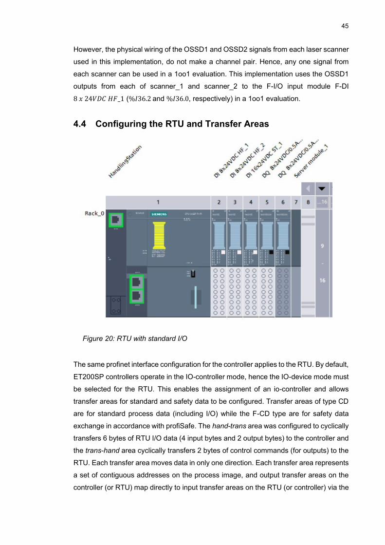
45
However, the physical wiring of the OSSD1 and OSSD2 signals from each laser scanner
used in this implementation, do not make a channel pair. Hence, any one signal from
each scanner can be used in a 1oo1 evaluation. This implementation uses the OSSD1
outputs from each of scanner_1 and scanner_2 to the F-I/O input module F-DI
8 𝑥 24𝑉𝐷𝐶 𝐻𝐹_1 (%𝐼36.2 and %𝐼36.0, respectively) in a 1oo1 evaluation.
4.4 Configuring the RTU and Transfer Areas
Figure 20: RTU with standard I/O
The same profinet interface configuration for the controller applies to the RTU. By default,
ET200SP controllers operate in the IO-controller mode, hence the IO-device mode must
be selected for the RTU. This enables the assignment of an io-controller and allows
transfer areas for standard and safety data to be configured. Transfer areas of type CD
are for standard process data (including I/O) while the F-CD type are for safety data
exchange in accordance with profiSafe. The hand-trans area was configured to cyclically
transfers 6 bytes of RTU I/O data (4 input bytes and 2 output bytes) to the controller and
the trans-hand area cyclically transfers 2 bytes of control commands (for outputs) to the
RTU. Each transfer area moves data in only one direction. Each transfer area represents
a set of contiguous addresses on the process image, and output transfer areas on the
controller (or RTU) map directly to input transfer areas on the RTU (or controller) via the

46
real-time communication link, thereby simplifying access to remote I/O data in both di-
rections. Figure 21 is best viewed in the context of Figure 17 and Appendix B.
Figure 21: Transfer Area Configuration
Safety transfer areas, by default, require 12 bytes of memory for data transfer in each
direction. This allows a fail-safe transfer of a total of 16 Boolean values and 2 integer
values in each direction [64].
4.5 Configuring the Safety Laser Scanners
Configuring a safety zone typically involves marking areas where the beam from the
laser scanner must not be broken by any object or human. In accordance with the phys-
ical setup of the production area, the scanners were setup to monitor the perimeter of
the production area. Any crossing into the monitored while the system is running there-
fore constitutes a breach of safety.
It might be instructive to know that a safety laser scanner is an example of an output-
signal-switching device (OSSD): it trips (turns off) a pair of signals (OSSD1 and OSSD2)
whenever its configured safety zone is breached. Appendix A contains the XML docu-
ments specifying the configuration on each scanner.
4.6 Programming the RTU
The standard governing the programming of PLCs is the IEC 61131-3. It specifies 5
programming languages. For this thesis, the programming languages Structured Text,
and Ladder Diagrams were used in creating all the program units. The RTU programs
are shown in Appendix D.

47
4.6.1 Standard Program
The standard RTU program is a mapping of the local I/O addresses to the transfer area
outputs (hand-trans) and inputs (trans-hand) through ladder diagrams. The controller has
read access to the same addresses via its corresponding transfer area inputs and sends
control commands via the RTU’s transfer area inputs (trans-hand). Figure 21 provides a
simplified view of the data exchange process.
4.6.2 Safety Program
In accordance with the decentralized safety approach proposed in the previous chapter,
the safety program on the RTU is for receiving notification of a safety event when a
foreign object crosses the laser beam. The notification is a Boolean data item in an F-
DB and represents the safety condition in real-time. All moving parts of the handling
station return to their unactuated state as a safety relay disconnects power from the I/O
modules. Since the pneumatic gripper in this station is normally closed, there is no risk
of hazard from a falling workpiece as a result of a safety event. Section 4.7.2 gives a
basic explanation of the certified FBs used.
4.7 Programming the controller
4.7.1 Standard Program
The controller program embodies the logic of the production system. It evaluates data
from both local I/O and RTUs and writes outputs to actuators in accordance with the
implemented logic. For easy distinction between the various types of addresses, 3 tag
tables (or symbol tables) were created: the default tag table (Appendix B.2) contains the
controller’s standard local I/O addresses; safetIO_tags (Appendix B.3) contains ad-
dresses of safety devices in the system, as these are directly connected to the F-I/O
modules; and handling_tagTable (Appendix B.4) contains remote I/O addresses (trans-
fer areas), which are the reflection of the RTU’s local I/O addresses as discussed in
section 4.6.1.
The main program controls the movement of pallets on the conveyors and calls function
blocks (FB) hand1 and hand2, which encapsulate the basic services that the RTU station
offers to the production process. Every pallet is stopped for exactly 2 seconds at the
stopping points (S1 – S6) except at S2 where a pallet carrying a workpiece is held down
until the workpiece is returned from the processing station. hand1 moves a workpiece
from the conveyor side (S2 position in Figure 16) to the processing station side and
hand2 returns the workpiece in the opposite direction, after it must have gone through
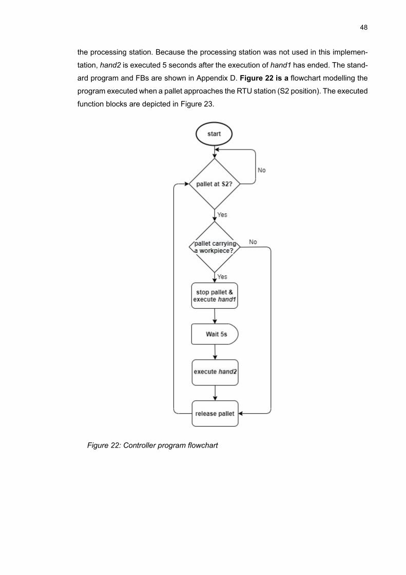
48
the processing station. Because the processing station was not used in this implemen-
tation, hand2 is executed 5 seconds after the execution of hand1 has ended. The stand-
ard program and FBs are shown in Appendix D. Figure 22 is a flowchart modelling the
program executed when a pallet approaches the RTU station (S2 position). The executed
function blocks are depicted in Figure 23.
Figure 22: Controller program flowchart

49
Figure 23: Flow chart depicting hand1 and hand2 FBs

50
4.7.2 Safety Application: SFDOOR
The first step towards creating a safety program is to identify what conditions constitute
a breach of safety in the system and to determine the appropriate safety response. This,
in turn, determines which safety functionalities need to be implemented. TIA Portal pro-
vides a suite of certified industry-standard safety function blocks (F-FBs) that the control
engineer can choose from. Some of these are the emergency stop monitoring, safety
door, two-hand operation, and discrepancy monitoring.
Table 3: List of safety functionalities
Name Safety function
F1 When any of the laser scanners detects an external object crossing the beam,
the conveyor motors must be shut down. (The RTU is notified through the
profiSafe network.)
F2 After safety event F1, the system cannot restart until the user provides an
acknowledgement signal to the controller i.e. no unexpected restart.
This thesis implements a safety door (F1) functionality whose operation is clearly cap-
tured in Figure 24. The laser scanners function exactly like sensors on a safety door for
marking the production area boundaries. The intrusion of a foreign object by breaking
the light beam is equivalent to opening the door, hence constituting a hazard in the pro-
duction area. Consequently, the functional safety system puts the system in a safe state
and production cannot restart unless a user provides some acknowledgement input sig-
nal (F2). An unexpected starting of a machine can be a source of dangerous risk.
The safety signal in the controller is implemented as a Boolean value in an F-DB (Ap-
pendix B.5), which is constantly communicated to the RTU via its own F-DB (Appendix
B.6). Additional standard function blocks (RCVDP and SENDDP) are used for the trans-
mission of this safety data to the RTU through the real-time channel and in accordance
with profiSafe. Each SENDDP block in the controller is a logical counterpart to a RCVDP
block in an io-device: they are essentially endpoints for a unidirectional safety communi-
cation path from one device to the other through the profiSafe network. The safety pro-
gram can be found in Appendix D.2.

51
Figure 13: safety program chart
4.8 Tests and Results
With the implementation described in this chapter, it was possible to monitor the I/O
signals from the handling station PLC (intelligent io-device, RTU) and control it remotely
from the transport station PLC (controller). If a human or other foreign object crosses the
path of the laser beam from either scanner, the system is immediately driven to a safe
state. The system remains in this state until the operator provides an acknowledgement
(from a push button) while no object is in the path of the laser beam. Throughout the
duration of the safe failure, the system ’remembers’ its state just before the failure and
resumes to this state after the acknowlegement signal is provided without requiring any
extra input from the user. This requirement is necessary for minimizing downtime in a
production facility.

52
5. CONCLUSION
The work in this thesis successfully presents a way to implement the control of a mech-
atronic system as a network of intelligent remote terminal units. Furthermore, it highlights
the need for safety in such systems, and presents an implementation that successfully
integrates control logic of the industrial system with its safety logic – a functionally safe
system. It also clearly shows that controlling a production system as a network of physi-
cally separate devices (controllers and RTUs) depends heavily on the underlying network
protocols linking the devices. For an industrial control system, fieldbus protocols are well
established for interconnecting controllers and field devices, although their dominance is
now being challenged by the increasing adoption of industrial ethernet protocols. As a
result, the body of this work also focusses considerably on the unique characteristics
that make these protocols suitable for industrial control functionalities.
Although this implementation uses a centralized control architecture in a network of de-
centralized intelligent devices as a way of keeping up with the topic of this thesis, it is
certainly not the best architecture for a system that is composed of several RTUs, pos-
sibly with hundreds or thousands of I/O addresses. While centralized control may not
present any specific challenges for a small system, controller response times are ad-
versely affected by the large bandwidth requirements of a network of many devices com-
municating cyclically with a central controller. Apart from this, the complexity that results
from centralized control of large networks is making control engineers follow the trend of
decentralized automation and control networks. This complexity can be as a result of the
trouble of debugging a large program on the central controller, for example. Therefore,
a complete implementation of the control of the Festo system (Appendix F.1) as a net-
work of intelligent RTUs can benefit from a decentralized architecture too. A way of im-
plementing this is presented in Appendix E.2. The proposed hierarchical architecture
reduces the bandwidth requirement on every communication link in the network. Further-
more, the many decision-making nodes in a decentralized control architecture represent
a better way to utilize the computing resources distributed throughout network. This the-
sis is essentially a precursor to implementing a full scale profinet-IO system in the Festo
network.
By incorporating monitoring devices at each level of the proposed architecture, this thesis
can serve as a basis for a PLC-based low-cost SCADA system. An example of such a
system is presented in [65]. While selecting the right technology is the first task in any
migration project, the biggest justification for a new system is its superior business value

53
proposition [66]. In the 21st century, environmental concerns have also impacted corpo-
rate objectives and the choice of technology in many industrial systems.

54
REFERENCES
[1] S. Shin, "Trend of Process Automation and Factory Automation", 2006 SICE-
ICASE International Joint Conference, Busan, 2006, pp. 157-160.
[2] P. J. Antsaklis and A. Nerode, "Hybrid Control Systems: An Introductory Discus-sion to the Special Issue", in IEEE Transactions on Automatic Control, vol. 43, no. 4, pp. 457-460, April 1998.
[3] M. Klein and D. Norton, "Increasing the productivity and profitability of machine builders using PC-based control," Proceedings: Electrical Insulation Conference and Electrical Manufacturing and Coil Winding Conference (Cat. No.99CH37035), Cincinnati, OH, USA, 1999, pp. 695-699.
[4] I. Bell, "The future of control [programmable automation controllers]," in Manu-facturing Engineer, vol. 84, no. 4, pp. 36-39, Aug.-Sept. 2005.
[5] B. Chandrasekaran, "AI, knowledge, and the quest for smart systems," in IEEE
Expert, vol. 9, no. 6, pp. 2-5, Dec. 1994.
[6] I. Terzic, A. Zoitl, B. Favre and T. Strasser, "A survey of distributed intelligence in automation in European industry, research and market," 2008 IEEE Interna-tional Conference on Emerging Technologies and Factory Automation, Ham-burg, 2008, pp. 221-228.
[7] J. L. M. Lastra and I. M. Delamer, "Automation 2.0: Current trends in factory au-tomation," 2008 6th IEEE International Conference on Industrial Informatics, Daejeon, 2008, pp. 1321-1323.
[8] G. Wood, "State of play [fieldbus technology]," in IEE Review, vol. 46, no. 4, pp.
26-28, July 2000, doi: 10.1049/ir:20000404.
[9] Research and Markets, “Global intelligent Remote terminal Unit Market 2020 –
2024”. Accessed 23 June 2020 < https://www.researchandmarkets.com/re-
ports/5011366/global-intelligent-remote-terminal-unit-market#rela4-4436080 >
[10] R.H. Bishop in “Mechatronics: An Introduction”. USA: Taylor and Francis Group,
2006, p. viii.
[11] Q. Bi and J. Li, "Application of Intelligent Control in Mechatronics System," 2019
IEEE 7th International Conference on Computer Science and Network Technol-
ogy (ICCSNT), Dalian, China, 2019, pp. 272-276, doi: 10.1109/IC-
CSNT47585.2019.8962416.
[12] I. Harjunkoski, “Integration of Scheduling and ISA-95.” in Computer Aided Chemi-
cal Engineering, Vol. 33, 2014, p. 427-432, doi: 10.1016/B978-0-444-63456-
6.50072-7.

55
[13] L. A. Bryan and E. A. Bryan, “Programmable Controllers: Theory and Implemen-
tation”, 2nd edition, USA, 1997.
[14] B. R. Mehta and Y. J. Reddy, “Industrial Process Automation Systems: Design
and Implementation”, UK: Elsevier; 2015, p. 40.
[15] M. Zhang et al., "Towards Automated Safety Vetting of PLC Code in Real-World
Plants," 2019 IEEE Symposium on Security and Privacy (SP), San Francisco,
CA, USA, 2019, pp. 522-538, doi: 10.1109/SP.2019.00034.
[16] (Siemens) Industry Online Support, Where and when do you need peripheral ad-
dressing? Accessed 17 May 2020 <https://support.industry.siemens.com/cs/doc-
ument/18325417/where-and-when-do-you-need-peripheral-addressing-
?dti=0&lc=en-WW>
[17] K. -H. John and M. Tiegelkamp, “IEC 61131-3: Programming Industrial Automa-
tion Systems”. 2nd Ed. Heidelberg, Dordretch, London, New York: Springer;
2010.
[18] IEC 61131 SER, Programmable Controllers – ALL PARTS, Accessed 17 May
2020 <https://webstore.iec.ch/publication/62427#additionalinfo>
[19] International Electrotechnical Commission, Programmable Controllers – Part 6:
Functional Safety, Europe, 2012.
[20] K. Rástočný and J. Ždánsky, "Specificities of safety PLC based implementation
of the safety functions," 2012 International Conference on Applied Electronics,
Pilsen, 2012, pp. 229-232.
[21] H. Kanamaru, T. Mogi and N. Aoyama, "Functional safety application using
safety PLC," SICE Annual Conference 2007, Takamatsu, 2007, pp. 2489-2492,
doi: 10.1109/SICE.2007.4421408.
[22] Z. Du, G. Cheng, M. Wang, R. Sun and K. Liu, "Research on Safety Program-mable Controller Based on Dual-CPU Architecture," 2019 IEEE 3rd Information Technology, Networking, Electronic and Automation Control Conference (IT-NEC), Chengdu, China, 2019, pp. 2034-2038, doi: 10.1109/IT-NEC.2019.8729401.
[23] Siemens AG, Fault-tolerant Process Control Systems (V8.1) Function Manual
A5E34878832-AA, 11/2014.
[24] B. Galloway and G. P. Hancke, "Introduction to Industrial Control Networks," in
IEEE Communications Surveys & Tutorials, vol. 15, no. 2, pp. 860-880, Second
Quarter 2013, doi: 10.1109/SURV.2012.071812.00124.
[25] D.-S. Kim and H. Tran-Dang, “Industrial Sensors and Controls in Communication
Networks”, Switzerland, 2019, p. 11. doi: 10.1007/978-3-030-04927-0

56
[26] M. Roa, W. Cantrell, D. Cartes and M. Nelson, "Requirements for deterministic control systems," 2011 IEEE Electric Ship Technologies Symposium, Alexan-dria, VA, 2011, pp. 439-445, doi: 10.1109/ESTS.2011.5770912.
[27] AutomationWorld, "Industrial Ethernet and wireless growing steadily – first year of
decline for fieldbuses in terms of new nodes”, Accessed 26 May 2020
<https://www.automationworld.com/home/news/13319803/industrial-ethernet-
and-wireless-growing-steadily-first-year-of-decline-for-fieldbuses-in-terms-of-new-
nodes>
[28] H. Hadeli, R. Schierholz, M. Braendle and C. Tuduce, "Leveraging determinism in industrial control systems for advanced anomaly detection and reliable secu-rity configuration," 2009 IEEE Conference on Emerging Technologies & Factory Automation, Mallorca, 2009, pp. 1-8, doi: 10.1109/ETFA.2009.5347134.
[29] D. Caro, “Automation Network Selection: A Reference Manual” 3rd Ed., ISA,
Chapter 3, 2009.
[30] S. Cavalieri, A. Di Stefano and O. Mirabella, "Centralized versus distributed pro-tocols for FieldBus applications," Proceedings of IECON '95 - 21st Annual Con-ference on IEEE Industrial Electronics, Orlando, FL, USA, 1995, pp. 1580-1585 vol.2, doi: 10.1109/IECON.1995.484186.
[31] J. -. Thomesse, "Fieldbus Technology and Industrial Automation," 2005 IEEE Conference on Emerging Technologies and Factory Automation, Catania, 2005, pp. 651-653, doi: 10.1109/ETFA.2005.1612584.
[32] G. Wood, "State of play [fieldbus technology]," in IEE Review, vol. 46, no. 4, pp. 26-28, July 2000, doi: 10.1049/ir:20000404.
[33] M. Felser and T. Sauter, "The fieldbus war: history or short break between bat-tles?" 4th IEEE International Workshop on Factory Communication Systems, Vasteras, Sweden, 2002, pp. 73-80.
[34] HMS Industrial Networks, “Industrial networks market Shares 2019 according to
HMS”, Accessed 7 June 2020. <https://www.hms-networks.com/news-and-in-
sights/news-from-hms/2019/05/07/industrial-network-market-shares-2019-ac-
cording-to-hms>
[35] C. Siegfried, R. Constantin and S. Stancescu, "Evaluation of protocol for indus-trial informatics systems," 2010 8th International Conference on Communica-tions, Bucharest, 2010, pp. 293-296, doi: 10.1109/ICCOMM.2010.5509109.
[36] C. Polsonetti, “Industrial Ethernet Protocol Wars: Fieldbus Revisited” in “Fieldbus
Technology (Industrial Network Standards for Real-Time Distributed Control)”,
Verlag Berlin Hiedelberg New York 2003, pp. 39-56.
[37] IEEE, “Time-Sensitive Networking (TSN) Task Group”, Accessed 7 June 2020.
<https://1.ieee802.org/tsn/>
[38] Cisco Systems White Paper, “Time-Sensitive Networking: A Technical Introduc-
tion”. 2017

57
[39] J. Feld, "PROFINET - scalable factory communication for all applications," IEEE International Workshop on Factory Communication Systems, 2004. Proceed-ings., Vienna, 2004, pp. 33-38, doi: 10.1109/WFCS.2004.1377673.
[40] A. Poschraann and P. Neumann, "Architecture and model of Profinet IO," 2004 IEEE Africon. 7th Africon Conference in Africa (IEEE Cat. No.04CH37590), Gaborone, 2004, pp. 1213-1218 Vol.2, doi: 10.1109/AFRICON.2004.1406884.
[41] PI North America, “PROFINET for Network Geeks (and those who want to be)”,
Doc 10-104 v2.
[42] PI North America, “Switched Ethernet Networks for Profinet Determinism”, Ac-
cessed 11 June 2020. <https://us.profinet.com/switched-ethernet-networks-
profinet-determinism/>
[43] Profinet International, “Tech Tip: Profinet on Switched Networks”, Accessed 11
June 2020. <https://profinews.com/2016/11/tech-tip-profinet-on-switched-net-
works/>
[44] M. Yang and G. Li, "Analysis of PROFINET IO Communication Protocol," 2014
Fourth International Conference on Instrumentation and Measurement, Com-
puter, Communication and Control, Harbin, 2014, pp. 945-949.
[45] R. Pigan and M. Metter, “Automating with PROFINET: Industrial Communication
Based on Industrial Ethernet”, 2019, p. 48.
[46] Profibus Trade Organization, “PROFINET Technology and Application”, Ger-
many. USA. April 2006, p. 4.
[47] Profinet University, “Isochronous Real-Time (IRT) Communication”, Accessed 12
June 2020. <https://profinetuniversity.com/profinet-basics/isochronous-real-time-
irt-communication/>
[48] Profibus and Profinet International, “PROFIsafe System Description (Technology
and Application)”, Germany, 2016.
[49] ETSI.org, “About ETSI”, Accessed 5 April 2020 <https://www.etsi.org/about>
[50] ABB, “The safety handbook Experience-Systems-Products”, Accessed 23 June
2020 <ftp://bs.solar.eu/usr/TPS/Industrie/ABBAC500/ABB_Safety_Hand-
book.pdf>
[51] D. J. Smith and K.G.L. Simpson, “Safety-critical systems handbook”, Elsevier,
2011, doi: 10.1016/B978-0-08-096781-3.10001-X.
[52] CENELEQ, “FAQs”, Accessed 5 April 2020 <https://www.cenelec.eu/faq/faq_en-
try.htm#Q6>

58
[53] S. Robinson, “SIL or PL? What is the difference”, Accessed 22 April 2020
<https://www.lcautomation.com/wb_docu-
ments/pilz/sil%20or%20pl,%20what%20is%20the%20difference.pdf>
[54] Dean, S. (1999). IEC 61508 — Understanding Functional Safety Assessment.
Measurement and Control, 32(7), 201–204.
https://doi.org/10.1177/002029409903200703
[55] GM International, “What is the Safety Life Cycle?”, Accessed 5 April 2020,
<https://news.gminternational.com/what-is-safety-life-cycle>
[56] ISO.org, “ISO 12100:2010 safety of machinery — General principles for design — Risk
assessment and risk evaluation” Accessed 25 April 2020 <https://www.iso.org/stand-
ard/51528.html>
[57] D. J. Smith and K.G.L. Simpson, “Safety-critical systems handbook”, Elsevier,
2011, doi: 10.1016/B978-0-08-096781-3.10001-X.
[58] HSE, “ALARP at a glance”, Accessed 25 March 2020,
<https://www.hse.gov.uk/risk/theory/alarpglance.htm>
[59] A. G. Foord and C. R. Howard, "Energise or De-Energise to Trip?" 2007 2nd In-stitution of Engineering and Technology International Conference on System Safety, London, 2007, pp. 147-152, doi: 10.1049/cp:20070456.
[60] Siemens AG, “I-Device Function in Standard PN Communication”, Available at https://support.industry.siemens.com/cs/ww/en/view/109478798
[61] Siemens AG, “Data Record Communication via I-device”, V2.0, 07/2019
[62] Siemens AG, “SIMATIC Industrial Software (SIMATIC Safety – Configuring and
Programming)”, October 2018 ed.
[63] 65 Siemens AG, “ET200SP Digital input module F-DI 8 x 24 VDC HF (6ES7136-
6BA00-0CA0) Manual”, Chapter 4, 07/2013.
[64] 66 Siemens AG, “Safety-Related IO Controller-I-device Communication”, V2.2
08/2019, <https://support.industry.siemens.com/cs/ww/en/view/109478798>
[65] Y. Musa et al., "Low-Cost Remote Supervisory Control System for an Industrial Process using Profibus and Profinet," 2019 SoutheastCon, Huntsville, AL, USA, 2019, pp. 1-4, doi: 10.1109/SoutheastCon42311.2019.9020630.
[66] Honeywell Process Solutions, “Business Justification: Why Migrate Legacy Con-trol Systems?” Available at <https://www.honeywellprocess.com/library/market-ing/whitepapers/White-Paper-Why-Migrate-Legacy-Control-Systems-Business-Justification.pdf>

59
APPENDIX A: RTU CONFIGURATION

60
APPENDIX B: SYMBOL TABLES
B.1 RTU symbol table

61
B.2 Controller symbol table (standard I/O)

62
B.3 Controller symbol table (safety I/O)

63
B.4 Controller symbol table (remote I/O & bit memory)

64
B.5 Controller F-DB (safety data block)
B.6 RTU F-DB (safety data block)

65
APPENDIX C: RTU PROGRAM
C.1 Standard Program

66

67
C.2 Safety Program

68

69
APPENDIX D: CONTROLLER PROGRAM
D.1 Standard Program

70
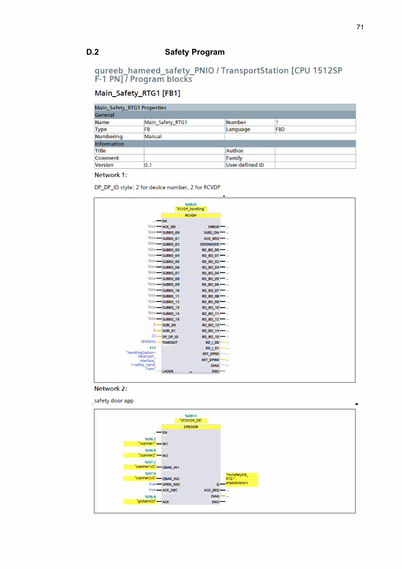
71
D.2 Safety Program

72

73
D.3 hand1 (Function Block)

74

75

76
D.4 hand2 (Function Block)

77

78

79
APPENDIX E: THE FESTO NETWORK
E.1 THE PHYSICAL LAYOUT

80
E.2 PROPOSED DECENTRALIZED CONTROL ARCHITECTURE WITH PNIO