Embed Size (px)
Citation preview
Chapter 15
AC Fundamentals
2
Alternating Current• Voltages of ac sources alternate in
polarity and vary in magnitude
• Voltages produce currents that vary in magnitude and alternate in direction

3
Alternating Current• A sinusoidal ac waveform starts at zero
– Increases to a positive maximum– Decreases to zero– Changes polarity– Increases to a negative maximum– Returns to zero
• Variation is called a cycle
4
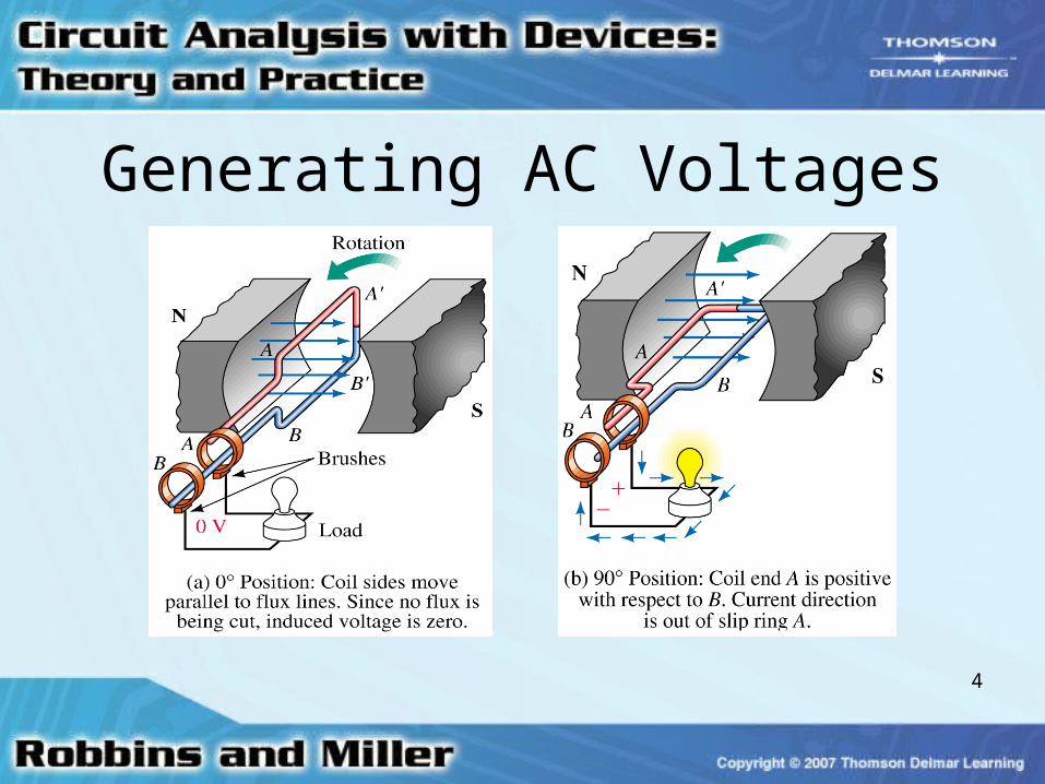
Generating AC Voltages
5
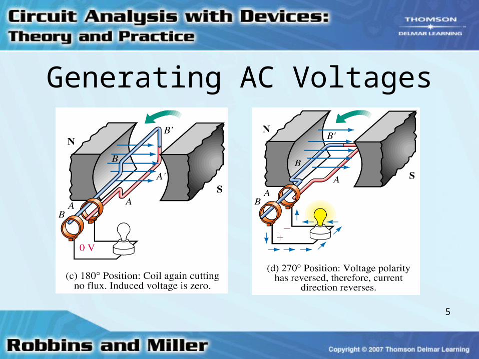
Generating AC Voltages
6
AC Voltage-Current Conventions • Assign a reference polarity for source
• When voltage has a positive value– Its polarity is same as reference polarity
• When voltage is negative– Its polarity is opposite that of the reference
polarity

7
AC Voltage-Current Conventions • Assign a reference direction for current
that leaves source at positive reference polarity
• When current has a positive value– Its actual direction is same as current
reference arrow

8
AC Voltage-Current Conventions • When current is negative
– Its actual direction is opposite that of current reference arrow

9
Frequency• Number of cycles per second of a
waveform – Frequency– Denoted by f
• Unit of frequency is hertz (Hz)
• 1 Hz = 1 cycle per second

10
Period• Period of a waveform
– Time it takes to complete one cycle
• Time is measured in seconds
• The period is the reciprocal of frequency– T = 1/f
11
Amplitude and Peak-to-Peak Value
• Amplitude of a sine wave – Distance from its average to its peak
• We use Em for amplitude• Peak-to-peak voltage
– Measured between minimum and maximum peaks
• We use Epp or Vpp

12
Peak Value• Peak value of an ac voltage or current
– Maximum value with respect to zero
• If a sine wave is superimposed on a dc value– Peak value of combined wave is sum of dc
voltage and peak value of ac waveform amplitude
13
The Basic Sine Wave Equation• Voltage produced by a generator is
– e = Em sin
• Em is maximum (peak) voltage
is instantaneous angular position of rotating coil of the generator
14
The Basic Sine Wave Equation• Voltage at angular position of sine wave
generator– May be found by multiplying Em times the sine
of angle at that position

15
Angular Velocity• Rate at which the generator coil rotates
with respect to time, (Greek letter omega)

16
Angular Velocity• Units for are revolutions/second,
degrees/sec, or radians/sec.
tt

17
Radian Measure is usually expressed in radians/second
• 2 radians = 360°
• To convert from degrees to radians, multiply by /180

18
Radian Measure• To convert from radians to degrees,
multiply by 180/• When using a calculator
– Be sure it is set to radian mode when working with angles measured in radians

19
Relationship between ,T, and f• One cycle of a sine wave may be
represented by = 2 rads or t = T sec
fT
T
t
2
2
2
20
Voltages and Currents as Functions of Time
• Since = t, the equation e = Em sin becomes e(t) = Em sin t
• Also, v(t) = Vm sin t and i(t) = Im sin t
21
Voltages and Currents as Functions of Time
• Equations used to compute voltages and currents at any instant of time
• Referred to as instantaneous voltage or current

22
Voltages and Currents with Phase Shifts
• If a sine wave does not pass through zero at t = 0, it has a phase shift
• For a waveform shifted left– v = Vm sin(t + )
• For a waveform shifted right– v = Vm sin(t - )

23
Phasors• Rotating vectors whose projection onto a
vertical or horizontal axis can be used to represent sinusoidally varying quantities

24
Phasors• A sinusoidal waveform
– Produced by plotting vertical projection of a phasor that rotates in the counterclockwise direction at a constant angular velocity

25
Phasors• Phasors apply only to sinusoidally
varying waveforms

26
Shifted Sine Waves
• Phasors used to represent shifted waveforms
• Angle is position of phasor at t = 0 seconds

27
Phase Difference• Phase difference is angular displacement
between waveforms of same frequency
• If angular displacement is 0°– Waveforms are in phase
28
Phase Difference• If angular displacement is not 0o, they are
out of phase by amount of displacement
29
Phase Difference• If v1 = 5 sin(100t) and v2 = 3 sin(100t -
30°), v1 leads v2 by 30°
• May be determined by drawing two waves as phasors – Look to see which one is ahead of the other
as they rotate in a counterclockwise direction

30
Average Value• To find an average value of a waveform
– Divide area under waveform by length of its base
• Areas above axis are positive, areas below axis are negative
31
Average Value• Average values also called dc values
– dc meters indicate average values rather than instantaneous values

32
Sine Wave Averages• Average value of a sine wave over a
complete cycle is zero
• Average over a half cycle is not zero

33
Sine Wave Averages• Rectified full-wave average is 0.637 times
the maximum value
• Rectified half-wave average is 0.318 times the maximum value

34
Effective Values• Effective value or RMS value of an ac
waveform is an equivalent dc value– It tells how many volts or amps of dc that an ac
waveform supplies in terms of its ability to produce the same average power

35
Effective Values• In North America, house voltage is 120
Vac. – Voltage is capable of producing the same
average power as a 120 V battery
36
Effective Values• To determine effective power
– Set Power(dc) = Power(ac)
Pdc = pac
I2R = i2R where i = Im sin t• By applying a trigonometric identity
– Able to solve for I in terms of Im

37
Effective Values• Ieff = .707Im
• Veff = .707Vm
• Effective value is also known as the RMS value