Embed Size (px)
Citation preview
TM 5-814-3/AFM 88-11, Volume III
15-1
CHAPTER 15ADVANCED WASTEWATER TREATMENT
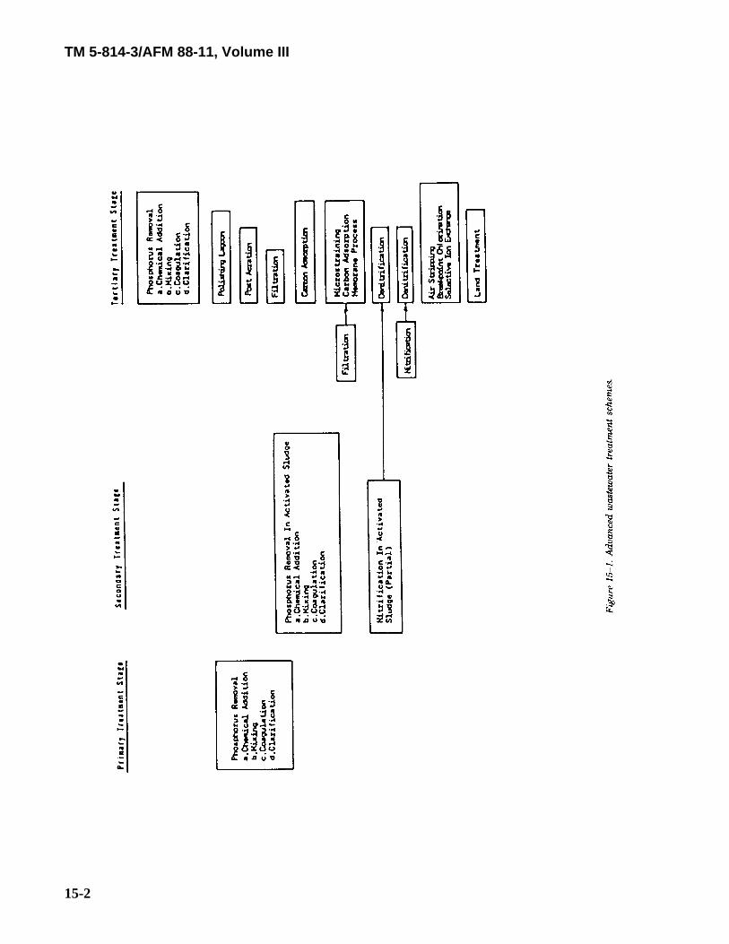
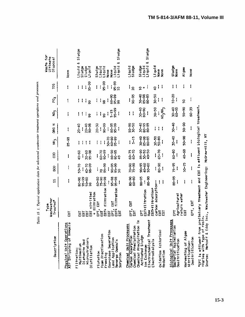
15-1. Sequence of processes.A number of different unit operations are used in varius configurations to make up an advanced wastewatertreatment system. The particular situation determines the most applicable process design. The generalsequence of unit operations typically used in advanced treatment is presented in schematic form in figure 15-1. Table 15-1 presents the applications, advantages, and disadvantages of various advanced wastewatertreatment processes arranged in such a way as to provide a ready comparison between alternative treatmentprocesses. The applications listed are those for which the process is normally selected. However, manyprocesses, although selected on the basis of their effectiveness in removal of a particular pollutant, obtainadditional benefits in the control of other waste characteristics.
TM 5-814-3/AFM 88-11, Volume III
15-2
TM 5-814-3/AFM 88-11, Volume III
15-3
TM 5-814-3/AFM 88-11, Volume III
15-4
15-2. Polishing ponds.Wastewater treatment ponds may be used as a practical and economical method for upgrading existingsecondary treatment facilities to obtain improved organic and suspended solids removal. Both aerobic andaerobic-anaerobic ponds can be used for this purpose. Ponds used for polishing purposes are subject to thesame operating characteristics as those used for primary or secondary treatment, and the same precautionarydesign considerations must be applied. The design information and criteria presented in chapter 14 areapplicable to design of polishing ponds. (See also Culp and Culp, 1971.)
15-3. Post-aeration.This can be accomplished by either diffused, cascade, U-tube or mechanical aeration. Diffused aeration iscarried out in tanks 9 to 15 feet deep and 10 to 50 feet wide (depth-to-width ratio is maintained at less than2), with detention time of about 20 minutes. The maximum air requirement is approximately 0.15 cubic feetper gallon of wastewater treated. Mechanically aerated basins are 8 feet deep and require 15 to 50 square feetper aerator. Surface aeration is the most efficient mechanical aeration in terms of required horsepower (0.1horsepower per 1,000 gallons of effluent). The drop required for cascade aeration in a stepped-weir structureor in a rapidly sloping channel filled with large rocks or concrete blocks will depend on the desired oxygenuptake: 2 feet of drop will be provided for each milligram per liter of dissolved oxygen increase required.
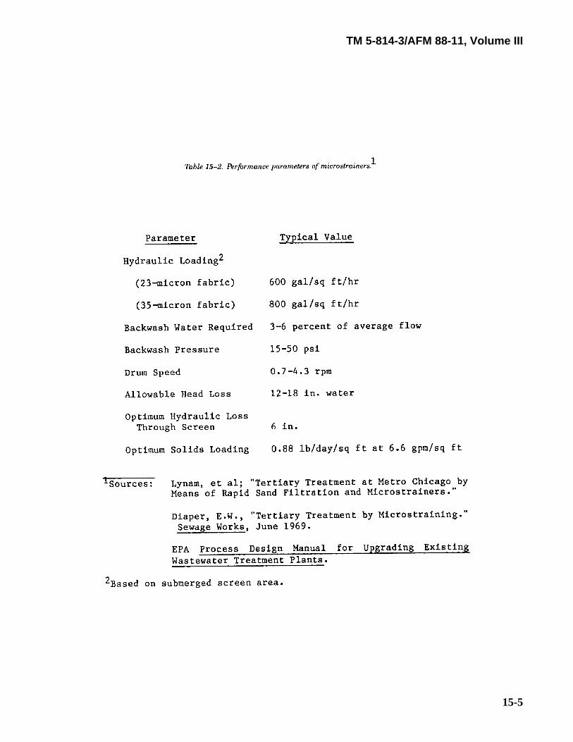
15-4. Microstraining.a. Description of process. A microstrainer consists of a rotating drum supporting a very fine, stainless
steel or plastic screen. Wastewater is fed into the inside of the drum and filters radially outward through thescreen, with the mat of solids accumulating on the screen inside the drum. The solids are flushed into aremoval trough at the top of the drum by a pressurized backwash system. From this trough, the solids arereturned to the head of the system. Process effluent wastewater can be used for the backwash. Table 15-2provides performance data for several microscreen installations.
TM 5-814-3/AFM 88-11, Volume III
15-5
TM 5-814-3/AFM 88-11, Volume III
15-6
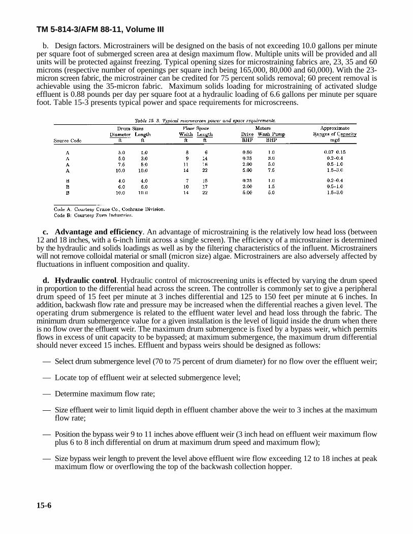
b. Design factors. Microstrainers will be designed on the basis of not exceeding 10.0 gallons per minuteper square foot of submerged screen area at design maximum flow. Multiple units will be provided and allunits will be protected against freezing. Typical opening sizes for microstraining fabrics are, 23, 35 and 60microns (respective number of openings per square inch being 165,000, 80,000 and 60,000). With the 23-micron screen fabric, the microstrainer can be credited for 75 percent solids removal; 60 precent removal isachievable using the 35-micron fabric. Maximum solids loading for microstraining of activated sludgeeffluent is 0.88 pounds per day per square foot at a hydraulic loading of 6.6 gallons per minute per squarefoot. Table 15-3 presents typical power and space requirements for microscreens.
c. Advantage and efficiency. An advantage of microstraining is the relatively low head loss (between12 and 18 inches, with a 6-inch limit across a single screen). The efficiency of a microstrainer is determinedby the hydraulic and solids loadings as well as by the filtering characteristics of the influent. Microstrainerswill not remove colloidal material or small (micron size) algae. Microstrainers are also adversely affected byfluctuations in influent composition and quality.
d. Hydraulic control. Hydraulic control of microscreening units is effected by varying the drum speedin proportion to the differential head across the screen. The controller is commonly set to give a peripheraldrum speed of 15 feet per minute at 3 inches differential and 125 to 150 feet per minute at 6 inches. Inaddition, backwash flow rate and pressure may be increased when the differential reaches a given level. Theoperating drum submergence is related to the effluent water level and head loss through the fabric. Theminimum drum submergence value for a given installation is the level of liquid inside the drum when thereis no flow over the effluent weir. The maximum drum submergence is fixed by a bypass weir, which permitsflows in excess of unit capacity to be bypassed; at maximum submergence, the maximum drum differentialshould never exceed 15 inches. Effluent and bypass weirs should be designed as follows:
— Select drum submergence level (70 to 75 percent of drum diameter) for no flow over the effluent weir;
— Locate top of effluent weir at selected submergence level;
— Determine maximum flow rate;
— Size effluent weir to limit liquid depth in effluent chamber above the weir to 3 inches at the maximumflow rate;
— Position the bypass weir 9 to 11 inches above effluent weir (3 inch head on effluent weir maximum flowplus 6 to 8 inch differential on drum at maximum drum speed and maximum flow);
— Size bypass weir length to prevent the level above effluent wire flow exceeding 12 to 18 inches at peakmaximum flow or overflowing the top of the backwash collection hopper.
TM 5-814-3/AFM 88-11, Volume III
15-7
e. Backwashing. Backwash jets are directed against the outside of the microscreen drum as it passes thehighest point in its rotation. About half the flow penetrates the fabric, dislodging the mat of solids formedon the inside. A hopper inside the drum receives the flushed-off solids. The hopper is positioned tocompensate for the trajectory that the solids follow at normal drum peripheral velocities. Microscreen effluentis usually used for Backwashing. Straining is required to avoid clogging of backwash nozzles. The inlinestrainers used for this purpose will require periodic cleaning; the frequency of cleaning will be determinedby the quality of the backwash water.
(1) Sytems. The backwash system used by Zurn employs two header pipes; one operates continuouslyat 20 pounds per square inch, while the other operates at 40-55 pounds per square inch. Under normaloperating conditions, these jets operate at 35 pounds per square inch. Once a day they are operated at 50pounds per square inch for ½ hour to keep the jets free of slime buildup. Should this procedure fail to keepthe jets clean, the pressure is raised to 55 pounds per square inch. At this pressure the spring-loaded jetmouth widens to allow for more effective cleaning.
(2) High pressure. Backwash pressure can be increased to compensate for heavy solids loadings whichrequire higher pressure for thorough cleaning. The superiority of the higher-pressure system is manifestedby the following:
(a) Operation at 50 pounds per square inch, as opposed to 15 pounds per square inch, increases theprocess flow capacity 30 percent.
(b) Suspended solids concentration in the backwash can increase from 260 milligrams per liter at 15pounds per square inch to 425 milligrams per liter at 50 pounds per square inch.
(c) Water consumption of the jets as a percent of process effluent decreases from 5 percent at 15pounds per square inch to 2 percent at 50 pounds per square inch. In general, backwash systems are operatedat as low a pressure as possible consistent with successful cleaning. High-pressure operation incurs addedsystem maintenance, particularly jet replacement, and is used only as needed.
f. Supplemental cleaning. Over a period of time, screen fabrics may become clogged with algal andslime growths, oil, and grease. To prevent clogging, cleaning methods in addition to Backwashing arenecessary.
(1) Ultraviolet lamps. Th reduce clogging from algal and slime growth, the use of ultraviolet lampsplaced in close proximity to the screening fabric and monthly removal of units from service to permit screencleaning with a mild chlorine solution is recommended. While most literature sources say ultraviolet lampsare of value, one authority feels these lamps are uneconomical because they require frequent replacement.Zurn Industries claims that, because their screening fabric is completely bonded to the supporting material,crevices where algae become lodged are eliminated and Backwashing alone is sufficient to remove algal andassociated slime growths.
(2) Hot water. Where oil and grease are present, hot water and/or steam treatment can be used toremove these materials from the microscreens. Plastic screens with grease problems are cleaned monthly withhot water at 1200 Fahrenheit to prevent damage to the screen material. Downtime for cleaning may be upto 8 hours.
g. Operation. In starting a microscreening unit, care should be taken to limit differential water levelsacross the fabric to normal design ranges of 2 to 3 inches. For example, while the drum is being filled, itshould be kept rotating and the backwash water should be turned on as soon as possible. This is done to limitthe formation of excessive differential heads across the screen which would stress the fabric during tank fill-up. Leaving the drum standing in dirty water should be avoided because suspended matter on the insidescreen face which is above the water level may dry and prove difficult to remove. For this reason, introducingunscreened waters, such as plant overloads, into the microscreen effluent compartment should also beavoided. If the unit is to be left standing for any length of time, the tank should be drained and the fabriccleaned to prevent clogging from drying solids.
TM 5-814-3/AFM 88-11, Volume III
15-8
15-5. Filtration.a. Basic design parameters. The basic parameters to consider are the following:
— Type and size of filter media;
— Depth of filter;
— Rate, duration and timing of backwash;
— Filter run duration;
— Filtration rate; and
— Type of chemical pretreatment dosage requirement.
b. Coarse-media filtration.
(1) General design consideration. Filter media size will influence filter performance; smaller mediawill achieve better suspended solids removal, but will involve increased pressure drop and head loss buildup.Therefore, a balance between removal efficiency and hydraulic loading rate must be attained. For sewageapplications, coarser media, higher flow rates and longer filter runs will be used. Chemical treatment of thefeed water may be necessary to improve effluent quality.
(2) Media sizes and filtration rate. Coarse media particles must have an effective size ofapproximately 1.3 millimeters with a uniformity coefficient of approximately 1. Sand or anthracite coal maybe used, with coal giving a poorer solids removal but producing less pressure drop. Refer to the EPA ProcessDesign Manual for Suspended Solids Removal for additional information regarding media specification.The design application rate for coarse-media filters will be 5 gallons per minute per square foot at designmaximum flow.
(3) Effectivenness. Single-media, coarse sand filters will be credited with 60 percent removal ofsuspended solids when the sand media size is no greater than 1.0 millimeters and the flow rate is no greaterthan 4 gallons per minute per square foot. Biochemical oxygen demand removal efficiencies will be dependenton the biochemical oxygen demand fraction of the suspended solids that is removed since dissolved organicmaterials generally pass through the filter.
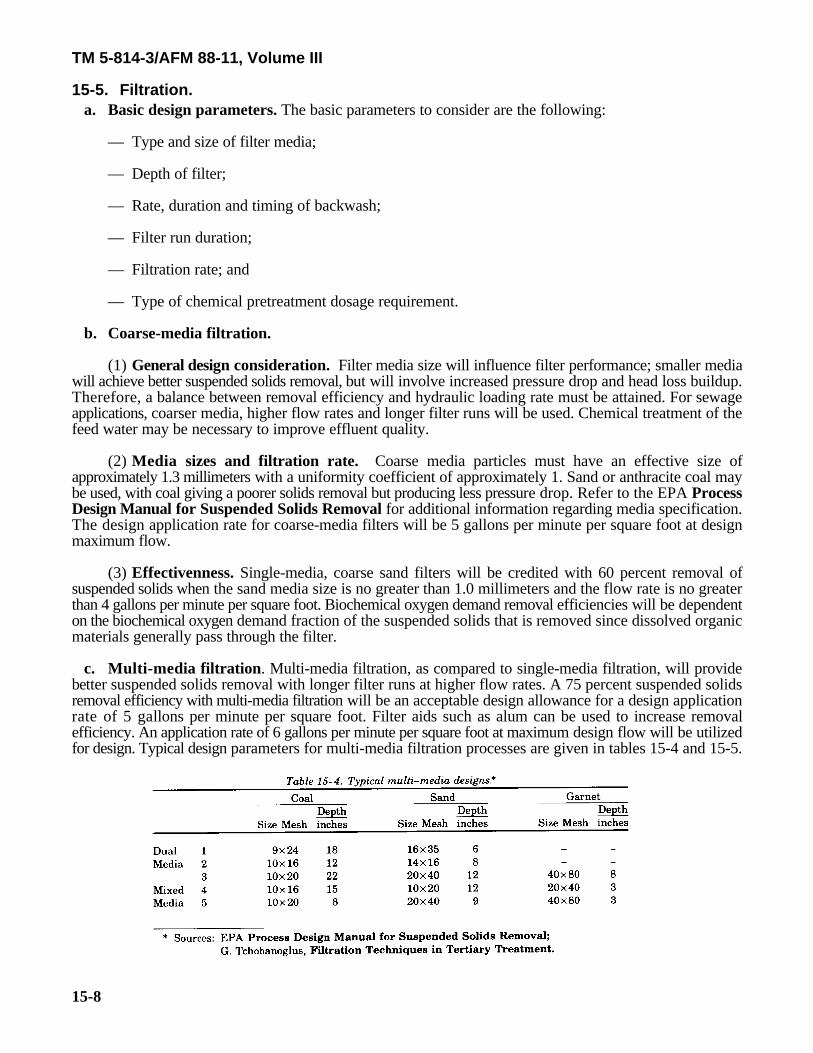
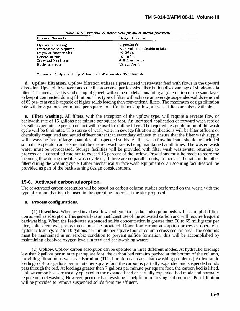
c. Multi-media filtration. Multi-media filtration, as compared to single-media filtration, will providebetter suspended solids removal with longer filter runs at higher flow rates. A 75 percent suspended solidsremoval efficiency with multi-media filtration will be an acceptable design allowance for a design applicationrate of 5 gallons per minute per square foot. Filter aids such as alum can be used to increase removalefficiency. An application rate of 6 gallons per minute per square foot at maximum design flow will be utilizedfor design. Typical design parameters for multi-media filtration processes are given in tables 15-4 and 15-5.
TM 5-814-3/AFM 88-11, Volume III
15-9
d. Upflow filtration. Upflow filtration utilizes a pressurized wastewater feed with flows in the upwarddirec-tion. Upward flow overcomes the fine-to-coarse particle-size distribution disadvantage of single-mediafilters. The media used is sand on top of gravel, with some models containing a grate on top of the sand layerto keep it compacted during filtration. This type of filter will achieve an average suspended-solids removalof 85 per- cent and is capable of higher solids loading than conventional filters. The maximum design filtrationrate will be 8 gallons per minute per square foot. Continuous upflow, air wash filters are also available.
e. Filter washing. All filters, with the exception of the upflow type, will require a reverse flow orbackwash rate of 15 gallons per minute per square foot. An increased application or forward wash rate of25 gallons per minute per square foot will be used for upflow filters. The required design duration of the washcycle will be 8 minutes. The source of wash water in sewage filtration applications will be filter effluent orchemically coagulated and settled effluent rather than secondary effluent to ensure that the filter wash supplywill always be free of large quantities of suspended solids. A filter wash flow indicator should be includedso that the operator can be sure that the desired wash rate is being maintained at all times. The wasted washwater must be reprocessed. Storage facilities will be provided with filter wash wastewater returning toprocess at a controlled rate not to exceed 15 percent of the inflow. Provisions must be made to store theincoming flow during the filter wash cycle or, if there are no parallel units, to increase the rate on the otherfilters during the washing cycle. Either mechanical surface wash equipment or air scouring facilities will beprovided as part of the backwashing design considerations.
15-6. Activated carbon adsorption.Use of activated carbon adsorption will be based on carbon column studies performed on the waste with thetype of carbon that is to be used in the operating process at the site proposed.
a. Process configurations.
(1) Downflow. When used in a downflow configuration, carbon adsorption beds will accomplish filtra-tion as well as adsorption. This generally is an inefficient use of the activated carbon and will require frequentbackwashing. When the feedwater suspended solids concentration is greater than 50 to 65 milligrams perliter, solids removal pretreatment must be provided. Downflow carbon adsorption processes operate athydraulic loadings of 2 to 10 gallons per minute per square foot of column cross-section area. The columnsmust be maintained in an aerobic condition to prevent sulfide formation; this will be accomplished bymaintaining dissolved oxygen levels in feed and backwashing waters.
(2) Upflow. Upflow carbon adsorption can be operated in three different modes. At hydraulic loadingsless than 2 gallons per minute per square foot, the carbon bed remains packed at the bottom of the column,providing filtration as well as adsorption. (This filtration can cause backwashing problems.) At hydraulicloadings of 4 to 7 gallons per minute per square foot, the carbon is partially expanded and suspended solidspass through the bed. At loadings greater than 7 gallons per minute per square foot, the carbon bed is lifted.Upflow carbon beds are usually operated in the expanded-bed or partially expanded-bed mode and normallyrequire no backwashing. However, periodic backwashing is helpful in removing carbon fines. Post-filtrationwill be provided to remove suspended solids from the effluent.
TM 5-814-3/AFM 88-11, Volume III
15-10
(3) Pulsed bed. A "pulsed bed" is defined as an upflow carbon adsorption system where a layer ofexhausted carbon is withdrawn from the bottom of the carbon bed, with a regenerated layer being added tothe top of the bed. This technique approximates countercurrent operation and is a nearly-continuous process.
(4) Gravity and pressurized flow. Gravity-flow systems have the advantage of eliminating the needfor pumps and pressure vessels. The restricting factor in gravity flow is head loss. For this reason,pretreatment for suspended solids removal is required. Gravity-flow systems can either downflow or upflow.The upflow, expanded-bed configuration will facilitate maintenance of a constant head loss. Pressurized-flowsystems will offer more flexibility in process design by operating at higher flow rates and over wider rangesof pressure drop.
(5) Series and parallel arrangement. Carbon contacting beds can be arranged as single stages,independently operated; or as multi-stages, either in series or in parallel. Series configurations achieve morecomplete organic removal and will be used when carbon adsorption is required to remove 90 percent of thetotal plant organics. Economic studies indicate that two-stage series operation is least expensive in terms ofoperating costs. For lower levels of treatment, single-stage, parallel contactors staggered in their status ofoperation or degree of exhaustion can produce the desired product by blending of individual effluent.
(6) Regeneration. Activated carbon is regenerated in a step heating process; refer to the EPA ProcessDesign Manual for Carbon Adsorption for design details. Carbon regeneration systems include preliminarydewatering of the carbon slurry to a moisture content of 40 to 50 percent, heating in a multiple-hearth furnaceto 1,500-1,700 degrees Fahrenheit, quenching of regenerated carbon, and recycle to contactors. Theregeneration process requires 3,200 British thermal units for burning off the impurities and 1 pound steamper pound of regenerated carbon. Air pollution control equipment is required, usually an afterburner and awet scrubber or bag filter.
(7) Carbon transport. The carbon is usually transported within the system as a slurry at velocitiesbetween 2.5 and 10 feet per second. Lower velocities make the system vulnerable to solids deposition andhigher velocities cause abrasion in pipes. Velocities of 3 to 4 feet per second, with 4 pounds water per poundof carbon (0.5 gallon water per pound carbon), are recommended. The carbon slurry can be stored beforeand after regenera-tion, or it can be transported directly to and from the contactors. The latter arrangementrequires at least two spare contactors and is a significant cost factor in pressurized systems.
(8) Backwashing. Backwashing frequency is determined by head loss buildup, with lower flow ratesusually allowing less frequent backwash. Backwashing is supplemented by surface washing and air scouring,and the complete operation lasts 15 to 45 minutes. Backwashing should provide 30 to 50 percent bedexpansion while consuming no more than 5 percent of normal feed rate (i.e., 15 to 20 gallons per minute persquare foot). Effluent can be used for backwash and then returned to the primary treatment stage.
b. Process design parameters. Where practical, carbon column studies should be conducted on the wasteto be treated to determine the process design parameters. These studies should use the type of activatedcarbon that will be used in operating the full-scale plant.
(1) Pretreatment. Pretreatment will be provided as necessary to keep the suspended solids concentra-tions below 50 milligrams per liter unless the carbon bed is to be used as a filter also.
(2) Carbon size. The carbon will be 8x 30 mesh, granular carbon unless carbon column studies showa different size to be more effective.
(3) Contact time. Contact time is the most important design factor affecting organics removal andshould be determined empirically for the particular situation. Typical values range from 18 to 36 minutes.
(4) Hydraulic loadings. Hydraulic loadings between 2 and 10 gallons per minute per square foot areacceptable; there appears to be little effect on organics removal in this range. The main consideration is withhead loss buildup. Gravity-flow systems are limited to hydraulic loadings less than 4 gallons per minute persquare foot.
TM 5-814-3/AFM 88-11, Volume III
15-11
(5) Carbon quantities and adsorption capacity. Carbon requirements range from 250 pounds to 350pounds of carbon per million gallons treated; 300 pounds per million gallons is the preferred value. Theadsorption capacity of carbon is affected by several factors and should be determined experimentally for eachparticular wastewater to be treated. Factors which influence adsorption include surface area, nature of thematerial to be adsorbed (adsorbate), pH, temperature, nature of carbon (adsorbent), and complexity ofmaterial to be adsorbed. The adsorption capacity of carbon per cycle usually ranges from 0.25 to 0.87 poundsCOD removed per pound of carbon applied. Th obtain guidance regarding the selection of the type ofactivated carbon to be used in bench-scale or pilot-scale studies, refer to chapter 4 of the EPA Process DesignManual for Carbon Adsorption.
c. Equipment. The effluent quality requirement will deterimine the required contact time and this in turnwill set the approximate total carbon volume. The hydraulic loading will determin the total cross-sectionalarea and total carbon bed depth. The total bed depth can be divided between beds in series, and the totalcross-sectional area can be divided into separate carbon beds in parallel. Vessel heights should provide forbed expansion of 50 percent. Contact tanks should have length-to-diameter ratio of between 0.75 and 2.0,with carbon depth usually greater than 10 feet. The tanks should be constructed of concrete or lined carbonsteel. Typical coating materials range from a painted, coal tar epoxy to laminated rubber linings. The carbontransport system must be designed to resist the abrasiveness of carbon slurry. More specific design detailscan be obtained from the EPA Process Design Manual for Carbon Adsorption and from equipmentmanufacturers.
15-7. Phosphorus removal.1. General approaches. Mineral addition and lime addition are the principal methods for in-plant removal
of phosphorus from wastewater. The most commonly used of these metal salts are: alum, a hydratedaluminum sulfate (Al SO ) .18 H 0); sodium aluminate (Na O.Al O ); ferric sulfate (Fe (SO ) ); ferrous2 4 3 2 2 2 3 2 4 3sulfate (FeSO ); ferric chloride (FeCl ); and ferrous chloride (FeCl ). Mineral addition is usually followed by4 3 2anionic polymer addition, which aids flocculation; the pH may require adjustment depending on the particularprocess. In lime addition, phosphorus removal is attained through the chemical precipitation ofhydroxyapatite, Ca OH (PO ) . When designing the phosphorus removal system, consideration must be given5 4 3to the phosphorus levels in the system effluent suspended solids. Additional information may be found in theEPA Process Design Manual for Phosphorous Removal.
b. Mineral addition using aluminum.
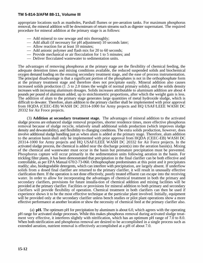
(1) Aluminum requirements. The theoretical requirement for aluminum (Al) in the precipitation pro-cess is a mole ratio of aluminum to phosphorus of 1:1. Actual case histories have indicated considerablyhigher (2:1) than stoichiometeric quantities of aluminum are needed to meet phosphorus removal objectives.Alum, Al (SO ) .18H O, is the aluminum additive most frequently used, with sodium aluminate being2 4 3 2substituted when alum addition would force the pH too low for other treatment processes. The theoreticalweight ratio of alum to aluminum is 11:1 and in practice alum weight ratios in the range of 13:1 to 22:1(depending on the degree of removal desired) have been needed. For higher removal efficiencies, the Al:Pratio must be increased. Table 15-6 lists the Al:P (and Fe:P) ratios required for 75, 85 and 95 percentphosphorus removal. Laboratory, pilot plant, or full-scale trial runs are often necessary to determine the mosteffective mineral dosages.
(2) Addition at primary treatment stage. In the primary treatment stage, the mineral is addeddirectly to the raw sewage which is then mixed, adjusted for pH (if necessary), flocculated, and clarified. Themixing and flocculation are to be carried out in specially designed units, or within existing systems at
TM 5-814-3/AFM 88-11, Volume III
15-12
appropriate locations such as manholes, Parshall flumes or pre-aeration tanks. For maximum phosphorusremoval, the mineral addition will be downstream of return streams such as digester supernatant. The requiredprocedure for mineral addition at the primary stage is as follows:
— Add mineral to raw sewage and mix thoroughly;— Add alkali (if necessary for pH adjustment) 10 seconds later;— Allow reaction for at least 10 minutes;— Add anionic polymer and flash mix for 20 to 60 seconds;— Provide mechanical or air flocculation for 1 to 5 minutes; and— Deliver flocculated wastewater to sedimentation units.
The advantages of removing phosphorus at the primary stage are the flexibility of chemical feeding, theadequate detention times and mixing conditions available, the reduced suspended solids and biochemicaloxygen demand loading on the ensuing secondary treatment stage, and the ease of process instrumentation.The principal disadvantage is that a significant portion of the phosphates is not in the orthophosphate format the primary treatment stage and therefore does not precipitate easily. Mineral addition also causesincreased solids production (1 .5 to 2.0 times the weight of normal primary solids), and the solids densityincreases with increasing aluminum dosages. Solids increases attributable to aluminum addition are about 4pounds per pound of aluminum added, up to stoichiometric proportions, after which the weight gain is less.The addition of alum to the primary stage generates large quantities of metal hydroxide sludge, which isdifficult to dewater. Therefore, alum addition to the primary clarifier shall be implemented with prior approvalfrom HQDA (CEEC-EB) WASH DC 20314-1000 for Army projects and HQ USAF/LEEE WASH DC20332 for Air Froce projects.
(3) Addition at secondary treatment stage. The advantages of mineral addition to the activatedsludge process are enhanced sludge removal properties, shorter residence times, more effective phosphorusremoval because of sludge recycle, relatively small additional solids production (which improves sludgedensity and dewaterability), and flexibility to changing conditions. The extra solids production, however, doesinvolve additional sludge handling just as when alum is added at the primary stage. Therefore, alum additionto the aeration basin shall only be implemented with prior approval from HQDA (CEEC-EB) WASH DC20314-1000 for Army projects and HQ USAF/LEEE WASH DC 20332 for Air Force projects. In theactivated sludge process, the chemical is added near the discharge point(s) into the aeration basin(s). Mixingof the chemical and wastewater must occur in the basin but premature precipitation must be prevented.Phosphorus capture will occur primarily in the sedimentation units following aeration in the basin. Fortrickling filter plants, it has been demonstrated that precipitation in the final clarifier can be both effective andcontrollable, as per EPA Manual 670/2-73-060. Orthophosphate predominates at this point and it precipitatesreadily; also, biodegradable detergents, which can interfere with precipitation, are largely absent. If underfiowsolids from a dosed final clarifier are returned to the primary clarifier, it will result in unusually effectiveclarification there. If the operation is not done effectively, poorly treated effluent can escape into the receivingwater. In order to allow for incorporating the advantages of chemical treatment in both the primary andsecondary clarifiers, provisions for future installa-tion of chemical addition and mixing facilities will beprovided at the primary clarifier. Facilities or provisions for mineral addition to both primary and secondaryclarifiers will provide flexibility of operation. Chemical treatment in both clarifiers can then be used ifexperience shows it to be the most effective technique at the particular plant involved. Initially, equipmentwill be provided only at the secondary clarifier unless bench studies or pilot plant operations show a moreeffective performance at another location or show the necessity of chemical feed at the primary clarifier also.
(a) pH. The optimum pH for precipitation by aluminum is about 6.0, which agrees with the operatingpH range for activated sludge processes. While this makes phosphorus removal during activated sludge treat-ment very effective, it interferes slightly with nitrification, which has an optimum pH range of 7.0 to 8.0.When both nitrification and phosphorus removal are desired to be accomplished in a single process such asextended aeration, nutrient removal is effectively accomplished at a pH of about 7.0.
TM 5-814-3/AFM 88-11, Volume III
15-13
(b) Velocity gradients. The velocity gradient will be determined using equation 15-1.
G values greater than 75 sec- will cause some floc disintegration and this is usually exceeded in typical1
aeration basins. To achieve better settling and therefore more effective phosphorus removal, gentle mixingwill be provided toward the end of the aeration basin or in a flocculation chamber.
(c) Weight ratio. For a combined chemical-biological phosphorus removal system, the weight ratioof the net volatile solids in the aeration basin to the aluminum added to it must exceed the Al:P weight ratio(i.e., not less than 3) to prevent the occurance of non-settleable suspended solids in the effluent from theaeration basin. The more biological solids produced from the system, the greater the aluminum dosage thatcan be used without effluent suspended solids problems.
(d) Mineral precipitates. In general, sludges containing mineral precipitates of phosphorus are stablein sludge digestion and heat treatment. The phosphates, as well as the insoluble hydroxides of excessminerals, do not resolubilize and they have no detrimental effects on the digestion process.
(4) Addition at final settling basin. At the final settling basin, phosphorus removal is very effectivebecause most of the soluble phosphates are in the orthophosphate form, which is the easiest to precipitate.The general procedure for mineral addition is essentially the same as in the primary stage. A surface overflowrate of 500 gallons per day per square foot should be used to size the final settling basin.
c. Mineral addition using iron.
(1) Iron requirements. The theoretical requirement for iron in phosphorus precipitation in terms ofmole ratio of iron to phosphorus (Fe:P) is 1:1 for the ferric ion and 3:2 for the ferrous ion. Actual plantresults indicate that the mole ratio for the ferrous ion is closer to 1:1. With the same mole ratio for ferrousand ferric ions, the weight ratio (Fe:P) is 1.8:1. As with aluminum, however, experience has indicated thatthe weight ratios are higher. The optimum pH range for ferric iron precipitation of phosphorus is 4.5 to 5.0,and for ferrous iron about 8.0. Ferrous salts cause a lowering of pH and may necessitate addition of alkali;however, alkali addition is not necessary when there is a subsequent aeration step.
(2) Effectiveness. Addition of ferric forms of iron tends to yield a fine, light floc which does not settlewell, but subsequent addition of lime and/or a polymer aids flocculation and settling. Ferrous iron additionmay present residual problems in that excess ferrous ions may not hydrolyze and settle out at a pH lower than8.0; lime addition will raise the pH and alleviate this problem. Ferrous salts yield good results when oxygenis available, such as in the activated sludge process. Ferric and ferrous iron addition, together with lime orpolymer flocculation aids, is particularly applicable to primary treatment without a subsequent activatedsludge step because there is little effluent floc carryover. However; for military installations, it is preferredthat chemical addition follow the biological reactor.
d. Mineral addition treatment schemes. Pilot plant study and full-scale plant operation will determinethe most effective and practical treatment scheme for a particular situation. This most often involves multiple-point chemical addition with recycle of mineral sludges. In the case of trickling filter plants, mineral addition,with a split of about 20 percent at the primary stage and 80 percent at final clarification with sludge recyclefrom the final settler to the primary settler; provides very effective phosphorus removal and good clarification.When removal requirements permit 5 milligrams per liter or more of phosphorus in the effluent stream,required treatment will follow the trickling filter. For very high phosphorus removal efficiencies, multi-mediafiltration is added after secondary settling (see a. above).
TM 5-814-3/AFM 88-11, Volume III
15-14
e. Mineral selection and dosages.
(1) Cost and availability. The choice of minerals should be based on cost of materials, availability ofmaterials, and process performance. Costs and availability will be determined for each particular situation.Aluminum and iron salts are in the same cost range, with aluminum salts somewhat more expensive.
(2) Side effects of various minerals. Both aluminum and iron additives will produce soluble sideproducts in the form of chlorides, sulfates, and sodium compounds, as well as some free acids and alkalis dueto hydrolysis. These side products are seldom a serious problem, however, and can be controlled by addingonly the proper amount of chemical and through the use of the automatic monitoring instrumentation. Alumand FeCl are the most commonly used mineral salts, and both cause an alkalinity drop which can lower pH3if the buffering capacity is not adequate. Iron tends to yield higher effluent residuals (around 6 milligrams perliter as Fe) than aluminum (less than 0.5 milligrams per liter as Al). Aluminum addition produces 30 to 50percent less additional solids than iron additives, and the sludge has greater dewaterability and sludge density.Aluminate and alum produce about the same amount of sludge but the aluminate sludge is considerably lessdense. Alum addition tends to produce better effluent clarity than does aluminate.
(3) Determination of dosage. Mineral dosages will be determined by the weight ratios and, whenapplicable, by pilot plant and laboratory studies and full-scale plant test runs. Alum dosages are usually in therange of 150 to 250 milligrams per liter as Al (SO ) .18H O for an average influent phosphorus concentration2 4 3 2of about 10 milligrams per liter. Typical iron dosages range from 10 to 25 milligrams per liter as Fe. Thesetypical dosages will accomplish 80 to 90 percent phosphorus removal. Greater phosphorus removal (downto residuals less than 0.5 mg/L as P) can be obtained by using multi-media filtration techniques. Refer to theEPA Process Design Manual for Phosphorous Removal.
f. Lime treatment.
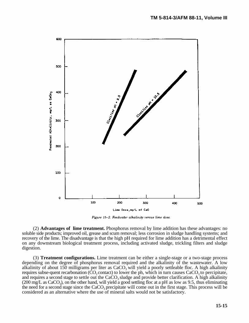
(1) Process description and conditions. Lime addition accomplishes phosphorus removal through thechemical precipitation of hydroxyapatite (Ca OH(PO ) ). Although the solubility product theoretically5 4 3determines the amount left in solution, the actual determining factor in removal efficiency is the efficiencyof the clarifiers. The precipitation of phosphorus by lime requires a high alkalinity, with a pH of 11 beingoptimum. Therefore, the lime dosage is not a function of phosphate concentration, but rather it depends onthe amount of lime necessary to attain the proper pH. This in turn is largely dependent on influent wastewateralkalinity, which is illustrated in figure 15-2. Typically, a lime dosage of as much as 400 milligrams per literas CaO will be necessary to attain a pH of 11.
TM 5-814-3/AFM 88-11, Volume III
15-15
(2) Advantages of lime treatment. Phosphorus removal by lime addition has these advantages: nosoluble side products; improved oil, grease and scum removal; less corrosion in sludge handling systems; andrecovery of the lime. The disadvantage is that the high pH required for lime addition has a detrimental effecton any downstream biological treatment process, including activated sludge, trickling filters and sludgedigestion.
(3) Treatment configurations. Lime treatment can be either a single-stage or a two-stage processdepending on the degree of phosphorus removal required and the alkalinity of the wastewater. A lowalkalinity of about 150 milligrams per liter as CaCO will yield a poorly settleable floc. A high alkalinity3 requires subse-quent recarbonation (CO contact) to lower the ph, which in turn causes CaCO to percipitate,2 3 and requires a second stage to settle out the CaCO sludge and provide better clarification. A high alkalinity3 (200 mg/L as CaCO ), on the other hand, will yield a good settling floc at a pH as low as 9.5, thus eliminating3the need for a second stage since the CaCO precipitate will come out in the first stage. This process will be3 considered as an alternative where the use of mineral salts would not be satisfactory.
TM 5-814-3/AFM 88-11, Volume III
15-16
(4) Single-stage lime treatment. The general procedure for single stage treatment is as follows:
(a) Add lime slurry to wastewater as needed to obtain a pH of 9.5 to 10.5 and provide rapid mixingfor about 30 seconds.
(b) Provide flocculation and sedimentation.
(c) If recalcination is used, thicken the sludge to 8-20 percent solids, centrifuge to 30-40 percentsolids, and then recalcine to CaO and Ca(OH) . This is usually not economical for the typical military-size2installation.
(d) After sedimentation, recarbonate for about 15 minutes to obtain the pH necessary for subsequenttreatment or discharge.
(5) Two-stage lime treatment. For two-stage treatment, the procedure is as follows:
(a) Add lime to wastewater as needed to obtain pH equal to 11-11.5 and provide mixing for about30 seconds.
(b) Provide flocculation and settling (sludge can be recalcined as in single-stage).
(c) Provide recarbonation for 5 to 15 minutes to obtain a pH of 9.5 to 10.0.
(d) Provide second stage settling (sludge recalcined as required).
(e) Again recarbonate for about 15 minutes to obtain the pH required for following treatment ordischarge.
(6) Effectiveness. Lime addition at the primary treatment stage is effective in removing from 80 to 90percent of phosphorus. It also reduces biochemical oxygen demand by 50 to 70 percent, suspended solidsby 85 percent, nitrogen by about 25 percent, and coliforms by as much as 99.9 percent. However, the igh pHnecessary for this type of treatment causes difficulties in downstream biological treatment processes.Neutralization (recarbonation) may be required before biological treatment. Primary lime treatment willreduce the organic load on the secondary treatment stage and will reduce secondary sludge by almost half;the primary sludge, however, will increase about threefold. With lime treatment in the primary treatmentstage, recalcination is often impractical because CaCo may not precipitate in sufficient quantities. A more3 effective and flexible technique is lime addition as a separate stage after secondary treatment. The advantagesof this are the flexibility of operation and the backup function of the secondary system. Either single-stageor two-stage lime treatment can be used; however, two-stage treatment is preferred becaue it produces abetter clarified effluent, has more lime recovery potential, and provides higher phosphorus removalefficiencies. The mixing, flocculation and settling units can be separate or integrated units. The integrated-type unit (upflow clarifier) works well but sludge blanket problems are encountered. Integrated units thatwork without sludge blankets and separate units are recommended.
(7) Lime addition treatment schemes. Lime addition in the primary treatment can make use ofexisting process units, or separate units can be used. Modifications such as sludge recycle to the flocculationchamber and polymer addition improve settleability of the sludge and thereby improve phosphorus removalefficiency. Mineral addition can also be used (after primary treatment with lime) to improve overallphosphorus removal efficiency. For additional information refer to the EPA Process Design Manual forPhosphorous Remova.
(8) Performance and dosage criteria. The lime requirement can vary over a wide range, dependingon operating pH and water composition. Alkalinity affects the lime dose, as can calcium hardness. One partby weight of CaO can react with from 0.89 to 1.79 parts of bicarbonate alkalinity (expressed as CaCo ); the3lower value applying to very soft waters and the higher value to very hard waters. In addition to the reactionof lime with hardness, other competing reactions occur in lime treatment of wastewater. Also, there may beincomplete reaction of the lime. These complications make calculation of lime dose difficult; consequently,determination of lime dose is largely empirical. Some approximate values are given in the U.S. EPA ProcessDesign Manual for Phosphorous Removal. The lime dose will usually be in the range of 300 to 400milligrams per liter as CaO for two-stage treatment, and from 150 to 200 milligrams per liter where single-stage treat-ment is satisfactory.
TM 5-814-3/AFM 88-11, Volume III
15-17
(9) Recarbonation. This subject is discussed in detail in the EPA Process Design Manual forPhosphorous Removal.
15-8. Land application Systems.a. Background. The use of land and biomass growth upon and within the soil has a long and interesting
history. This history, as well as a much more detailed treatment of land application of wastewaters is coveredin EPA 625/1-81-013. It should be noted that this manual is intended to be supplemented by the U.S. EPAmanual for detailed design criteria. This has been done because of the broad site-specific design conditionsthat exist for land application systems.
b. Health hazards and regulatory limitations. Because land treatment of wastewater entails a higherrisk than other treatment processes of introducing pathogenic micro-organisms and toxic chemicals intogroundwater and surface water, land treatment system design must carefully consider all possible means toprevent water supply contamination. Additionally, state and local health regulations often dictate landtreatment process design criteria. Therefore, these regulations must be consulted early in the design phaseand frequently throughout construction and operation to ensure consistent compliance.
c. Treatment capabilities and objectives. Land treatment of domestic wastewater which has undergonesecondary treatment and sludges from wastewater treatment plants may involve one of the following modes(Land treatment of wastewater after primary treatment is acceptable for isolated locations with restrictedaccess when limited to crops which are not for direct human consumption.):
— Slow rate filtration;— Rapid infiltration;— Overland flow;— Use of wetlands; and— Subsurface incorporation.
Two methods of land treatment apply to sludges:— Composting and land spreading; and— Subsurface incorporation.
d. Slow rate processes. Slow rate processes essentially mean irrigation of crops, grassland or forest landbased upon the demand of the vegetation. Typical application methods involve pipeline to row crops, surfacedistribution along furrows and ridges on the contour, sprinkler irrigation, or drip irrigation. Sprinklers anddrip irrigation require that wastewater is quite free of solid suspended matter In arid to semi-arid areas,utilization of such wastewaters-even if only to recreational areas on a military compound-should be seriouslyconsidered both for conservation and to improve local aesthetics.
e. Rapid infiltration. Rapid infiltration, often called "infiltration percolation,” involves almost completesaturation of the soil column and potentially also the rock beneath. A thick, sandy regolith with low watertable is required. Fresh water wells, well points and springs must be sufficiently far away as to not receivecontamination. Often the object is to renovate water and to recapture the effluent again with special wellsor underdrains for re-use in cooling or irrigation. Rapid infiltration may often be used to prevent the intrusionof saline water on an atoll or sandy coastal plain site. Although vegetation utilization is not planned for rapidinfiltration systems, studies have shown that use of deep rooted plants, an active root and humus mat, andtolerant vegetation will much improve the quality of the recovered water. Vegetation must be carefullyselected and, of course, some water will be lost to evapotranspiration and to production of biomass but the"living filter" will produce excellent quality water beneath the surface. (See D’Itri et al., 1982.)
f. Overland flow. This process involves a surface phenomena and depends strongly on vegetation andthe myriad organisms in the humus layer of a sloped field. Wastewater is applied over the upper reaches ofsloped terraces carefully constructed to match the contour of the land. Runoff after surface flow is collectedin ditches. Application may be from linear pipeline sprayers, plastic trickle irrigators, or using rotatingsprinklers. Overland flow could be used in forested land or to produce forage. Like the bio-filter concept,such systems not only remove suspended solids, kill pathogens and lower biochemical oxygen demand, butdramatically lower levels of nitrogen and phosphorus. (See D'Itri et al., 1984.)
TM 5-814-3/AFM 88-11, Volume III
15-18
g. Natural wetlands. Although true wetlands occupy only 3 percent of U.S. land surface, these areas offergreat potential for recharging water tables and refurbishing wastewaters. Purposeful utilization of theecologically complex habitats is new to modern man, who began to recognize around 1970 that fresh and saltwater marshes, swamps, peat bogs, cypress domes, and strands could provide excellent, very inexpensivetreatment. With proper system management and design, wetlands can treat wastewater without damagingthe existing ecology; in fact, nutrient addition can enhance productivity and increase wildlife and overallaesthetic value. During cold periods, wetlands cannot handle discharges; therefore, storage in lagoons innecessary. Loading capacity has been estimated at about 40 persons per acre. Artifical wetlands have beenconstructed on sandy soil, using impervious plastic liner. Others have been made of less pervious silt and linedwith clay. Peat bogs have been very successfully used in Minnesota and in Europe. In deep swamps-naturalor artificial-water hyacinth, duckweed, wolffia and other aquatic plants have been used to remove nutrientsfrom wastewater. Limitations of such vegetational techniques have been placed at 35 N latitude. (See Sankso
and Asano, 1976.)
h. Subsurface application. Basically, the subsurface systems involve either soil mounds or subsurfacefilters (chap 6). Such systems ae used wehre adverse soil conditions exist, such as high water table, relativelyimpermeable clay-rich soils, or shallow bedrock.
i. Composting of sludge. Where sufficient, inexpensive biomass is available (such as bark, wood chips,sawdust or other agricultural wastes), sewage may be directly mixed with organic matter and composted inopen windrows or in a ventilated building. Such processes require a great deal of biomass, but the biomassmay be dried in the sun with mechanical turning and then re-used to soak up more sewage. This systems maybe used only if flows are small. Composting has most successfully been used on sludges from any of the unitoperations discussed in this manual. Composting techniques were developed in China and India in ancienttimes, rediscovered in Europe in the 1800s, and recently have been utilized in the U.S. (Singley et al, 1982;Borchardt et al., 1981; Parr et al., 1982.)
(1) Moisture control. Sludges may be composted without addition of organic matter but are generallytoo moist. Some bulky organic matter such as the organic portion of solid waste should be used to blend withthe sludge and chipped media to entrain air and soak up moisture. Moisture content should be kept at around65-72 percent.
(2) Techniques. The easiest and least expensive composting technique involves using partially dried,recycled compost, some new "bulking agent,” and sludge mixed with a front-end loader or with mechanicalmixers to the correct moisture content. The compost is then windrowed and turned "inside-out, outside-in”several times at about one month intervals. An even simpler technique involves collecting leaves or otherbiomass during the year, piling the bulking agent in windrows, and pouring sludge into a depression shoveledalong the length of the windrow. Such simple techniques and a six-month curing period will assure sufficientpathogen kill to allow use of the compost on military base shrubs, lawns or parks. A more elaborate schemehas been developed at Beltsville by USDA. In this system, blowers, aeration pipes and, usually, a roofedbuilding allow mroe rapid "curing;; and a more continuous sludge processing. By this system, about 2.5 drytons of sludge may be composted per acre, including space for the building, office, runoff control andadequate landscaping. Before any composting technique is used, a belt of trees should be establishedsurrounding the work area for odor control (which in proper composting is minimal), dust dampening andseclusion. Partially finished compost combined with fresh sludge has been treated with earthworms, whichstabilize compost even more rapidly. Earthworms may be removed from the compost by drum screening; buton military posts, their main function would be to speed up sludge stabilization and produce an easily handled,granular soil amendment from what had previously been a noxious slurry.
TM 5-814-3/AFM 88-11, Volume III
15-19
j. Land spreading of sludges. Soil biota are capable of stabilizing most organic wastes, including oilysludges. Today, only about 25 percent of sludges are spread on land; even less are composted. However, theorganic materials in sludges are beneficial in restoring fertility to soils disturbed by mining, gravel operationsor poor agricultural practices. There are, however, some major limitations. Concentrated sludges (if notcomposted or otherwise stabilized) placed on land should be immediately covered to prevent odor productionand insect breeding.. Sludges can be sliced or injected into soil or into stubble, using special equipment. Deepsnow and deep frost will stop land spreading operations. Although heavy metals concentrations in some cityor industrial sludges hae prevented their agricultural use, this limitation should not apply to waste sludgeson military posts. Particularly useful for design of sludge land disposal is EPA Report 625/1-77-008. (Seealso Seabloom et al., 1978.)
15-9. Nitrification.
a. Process description. Nitrification occurs in two steps: first NH is converted to NO G by4 2+
Nitrosomonas bacteria; then the NO G is converted to NO G by Nitrobacter bacteria. This process is limited2 3by the relatively slow growth rate of Nitrosomonas. The following discussion is mainly applicable to activatedsludge processes and nitrification. Additional information may be found in EPA Process Design Manual forNitrogen Control.
b. Single-stage nitrification. When nitrification utilizing the activated sludge process is designed as asingle stage, a longer detention time (12 to 24 hours as compared with the usual 2 to 8 hours) is necessaryin the aeration basin in order to provide an effective microbial population. This is interpreted in terms of"mean solids residence time” (SRT), which is defined as the amount of mixed-liquor, volatile suspended solidsunder aeration (in pounds) divided by the sum of suspended solids wasted and suspended solids lost in theeffluent (in pounds per day). The mean solids residence time will be maintained at 10 to 20 days or longer,depending on the temperature; in terms of hydraulic detention time, 12 to 24 hours is typical. Temperaturehas a significant effect on the nitrification reaction rate, which approximately doubles for every 10 C rise ino
temperature between 6 C and 25 C. A minimum dissolved oxygen level of 1.0 milligrams per liter is sufficiento o
for nitrification. However, since dissolved oxygen concentration is a critical parameter, the aeration systemwill be designed to provide a residual dissolved oxygen of 2.0 milligrams per liter and pH 8.5, using limeaddition if necessary. The optimum pH has been reported to be 8.4. Lime requirements will vary with thetemperature and must be determined for each case. Nitrification consumes approximately 7.5 milligrams perliter of alkalinity per milligram per liter ammonia nitrogen oxidized.
(1) Effect of toxic substances. Nitrification can be inhibited by certain toxic substances, such ashalogen-substituted phenolic compounds, thiourea and its derivatives, halogenated solvents, heavy metals,cyanides, phenol, and cresol. These, however, are usually associated with industrial wastes. (Table 10-4 givesinformation on materials that inhibit nitrification.)
(2) Design criteria for single-stage nitrification in activated sludge, extended aeration processes.The design of single-stage nitrification systems will provide for:
(a) Increased aeration tank capacity and additional aeration to maintain dissolved oxygen level at 2.0milligrams per liter;
(b) A hydraulic detention time of 12 to 24 hours;
(c) Sludge handling equipment suited to light, poorly compacted sludge, with recycle capacity of 150percent of average flow;
(d) Food-to-micro-organism ratio of less than 0.25 pounds biochemical oxygen demand per poundmixed liquor, volatile suspended solids;
(e) Sludge retention time during winter conditions in excess of 20 days; and
(f) Lime feeding equipment to provide alkalinity at a rate of 7.5 milligrams per liter per milligram perliter of ammonia oxidized, and a pH between 8.0 and 8.5.

TM 5-814-3/AFM 88-11, Volume III
15-20
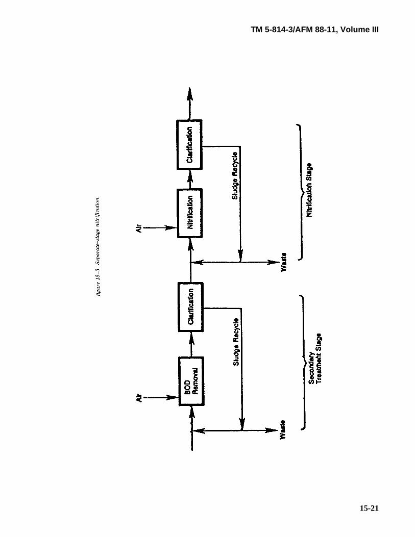
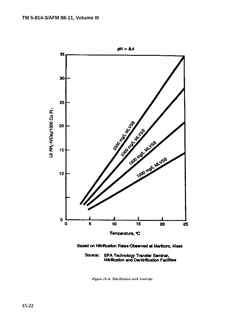
c. Separate-stage nitrification. Separate-stage nitrification simply separates the nitrification process fromthe activated sludge process. A typical system is illustrated in figure 15-3. The main advantage to this systemis that it allows individual optimization of the activated sludge and nitrification processes in terms of hydraulicand organic loadings. The relationship between ammonia removal rate and mixed liquor, volatile suspendedsolids concentration is shown in figure 15-4. There is little sludge waste in the separate nitrification systemand total sludge recycle is to be used. Detention time will be from 3 to 5 hours, based on influent flow withclarifier overflow rates between 500 and 800 gallons per day per square foot. Diffused air will be suppliedat approximately 1 standard cubic foot per minute per gallon of wastewater treated.
TM 5-814-3/AFM 88-11, Volume III
15-21
TM 5-814-3/AFM 88-11, Volume III
15-22
TM 5-814-3/AFM 88-11, Volume III
15-23
d. Nitrification in trickling filter plants. Low biochemical oxygen demand loadings (less than 5 poundsper day per 1,000 cubic feet) and high wastewater temperature (20 C or higher) are necessary for good o
nitrification (80-90 percent) in trickling filters although they are often run at 12 degrees Centigrade with someloss of overall efficiency. A trickling filter filled with plastic packing can obtain 90 percent nitrification ofsecondary effluent at a loading rate of 0.05 gallons per minute per cubic foot. Year-round nitrificationfacilities must be designed for the lowest wastewater temperatures experienced in the winter months. In thisinstance, the required filter volume will be much greater than that required for seasonal nitrification and willrequire at least two-stage treatment.
e. Rotating biological contactors as nitrification units. Ninety percent nitrification can be accomplishedusing rotating biological contactors if the influent biochemical oxygen demand is less than 150 milligrams perliter and the hydraulic application rate is 2 gallons per day per square foot or less. For further information,consult the EPA Process Design Manual for Nitrogen Control.
f. Air stripping. Ammonia, in the molecular form, is a gas which dissolves in water to an extentcontrolled by the partial pressure of the ammonia in the air adjacent tot he water. Therefore, ammoniaremoval from wastewater can be accomplished by contacting water droplets with large amounts of ammonia-free air. This process is desorption, but is commonly referred to as ammonia stripping. For additionalinformation, refer to the EPA Process Design Manual for Nitrogen Control.
15-10. Denitrification.a. Suspended growth denitrification. Denitrification is performed by heterotrophic anaerobic organisms
and, therefore, requires an organic carbon source and anaerobic conditions. Suspended growth denitrificationwill provide gentle mixing (no aeration) with the mixed liquor being clarified. The effluent is aerated toprovide dissolved oxygen and to drive off entrained nitrogen, and the sludge is recycled to the contact tank.Methanol is the most common organic carbon source used and is usually applied at a dosage of 2 to 4 poundsmethanol per pound of nitrate nitrogen removed. This dosage will be carefully adjusted according to nitrateconcentra tion and temperature in order to avoid the effects of under-dosage and over-dosage. Raw orpartially treated sewage and sludge can be used as a carbon source but yield lower denitrification efficiencies.Typical design factors for this system include:
(1) Mixed liquor volatile suspended solids concentrations of 1,500 to 2,500 milligrams per liter;
(2) Detention time of 4 hours;
(3) Clarifier overflow rates not more than 600 gallons per square foot;
(4) Dissolved oxygen levels of up to 0.5 milligrams per liter (pH 7.0);
(5) Optimum pH from 6.5 to 7.5;
(6) 5 minutes of effluent aeration; and
(7) Sludge recycle from 50 to 100 percent of average flow.
Temperature effects are very significant and should be kept in mind when designing contact tanks since a 10degress Centigrade decrease would require twice the tank capacity.
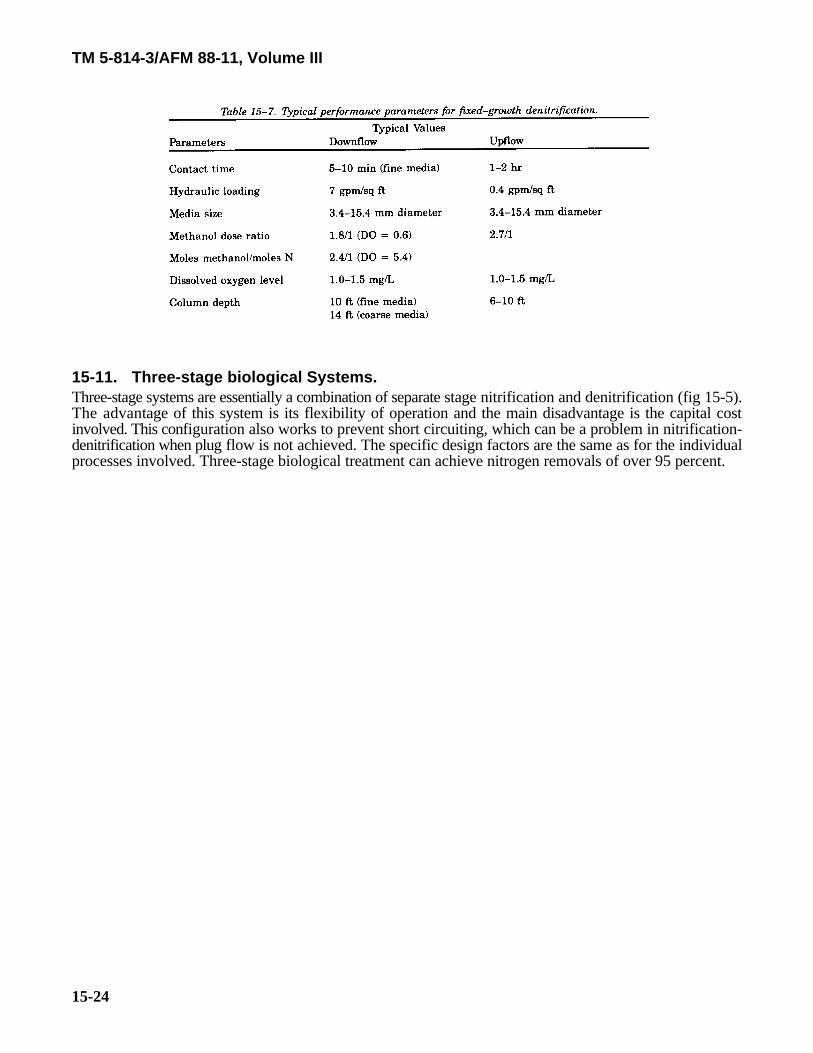
b. Fixed denitrification. Fixed denitrification utilizes a flooded packed column, with denitrifyingmicrobial populations attached on the media surface. Sand, activated carbon, gravel, coal, and plastic packingcan be used; with the finer media having shorter contact times. Columns can be either downflow or upflowconfiguration. Upflow columns have much longer contact times and operate at lower hydraulic loadings, butthey are more efficient at lower temperatures than downflow columns. Temperature again is a very significantfactor affecting denitrification efficiency. Typical design factors for both downflow and upflow denitrificationare given in table 15-7. Fixed denitrification is capable of nitrate removal efficiencies of over 90 percent;however, the efficiency of the overall nitrification-denitrification process is limited by the performance of thenitrification system (i.e., around 90 percent nitrogen removal).
TM 5-814-3/AFM 88-11, Volume III
15-24
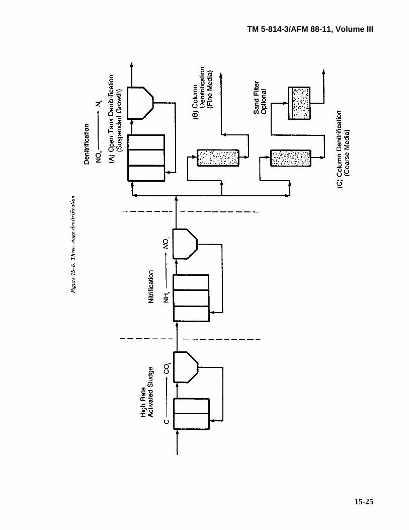
15-11. Three-stage biological Systems.Three-stage systems are essentially a combination of separate stage nitrification and denitrification (fig 15-5).The advantage of this system is its flexibility of operation and the main disadvantage is the capital costinvolved. This configuration also works to prevent short circuiting, which can be a problem in nitrification-denitrification when plug flow is not achieved. The specific design factors are the same as for the individualprocesses involved. Three-stage biological treatment can achieve nitrogen removals of over 95 percent.
TM 5-814-3/AFM 88-11, Volume III
15-25

TM 5-814-3/AFM 88-11, Volume III
15-26
15-12. Anaerobic contact process.A further development of the high-rate digestion process allows separation and recycling of digested sludgesolids. Like the activated sludge process, detention and mean cell residence times are controlled. Denitrifica-tion within these contact vessels approached 95 percent.