Embed Size (px)
Citation preview
CHAPTER 17
STATE OF THE ART
17.1 INTRODUCTION
Dense wavelength division multiplexing (DWDM) is a technology that dependsheavily on optical components, many of which are state of the art, produced in lowvolumes, and thus costly. Consequently, research continues to develop new and bet-ter performing optical components as well as integrated optical compact componentsat low cost. Amplifiers, multiplexers, filters, signal conditioners, transmitter arrays,and receiver arrays are among the items in development. These components shouldperform such that center frequencies and power level are compatible, conforming tostandard physical interfaces. In addition, standard transport protocols and networkmanagement standards are necessary for interoperability and uniform quality of ser-vice. This chapter addresses some areas in which intense research is being conducted.Areas not included are not less important; we simply cannot mention them all.
17.2 CURRENT ISSUES
17.2.1 Optical Materials
Artificial new solid-state optical materials with unusual characteristics are in the ex-perimental stage. Such characteristics are based on extremely high values of indexof refraction, polarization, and switching properties when a varying field is applied.Other properties are based on optical energy absorption and coherent photolumines-ence in a wide spectrum range that covers the C- and L-bands, or beyond.
Experimental materials in addition to solid-state materials include organic com-pounds that can absorb one wavelength and emit another (wavelength conversion,memory) or can absorb a wavelength and emit it when stimulated (memory).
211
212 Part V DWDM Current Issues and Research
17.2.2 Integration
Optical integration will also be the "next step" in the evolution of optical devices.Integration, combined with sophisticated packaging, will yield devices with complexfunctionality that could perform optical signal processing with no need to convert theoptical signal to electrical. Soon optical devices will follow an evolutionary pathsimilar to those of the transistor and the intergrated devices. A few years ago it wasa dream to approach a million transistors in a chip. Today, this dream is past tenseand unimpressive.
17.2.3 Lasers and Receivers
Low-cost lasers are important in many applications. Some researchers are even ex-perimenting with organic compounds to create inexpensive high-density plasticlasers and other components. Development of high-power tunable lasers that are in-expensive and laser arrays with narrow line width and sufficient optical power forDWDM applications is another activity. Tunable receivers and receiver arrays at lowcost are in development. In the same venue, some techniques generate hundreds ofwavelength channels with a single laser.
A similar activity is to produce tunable receivers and receiver arrays at low cost.In this venue, some have succeeded to generate hundreds of wavelength channelswith a single laser.
17.2.4 Line Coding Techniques
As the number of wavelengths per fiber increases (approaching 1000), and as thenumber of bits per second increase (currently 40 Gb/s), the optical signal becomesmore vulnurable to errors due to dispersion and other linear and nonlinear phenom-ena. This vulnurability increase, however, should not compromise in any way thequalityof the signal; the signal must be maintained at acceptable and expected levelsdespite the aggregate bandwidth benefit. This means that signal error countermea-sures must be developed to compensate for and correct induced errors on the signal.
Such countermeasures may be based on the new intersymbol interference (lSI)resistant coding techniques, or they may be based on error detection/correctionmechanisms that are able to locate and correct errors, or a combination of both linecoding and error correction. A metric of good line coders (for 10 Gb/s) is to producean acceptable eye diagram at the receiver such that the uncertainty of the state (lor0) of the received bits is less than 1 bit per second per hertz « 1 b/slHz). Error rates(as specified in ITU-T standards) may be les than 10- 12 BER.
17.2.5 Optical Cross-Connect
As the number of wavelengths increases beyond 200 and approaching 1000, 1000 X
1000 low-loss, nonblocking, and fast-switching optical cross-connect devices are achallenge. Although there have been interesting proposals to produce such devices,it remains to be seen which become commercial products.
In addition, there is research under way to develop ultrafast switching devices
Chapter 17 State of the Art 213
based on glasses that contain chalcogenides. Chalcogenide glasses (Ge-Se-Te) havean index of refraction 1000 times higher than Si02 glass, an ultrafast response time(they can switch from high nonlinear absorption to low) in less than 1 ps, a low lin-ear loss a low nonlinear loss and a high figure of merit (FOM), in the order of 20.
17.2.6 Optical Add-Drop Multiplexers
Low-cost optical add-drop multiplexers (OADMs) are key components in opticalnetworks. OADM devices allow the dropping off and addition of wavelengths selec-tively, and their passage through all other wavelengths. Low-loss and low-costOADM devices that add or drop groups of wavelengths on a selective basis are an-other challenge.
Fibers will soon be connected to the desktop computer and multimedia devices.The 1960s bit rate to the home of 64 Kb/s will be higher than 1.5 to 2 Mb/s in the2000s (in some cases it may be up to 50 Mb/s). These applications will demand ex-tremely low-cost and reliable optical devices (transmitters, receivers, and filters).
17.2.7 Optical Memories and Variable Delay Lines
Optical delay lines consist of fiber cut at lengths that, based on travel time of lightin the fiber medium, can delay light by a fixed amount of time. This principle is al-ready used in monolithic interferometers. However, compact optical devices that canstore a light pulse of the necessary length would allow construction of a true opticalmemory and a variable delay. Such devices could be used to treat light pulses likeelectronic pulses and to construct optical integrated subsystems with time divisionconcepts as well as computational properties.
17.2.8 Nonintrusive Optical Monitoring
Nonintrusive optical signal monitoring is difficult to perform but important. The op-tical signal needs to be monitored for power, noise, "eye" closure (enough power tobe detected by the receiver), wavelength accuracy, and line width. In addition, if awavelength channel carries supervisory information, including telemetry, some in-formation needs to be terminated, whereas some other needs to be passed transpar-ently. In general, nonintrusive optical monitoring reduces the amount of opto-electronics, reduces latency, and increases reliability.
17.2.9 DWDM System Dynamic Reconfigurability
System dynamic reconfigurability implies dynamic wavelength and bandwidth man-agement and thus, fast tunable optical devices (lasers, receivers, and filters), as wellas fast and intelligent protocols.
17.2.10 Optical Backplanes
The incoming optical signal at a port will be monitored and the optical signal willbe directly coupled to an optical backplane that routes the signals to another unit
214 Part V DWDM Current Issues and Research
of the system (e.g., an optical cross-connect fabric). Optical backplanes providea cost-effective and compact solution to an all-optical system.
17.2.11 Standards
Currently, standards have been issued (see end-of-chapter listing), others are beingdrafted, and others are in the proposal phase. As DWDM evolves, more proposalsare expected to be submitted to address emerging issues on all aspects of DWDMsystems and networking. The standards bodies are evaluating the proposed stan-dards.
17.2.12 Network Issues
DWDM in optical networks is new territory and thus many new issues emerge.These issues boil down to performance, efficiency, flexibility, reliability, scalability,and cost. Since a vast amount of work is in progress to resolve these issues, weshould identify some of them.
• Are all nodes in the DWDM network optically transparent, or are theyopaque?
• If they are transparent, how do we establish end-to-end (from optical sourceto destination) wavelength connectivity?
• How do we determine the optimum number of optical components on the end-to-end optical connection (the number of optical components may not be thesame from one end to the other) throughout the network?
• How do we execute performance monitoring in the optical regime?
• What are the rules and mechanisms for fault detection, fault avoidance,and faultrestoration on the optical node, optical network, level, and wavelength levels?
• What are the rules and the mechanisms for DWDM network survivability?
• How do we assure service reliability, service integrity, and quality of servicein DWDM?
• What are the mechanisms for optical network management?
• How do we transport over the same DWDM network a variety of services IP,SONET/SDH, ATM, Ethernet-type, and others)?
• How do we assign or reassign wavelengths across a DWDM optical network?
• How do we assure security of network and of data?
• As DWDM systems are further deployed and evolve, how do we cope withnew emerging issues?
17.2.13 Ultrahigh Speeds at Longer Spans
DWDM systems enable a tremendous bandwidth per fiber. However, competitionand pressures for service at lower cost fuel research and thinking. Once a speed has
Chapter 17 State of the Art 215
been achieved, a higher speed is contemplated. Once transmission over a longer fiberspan without amplification has been achieved, a longer span yet is planned for.Currently, 40 Gb/s at 8 x 80 km 2 spans (with amplification) is reality. If signal in-tegrity, device noise, and loss figures improve, then optical signal loss, signal noise,and bit error rate will be reduced, allowing longer yet fiber spans (for the same re-ceiver sensitivity as before) . In addition, improvements in forward error correctiontechniques (e.g., digital wrapper) further reduce BER and further extend the fiberspan.
17.2.14 Opaque Systems
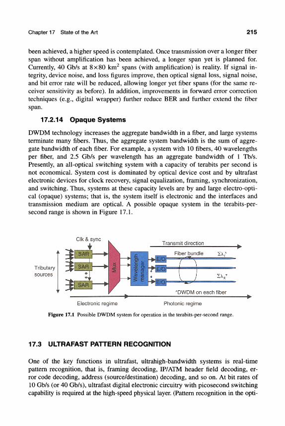
DWDM technology increases the aggregate bandwidth in a fiber, and large systemsterminate many fibers. Thus , the aggregate system bandwidth is the sum of aggre-gate bandwidth of each fiber. For example, a system with 10 fibers, 40 wavelengthsper fiber, and 2.5 Gb/s per wavelength has an aggregate bandwidth of 1 Tb/s .Presently, an all-optical switching system with a capacity of terabits per second isnot economical. System cost is dominated by optical device cost and by ultrafastelectronic devices for clock recovery, signal equalization, framing, synchronization,and switching. Thus, systems at these capacity levels are by and large electro-opti-cal (opaque) systems; that is, the system itself is electronic and the interfaces andtransmission medium are optical. A possible opaque system in the terabits-per-second range is shown in Figure 17.1.
Tributarysources
Electronic regime
Transmit direction
*DWDM on each fiber
Photonic regime
Figure 17.1 Possible DWDM system for operation in the terabits -per-second range.
17.3 ULTRAFAST PATTERN RECOGNITION
One of the key functions in ultrafast, ultrahigh-bandwidth systems is real-timepattern recognition, that is, framing decoding, IP/ATM header field decoding, er-ror code decoding , address (source/destination) decoding, and so on. At bit rates of10 Gb/s (or 40 Gb/s), ultrafast digital electronic circuitry with picosecond switchingcapability is required at the high-speed physical layer. (Pattern recognition in the opti-
216 Part V DWDM Current Issues and Research
cal regime-all photonic and without electronics-has not been cost-effectively imple-mented yet.) Thus, depending on data traffic type, millions of patterns per secondmay need to be recognized, and perhaps each one will have to be translated to anotherpattern.
This ultrafast electronic "recognizer" circuitry should not be complex; it may belimited to clock circuitry and a simple shift register to capture a byte or a word inreal time. Reading bytes or words reduces the recognition speed by 8 or 16 times thebit rate. Thus , the "recognizer" can operate a little more slowly-in the nanosecondrange, not the picosecond.
Devices that can perform fast pattern recognition and translation are known.Content-addressable memories (CAM) are one example . When a pattern is appliedat the parallel data input of the CAM, the device recognizes it and translates it to an-other pattern , if needed. The complete operation takes place in one clock cycle.However, commercially available CAMs operate in the order of 100 ns, the patternset is limited, and the power consumption is relatively high, increasing complexityand thus cost of the system.
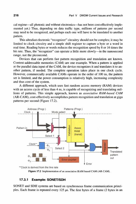
A different approach, which uses fast random access memory (RAM) deviceswith an access cycle of less than 4 ns, is capable of recognizing and translating mil-lions of patterns. This simple approach, known as associative RAM-based CAM(AR-CAM), cost-effectively accomplishes pattern recognition and translation at gigapatterns per second (Figure 17.2).
Translatedpatternout
Error counter
Clock""
Address (Progr.) Patterns (Progr.)..---C_M~~'- -~~--~--A~=------------------32 RAM~ (transl)
Error""Clock is derived from the line rate
Figure 17.2 Implementation of an associative RAM-based CAM (AR-CAM).
17.3.1 Example: SONET/SDH
SONET and SDH systems are based on synchronous frame communication princi-ples. Each frame is repeated every 125 IJs. The first bytes of a frame (2 bytes in an
Chapter 17 State of the Art 217
OC-3, 8 bytes in an OC-12) contain a fixed pattern that is used for synchronizationpurposes. Other bytes are used for error control, pointers in the payload area, pro-tection switching, and so on. See Table 14.2 for SONET and SDH rates.
A signal at -10 Gb/s that consists of 196 OC-3 multiplexed signals presents achallenge in recognizing synchronization patterns and other patterns in the overheadsection of OC-3 frames. AR-CAMs with an address bus 8 bits wide can cope com-fortably with such high pattern recognition rates.
17.3.2 Example: ATM
ATM consists of 53-byte frames that do not all arrive synchronously. However, ATMcells may have been mapped onto the STM payload. ATM cells consist of a 5-byteheader and a 48-byte payload. The 5 bytes of the ATM cell header are partitioned (inthe case of network-to-network interface or NNI) as follows:
• Virtual path identifier: 12 bits
• Virtual channel identifier: 16 bits
• Payload type identifier and cell loss priority: 4 bits
• Head error control: 8 bits
In a high cell-rate STM case, there may be 350,000 ATM cells per second. That is,pattern recognition in 1.4 flS is required. However, assuming that there are 16 in-coming sources, each with 350,000 cells/s, then recognition time is 8.5 ns. A singleAR-CAM could accomplish this task very comfortably, whereas a CAM could not.Thus, ATM cells may be quickly recognized and rerouted with the minimum amountof latency.
17.3.3 Example: Internet Protocol
IP packets based on Internet Protocol version 4 (IPv4) consist of an IP header (6 x32 bits) and a datagram (up to 65,535 octets); future IP versions such as IPv6 willbe similarly constituted. A router fragments the datagram and attaches to each onean IP packet header. Fragments may not be of equal length. Based on the networkused (SONET/ATMIother) to transport IP packets, the packet may be further seg-mented by the segmentation and reassembly (SAR) function. The receiving terminalreassembles all fragments, based on flags and offset (flags and offset are containedin the IP header). The IP header contains information such as the following:
• Version field (IP format, version of protocol): 4 bits
• Internet header length (measured in 32-bit words): 4 bits
• Type of service (QoS): 8 bits
• Total length (of datagram, up to 65,535 octets): 16 bits
218 Part V DWDM Current Issues and Research
• ID (unique for each datagram used to reassemble): 16 bits
• Flags (0, DF, DM): 3 bits
• Fragment offset (up to 8192 fragments): 12 bits
• Time to live (time to remain on Internet): 8 bits
• Protocol (upper layer protocol): 8 bits
• Header checksum: 16 bits
• Source address.: 32 bits (IPv4), 128 bits in colon hexadecimal (IPv6)
• Destination address.: 32 bits (IPv4), 128 bits in colon hexadecimal (IPv6)
• Options and padding: 32 bits
Thus, AR-CAMs may be used to recognize multiple IP packets fast (within a clockcycle), with negligible latency, thus addressing one of the optical networks issue,namely, fast routability (via fast recognition).
17.4 CURRENT RESEARCH: WAVELENGTH BUS
Current DWDM systems have a number of wavelengths (channels) in a fiber buteach wavelength is allocated for one channel. Therefore, the total bandwidth capac-ity of the DWDM fiber is the sum of bandwidth of each channel. To maximize theefficiency of the bandwidth per fiber, wavelengths may be organized in parallel buses(e.g., five buses each consisting of 8 wavelengths), or fewer buses and individualwavelengths to meet different requirements and provide compatibility with existingsystems.
Now, consider a multiplicity of data tributaries. In addition, consider thatbytes from each tributary are in parallel (not serial) and the tributaries are byte-multiplexed, forming a multiplexed 8-wavelength bus. The parallel multiplexed datais now transmitted over 8 wavelengths of an 8-wavelength bus.
All wavelengths of a bus carry modulated information at the same bit rate (e.g.,10 Gb/s). In this case, the total bandwidth of the bus is 8 x 10 = 80 Gb/s. Because trib-utaries are multiplexed, many tributaries, each at a different rate, may be multi-plexed, up to a total aggregate of 80 Gb/s. This method establishes flexibility, scala-bility, and efficient bandwidth utilization that typically cannot be readily achievedwith traditional DWDM systems where, for example, each of 8 wavelength channelswould carry data at a different rate. In addition, an 8-wavelength bus allows for morethan eight users to share the total aggregate bandwidth, as opposed to traditionalDWDM, which allows for as many users as the number of wavelengths in the fiber.
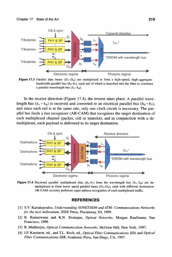
Figure 17.3 illustrates a multiplicity of tributaries that are terminated at a phys-ical interface (PRY). If serial data are converted into parallel (SP), D i , all paralleldata are multiplexed by the multiplexer unit to form a high-speed, high-aggregate-bandwidth parallel bus (bo-b7 ) , each rail of which modulates a lasertransmitter to form a parallel wavelength bus (A. I - A.s), with each rail transmitting atthe same rate.
Chapter 17 State of the Art 219
Tributaries
Tributaries
Tributaries
Transmit direction
*DWDM with wavelength bus
Electronic regime Photonic regime
Figure 17.3 Parallel data buses (DI-DN ) are multiplexed to form a high-speed, high-aggregate-bandwidth parallel bus (bo-b7 ) , each rail of which is launched into the fiber to constructa parallel wavelength bus (1"1-1..8),
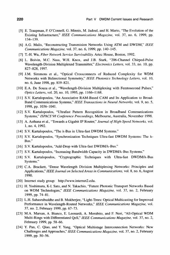
In the receive direction (Figure 17.4), the reverse takes place. A parallel wave-length bus (At-As) is received and converted to an electrical parallel bus (bo-b7 ) ,
and since each rail is at the same rate, only one clock circuit is necessary. The par-allel bus feeds a fast recognizer (AR-CAM) that recognizes the target destination ofeach multiplexed channel (packet, cell or timeslot), and in conjunction with a de-multiplexer, each payload is delivered to its target destination.
Destinations
Electronic regime
*DWDM with wavelength bus
Photonic regime
Figure 17.4 Received parallel multiplexed data (bo-b7 ) from the wavelength bus (1..1-1..8) are de-multiplexed to form lower speed parallel buses (D 1-DN ) , each with different destination .AR-CAM circuitry performs rapid address recognition of each multiplexed traffic.
REFERENCES
[1] S.V. Kartalopoulos, Understanding SONETISDH and ATM: Communications Networksfor the next millennium , IEEE Press, Piscataway, NJ, 1999.
[2] R. Ramaswami and K.N. Sivarajan, Optical Networks, Morgan Kaufmann, SanFrancisco, 1998.
[3] B. Mukherjee, Optical Communication Networks, McGraw-Hill, New York, 1997.
[4] LP. Kaminow, ed., and T.L. Koch, ed., Optical Fiber Communications IlIA and OpticalFiber Communications IIIB, Academic Press, San Diego, CA, 1997.
220 Part V DWDM Current Issues and Research
[5] E. Traupman, P. O'Connell, G. Minnis, M. Jadoul, and H. Mario, "The Evolution of theExisting Infrastracture," IEEE Communications Magazine, vol. 37, no. 6, 1999, pp.134-139.
[6] A.G. Malis, "Reconstructing Transmision Networks Using ATM and DWDM," IEEECommunications Magazine, vol. 37, no. 6, 1999, pp. 140-145.
[7] T.-H. Wu, Fiber Network Service Survivability. Artec House, Boston, 1992.
[8] L. Boivin, M.C. Nuss, W.H. Knox, and J.B. Stark, "206-Channel Chirped-PulseWavelength-Division Multiplexed Transmitter," Electronics Letters, vol. 33, no. 10, pp.827-828, 1997.
[9] J.M. Simmons et aI., "Optical Crossconnects of Reduced Complexity for WDMNetworks with Bidirectional Symmetry," IEEE Photonics Technology Letters, vol. 10,no. 6, June 1998, pp. 819-821.
[10] E.A. De Souza et aI., "Wavelength-Division Multiplexing with Femtosecond Pulses,"Optics Letters, vol. 20, no. 10, 1995, pp. 1166-1168.
[11] S.V. Kartalopoulos, "An Associative RAM-Based CAM and Its Application to Broad-Band Communications Systems," IEEE Transactions in Neural Networks, vol. 9, no. 5,1998, pp. 1036-1041.
[12] S.V. Kartalopoulos, "Ultrafast Pattern Recognition in Broadband CommunicationsSystems," ISPACS'98 Conference Proceedings, Melbourne, Australia, November 1998.
[13] A. Asthana et al., "Towards a Gigabit IP Router," Journal ofHigh-Speed Networks, vol.1, no. 4, 1992.
[14] S.V. Kartalopoulos, "The A-Bus in Ultra-fast DWDM Systems."
[15] S.V. Kartalopoulos, "Synchronization Techniques Ultra-fast DWDM Systems: The A-Bus."
[16] S.Y. Kartalopoulos, "Add-Drop with Ultra-fast DWDM/A-Bus."
[17] S.Y. Kartalopoulos, "Increasing Bandwidth Capacity in DWDM/A-Bus Systems."
[18] S.Y. Kartalopoulos, "Cryptographic Techniques with Ultra-fast DWDM/A-BusSystems."
[19] C.A. Brackett, "Dense Wavelength Division Multiplexing Networks: Principles andApplications," IEEE Journal on Selected Areas in Communications, vol. 8, no. 6, August1990.
[20] Internet study group: http://www.internet2.edu.
[21] H. Yoshimura, K-I. Sato, and N. Takachio, "Future Photonic Transport Networks Basedon WDM Technologies," IEEE Communications Magazine, vol. 37, no. 2, February1999,pp.74-81.
[22] L.H. Sahasrabuddhe and B. Mukherjee, "Light-Trees: Optical Multicasting for ImprovedPerformance in Wavelength-Routed Networks," IEEE Communications Magazine, vol.37, no. 2, February 1999, pp. 67-73.
[23] M.A. Marsan, A. Bianco, E. Leonardi, A. Morabito, and F. Neri, "All-Optical WDMMulti-Rings with Differentiated QoS," IEEE Communications Magazine, vol. 37, no. 2,February 1999, pp. 58-66.
[24] Y. Pan, C. Qiao, and Y. Yang, "Optical Multistage Interconnection Networks: NewChallenges and Approaches," IEEE Communications Magazine, vol. 37, no. 2, February1999, pp. 50-56.
Chapter 17 State of the Art 221
[25] K. Sato, Advances in Transport Network Technologies-Photonic Networks, ATM andSDH, House, Boston, 1996.
[26] N. Takachio and S. Ohteru, "Scale of WDM Transport Network Using Different Typesof Fibers," IEEE Journal on Selected Areas in Communications, vol. 16, no. 7,1998, pp.1320-1326.
[27] B. Mukhergie, Optical Communications Networks, McGraw-Hill, New York, 1997.
[28] P.E. Green Jr., Fiber Optic Networks, Prentice Hall, Englewood Cliffs, NJ, 1993.
[29] M. A. Marsan et al., "Daisy: A Scalable All-Optical Packet Network with Multi-FiberRing Topology," Computer Networks and ISDN Systems, vol. 30, 1998, pp. 1065-1082.
[30] I. Gidon and Y. Ofek, "MetaRing-A Full-Duplex Ring with Fairness and SpatialReuse," IEEE Transactions on Communications, vol. 41, no. 1, January 1993, pp.110-120.
[31] S. Ohteru and K. Inoue, "Optical Time Division Multiplexer Utilizing ModulationSignal Supplied to Optical Modulation as a Reference," IEEE Photon, vol. 8, no. 9,1996,pp.1181-1183.
[32] J.R. Freer, Computer Communications and Networks, IEEE Press, Piscataway, NJ, 1996.
[33] R. Handel and M.N. Huber, Integrated Broadband Network, Addison Wesley, Reading,MA,1991.
[34] R.D. Gitlin, J.F. Hayes, and S.B. Weinstein, Data Communications Principles, Plenum,New York, 1992.
[35] S.V. Kartalopoulos, "A Manhattan Fiber Distributed Data Interface Architecture,"Globecom'90, San Diego, CA, December 2-5,1990.
[36] S.V. Kartalopoulos, "Disaster Avoidance in the Manhattan Fiber Distributed DataInterface Network," Globecom'93, Houston, TX, December 2,1993.
[37] S.V. Kartalopoulos, "A Plateau of Performance?" IEEE Communications Magazine,September 1992, pp. 13-14.
[38] A.E. Willner, "Mining the Optical Bandwidth for a Terabit per Second," IEEE Spectrum,April 1997, pp. 32-41.
[39] S.V. Kartalopoulos, Understanding Neural Networks and Fuzzy Logic, IEEE Press,Piscataway, NJ, 1995.
[40] Members of the Technical Staff, Transmission Systems for Communications, BellTelephone Laboratories, Murray Hill, NJ, 1982.
[41] J. Nellist, Understanding Telecommunications and Lightwave Systems, IEEE Press,Piscataway, NJ, 1996.
[42] W.Y. Zhou and Y. Wu, "COFDM: An Overview," IEEE Transactions on Broadcasting,vol. 41, no. 1, March 1995, pp. 1-843.
[43] K.-I. Kitayama, "Code Division Multiplexing Lightwave Networks Based upon OpticalCode Conversion," IEEE Journal on Selected Areas in Communications, vol. 16, no. 7,September 1998, pp. 1309-1310.
[44] T. Shiragaki et aI., "Optical Cross-Connect System Incorporated with Newly Devel-oped Operation and Management System," IEEE Journal on Selected Areas inCommunications, vol. 16, no. 7, September 1998, pp. 1179-1189.
[45] S. Johansson et aI., "A Cost-Effective Approach to Introduce an Optical WDM Networkin the Metropolitan Environment," IEEE Journal on Selected Areas in Communications,vol. 16, no. 7, September 1998, pp. 1109-1122.
222 Part V DWDM Current Issues and Research
[46] Y. Miyao and H. Saito, "Optimal Design and Evaluation of Survivable WDM TransportNetworks," IEEE Journal on Selected Areas in Communications, vol. 16, no. 7,September 1998, pp. 1190-1198.
[47] B. Van Caenegern, W. Van Parys, and P.M. Demeester, "Dimensioning of SurvivableWDM Networks," IEEE Journal on Selected Areas in Communications, vol. 16, no. 7,September 1998, pp. 1146-1157.
[48] O. Crochat and J-Y. Le Boudec, "Design Protection for WDM Optical Networks," IEEEJournal on Selected Areas in Communications, vol. 16, no. 7, September 1998, pp.1158-1165.
[49] M.W. Maeda, "Management and Control of Transparent Optical Networks," IEEEJournal on Selected Areas in Communications, vol. 16, no. 7, September 1998, pp.1008-1023.
[50] E. Karasan and E. Ayanoglu, "Performance of WDM Transport Networks," IEEEJournal on Selected Areas in Communications, vol. 16, no. 7, September 1998, pp.1081-1096.
STANDARDS
[1] ANSI T1X1.5/99-002, "A Proposal for Providing Channel-Associated Optical ChannelOverhead in the OTN," George Newsome and Paul Bonenfant, Lucent, January 1999.
[2] ANSI TIX1.5/99-oo3, "A Proposed Implementation for a Digital 'Wrapper' for OChOverhead," James Ballintine, Lucent, January 1999.
[3] ANSI T1X1.5/99-004, "Optical Channel Overhead Carried on the Optical SupervisoryChannel," George Newsome and Paul Bonenfant, Lucent, January 1999.
[4] ANSI T1X1.5/99-146, "Proposed OCh-OR Assignments for the OCh Frame," JamesBallintine, Lucent, May 1999.


![[PPT]Microbiology Chapter 17 - Austin Community College … ppt/ch 17 ppt.ppt · Web viewMicrobiology Chapter 17 Chapter 17 (Cowan): Diagnosing infections This is wrap up chapter](https://img.pdfslide.net/doc/110x75/5aee76d27f8b9a572b8cc178/pptmicrobiology-chapter-17-austin-community-college-pptch-17-pptpptweb.jpg)