Embed Size (px)
Citation preview

Fundamentals of Power Electronics 1 Chapter 17: Line-commutated rectifiers
Chapter 17
Line-Commutated Rectifiers
17.1 The single-phase full-waverectifier
17.1.1 Continuous conductionmode
17.1.2 Discontinuousconduction mode
17.1.3 Behavior when C islarge
17.1.4 Minimizing THD when Cis small
17.2 The three-phase bridgerectifier
17.2.1 Continuous conductionmode
17.2.2 Discontinuousconduction mode
17.3 Phase control
17.3.1 Inverter mode17.3.2 Harmonics and power
factor17.3.3 Commutation
17.4 Harmonic trap filters17.5 Transformer connections17.6 Summary
Fundamentals of Power Electronics 2 Chapter 17: Line-commutated rectifiers
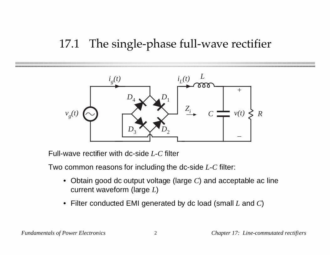
17.1 The single-phase full-wave rectifier
vg(t)
ig(t) iL(t)L
C R
+
v(t)
–
D1
D2D3
D4
Zi
Full-wave rectifier with dc-side L-C filter
Two common reasons for including the dc-side L-C filter:
• Obtain good dc output voltage (large C) and acceptable ac linecurrent waveform (large L)
• Filter conducted EMI generated by dc load (small L and C)
Fundamentals of Power Electronics 3 Chapter 17: Line-commutated rectifiers
17.1.1 Continuous conduction mode
vg(t)
ig(t)
THD = 29%
t10 ms 20 ms 30 ms 40 ms
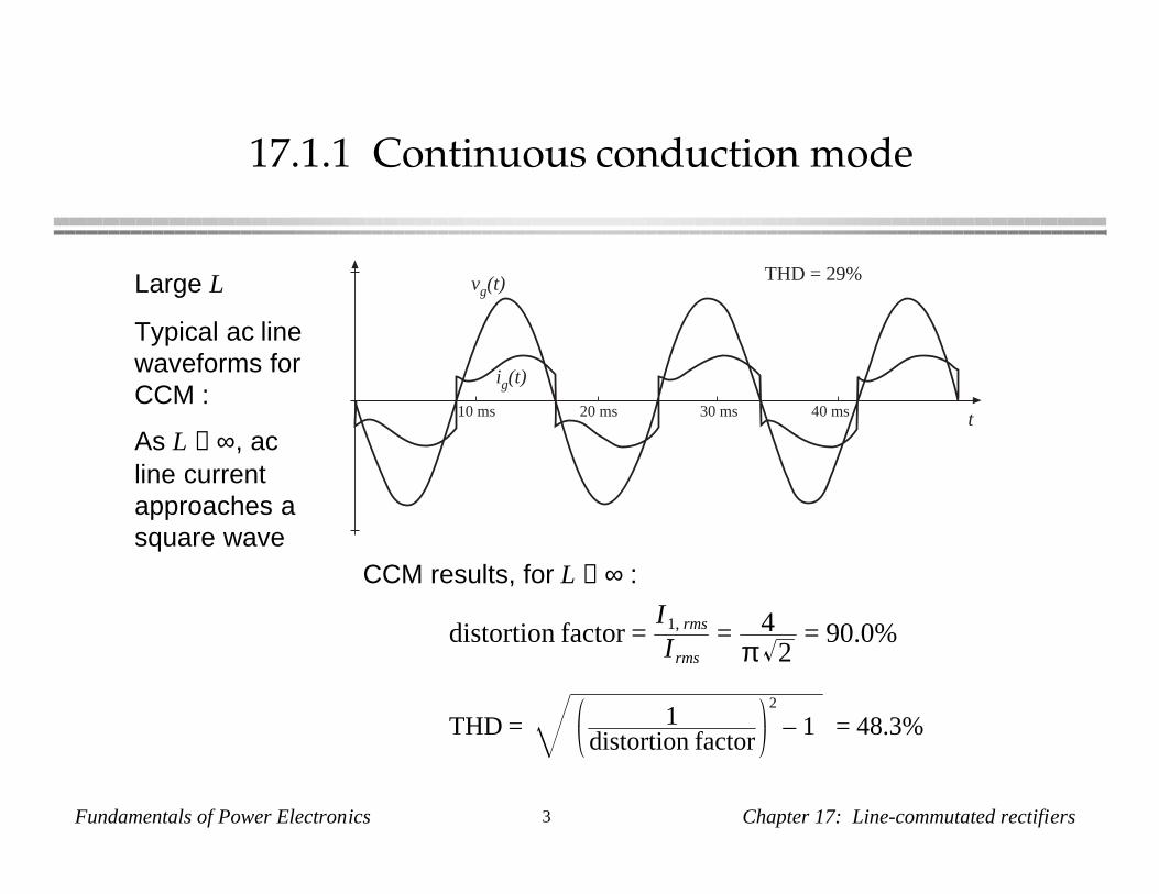
Large L
Typical ac linewaveforms forCCM :
As L →∞, acline currentapproaches asquare wave
distortion factor =I1, rms
Irms= 4
π 2= 90.0%
THD = 1distortion factor
2
– 1 = 48.3%
CCM results, for L →∞ :
Fundamentals of Power Electronics 4 Chapter 17: Line-commutated rectifiers
17.1.2 Discontinuous conduction mode
vg(t)
ig(t)
THD = 145%
t10 ms 20 ms 30 ms 40 ms
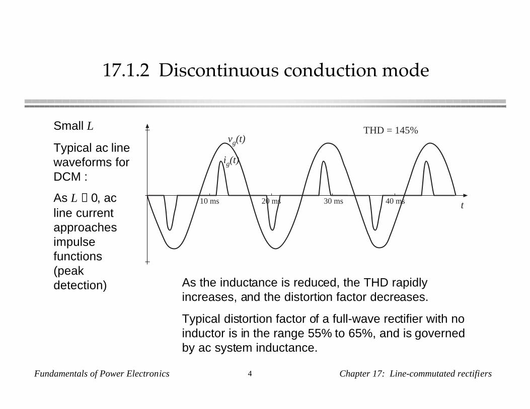
Small L
Typical ac linewaveforms forDCM :
As L →0, acline currentapproachesimpulsefunctions(peakdetection) As the inductance is reduced, the THD rapidly
increases, and the distortion factor decreases.
Typical distortion factor of a full-wave rectifier with noinductor is in the range 55% to 65%, and is governedby ac system inductance.
Fundamentals of Power Electronics 5 Chapter 17: Line-commutated rectifiers
17.1.3 Behavior when C is large
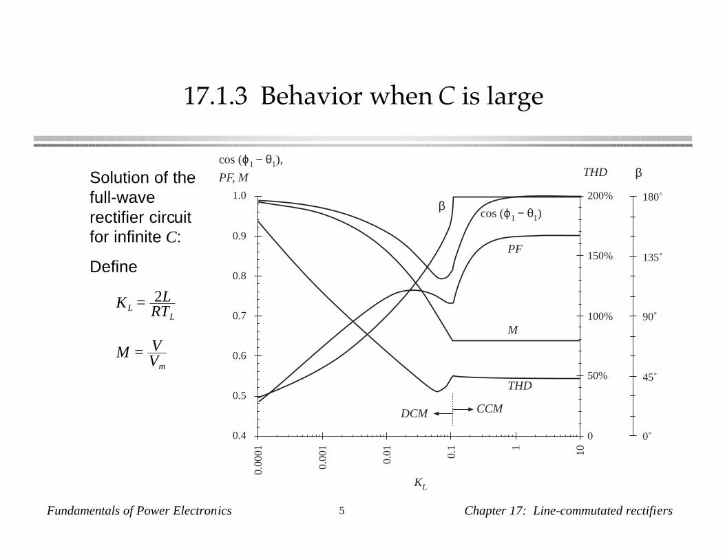
Solution of thefull-waverectifier circuitfor infinite C:
Define
KL = 2LRTL
M = VVm
0
50%
100%
150%
200%
THD
THD
M
PF
cos (ϕ1 − θ1)
0.4
0.5
0.6
0.7
0.8
0.9
1.0
PF, M
cos (ϕ1 − θ1),
KL
0.00
01
0.00
1
0.01 0.1 1 10
CCMDCM
0˚
45˚
90˚
135˚
180˚
β
β
Fundamentals of Power Electronics 6 Chapter 17: Line-commutated rectifiers
17.1.4 Minimizing THD when C is small
vg(t)
ig(t) iL(t)L
C R
+
v(t)
–
D1
D2D3
D4
Zi
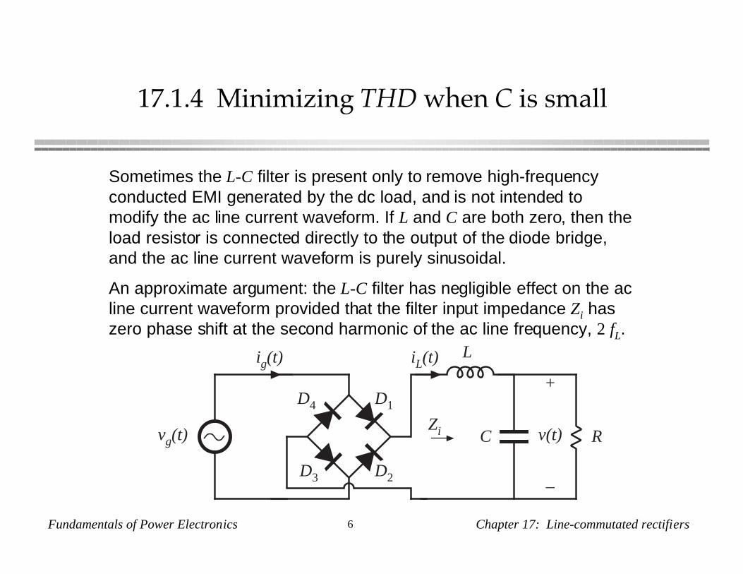
Sometimes the L-C filter is present only to remove high-frequencyconducted EMI generated by the dc load, and is not intended tomodify the ac line current waveform. If L and C are both zero, then theload resistor is connected directly to the output of the diode bridge,and the ac line current waveform is purely sinusoidal.
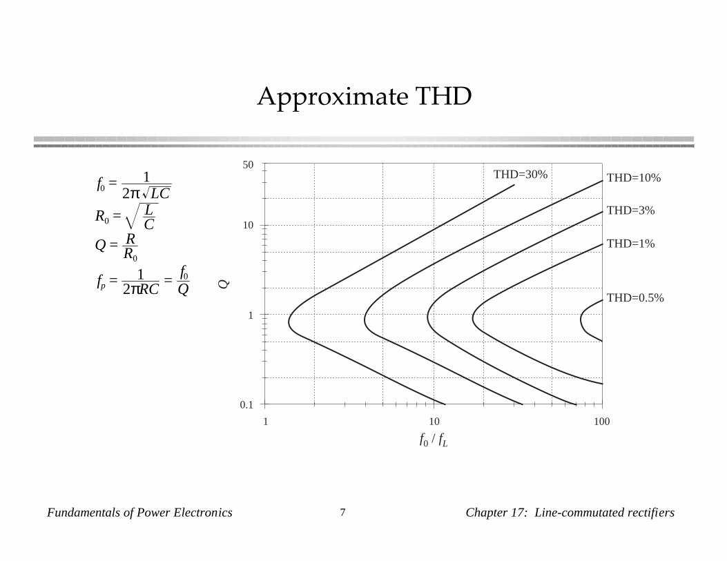
An approximate argument: the L-C filter has negligible effect on the acline current waveform provided that the filter input impedance Zi haszero phase shift at the second harmonic of the ac line frequency, 2 fL.
Fundamentals of Power Electronics 7 Chapter 17: Line-commutated rectifiers
Approximate THD
Q
THD=1%
THD=3%
THD=10%
THD=0.5%
THD=30%
f0 / fL
1 10 100
0.1
1
10
50
f0 = 12π LC
R0 = LC
Q = RR0
fp = 12πRC
=f0Q
Fundamentals of Power Electronics 8 Chapter 17: Line-commutated rectifiers
Example
vg(t)
ig(t)
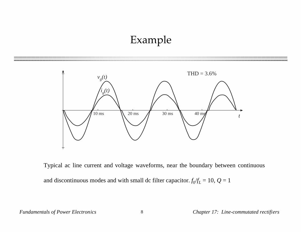
THD = 3.6%
t10 ms 20 ms 30 ms 40 ms
Typical ac line current and voltage waveforms, near the boundary between continuous
and discontinuous modes and with small dc filter capacitor. f0/fL = 10, Q = 1
Fundamentals of Power Electronics 9 Chapter 17: Line-commutated rectifiers
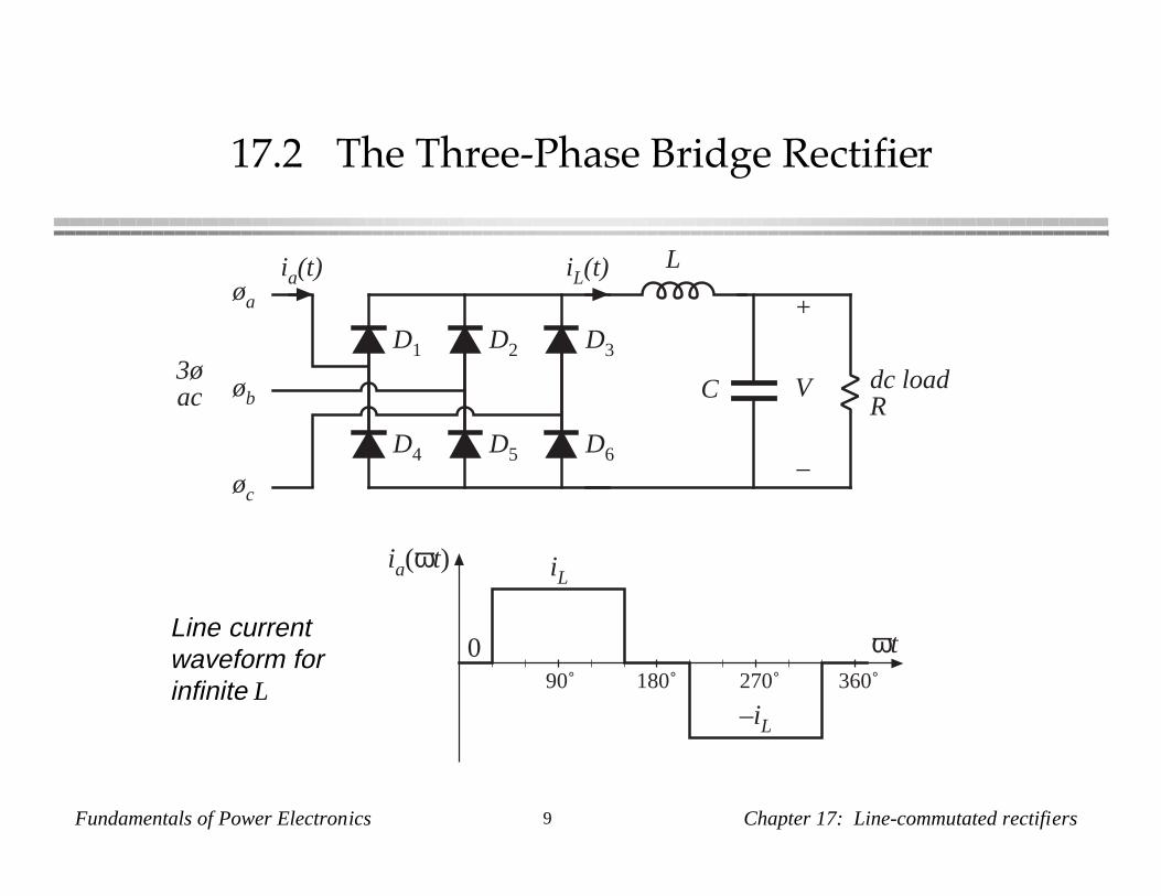
17.2 The Three-Phase Bridge Rectifier
LiL(t)
+
V
–
C dc loadR
øa
øb
øc
ia(t)
3øac
D1 D2 D3
D4 D5 D6
0
iL
–iL
90˚ 180˚ 270˚ 360˚
ia(ωt)
ωtLine currentwaveform forinfinite L
Fundamentals of Power Electronics 10 Chapter 17: Line-commutated rectifiers
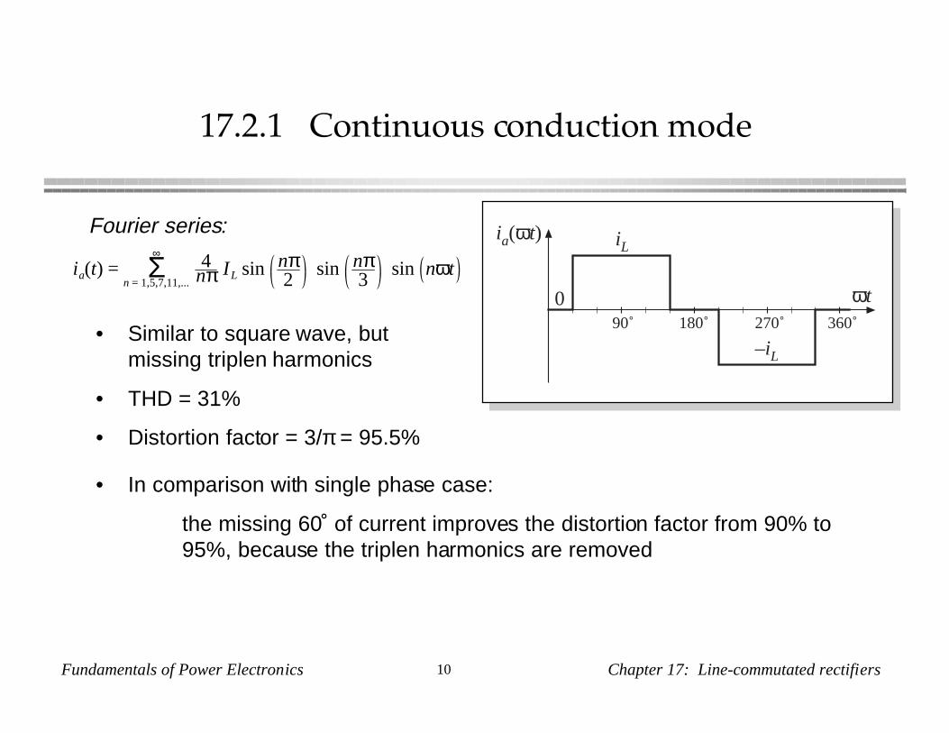
17.2.1 Continuous conduction mode
0
iL
–iL
90˚ 180˚ 270˚ 360˚
ia(ωt)
ωtia(t) = 4
nπ IL sin nπ2
sin nπ3
sin nωtΣn = 1,5,7,11,...
∞
Fourier series:
• Similar to square wave, butmissing triplen harmonics
• THD = 31%
• Distortion factor = 3/π = 95.5%
• In comparison with single phase case:
the missing 60˚ of current improves the distortion factor from 90% to95%, because the triplen harmonics are removed
Fundamentals of Power Electronics 11 Chapter 17: Line-commutated rectifiers
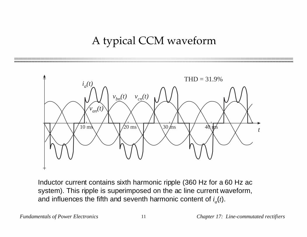
A typical CCM waveform
van(t)
ia(t)THD = 31.9%
t10 ms 20 ms 30 ms 40 ms
vbn(t) vcn(t)
Inductor current contains sixth harmonic ripple (360 Hz for a 60 Hz acsystem). This ripple is superimposed on the ac line current waveform,and influences the fifth and seventh harmonic content of ia(t).
Fundamentals of Power Electronics 12 Chapter 17: Line-commutated rectifiers
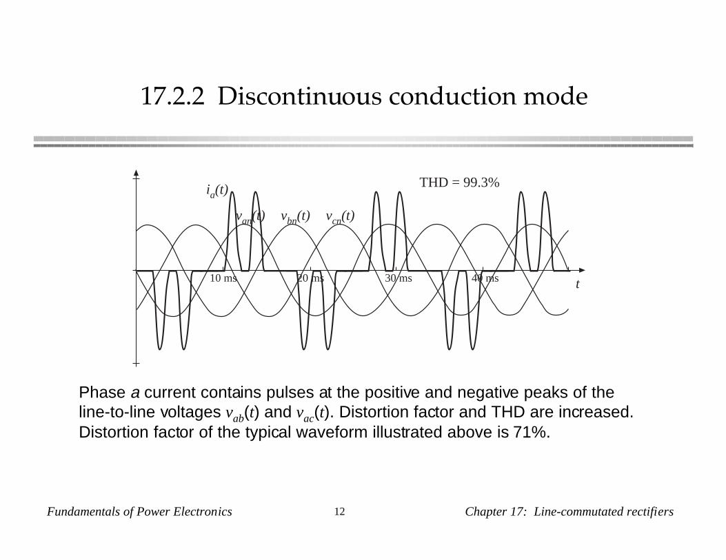
17.2.2 Discontinuous conduction mode
van(t)
ia(t)THD = 99.3%
t10 ms 20 ms 30 ms 40 ms
vbn(t) vcn(t)
Phase a current contains pulses at the positive and negative peaks of theline-to-line voltages vab(t) and vac(t). Distortion factor and THD are increased.Distortion factor of the typical waveform illustrated above is 71%.
Fundamentals of Power Electronics 13 Chapter 17: Line-commutated rectifiers
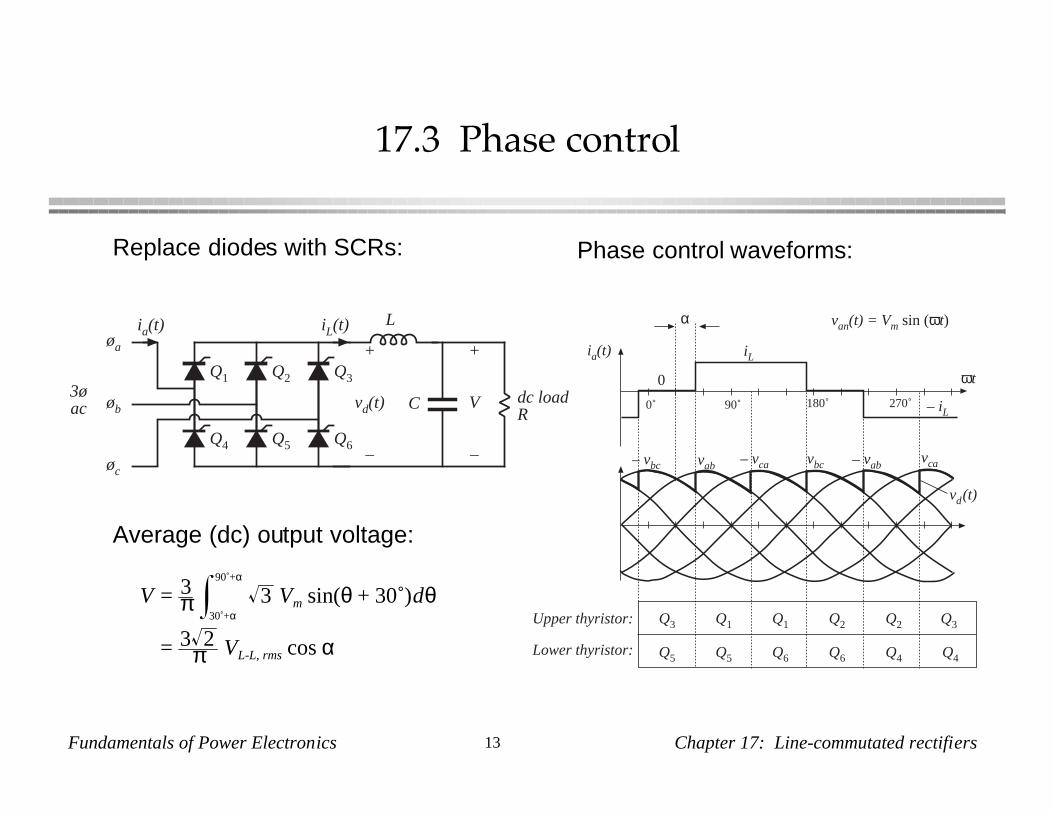
17.3 Phase control
LiL(t)
+
V
–
C dc loadR
øa
øb
øc
ia(t)
3øac
Q1 Q2 Q3
Q4 Q5 Q6
+
vd(t)
–
Q5 Q6 Q4Q5 Q6 Q4
Q1 Q2 Q3Q1Q3 Q2
0
α
Upper thyristor:
Lower thyristor:
90˚ 180˚ 270˚0˚
ωt
ia(t) iL
– iL
van(t) = Vm sin (ωt)
– vbc – vcavab vbc – vabvca
vd(t)
Replace diodes with SCRs: Phase control waveforms:
Average (dc) output voltage:
V = 3π 3 Vm sin(θ + 30˚)dθ
30˚+α
90˚+α
= 3 2π VL-L, rms cos α

Fundamentals of Power Electronics 14 Chapter 17: Line-commutated rectifiers
Dc output voltage vs. delay angle α
0 30 60 90 120 150 180
InversionRectification
α, degrees
VVL–L, rms
–1.5
–1
–0.5
0
0.5
1
1.5
V = 3π 3 Vm sin(θ + 30˚)dθ
30˚+α
90˚+α
= 3 2π VL-L, rms cos α
Fundamentals of Power Electronics 15 Chapter 17: Line-commutated rectifiers
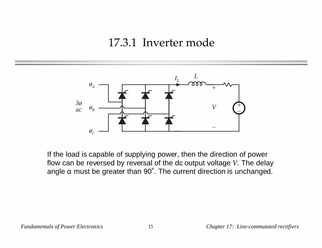
17.3.1 Inverter mode
LIL
+
V
–
øa
øb
øc
3øac
+–
If the load is capable of supplying power, then the direction of powerflow can be reversed by reversal of the dc output voltage V. The delayangle α must be greater than 90˚. The current direction is unchanged.
Fundamentals of Power Electronics 16 Chapter 17: Line-commutated rectifiers
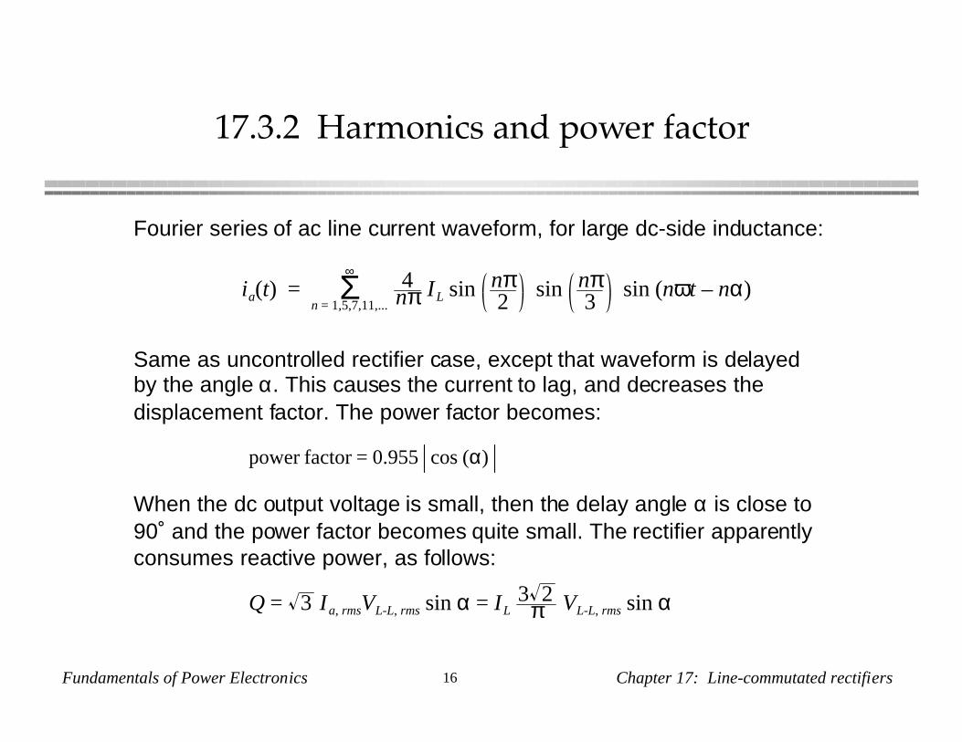
17.3.2 Harmonics and power factor
Fourier series of ac line current waveform, for large dc-side inductance:
ia(t) = 4nπ IL sin nπ
2sin nπ
3sin (nωt – nα)Σ
n = 1,5,7,11,...
∞
Same as uncontrolled rectifier case, except that waveform is delayedby the angle α. This causes the current to lag, and decreases thedisplacement factor. The power factor becomes:
power factor = 0.955 cos (α)
When the dc output voltage is small, then the delay angle α is close to90˚ and the power factor becomes quite small. The rectifier apparentlyconsumes reactive power, as follows:
Q = 3 Ia, rmsVL-L, rms sin α = IL3 2
π VL-L, rms sin α
Fundamentals of Power Electronics 17 Chapter 17: Line-commutated rectifiers
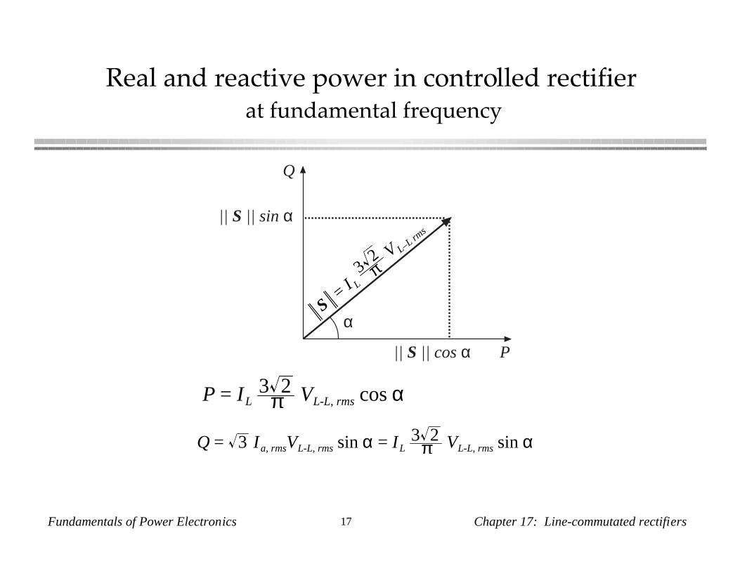
Real and reactive power in controlled rectifier at fundamental frequency
Q
P
|| S || sin α
|| S || cos α
αS
= I L
32π
V L–L rms
Q = 3 Ia, rmsVL-L, rms sin α = IL3 2
π VL-L, rms sin α
P = IL3 2
π VL-L, rms cos α
Fundamentals of Power Electronics 18 Chapter 17: Line-commutated rectifiers
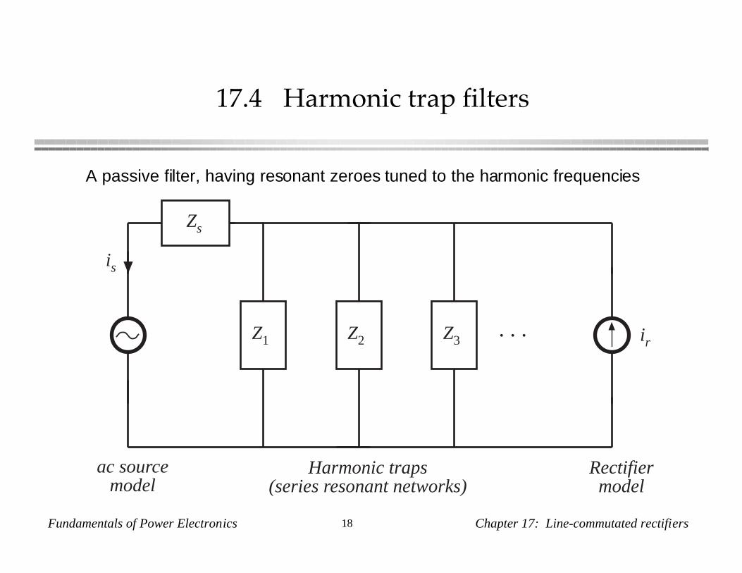
17.4 Harmonic trap filters
ir
is
Z1 Z2 Z3. . .
Zs
Rectifiermodel
ac sourcemodel
Harmonic traps(series resonant networks)
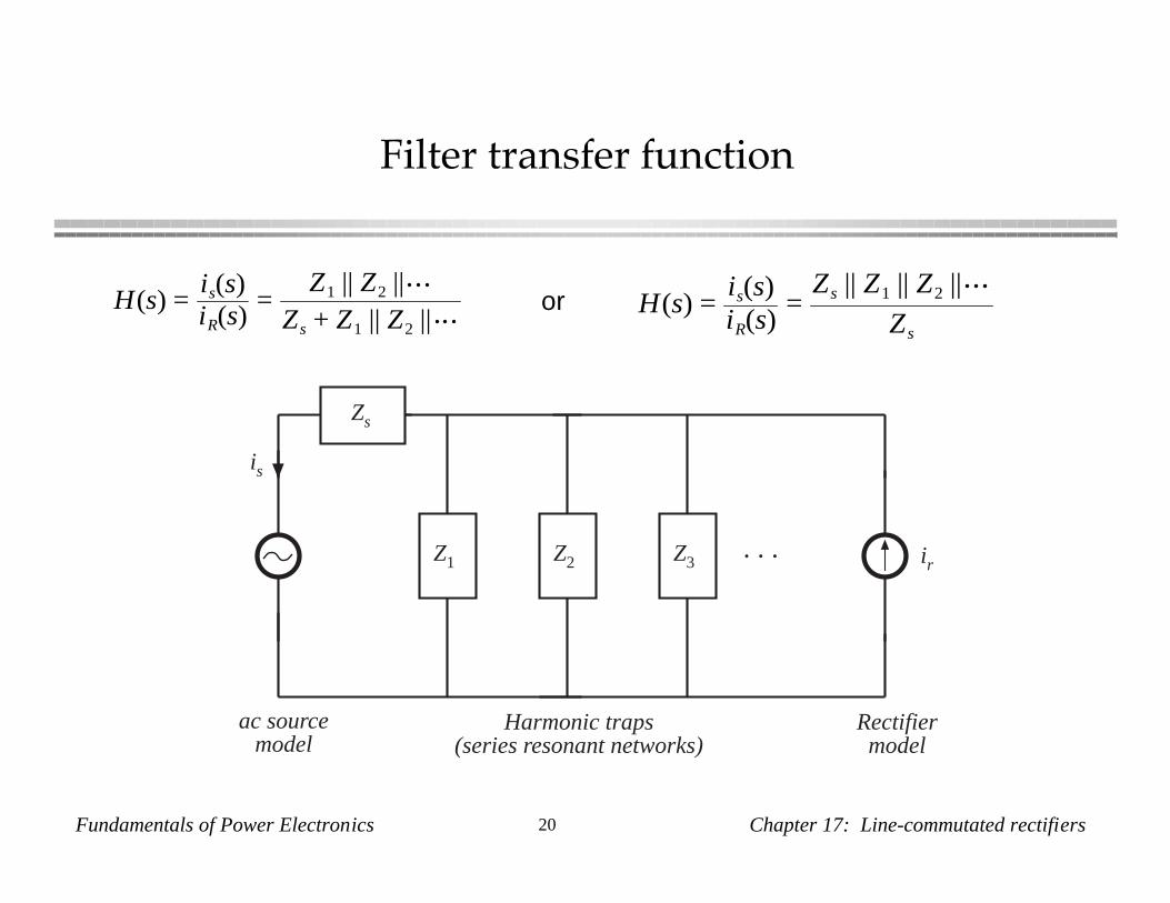
A passive filter, having resonant zeroes tuned to the harmonic frequencies
Fundamentals of Power Electronics 19 Chapter 17: Line-commutated rectifiers
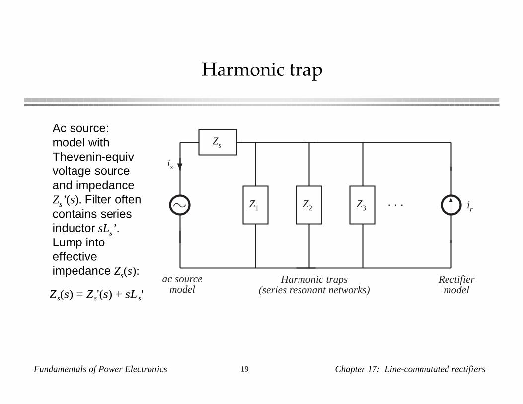
Harmonic trap
ir
is
Z1 Z2 Z3. . .
Zs
Rectifiermodel
ac sourcemodel
Harmonic traps(series resonant networks)Zs(s) = Zs'(s) + sLs'
Ac source:model withThevenin-equivvoltage sourceand impedanceZs’ (s). Filter oftencontains seriesinductor sLs’ .Lump intoeffectiveimpedance Zs(s):
Fundamentals of Power Electronics 20 Chapter 17: Line-commutated rectifiers
Filter transfer function
ir
is
Z1 Z2 Z3. . .
Zs
Rectifiermodel
ac sourcemodel
Harmonic traps(series resonant networks)
H(s) =is(s)iR(s)
=Z1 || Z2 ||
Zs + Z1 || Z2 ||H(s) =
is(s)iR(s)
=Zs || Z1 || Z2 ||
Zs
or
Fundamentals of Power Electronics 21 Chapter 17: Line-commutated rectifiers
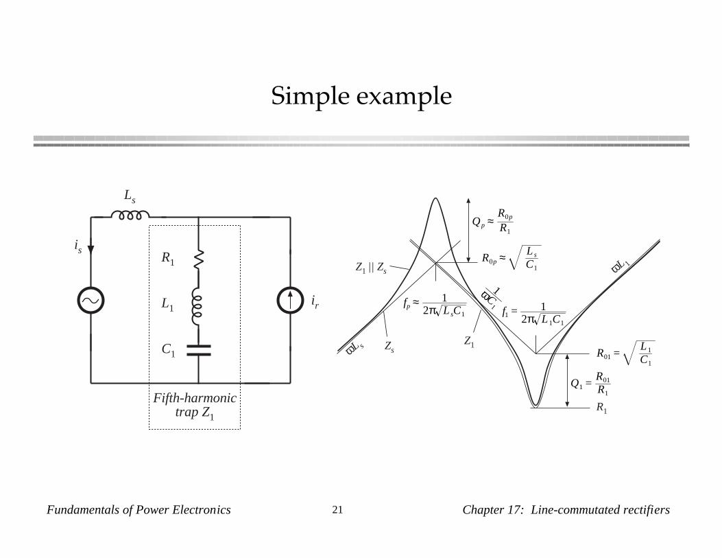
Simple example
R1
L1
C1
Fifth-harmonictrap Z1
Ls
ir
is
Q1 =R01
R1
fp ≈ 12π LsC1 f1 = 1
2π L 1C1
R1
ωL 1
ωL sZ1Zs
Z1 || Zs
1ωC1
R01 =L 1
C1
R0p ≈ Ls
C1
Qp ≈R0p
R1

Fundamentals of Power Electronics 22 Chapter 17: Line-commutated rectifiers
Simple example: transfer function
f1
fp
Q1
Qp
1
L 1
L 1 + Ls
– 40 dB/decade
• Series resonance: fifthharmonic trap
• Parallel resonance: C1and Ls
• Parallel resonancetends to increaseamplitude of thirdharmonic
• Q of parallelresonance is largerthan Q of seriesresonance

Fundamentals of Power Electronics 23 Chapter 17: Line-commutated rectifiers
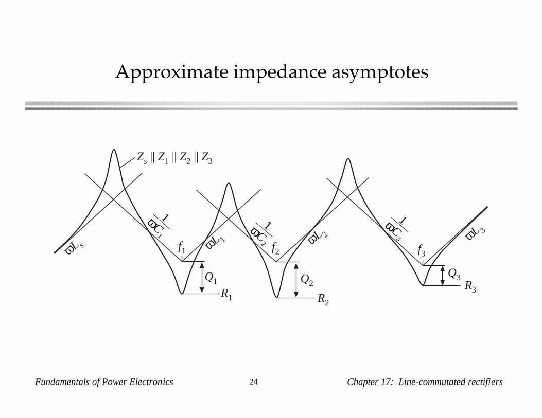
Example 2
Ls
ir
isR1
L1
C1
5th harmonictrap Z1
R2
L2
C2
7th harmonictrap Z2
R3
L3
C3
11th harmonictrap Z3
Fundamentals of Power Electronics 24 Chapter 17: Line-commutated rectifiers
Approximate impedance asymptotes
ωL s
R1
ωL 1f1
Q1
1ωC1
R2
ωL 2
f2
Q2 R3
ωL 3
f3
Q3
1ωC2
1ωC3
Zs || Z1 || Z2 || Z3
Fundamentals of Power Electronics 25 Chapter 17: Line-commutated rectifiers
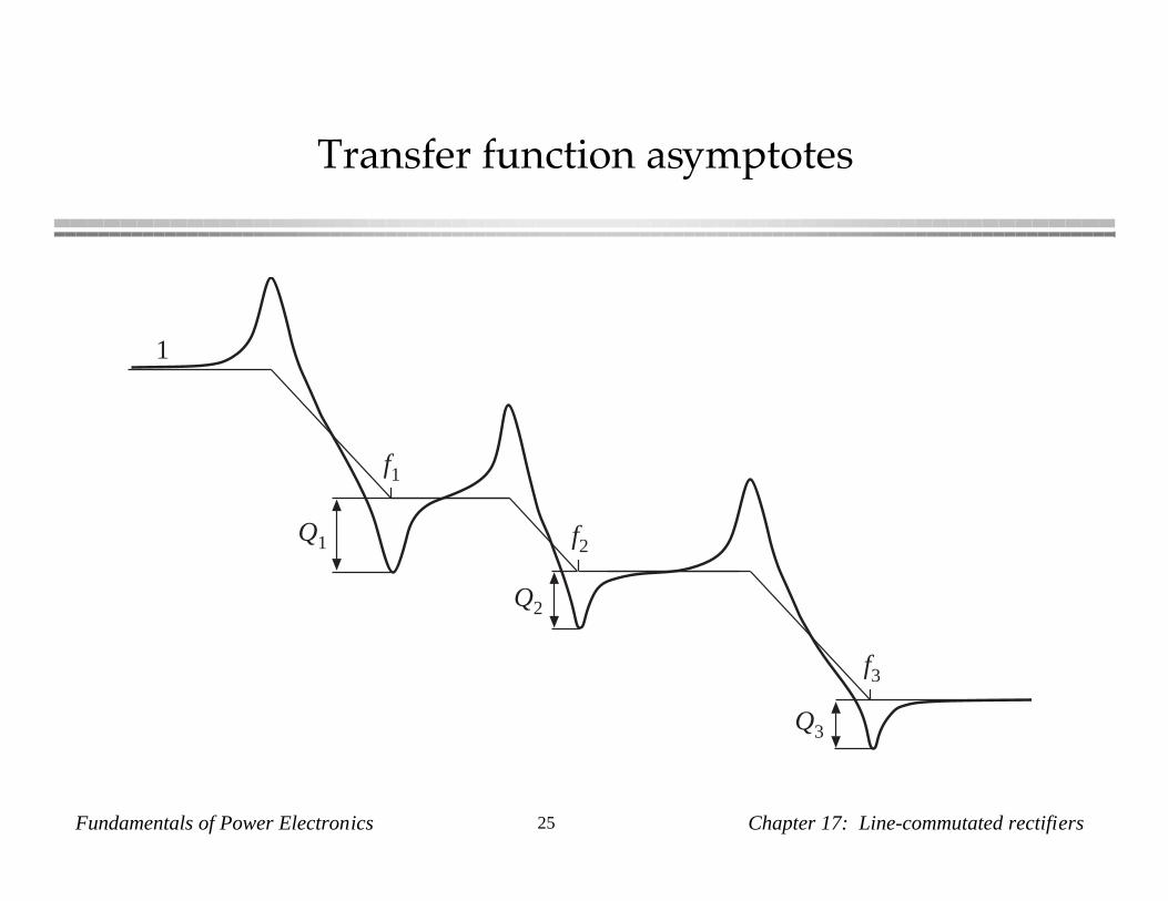
Transfer function asymptotes
f1
1
Q2
f2Q1
f3
Q3
Fundamentals of Power Electronics 26 Chapter 17: Line-commutated rectifiers
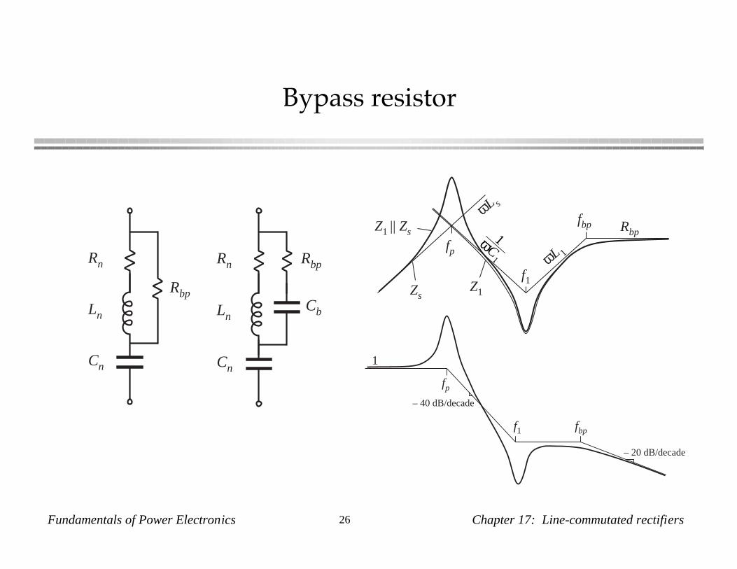
Bypass resistor
Rn
Ln
Cn
Rbp
Rn
Ln
Cn
Rbp
Cb
ωL 1
ωL s
Z1Zs
Z1 || Zs 1ωC1
fp
f1
Rbpfbp
f1
fp
1
– 40 dB/decade
fbp
– 20 dB/decade
Fundamentals of Power Electronics 27 Chapter 17: Line-commutated rectifiers
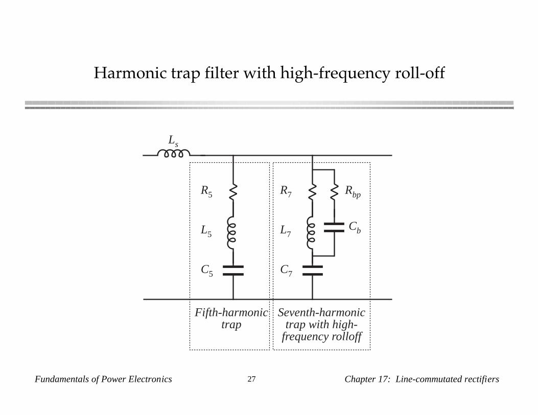
Harmonic trap filter with high-frequency roll-off
R7
L7
C7
Rbp
Cb
R5
L5
C5
Fifth-harmonictrap
Seventh-harmonictrap with high-
frequency rolloff
Ls
Fundamentals of Power Electronics 28 Chapter 17: Line-commutated rectifiers
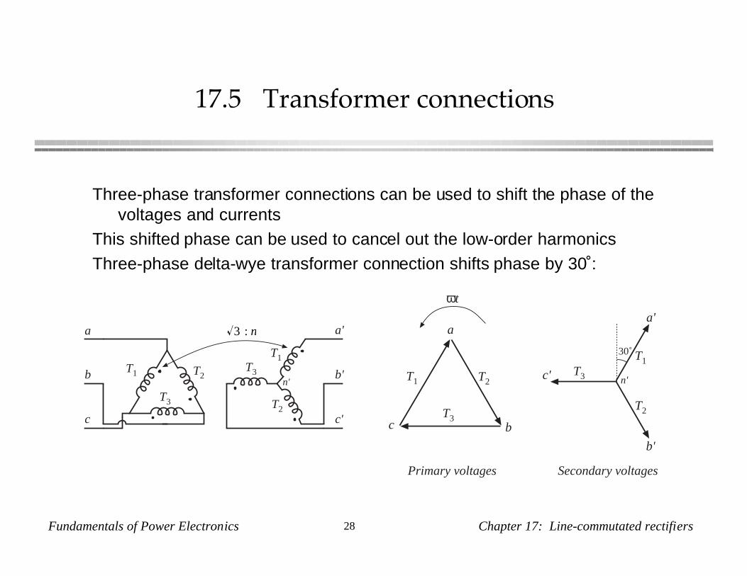
17.5 Transformer connections
Three-phase transformer connections can be used to shift the phase of thevoltages and currents
This shifted phase can be used to cancel out the low-order harmonics
Three-phase delta-wye transformer connection shifts phase by 30˚:
T1
T2
T3T1 T2
T3
a
b
c
a'
b'
c'
3 : n
n'
T1
T2
T3T1 T2
T3
a
bc
a'
b'
c' n'
30˚
Primary voltages Secondary voltages
ωt
Fundamentals of Power Electronics 29 Chapter 17: Line-commutated rectifiers
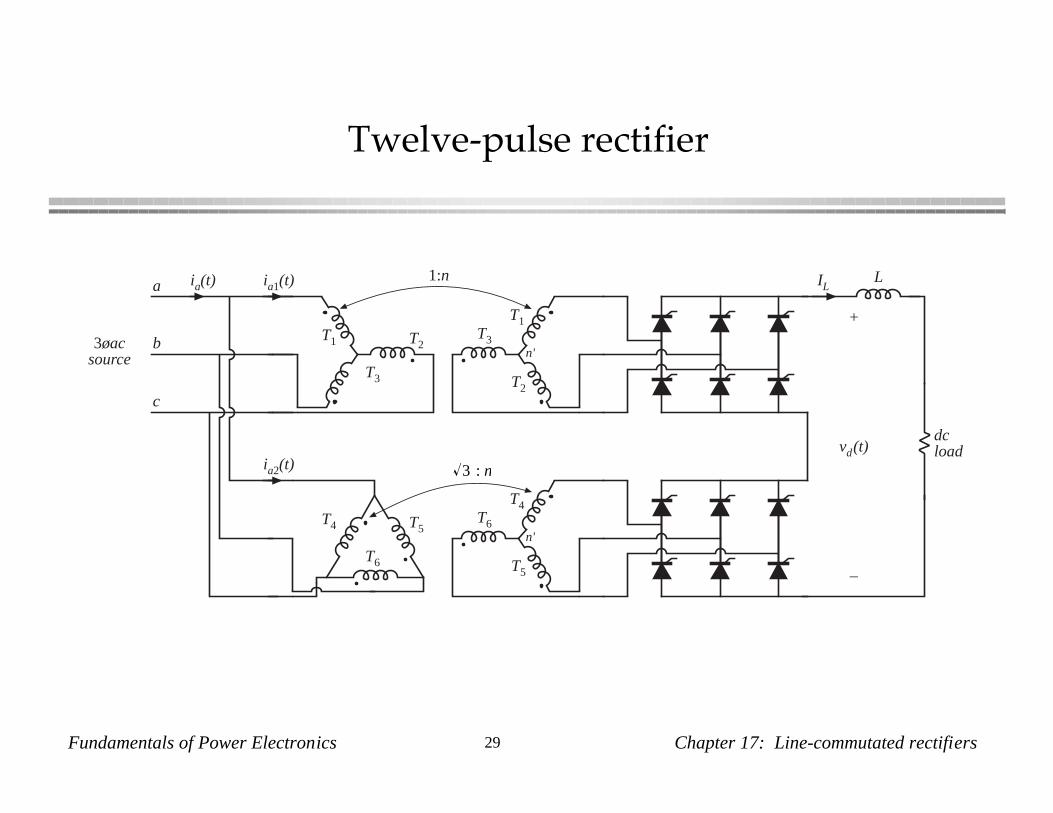
Twelve-pulse rectifier
T4
T5
T6T4 T5
T6
3 : n
n'
T1
T2
T3T1 T2
T3
a
b
c
n'
1:n LIL
+
vd(t)
–
dcload
3øacsource
ia1(t)
ia2(t)
ia(t)
Fundamentals of Power Electronics 30 Chapter 17: Line-commutated rectifiers
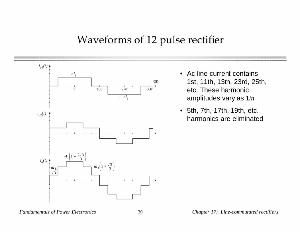
Waveforms of 12 pulse rectifier
ia1(t)
ia2(t)
ia(t)
90˚ 180˚ 270˚ 360˚
nIL
– nIL
nIL3
nI L 1 + 2 33
nI L 1 + 33
ωt
• Ac line current contains1st, 11th, 13th, 23rd, 25th,etc. These harmonicamplitudes vary as 1/n
• 5th, 7th, 17th, 19th, etc.harmonics are eliminated

Fundamentals of Power Electronics 31 Chapter 17: Line-commutated rectifiers
Rectifiers with high pulse number
Eighteen-pulse rectifier:
• Use three six-pulse rectifiers
• Transformer connections shift phase by 0˚, +20˚, and –20˚
• No 5th, 7th, 11th, 13th harmonics
Twenty-four-pulse rectifier
• Use four six-pulse rectifiers
• Transformer connections shift phase by 0˚, 15˚, –15˚, and 30˚
• No 5th, 7th, 11th, 13th, 17th, or 19th harmonics
If p is pulse number, then rectifier produces line current harmonics ofnumber n = pk ± 1, with k = 0, 1, 2, ...