Embed Size (px)
Citation preview
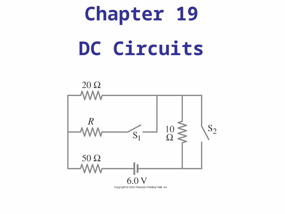
Chapter 19
DC Circuits
Objective: The students will be able to:
Describe the basic operation of a galvanometer and calculate the resistance which must be added to convert a galvanometer into an ammeter or a voltmeter.
19.7 Electric Hazards
Even very small currents – 10 to 100 mA can be dangerous, disrupting the nervous system. Larger currents may also cause burns.
Household voltage can be lethal if you are wet and in good contact with the ground. Be careful!
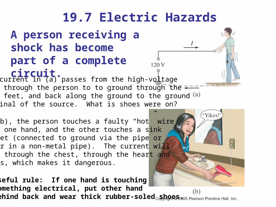
19.7 Electric HazardsA person receiving a shock has become part of a complete circuit.
The current in (a) passes from the high-voltagewire through the person to to ground through thebare feet, and back along the ground to the ground terminal of the source. What is shoes were on?
In (b), the person touches a faulty “hot” wirewith one hand, and the other touches a sinkfaucet (connected to ground via the pipe or water in a non-metal pipe). The current willpass through the chest, through the heart andlungs, which makes it dangerous.
Useful rule: If one hand is touching something electrical, put other handbehind back and wear thick rubber-soled shoes.
19.7 Electric Hazards
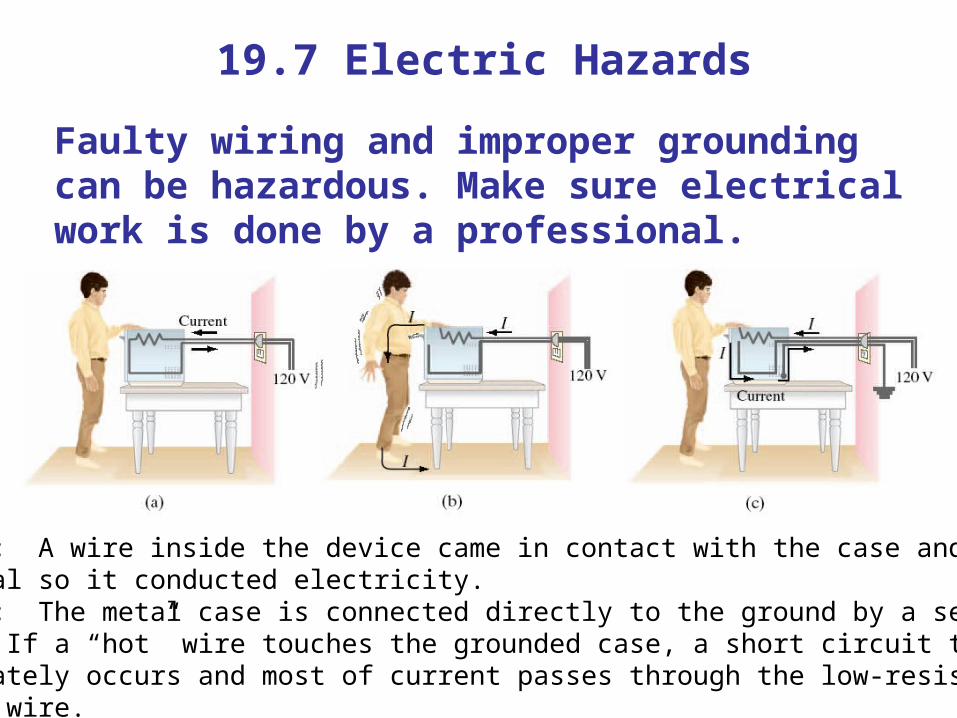
Faulty wiring and improper grounding can be hazardous. Make sure electrical work is done by a professional.
Case b: A wire inside the device came in contact with the case and the caseis metal so it conducted electricity. Case c: The metal case is connected directly to the ground by a separatewire. If a “hot” wire touches the grounded case, a short circuit to groundimmediately occurs and most of current passes through the low-resistanceground wire.
19.7 Electric Hazards
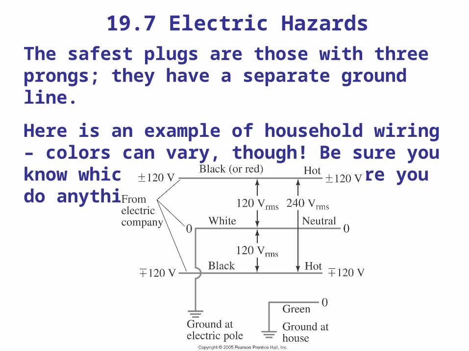
The safest plugs are those with three prongs; they have a separate ground line.
Here is an example of household wiring – colors can vary, though! Be sure you know which is the hot wire before you do anything.
19.8 Ammeters and Voltmeters
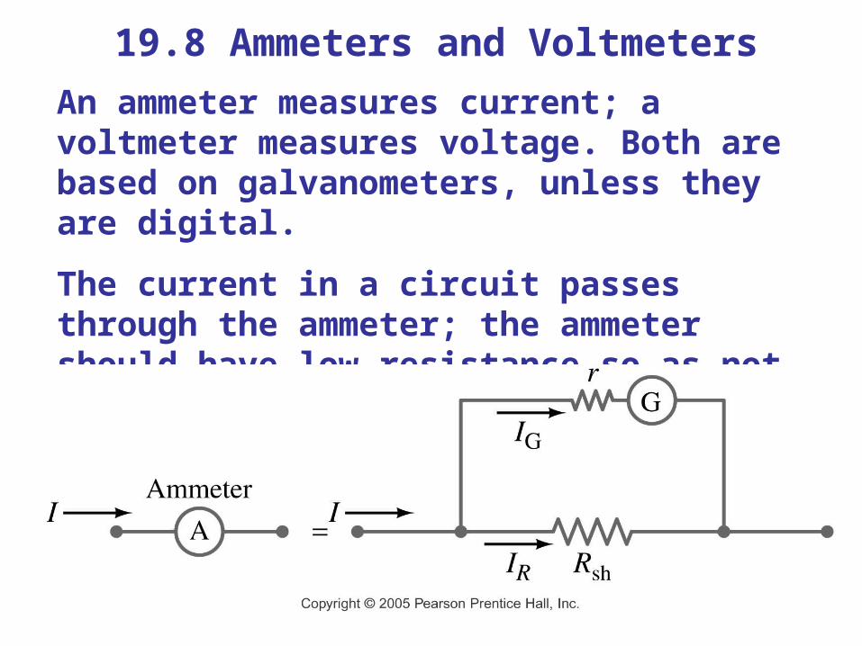
An ammeter measures current; a voltmeter measures voltage. Both are based on galvanometers, unless they are digital.
The current in a circuit passes through the ammeter; the ammeter should have low resistance so as not to affect the current.
8
Galvanometer
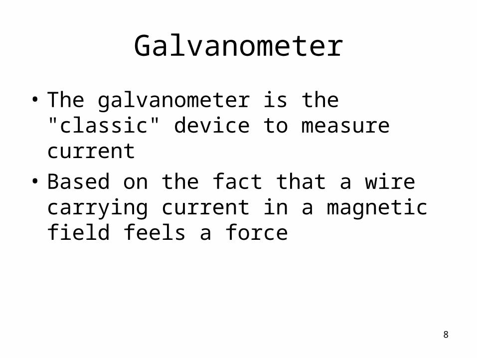
• The galvanometer is the "classic" device to measure current
• Based on the fact that a wire carrying current in a magnetic field feels a force
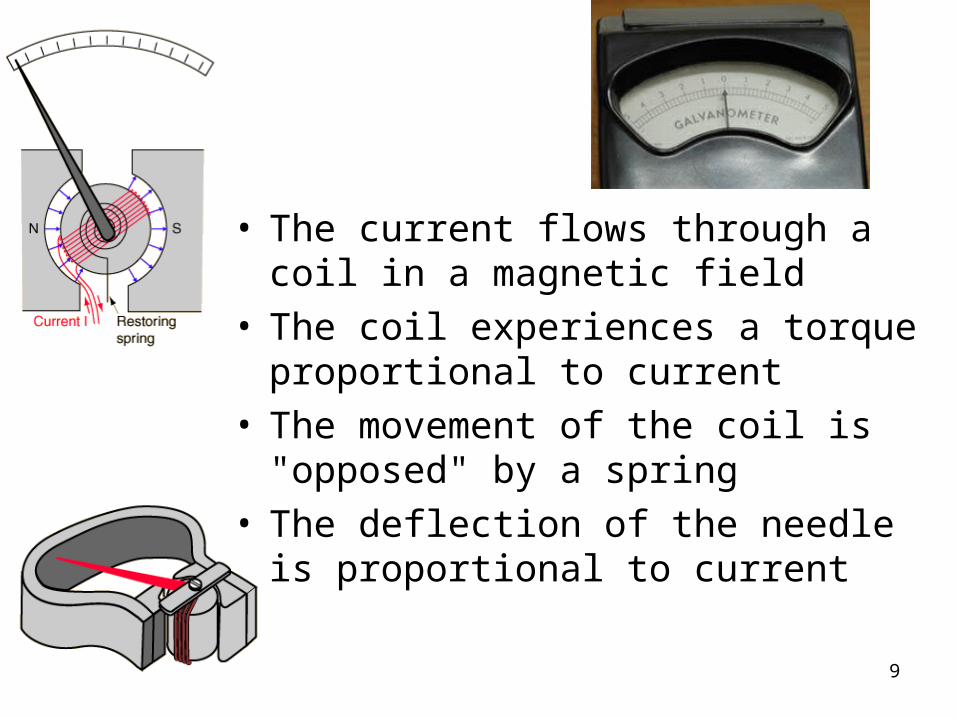
9
• The current flows through a coil in a magnetic field
• The coil experiences a torque proportional to current
• The movement of the coil is "opposed" by a spring
• The deflection of the needle is proportional to current
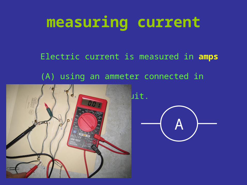
measuring current
Electric current is measured in amps (A)
using an ammeter connected in series in
the circuit.
A
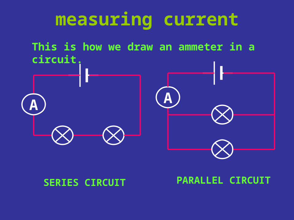
measuring current
A A
This is how we draw an ammeter in a circuit.
SERIES CIRCUIT PARALLEL CIRCUIT
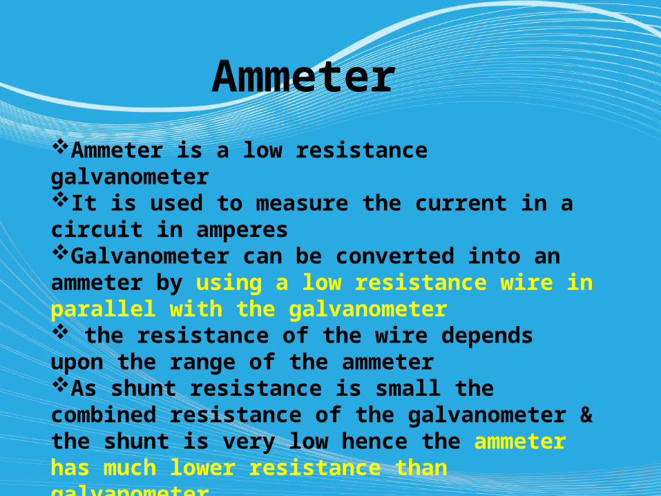
Ammeter Ammeter is a low resistance galvanometerIt is used to measure the current in a circuit in amperesGalvanometer can be converted into an ammeter by using a low resistance wire in parallel with the galvanometer the resistance of the wire depends upon the range of the ammeter As shunt resistance is small the combined resistance of the galvanometer & the shunt is very low hence the ammeter has much lower resistance than galvanometerAn ideal ammeter has zero resistance
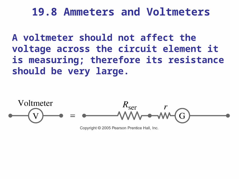
19.8 Ammeters and Voltmeters
A voltmeter should not affect the voltage across the circuit element it is measuring; therefore its resistance should be very large.
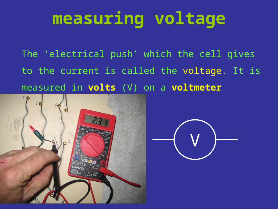
measuring voltage
The ‘electrical push’ which the cell gives to the
current is called the voltage. It is measured in
volts (V) on a voltmeter
V
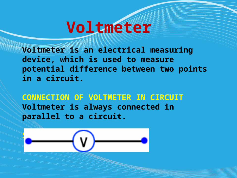
Voltmeter Voltmeter is an electrical measuring device, which is used to measure potential difference between two points in a circuit. CONNECTION OF VOLTMETER IN CIRCUITVoltmeter is always connected in parallel to a circuit. SYMBOL
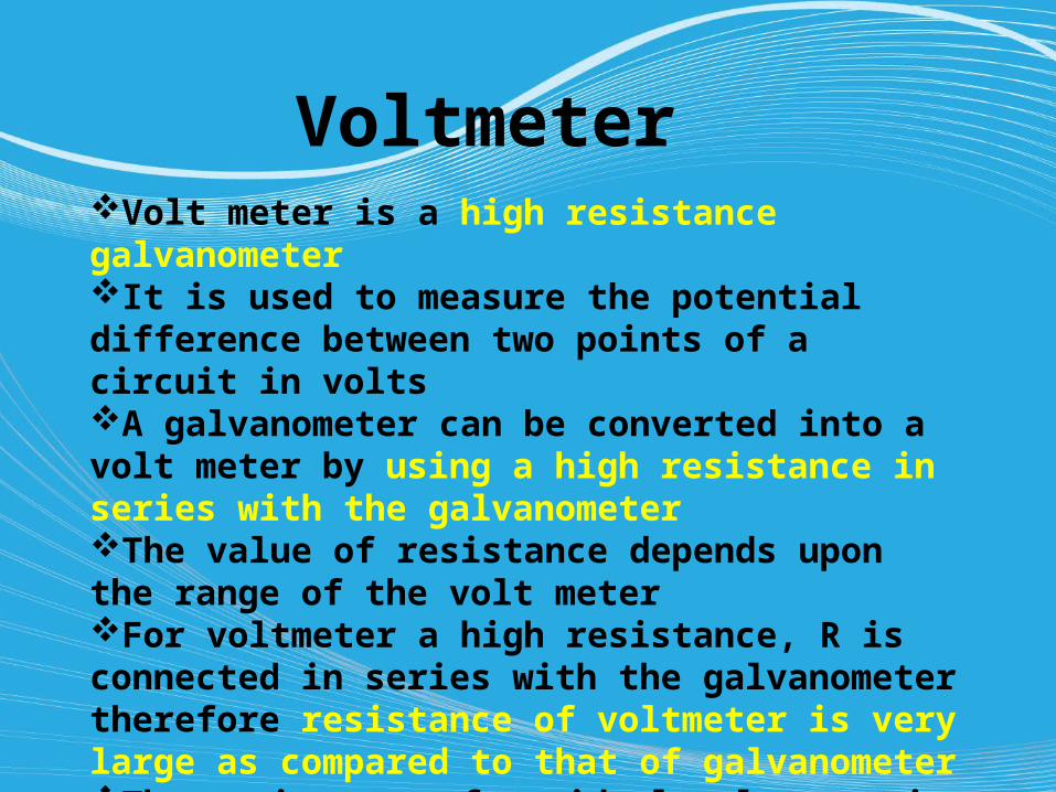
Voltmeter Volt meter is a high resistance galvanometerIt is used to measure the potential difference between two points of a circuit in voltsA galvanometer can be converted into a volt meter by using a high resistance in series with the galvanometerThe value of resistance depends upon the range of the volt meterFor voltmeter a high resistance, R is connected in series with the galvanometer therefore resistance of voltmeter is very large as compared to that of galvanometerThe resistance of an ideal voltmeter is infinity
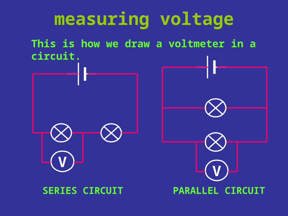
measuring voltage
V
This is how we draw a voltmeter in a circuit.
SERIES CIRCUIT PARALLEL CIRCUIT
V
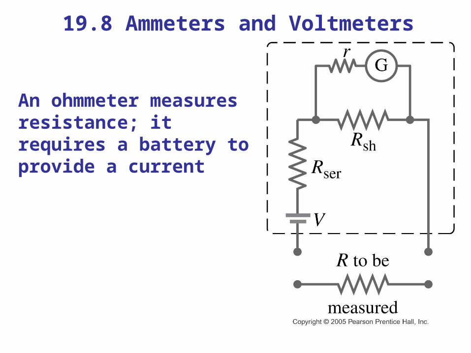
19.8 Ammeters and Voltmeters
An ohmmeter measures resistance; it requires a battery to provide a current
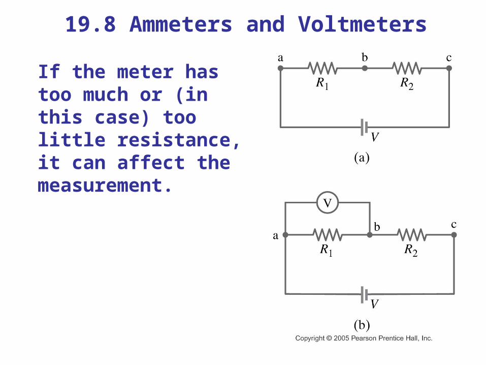
19.8 Ammeters and Voltmeters
If the meter has too much or (in this case) too little resistance, it can affect the measurement.
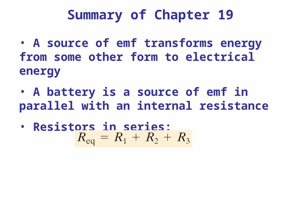
Summary of Chapter 19
• A source of emf transforms energy from some other form to electrical energy
• A battery is a source of emf in parallel with an internal resistance
• Resistors in series:
Summary of Chapter 19
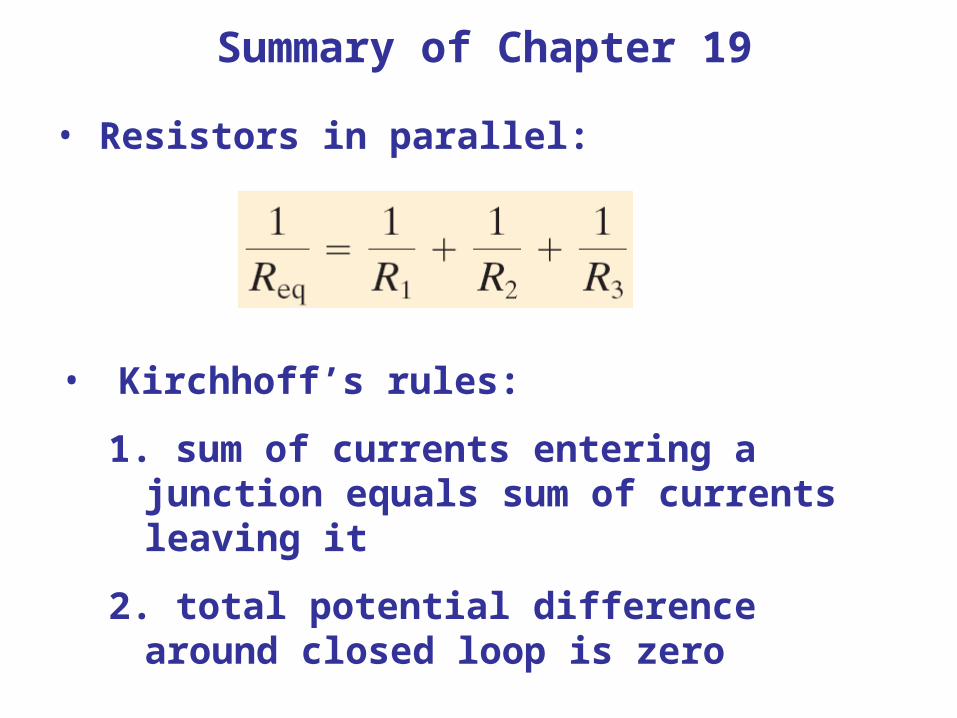
• Resistors in parallel:
• Kirchhoff’s rules:
1. sum of currents entering a junction equals sum of currents leaving it
2. total potential difference around closed loop is zero

Summary of Chapter 19
• Capacitors in parallel:
• Capacitors in series:
Summary of Chapter 19
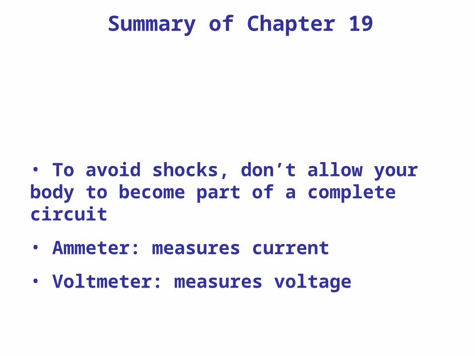
• To avoid shocks, don’t allow your body to become part of a complete circuit
• Ammeter: measures current
• Voltmeter: measures voltage

Closure:
Kahoot: 19-7 and 19-8