Embed Size (px)
Citation preview
ELECTRICAL POWER XL-2 AIRPLANE
P/N 135A-970-100 Chapter 24 REVISION E Page 1 of 64
CHAPTER 24
ELECTRICAL POWER
ELECTRICAL POWER XL-2 AIRPLANE
Chapter 24 P/N 135A-970-100 Page 2 of 64 REVISION D
Copyright © 2011 All rights reserved. The information contained herein is proprietary to Liberty Aerospace, Incorporated. It is prohibited to reproduce or transmit in any form or by any means, electronic or mechanical, including photocopying, recording, or use of any information storage and retrieval system, any portion of this document without express written permission of Liberty Aerospace Incorporated.
ELECTRICAL POWER XL-2 AIRPLANE
P/N 135A-970-100 Chapter 24 REVISION E Page 3 of 64
Table of Contents SECTION 24-00 GENERAL 5 SECTION 24-10 ALTERNATOR BELT DRIVE 9
SECTION 10-01 PERIODIC MAINTENANCE 10 SECTION 10-02 ALTERNATOR BELT PROCEDURES 10
ALTERNATOR BELT REMOVAL 11 ALTERNATOR BELT INSTALLATION 12 ALTERNATOR BELT TENSIONING 13 ALTERNATOR BELT OPERATION CHECK AND INSPECTION 14
SECTION 10-03 ALTERNATOR BELT TROUBLESHOOTING GUIDE 15 SECTION 24-30 DC GENERATION 17
SECTION 30-01 ALTERNATOR 17 SECTION 30-02 PERIODIC MAINTENANCE 17 SECTION 30-03 ALTERNATOR PROCEDURES 17
ALTERNATOR REMOVAL 18 ALTERNATOR INSTALLATION 19 ALTERNATOR FUSE F3 REPLACEMENT 20 ALTERNATOR OPERATION CHECK AND INSPECTION 22
SECTION 30-04 ALTERNATOR TROUBLESHOOTING GUIDE 23 SECTION 30-05 ALTERNATOR CONTROL UNIT (ACU) 24 SECTION 30-06 PERIODIC MAINTENANCE 24 SECTION 30-07 ALTERNATOR CONTROL UNIT (ACU) PROCEDURES 24
ALTERNATOR CONTROL UNIT (ACU) REMOVAL 25 ALTERNATOR CONTROL UNIT (ACU) INSTALLATION 26 ALTERNATOR CONTROL UNIT (ACU) OPERATION CHECK AND INSPECTION 27
SECTION 30-08 ACU TROUBLESHOOTING GUIDE 29 SECTION 30-09 BATTERIES 30 SECTION 30-10 PRIMARY BATTERY 30 SECTION 30-11 PERIODIC MAINTENANCE 31 SECTION 30-12 PRIMARY BATTERY PROCEDURES 31
PRIMARY BATTERY REMOVAL 32 PRIMARY BATTERY INSTALLATION 33 PRIMARY BATTERY OPERATION CHECK AND INSPECTION 35
SECTION 30-13 PRIMARY BATTERY TROUBLESHOOTING GUIDE 37 SECTION 30-14 SECONDARY BATTERY 38 SECTION 30-15 PERIODIC MAINTENANCE 39 SECTION 30-16 SECONDARY BATTERY PROCEDURES 39
SECONDARY BATTERY REMOVAL 40 SECONDARY BATTERY INSTALLATION 41 SECONDARY BATTERY OPERATIONAL CHECK AND INSPECTION 42
SECTION 30-17 SECONDARY BATTERY TROUBLESHOOTING GUIDE 43
ELECTRICAL POWER XL-2 AIRPLANE
Chapter 24 P/N 135A-970-100 Page 4 of 64 REVISION E
SECTION 24-60 DC ELECTRICAL LOAD DISTRIBUTION 45
SECTION 60-01 DC POWER DISTRIBUTION 45 SECTION 60-02 PERIODIC MAINTENANCE 45 SECTION 60-03 CIRCUIT BREAKER AND MASTER RELAY PROCEDURES 45
CIRCUIT BREAKER REMOVAL 46 CIRCUIT BREAKER INSTALLATION 48 MASTER RELAY REMOVAL 49 MASTER RELAY INSTALLATION 51 CIRCUIT BREAKER AND MASTER RELAY OPERATION CHECK AND INSPECTION 53
SECTION 60-04 MASTER RELAY TROUBLESHOOTING GUIDE 55 SECTION 60-05 AVIONICS POWER DISTRIBUTION 57 SECTION 60-06 CIRCUIT BREAKER REMOVAL AND INSTALLATION 58 SECTION 60-07 PERIODIC MAINTENANCE 58 SECTION 60-08 AVIONICS POWER DISTRIBUTION PROCEDURES 58
AVIONICS MASTER RELAY REMOVAL 59 AVIONICS MASTER RELAY INSTALLATION 61 AVIONICS POWER DISTRIBUTION OPERATION CHECK AND INSPECTION 62
SECTION 60-09 AVIONICS POWER SUBSYSTEM TROUBLESHOOTING GUIDE 64
ELECTRICAL POWER XL-2 AIRPLANE
P/N 135A-970-100 24-00 REVISION E Page 5 of 64
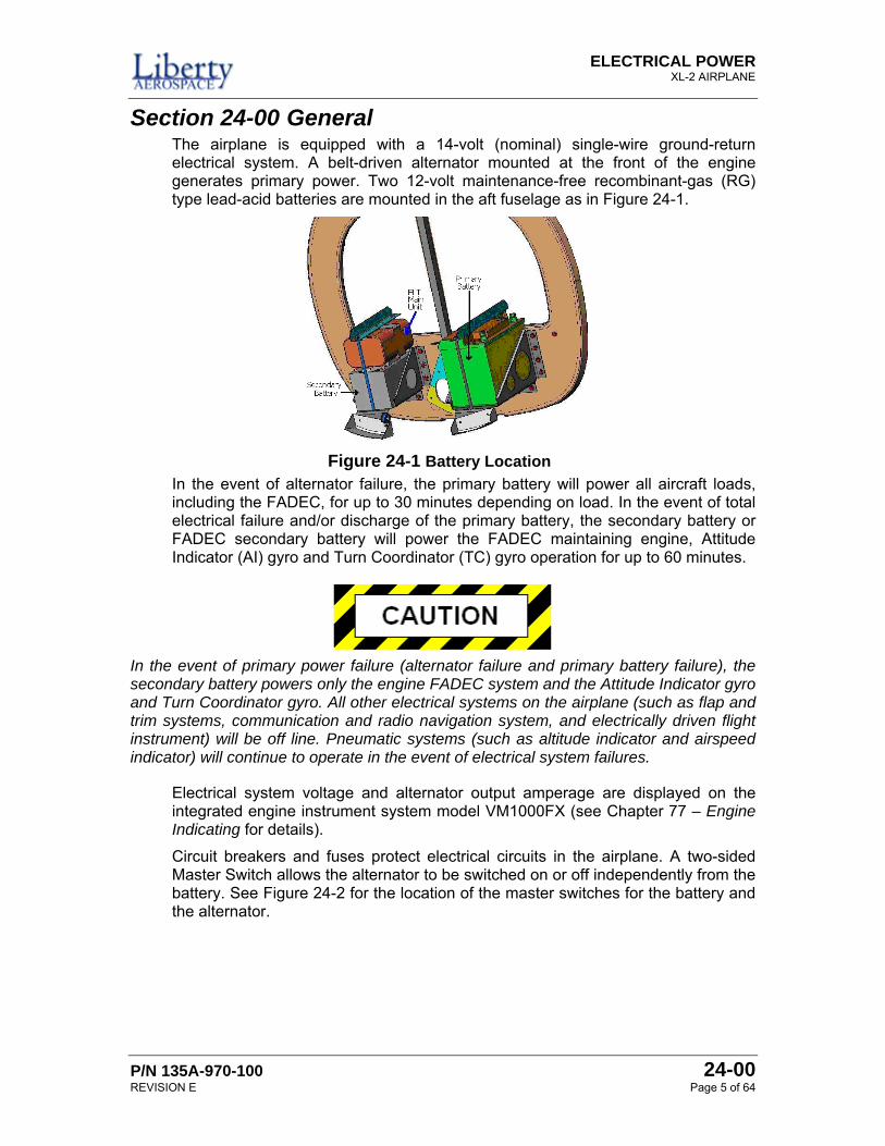
Section 24-00 General The airplane is equipped with a 14-volt (nominal) single-wire ground-return electrical system. A belt-driven alternator mounted at the front of the engine generates primary power. Two 12-volt maintenance-free recombinant-gas (RG) type lead-acid batteries are mounted in the aft fuselage as in Figure 24-1.
In the event of alternator failure, the primary battery will power all aircraft loads, including the FADEC, for up to 30 minutes depending on load. In the event of total electrical failure and/or discharge of the primary battery, the secondary battery or FADEC secondary battery will power the FADEC maintaining engine, Attitude Indicator (AI) gyro and Turn Coordinator (TC) gyro operation for up to 60 minutes.
In the event of primary power failure (alternator failure and primary battery failure), the secondary battery powers only the engine FADEC system and the Attitude Indicator gyro and Turn Coordinator gyro. All other electrical systems on the airplane (such as flap and trim systems, communication and radio navigation system, and electrically driven flight instrument) will be off line. Pneumatic systems (such as altitude indicator and airspeed indicator) will continue to operate in the event of electrical system failures.
Electrical system voltage and alternator output amperage are displayed on the integrated engine instrument system model VM1000FX (see Chapter 77 – Engine Indicating for details).
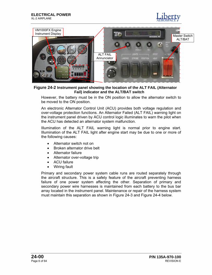
Circuit breakers and fuses protect electrical circuits in the airplane. A two-sided Master Switch allows the alternator to be switched on or off independently from the battery. See Figure 24-2 for the location of the master switches for the battery and the alternator.
Figure 24-1 Battery Location
ELECTRICAL POWER XL-2 AIRPLANE
24-00 P/N 135A-970-100 Page 6 of 64 REVISION E
However, the battery must be in the ON position to allow the alternator switch to be moved to the ON position.
An electronic Alternator Control Unit (ACU) provides both voltage regulation and over-voltage protection functions. An Alternator Failed (ALT FAIL) warning light on the instrument panel driven by ACU control logic illuminates to warn the pilot when the ACU has detected an alternator system malfunction.
Illumination of the ALT FAIL warning light is normal prior to engine start. Illumination of the ALT FAIL light after engine start may be due to one or more of the following causes:
• Alternator switch not on • Broken alternator drive belt • Alternator failure • Alternator over-voltage trip • ACU failure • Wiring fault
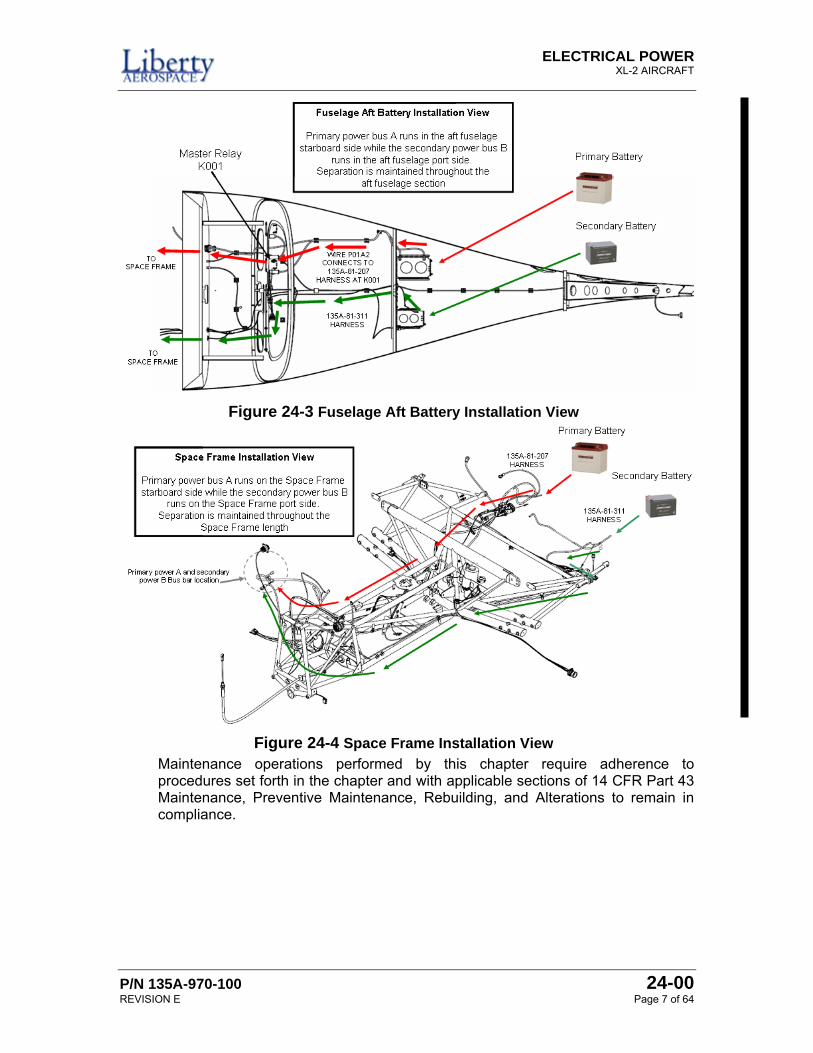
Primary and secondary power system cable runs are routed separately through the aircraft structure. This is a safety feature of the aircraft preventing harness failure of one power system affecting the other. Separation of primary and secondary power wire harnesses is maintained from each battery to the bus bar array located in the instrument panel. Maintenance or repair of the harness system must maintain this separation as shown in Figure 24-3 and Figure 24-4 below.
Figure 24-2 Instrument panel showing the location of the ALT FAIL (Alternator Fail) indicator and the ALT/BAT switch
VM1000FX Engine Instrument Display
ALT FAIL Annunciator
Master SwitchALT/BAT
ELECTRICAL POWER XL-2 AIRCRAFT
P/N 135A-970-100 24-00 REVISION E Page 7 of 64
Maintenance operations performed by this chapter require adherence to procedures set forth in the chapter and with applicable sections of 14 CFR Part 43 Maintenance, Preventive Maintenance, Rebuilding, and Alterations to remain in compliance.
Figure 24-3 Fuselage Aft Battery Installation View
Figure 24-4 Space Frame Installation View
ELECTRICAL POWER XL-2 AIRPLANE
24-00 P/N 135A-970-100 Page 8 of 64 REVISION E
PAGE LEFT INTENTIONALLY BLANK
ELECTRICAL POWER XL-2 AIRCRAFT
P/N 135A-970-100 24-10 REVISION ~ Page 9 of 64
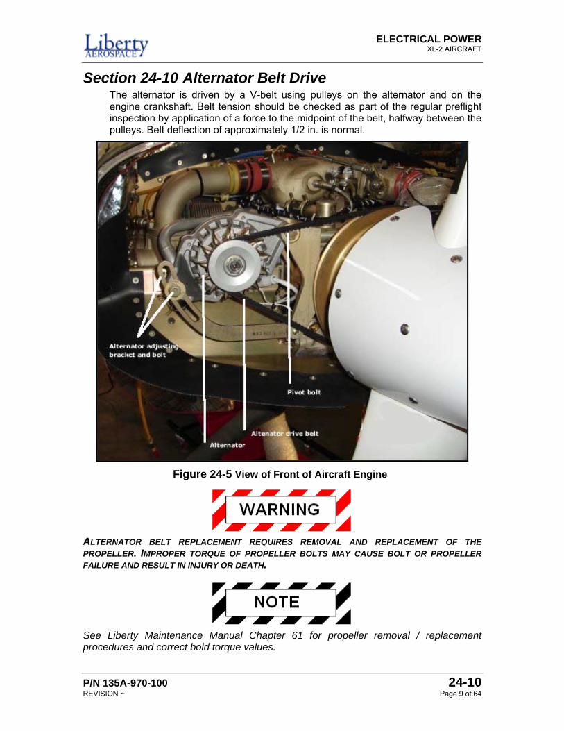
Section 24-10 Alternator Belt Drive The alternator is driven by a V-belt using pulleys on the alternator and on the engine crankshaft. Belt tension should be checked as part of the regular preflight inspection by application of a force to the midpoint of the belt, halfway between the pulleys. Belt deflection of approximately 1/2 in. is normal.
ALTERNATOR BELT REPLACEMENT REQUIRES REMOVAL AND REPLACEMENT OF THE PROPELLER. IMPROPER TORQUE OF PROPELLER BOLTS MAY CAUSE BOLT OR PROPELLER FAILURE AND RESULT IN INJURY OR DEATH.
See Liberty Maintenance Manual Chapter 61 for propeller removal / replacement procedures and correct bold torque values.
Figure 24-5 View of Front of Aircraft Engine
ELECTRICAL POWER XL-2 AIRPLANE
24-10 P/N 135A-970-100 Page 10 of 64 REVISION ~
Section 10-01 Periodic Maintenance Alternator belt inspections take place at 100 hour and annual intervals. Perform the procedure Alternator Belt Operation Check and Inspection on page 14 of this chapter.
Section 10-02 Alternator Belt Procedures This section details the procedures to remove, install, and inspect and check the alternator belt.
ELECTRICAL POWER XL-2 AIRCRAFT
P/N 135A-970-100 24-10 REVISION ~ Page 11 of 64
ALTERNATOR BELT REMOVAL Perform the following procedure to remove the alternator belt.
1. Position the ALT and BAT master switches, the FADEC PWR A and B switches, and the ignition switch to OFF.
2. Remove upper and lower engine cowling.
3. Remove spinner and propeller in accordance with Liberty maintenance manual Chapter 61 procedures.
4. Loosen nuts on alternator mounting bracket and alternator belt tension adjustment bolts. See Figure 24-5 for the location of the alternator tensioning bolts.
5. Move (rotate) alternator toward engine until belt can be lifted off alternator pulley.
6. Lift belt from engine crankshaft pulley and remove belt.
This completes the Alternator Belt Removal procedure.
ELECTRICAL POWER XL-2 AIRPLANE
24-10 P/N 135A-970-100 Page 12 of 64 REVISION ~
ALTERNATOR BELT INSTALLATION Perform the following procedure to install the alternator belt.
1. Position the ALT and BAT master switches, the FADEC PWR A and B switches, and the ignition switch to OFF.
2. Move (rotate) alternator as far as possible toward engine case.
3. Place replacement belt around engine crankshaft and alternator pulleys.
4. Secure alternator attachment and belt tension adjustment nuts; but do not tighten fully.
5. Replace propeller and spinner using Maintenance Manual Chapter 61 procedures
6. Tension the alternator belt in accordance with Alternator Belt Tensioning procedure on page 13 of this chapter.
7. Verify alternator and engine pulley alignment.
8. Replace upper and lower cowlings.
9. Perform the procedure Alternator Belt Operation Check and Inspection on page 14 of this chapter.
This completes the Alternator Belt Installation procedure.
ELECTRICAL POWER XL-2 AIRCRAFT
P/N 135A-970-100 24-10 REVISION ~ Page 13 of 64
ALTERNATOR BELT TENSIONING Perform this procedure to tension the alternator belt to the proper tension.
1. Position the ALT and BAT master switches, the FADEC PWR A and B switches, and the ignition switch to OFF.
2. Remove upper cowling.
3. Loosen pivot sufficiently to permit the alternator to move as the adjustment arm is moved.
4. Loosen the adjustment arm sufficiently to permit alternator rotation along adjustment arm slot.
5. Tension belt to 40 to 45 lbs (½-inch mid-span deflection) and tighten adjustment arm bolt with a torque of 240 to 260 in-lbs. Safety wire bolt head.
6. Tighten pivot bolt with a torque of 400 to 450 in-lbs.
7. Replace upper cowling
8. Run engine over a range of 850 to 2000 RPM for a period of 20 minutes.
9. Return engine to idle (850 to 950 RPM) and shut down.
10. Verify belt tension is 40 to 45 pounds (½-inch mid-span deflection). Adjust as required by repeating steps 1 through step 10.
11. Perform the procedure Alternator Belt Operation Check and Inspection on page 14 of this chapter.
This completes the Alternator Belt Tensioning procedure.
ELECTRICAL POWER XL-2 AIRPLANE
24-10 P/N 135A-970-100 Page 14 of 64 REVISION ~
ALTERNATOR BELT OPERATION CHECK AND INSPECTION Perform this procedure to do an operational check and inspection of the alternator belt.
Refer to the Alternator Belt Troubleshooting Guide for corrective actions as required.
1. Inspect alternator pulley, belt and engine pulley for wear or damage. Do not proceed if damage is present.
2. Verify alternator belt tension is 40 to 45 lbs. (½-inch mid-span deflection).
3. Position the aircraft in the run up area.
4. Perform a standard start and warm up procedure.
5. Set engine to 1700 RPM.
6. Cycle engine throttle from 1000 to 2000 RPM and verify:
a. Main bus voltage remains within the 14.1 to 14.3 Vdc range of operation
b. Main bus amp meter reads above zero
7. ALT FAIL lamp remains OFF.
8. With the engine set for 1700 RPM, position the split Master Switch ALT side to OFF.
9. Verify the ALT FAIL lamp is ON.
10. Position the split Master Switch ALT side to ON.
11. Verify ALT FAIL lamp is OFF.
12. Reduce engine RPM to idle (850 to 950 RPM) and perform an engine shutdown.
13. Verify there is no indication of slippage or damage to the belt, alternator pulley, or engine pulley.
This completes Alternator Belt Operation Check and Inspection.
ELECTRICAL POWER XL-2 AIRCRAFT
P/N 135A-970-100 24-10 REVISION ~ Page 15 of 64
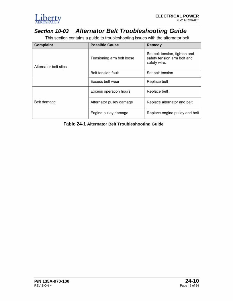
Section 10-03 Alternator Belt Troubleshooting Guide This section contains a guide to troubleshooting issues with the alternator belt.
Complaint Possible Cause Remedy
Tensioning arm bolt loose Set belt tension, tighten and safety tension arm bolt and safety wire.
Belt tension fault Set belt tension Alternator belt slips
Excess belt wear Replace belt
Excess operation hours Replace belt
Alternator pulley damage Replace alternator and belt Belt damage
Engine pulley damage Replace engine pulley and belt
Table 24-1 Alternator Belt Troubleshooting Guide
ELECTRICAL POWER XL-2 AIRPLANE
24-10 P/N 135A-970-100 Page 16 of 64 REVISION ~
PAGE LEFT INTENTIONALLY BLANK
ELECTRICAL POWER XL-2 AIRCRAFT
P/N 135A-970-100 24-30 REVISION E Page 17 of 64
Section 24-30 DC Generation This section details the generation of DC voltage from the airplane’s engine.
Section 30-01 Alternator The alternator (nominal capacity 60 amps maximum at 14.2 Vdc maximum) is mounted on the right side of the front of the engine. Maintenance operations are normally limited to removal and installation of the alternator for condition. For further alternator service information, refer to applicable portions of Teledyne Continental Motors IOF-240-B Overhaul Manual, Teledyne Continental Motors no. OH-22.
Section 30-02 Periodic Maintenance Alternator inspections take place at 100 hour and annual intervals. Perform the procedure Alternator Operation Check and Inspection on page 22 of this chapter.
Section 30-03 Alternator Procedures This section details the procedures to remove, install, and inspect and check the alternator.
ELECTRICAL POWER XL-2 AIRPLANE
24-30 P/N 135A-970-100 Page 18 of 64 REVISION E
ALTERNATOR REMOVAL Perform this procedure to remove the alternator from the airplane.
1. Pull the BAT 1 (CB001) circuit breaker to OPEN.
2. Pull the ALT Field (CB002) circuit breaker to OPEN.
3. Position the ALT and BAT master switches, the FADEC PWR A and B switches, and the ignition switch to OFF.
4. Remove upper and lower engine cowling, in accordance with Chapter 71 – Power Plant.
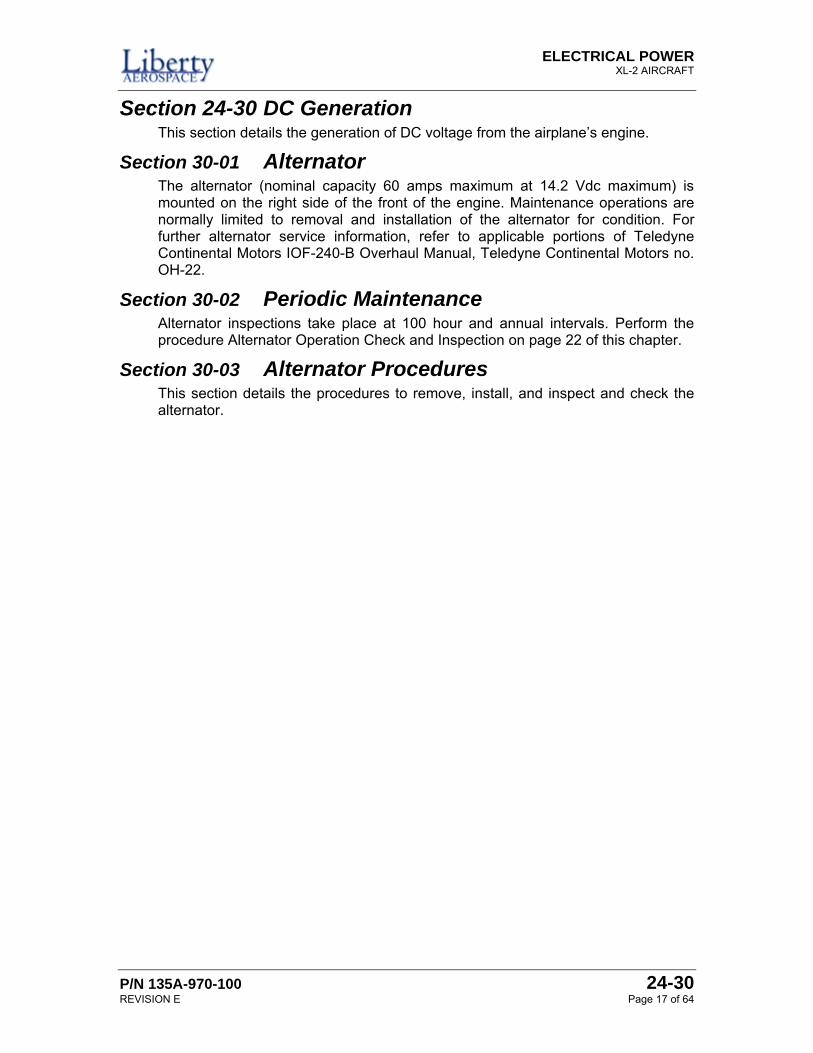
5. Disconnect wire ID: P10B6 and EMI Filter Lead from the “B+” alternator terminal.
6. Disconnect wire ID: P15D16 from “Field” alternator terminal.
7. Disconnect wire ID: P26E16 from “AUX” alternator terminal.
8. Disconnect wire ID: P28A14N from “Ground” alternator terminal
9. Relieve alternator belt tension by removing alternator tension bar bolt.
10. Remove alternator pivot bolt and remove alternator from mounting bracket.
This completes the Alternator Removal procedure.
Figure 24-6 View of Alternator Connections
ELECTRICAL POWER XL-2 AIRCRAFT
P/N 135A-970-100 24-30 REVISION E Page 19 of 64
ALTERNATOR INSTALLATION Perform this procedure to install the alternator on to the airplane.
1. Pull the BAT 1 (CB001) circuit breaker to OPEN.
2. Pull the ALT Field (CB002) circuit breaker to OPEN.
3. Position the ALT and BAT master switches, the FADEC PWR A and B switches, and the ignition switch to OFF.
4. Install alternator using nut and bolt hardware removed previously. The hardware is to remain finger tight only at this time.
5. Perform the Alternator Belt Tensioning on page 11.
6. Connect wire ID: P10B6 and EMI Filter Lead to “B+” terminal on alternator.
7. Connect wire ID: P15D16 to “Field” terminal on alternator,
8. Connect wire ID: P26E16 to “AUX” terminal on alternator
9. Connect wire ID: P28A14N to Ground terminal on alternator
10. Replace upper and lower cowlings.
11. Push in the ALT Field (CB002) circuit breaker to CLOSE.
12. Push in the BAT1 (CB001) circuit breaker to CLOSE.
13. Perform Alternator Operation Check and Inspection on page 22 of this chapter.
This completes the Alternator Installation procedure.
ELECTRICAL POWER XL-2 AIRPLANE
24-30 P/N 135A-970-100 Page 20 of 64 REVISION E
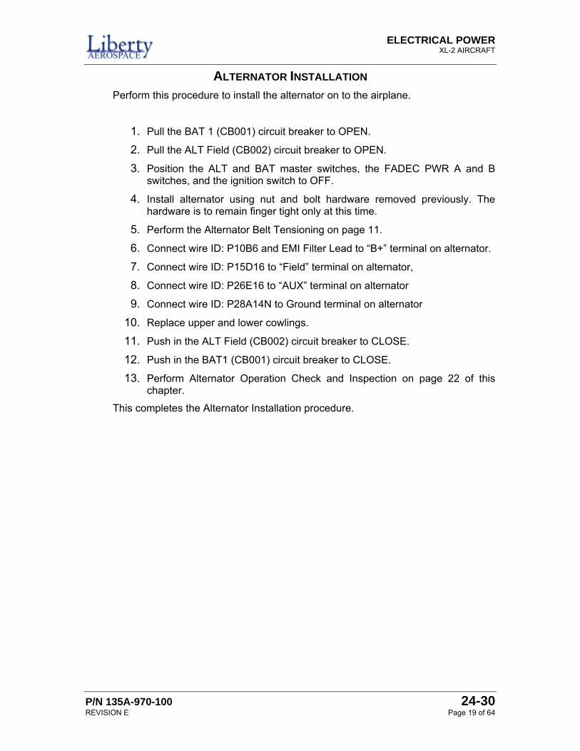
ALTERNATOR FUSE F3 REPLACEMENT Perform this procedure to remove the alternator from the airplane.
1. Pull the BAT 1 (CB001) circuit breaker to OPEN.
2. Pull the ALT Field (CB002) circuit breaker to OPEN.
3. Position the ALT and BAT master switches, the FADEC PWR A and B switches, and the ignition switch to OFF.
4. Remove upper and lower engine cowling, in accordance with Chapter 71 – Power Plant.
Inspect the fuse holder in accordance with SSI-10-001 Alternator Fuse Holder F3 Installation. If the fuse holder installation was correct, continue with this procedure. If the fuse holder installation was incorrect, perform the procedures of SSI-10-001.
5. Holding on to the free end of the fuse, push in on the fuse holder and twist in a counter-clockwise direction.
6. Pull the fuse holder apart.
Figure 24-7 Fuse Holder F3 Disassembly
ELECTRICAL POWER XL-2 AIRCRAFT
P/N 135A-970-100 24-30 REVISION E Page 21 of 64
There is a small rubber “O” ring gasket inside the fuse holder. This gasket should remain in side the large portion of the fuse holder, this is normal. If gasket come out or comes out on the smaller portion of the fuse, insert the gasket back in to the larger portion of the fuse holder.
7. Replace the fuse inside. The fuse is a 5.0 AMP ceramic shell fuse (ABC-5).
8. Insert the small section of the fuse into the larger section and twist in a clockwise direction until the two lock together.
9. Install the lower and upper cowlings, in accordance with Chapter 71 – Power Plant.
10. Close the alternator field circuit breaker ALT Field (CB002).
11. Close the battery circuit breaker BAT 1 (CB001).
This completes the Alternator Fuse F3 Replacement procedure.
ELECTRICAL POWER XL-2 AIRPLANE
24-30 P/N 135A-970-100 Page 22 of 64 REVISION E
ALTERNATOR OPERATION CHECK AND INSPECTION Perform this procedure to do an operational check and inspection of the alternator.
Refer to the Alternator Troubleshooting Guide for corrective actions as required.
1. Position the ALT and BAT master switches, the FADEC PWR A and B switches, and the ignition switch to OFF
2. Remove upper cowling.
3. Inspect and verify alternator terminal connections are secure and free from damage or corrosion.
4. Inspect alternator belt and pulley systems for damage in accordance with Alternator Belt Operation Check and Inspection on page 14 of this chapter.
5. Install upper cowl.
6. Position the airplane in the run up area.
7. Perform a standard start and warm up procedure.
8. Set engine to 1700 RPM.
9. Cycle engine throttle from 1000 to 2000 RPM and verify:
• Main bus voltage remains within the 14.0 to 14.2 Vdc range of operation
• Main bus amp meter reads above zero • ALT FAIL lamp remains OFF
10. With the engine set for 1700 RPM, place the split Master Switch ALT side to OFF.
11. Verify the ALT FAIL lamp is ON.
12. Place the split Master Switch ALT side ON.
13. Verify ALT FAIL lamp is OFF.
14. Return the engine to idle (850 to 950 RPM) and shut down.
This completes the Alternator Operation Check and Inspection.
ELECTRICAL POWER XL-2 AIRCRAFT
P/N 135A-970-100 24-30 REVISION E Page 23 of 64
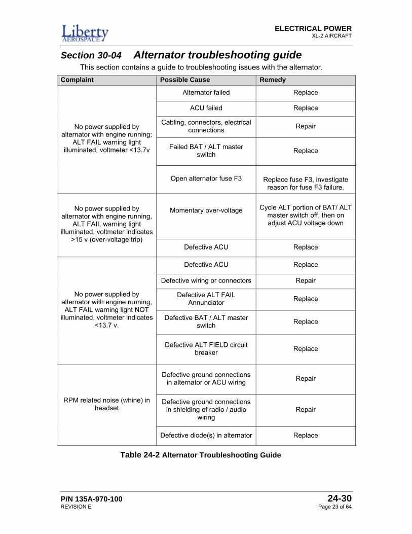
Section 30-04 Alternator troubleshooting guide This section contains a guide to troubleshooting issues with the alternator.
Complaint Possible Cause Remedy
Alternator failed Replace
ACU failed Replace
Cabling, connectors, electrical connections Repair
Failed BAT / ALT master switch Replace
No power supplied by alternator with engine running;
ALT FAIL warning light illuminated, voltmeter <13.7v
Open alternator fuse F3
Replace fuse F3, investigate reason for fuse F3 failure.
Momentary over-voltage
Cycle ALT portion of BAT/ ALT master switch off, then on adjust ACU voltage down
No power supplied by alternator with engine running,
ALT FAIL warning light illuminated, voltmeter indicates
>15 v (over-voltage trip) Defective ACU Replace
Defective ACU Replace
Defective wiring or connectors Repair
Defective ALT FAIL Annunciator Replace
Defective BAT / ALT master switch Replace
No power supplied by alternator with engine running, ALT FAIL warning light NOT
illuminated, voltmeter indicates <13.7 v.
Defective ALT FIELD circuit breaker Replace
Defective ground connections in alternator or ACU wiring
Repair
Defective ground connections in shielding of radio / audio
wiring Repair
RPM related noise (whine) in headset
Defective diode(s) in alternator Replace
Table 24-2 Alternator Troubleshooting Guide
ELECTRICAL POWER XL-2 AIRPLANE
24-30 P/N 135A-970-100 Page 24 of 64 REVISION E
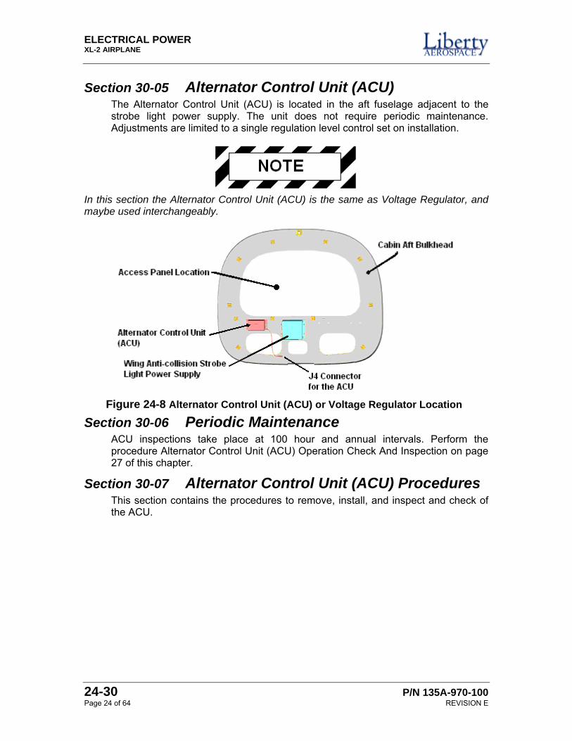
Section 30-05 Alternator Control Unit (ACU) The Alternator Control Unit (ACU) is located in the aft fuselage adjacent to the strobe light power supply. The unit does not require periodic maintenance. Adjustments are limited to a single regulation level control set on installation.
In this section the Alternator Control Unit (ACU) is the same as Voltage Regulator, and maybe used interchangeably.
Section 30-06 Periodic Maintenance ACU inspections take place at 100 hour and annual intervals. Perform the procedure Alternator Control Unit (ACU) Operation Check And Inspection on page 27 of this chapter.
Section 30-07 Alternator Control Unit (ACU) Procedures This section contains the procedures to remove, install, and inspect and check of the ACU.
Figure 24-8 Alternator Control Unit (ACU) or Voltage Regulator Location
ELECTRICAL POWER XL-2 AIRCRAFT
P/N 135A-970-100 24-30 REVISION E Page 25 of 64
ALTERNATOR CONTROL UNIT (ACU) REMOVAL Perform this procedure to remove the alternator control unit.
Before starting this procedure, the tail of the airplane requires support. Failure to support the airplane’s tail may cause damage to the airplane’s tail section while accessing any area aft of the passenger compartment.
1. Position the ALT and BAT master switches, the FADEC PWR A and B switches, and the ignition switch to OFF.
2. Install a tail stand underneath the tail section of the airplane.
3. Remove the cabin aft bulkhead access panel, by removing securing screw hardware.
4. Disconnect connector J4 from ACU.
5. Remove ACU bracket 10-32 mounting bolts and lift the ACU out of the fuselage.
This completes the Alternator Control Unit (ACU) Removal procedure.
ELECTRICAL POWER XL-2 AIRPLANE
24-30 P/N 135A-970-100 Page 26 of 64 REVISION E
ALTERNATOR CONTROL UNIT (ACU) INSTALLATION Perform this procedure to install the alternator control unit.
Before starting this procedure, the tail of the airplane requires support. Failure to support the airplane’s tail may cause damage to the airplane’s tail section while accessing any area aft of the passenger compartment.
1. Position the ALT and BAT master switches, the FADEC PWR A and B switches, and the ignition switch to OFF.
2. Install a tail stand underneath the tail section of the airplane.
3. Remove the cabin aft bulkhead access panel, by removing securing screw hardware.
4. Position the ACU on the aft fuselage bulkhead adjacent to the strobe light power supply and secure with 10-32 bolts hardware removed previously.
5. Connect J4 turn locking ring until detent is felt to be engaged.
6. Perform the Alternator Control Unit (ACU) Operation Check And Inspection on page 27.
7. Install the cabin aft bulkhead access panel.
8. Remove the tail support.
This completes the Alternator Control Unit (ACU) Installation procedure.
ELECTRICAL POWER XL-2 AIRCRAFT
P/N 135A-970-100 24-30 REVISION E Page 27 of 64
ALTERNATOR CONTROL UNIT (ACU) OPERATION CHECK AND INSPECTION Perform this procedure to do an operational check and inspection of the alternator control unit.
Refer to the ACU Troubleshooting Guide for corrective actions as required.
1. Install a tail stand
2. Remove the cabin aft bulkhead access panel by removal of retaining screws.
3. Inspect the ACU installation for the following:
• Secure mounting • Proper electrical connection • Corrosion or physical damage • Correct deficiencies found by repair or replacement of the ACU.
4. Remove the tail stand
5. Position aircraft in the run up area
6. Set the aircraft parking brake
7. Perform a standard start and warm up procedure
8. Set engine to 1700 RPM
9. Verify flight instrument panel mounted “Alt Fail” annunciator is NOT on. If the annunciator is on refer to troubleshooting guide for next action.
10. Verify the ACU mounted status annunciator is NOT on. If the annunciator is on refer to troubleshooting guide for next action.
11. Note the VM1000FX voltage reading. If the reading is 14.1 ± 0.1 Vdc proceed with step 19.
12. Return the engine to idle (850 to 950 RPM) and shut down.
13. Install a tail stand
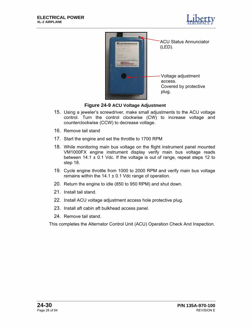
14. Access the ACU adjustment by removing the access hole protective plug, as shown in Figure 24-9.
ELECTRICAL POWER XL-2 AIRPLANE
24-30 P/N 135A-970-100 Page 28 of 64 REVISION E
15. Using a jeweler’s screwdriver, make small adjustments to the ACU voltage control. Turn the control clockwise (CW) to increase voltage and counterclockwise (CCW) to decrease voltage.
16. Remove tail stand
17. Start the engine and set the throttle to 1700 RPM
18. While monitoring main bus voltage on the flight instrument panel mounted VM1000FX engine instrument display verify main bus voltage reads between 14.1 ± 0.1 Vdc. If the voltage is out of range, repeat steps 12 to step 18.
19. Cycle engine throttle from 1000 to 2000 RPM and verify main bus voltage remains within the 14.1 ± 0.1 Vdc range of operation.
20. Return the engine to idle (850 to 950 RPM) and shut down.
21. Install tail stand.
22. Install ACU voltage adjustment access hole protective plug.
23. Install aft cabin aft bulkhead access panel.
24. Remove tail stand.
This completes the Alternator Control Unit (ACU) Operation Check And Inspection.
Figure 24-9 ACU Voltage Adjustment
Voltage adjustment access. Covered by protective plug.
ACU Status Annunciator (LED).
ELECTRICAL POWER XL-2 AIRCRAFT
P/N 135A-970-100 24-30 REVISION E Page 29 of 64
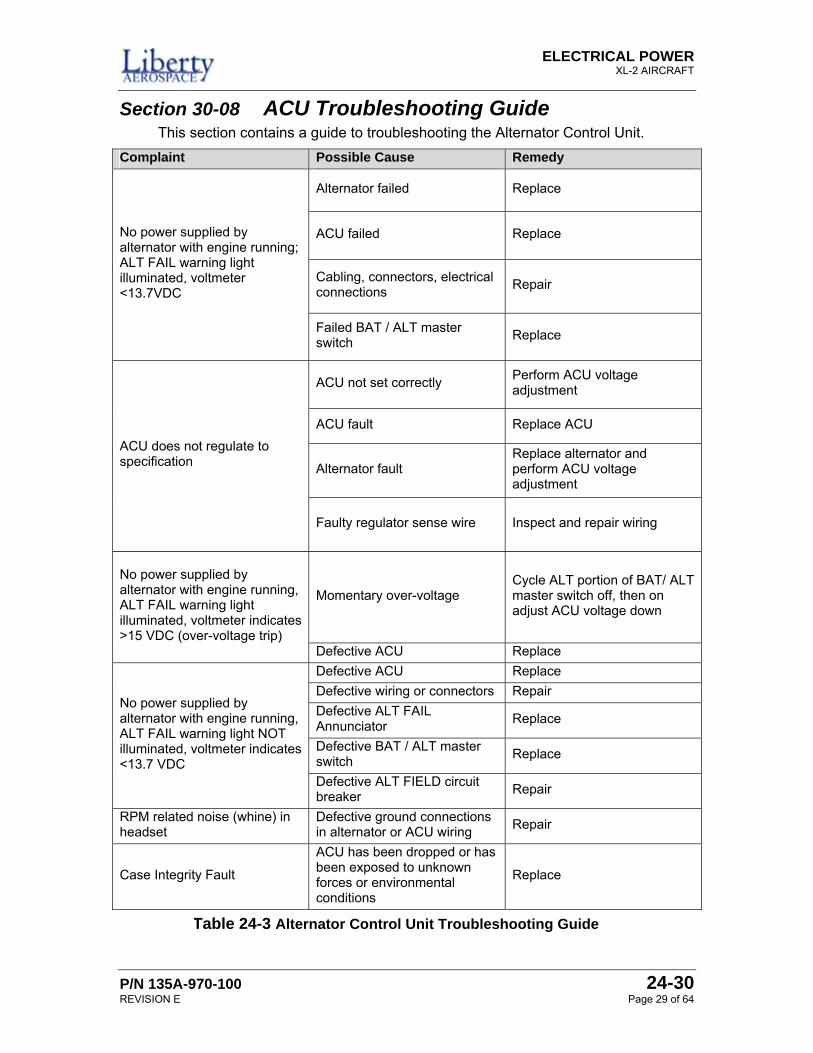
Section 30-08 ACU Troubleshooting Guide This section contains a guide to troubleshooting the Alternator Control Unit.
Complaint Possible Cause Remedy
Alternator failed Replace
ACU failed Replace
Cabling, connectors, electrical connections Repair
No power supplied by alternator with engine running; ALT FAIL warning light illuminated, voltmeter <13.7VDC
Failed BAT / ALT master switch Replace
ACU not set correctly Perform ACU voltage adjustment
ACU fault Replace ACU
Alternator fault Replace alternator and perform ACU voltage adjustment
ACU does not regulate to specification
Faulty regulator sense wire Inspect and repair wiring
Momentary over-voltage Cycle ALT portion of BAT/ ALT master switch off, then on adjust ACU voltage down
No power supplied by alternator with engine running, ALT FAIL warning light illuminated, voltmeter indicates >15 VDC (over-voltage trip)
Defective ACU Replace Defective ACU Replace Defective wiring or connectors Repair Defective ALT FAIL Annunciator Replace
Defective BAT / ALT master switch Replace
No power supplied by alternator with engine running, ALT FAIL warning light NOT illuminated, voltmeter indicates <13.7 VDC
Defective ALT FIELD circuit breaker Repair
RPM related noise (whine) in headset
Defective ground connections in alternator or ACU wiring Repair
Case Integrity Fault
ACU has been dropped or has been exposed to unknown forces or environmental conditions
Replace
Table 24-3 Alternator Control Unit Troubleshooting Guide
ELECTRICAL POWER XL-2 AIRPLANE
24-30 P/N 135A-970-100 Page 30 of 64 REVISION E
Section 30-09 Batteries This section details information about the battery systems for the airplane.
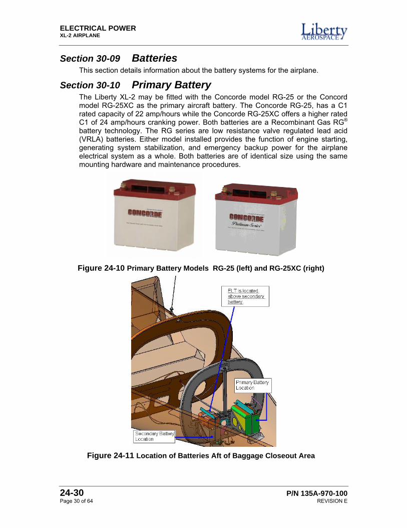
Section 30-10 Primary Battery The Liberty XL-2 may be fitted with the Concorde model RG-25 or the Concord model RG-25XC as the primary aircraft battery. The Concorde RG-25, has a C1 rated capacity of 22 amp/hours while the Concorde RG-25XC offers a higher rated C1 of 24 amp/hours cranking power. Both batteries are a Recombinant Gas RG® battery technology. The RG series are low resistance valve regulated lead acid (VRLA) batteries. Either model installed provides the function of engine starting, generating system stabilization, and emergency backup power for the airplane electrical system as a whole. Both batteries are of identical size using the same mounting hardware and maintenance procedures.
Figure 24-10 Primary Battery Models RG-25 (left) and RG-25XC (right)
Figure 24-11 Location of Batteries Aft of Baggage Closeout Area
ELECTRICAL POWER XL-2 AIRCRAFT
P/N 135A-970-100 24-30 REVISION E Page 31 of 64
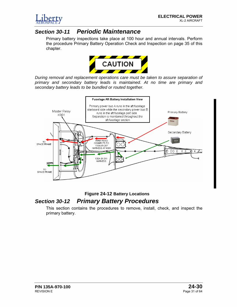
Section 30-11 Periodic Maintenance Primary battery inspections take place at 100 hour and annual intervals. Perform the procedure Primary Battery Operation Check and Inspection on page 35 of this chapter.
During removal and replacement operations care must be taken to assure separation of primary and secondary battery leads is maintained. At no time are primary and secondary battery leads to be bundled or routed together.
Section 30-12 Primary Battery Procedures This section contains the procedures to remove, install, check, and inspect the primary battery.
Figure 24-12 Battery Locations
ELECTRICAL POWER XL-2 AIRPLANE
24-30 P/N 135A-970-100 Page 32 of 64 REVISION E
PRIMARY BATTERY REMOVAL Perform this procedure to remove the primary battery from the airplane.
Before starting this procedure, the tail of the airplane requires support. Failure to support the airplane’s tail may cause damage to the airplane’s tail section while accessing any area aft of the passenger compartment.
1. Position the ALT and BAT master switches, the FADEC PWR A and B switches, and the ignition switch to OFF.
2. Pull the BAT1 (CB001) circuit breaker to OPEN.
3. Install a tail stand underneath the tail section of the airplane.
4. Remove the cabin aft bulkhead access panel, by removing securing screw hardware.
5. Disconnect the negative then the positive leads from the primary battery. Isolate the negative terminals on the batteries to prevent accidental connection.
6. Remove primary battery hold-down bolts.
The primary battery is very heavy. Obtain assistance while removing the primary battery from the airplane.
7. Remove primary battery
8. If the primary battery is to be installed later, perform Primary Battery Operation Check and Inspection on page 35 of this chapter.
This completes the Primary Battery Removal procedure.
ELECTRICAL POWER XL-2 AIRCRAFT
P/N 135A-970-100 24-30 REVISION E Page 33 of 64
PRIMARY BATTERY INSTALLATION Perform this procedure to install the primary battery into the airplane.
1. Verify that replacement battery is correct type.
2. Perform the procedure Primary Battery Operation Check and Inspection on page 35 of this chapter.
Before starting this procedure, the tail of the airplane requires support. Failure to support the airplane’s tail may cause damage to the airplane’s tail section while accessing any area aft of the passenger compartment.
3. Position the ALT and BAT master switches, the FADEC PWR A and B switches, and the ignition switch to OFF.
4. Pull the BAT1 (CB001) circuit breaker to OPEN.
5. Install a tail stand underneath the tail section of the airplane.
6. Remove the cabin aft bulkhead access panel, by removing securing screw hardware.
7. Clean battery terminals with a stiff brush and contact cleaner.
8. Clean battery cable terminals with stiff brush and contact cleaner
The primary battery is very heavy. Obtain assistance while installing the primary battery to the airplane.
9. Position battery in battery tray with terminals oriented outboard
10. Install and secure battery hold down bar with two AN4 ¼-28 bolts. Safety wire bolts heads.
Always connect negative battery cable last.
11. Install positive battery lead P01A2 with terminal bolt. Apply a torque of 70 in-lbs ± 5 in-lbs.
12. Install negative battery lead P07A2N with terminal bolt, Apply a torque of 70 in-lbs ± 5in-lbs.
ELECTRICAL POWER XL-2 AIRPLANE
24-30 P/N 135A-970-100 Page 34 of 64 REVISION E
13. Apply a thin coating of Dow Corning 4 (DC4) electrical insulating compound over the terminal/bolt assembly.
14. Push in the BAT1 (CB001) to CLOSE.
15. Position the split master switch BAT side to ON
16. Verify OAT voltage meter function indication is within +/- 1 volt of operational check reading performed in step 2 above.
17. Position the split master switch to OFF
18. Install cabin aft bulkhead access panel.
19. Remove the tail support.
This completes the Primary Battery Installation procedure.
ELECTRICAL POWER XL-2 AIRCRAFT
P/N 135A-970-100 24-30 REVISION E Page 35 of 64
PRIMARY BATTERY OPERATION CHECK AND INSPECTION Perform this procedure to do an operational check and inspection of the primary battery.
Refer to the Primary Battery Troubleshooting Guide for corrective actions as required.
1. Perform primary battery removal as described in Primary Battery Removal shown on page 32 of this chapter.
2. Inspect battery terminals for corrosion, damage or signs of fatigue.
3. Inspect battery cable terminals for corrosion, damage or signs of fatigue.
4. Inspect battery case for cracks or other physical damage.
5. Inspect battery tray and hold down hardware for corrosion, structural damage or signs of fatigue. Replace corroded, damaged or fatigued components.
6. Inspect battery for time in service.
a. A primary battery exceeding life limits provided in maintenance manual Chapter 04 must be replaced.
b. A primary battery in service for 24 months or 1200 hours of operation, whichever occurs first, requires an initial capacity test in accordance with Concord Battery procedure 5-0142. The battery is acceptable for use with a capacity of 85% or greater of nominal rated capacity (C1).
c. A primary battery in service for 12 months or 200 hours of operation, whichever occurs first since an initial capacity test and not in excess of Chapter 04 replacement limitations, requires a capacity test in accordance with Concord Battery procedure 5-0142. The battery is acceptable for use with a capacity of 85% or greater of nominal rated capacity (C1).
7. Using a DC voltmeter measure voltage across the battery terminals and note the state of charge per Table 24-4:
State of Charge 12 Volt Open Circuit Voltage
100% 12.9 Vdc 75% 12.7 Vdc 50% 12.4 Vdc 25% 12.0 Vdc 0% ≤ 11.7 Vdc
Table 24-4 Table showing the Open Circuit Voltage indicating state of charge
ELECTRICAL POWER XL-2 AIRPLANE
24-30 P/N 135A-970-100 Page 36 of 64 REVISION E
8. Charge the battery using a constant potential capable charger at 14.1 volts until the charge current stabilizes for 1 hour
9. Verify the battery did not become very hot, 55°C (130°F) or greater, during the charge process. Replace battery is temperature exceeds limit.
10. Measure and note the voltage across the battery terminals, using a DC voltmeter, and note the state of charge per Table 24-4 above. If the battery has not achieved a 100% threshold of 12.9 Vdc state of charge, perform battery capacity test in accordance with Concord Battery maintenance manual 5-0142. A battery that fails to achieve 80% capacity must be replaced.
11. Perform the procedure Primary Battery Installation shown on page 33 of this chapter.
12. Operation check and inspection complete.
This completes the Primary Battery Operation Check and Inspection procedure.
ELECTRICAL POWER XL-2 AIRCRAFT
P/N 135A-970-100 24-30 REVISION E Page 37 of 64
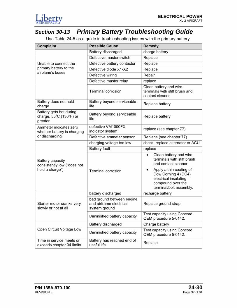
Section 30-13 Primary Battery Troubleshooting Guide Use Table 24-5 as a guide in troubleshooting issues with the primary battery.
Complaint Possible Cause Remedy Battery discharged charge battery Defective master switch Replace Defective battery contactor Replace Defective diode X1-X2 Replace Defective wiring Repair Defective master relay replace
Unable to connect the primary battery to the airplane’s buses
Terminal corrosion Clean battery and wire terminals with stiff brush and contact cleaner
Battery does not hold charge
Battery beyond serviceable life Replace battery
Battery gets hot during charge, 550C (1300F) or greater
Battery beyond serviceable life Replace battery
defective VM1000FX indicator system replace (see chapter 77) Ammeter indicates zero
whether battery is charging or discharging Defective ammeter sensor Replace (see chapter 77)
charging voltage too low check, replace alternator or ACU Battery fault replace
Battery capacity consistently low (“does not hold a charge”) Terminal corrosion
• Clean battery and wire terminals with stiff brush and contact cleaner
• Apply a thin coating of Dow Corning 4 (DC4) electrical insulating compound over the terminal/bolt assembly.
battery discharged recharge battery bad ground between engine and airframe electrical system ground
Replace ground strap Starter motor cranks very slowly or not at all
Diminished battery capacity Test capacity using Concord OEM procedure 5-0142.
Battery discharged Charge battery Open Circuit Voltage Low
Diminished battery capacity Test capacity using Concord OEM procedure 5-0142.
Time in service meets or exceeds chapter 04 limits
Battery has reached end of useful life Replace
ELECTRICAL POWER XL-2 AIRPLANE
24-30 P/N 135A-970-100 Page 38 of 64 REVISION E
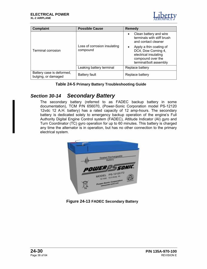
Complaint Possible Cause Remedy
Loss of corrosion insulating compound
• Clean battery and wire terminals with stiff brush and contact cleaner
• Apply a thin coating of DC4, Dow Corning 4, electrical insulating compound over the terminal/bolt assembly
Terminal corrosion
Leaking battery terminal Replace battery Battery case is deformed, bulging, or damaged Battery fault Replace battery
Section 30-14 Secondary Battery The secondary battery (referred to as FADEC backup battery in some documentation), TCM P/N 656070, (Power-Sonic Corporation model PS-12120 12vdc 12 A.H. battery) has a rated capacity of 12 amp-hours. The secondary battery is dedicated solely to emergency backup operation of the engine’s Full Authority Digital Engine Control system (FADEC), Attitude Indicator (AI) gyro and Turn Coordinator (TC) gyro operation for up to 60 minutes. This battery is charged any time the alternator is in operation, but has no other connection to the primary electrical system.
Table 24-5 Primary Battery Troubleshooting Guide
Figure 24-13 FADEC Secondary Battery
ELECTRICAL POWER XL-2 AIRCRAFT
P/N 135A-970-100 24-30 REVISION E Page 39 of 64
Section 30-15 Periodic Maintenance Secondary battery inspections take place at annual intervals. Perform inspection in accordance with Secondary Battery Operational Check and Inspection on page 42 of this chapter.
The secondary battery, providing backup power for the engine FADEC system, must be replaced at specific service intervals regardless of condition. See Liberty Maintenance Manual Chapter 04 limitations.
During removal and replacement operations care must be taken to assure separation of primary and secondary battery leads is maintained. At no time are primary and secondary battery leads to be bundled or routed together.
Section 30-16 Secondary Battery Procedures This section contains the procedures to remove, install, and check and inspect the secondary battery.
ELECTRICAL POWER XL-2 AIRPLANE
24-30 P/N 135A-970-100 Page 40 of 64 REVISION E
SECONDARY BATTERY REMOVAL Perform the following procedure to remove the secondary battery from the airplane.
Before starting this procedure, the tail of the airplane requires support. Failure to support the airplane’s tail may cause damage to the airplane’s tail section while accessing any area aft of the passenger compartment.
1. Position the ALT and BAT master switches, the FADEC PWR A and B switches, and the ignition switch to OFF.
2. Pull the SPSC (CB024) circuit breaker to OPEN.
3. Install a tail stand underneath the tail section of the airplane.
4. Remove the cabin aft bulkhead access panel, by removing securing screw hardware.
Take care when removing the ELT from its mounting above the secondary battery. Failure to properly remove the ELT can trigger a false emergency signal. Possible fines may be imposed if there is a false activation of an ELT.
5. Remove Emergency Locator Transmitter by Maintenance Manual Chapter 25 procedure.
6. Disconnect the negative then the positive leads from the secondary battery. Isolate the negative terminal on the batteries to prevent accidental connection.
7. Remove battery hold-down bracket bolts and remove bracket.
8. Remove battery.
This completes the Secondary Battery Removal procedure.
ELECTRICAL POWER XL-2 AIRCRAFT
P/N 135A-970-100 24-30 REVISION E Page 41 of 64
SECONDARY BATTERY INSTALLATION Perform this procedure to install the secondary battery.
1. Verify that replacement battery is correct type and that it is properly charged.
Before starting this procedure, the tail of the airplane requires support. Failure to support the airplane’s tail may cause damage to the airplane’s tail section while accessing any area aft of the passenger compartment.
2. Position the ALT and BAT master switches, the FADEC PWR A and B switches, and the ignition switch to OFF. Pull the SPSC (CB024) circuit breaker to OPEN.
3. Install a tail stand underneath the tail section of the airplane. Remove the cabin aft bulkhead access panel, by removing securing screw hardware.
4. Position battery in battery tray with terminals oriented aft.
5. Connect secondary battery cable positive and negative quick disconnects.
6. Apply a thin coating of Dow Corning 4 electrical insulating compound, DC4, over the terminal/bolt assembly.
7. Install battery hold down bracket with two bolts. Safety wire bolt heads.
Take care when installing the ELT to its mounting position. Failure to properly install the ELT can trigger a false emergency signal. Possible fines may be imposed if there is a false activation of an ELT.
8. Install Emergency Locator Transmitter in accordance with Chapter 25 – Equipment and Furnishings.
9. Push in the SPSC (CB024) circuit breaker to CLOSE.
10. Position the FADEC PWR B switch ON.
11. Verify the FADEC HSA is illuminated.
12. Verify Attitude Indicator (AI) and Turn Coordinator (TC) gyros are spinning.
13. Position the FADEC PWR B switch OFF.
14. Install baggage compartment closeout panel.
15. Remove the tail support.
This completes the Secondary Battery Installation procedure.
ELECTRICAL POWER XL-2 AIRPLANE
24-30 P/N 135A-970-100 Page 42 of 64 REVISION E
SECONDARY BATTERY OPERATIONAL CHECK AND INSPECTION Perform the following procedure to do an operational check and inspection of the secondary battery.
Refer to the Secondary Battery Troubleshooting Guide for corrective actions as required.
1. Remove the secondary battery from the airplane per the procedure Secondary Battery Removal as shown on page 40 of this chapter.
2. Inspect battery terminals for corrosion, damage or signs of fatigue. Inspect battery cable terminals for corrosion, damage or signs of fatigue. Inspect battery case for cracks or other physical damage.
3. Inspect battery tray and hold down hardware for corrosion, structural damage or signs of fatigue. Inspect battery for time in service. A secondary battery exceeding life limits provided in maintenance manual Chapter 04 must be replaced.
4. Using a DC voltmeter measure voltage across the battery terminals and note the state of charge per the chart below:
State of Charge 12 Volt Open Circuit Voltage
100% 12.9 Vdc 75% 12.7 Vdc 50% 12.4 Vdc 25% 12.0 Vdc 0% ≤ 11.7 Vdc
5. Using a Constant Potential (CP) charger set to 14.1 volts, charge the battery until battery current drawn reaches 0.120 amps. Discontinue charging once this current has been reached.
6. Verify the battery case temperature did not reach, 55°C (130°F) or greater, during the charge process. Replace battery if temperature exceeds limit.
7. Using a DC voltmeter, measure the open circuit voltage across the battery terminals and note the state of charge per Table 24-6 above. If the battery has not achieved a 100% state of charge threshold of 12.9Vdc, replace the battery.
8. Install the secondary battery per the procedure Primary Battery Installation as shown on page 41 of this chapter.
This completes the Secondary Battery Operational Check and Inspection procedure.
Table 24-6 Table showing the Open Circuit Voltage indicating state of charge
ELECTRICAL POWER XL-2 AIRCRAFT
P/N 135A-970-100 24-30 REVISION E Page 43 of 64
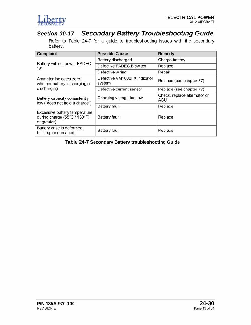
Section 30-17 Secondary Battery Troubleshooting Guide Refer to Table 24-7 for a guide to troubleshooting issues with the secondary battery.
Complaint Possible Cause Remedy Battery discharged Charge battery Defective FADEC B switch Replace Battery will not power FADEC
“B” Defective wiring Repair Defective VM1000FX indicator system Replace (see chapter 77) Ammeter indicates zero
whether battery is charging or discharging Defective current sensor Replace (see chapter 77)
Charging voltage too low Check, replace alternator or ACU Battery capacity consistently
low (“does not hold a charge”) Battery fault Replace
Excessive battery temperature during charge (550C / 1300F) or greater)
Battery fault Replace
Battery case is deformed, bulging, or damaged. Battery fault Replace
Table 24-7 Secondary Battery troubleshooting Guide
ELECTRICAL POWER XL-2 AIRPLANE
24-30 P/N 135A-970-100 Page 44 of 64 REVISION E
PAGE LEFT INTENTIONALLY BLANK
ELECTRICAL POWER XL-2 AIRCRAFT
P/N 135A-970-100 24-60 REVISION D Page 45 of 64
Section 24-60 DC Electrical Load Distribution This section details the DC electrical load distribution for the airplane.
Section 60-01 DC Power Distribution DC power from the primary battery is routed to the main distribution bus through a 70-amp circuit breaker. Power from the alternator is connected directly to the main distribution bus, with control and protection provided by the ACU. Circuit breakers and fuses protect individual circuits powering various airplane subsystems and components from the main distribution bus.
The airplane uses an entirely separate “FADEC power B bus” in emergencies. This bus, powered by the secondary battery, provides backup power for the engine FADEC system, Attitude Indicator (AI) gyro, and Turn Coordinator (TC) gyro operation for up to 60 minutes. In normal operation, this bus maintains the secondary battery in a fully charged condition at all times.
Section 60-02 Periodic Maintenance The DC power distribution system does not require periodic maintenance cycles. In the event that a fault condition is noted perform the procedure Circuit Breaker and Master Relay Operation Check And Inspection on page 53 of this chapter.
Section 60-03 Circuit Breaker and Master Relay Procedures
This section details the removal, installation and inspections of the DC power distribution system. These procedures cover the removal and installation of an individual circuit breaker and the removal and installation of the master relay, K001.
ELECTRICAL POWER XL-2 AIRPLANE
24-60 P/N 135A-970-100 Page 46 of 64 REVISION D
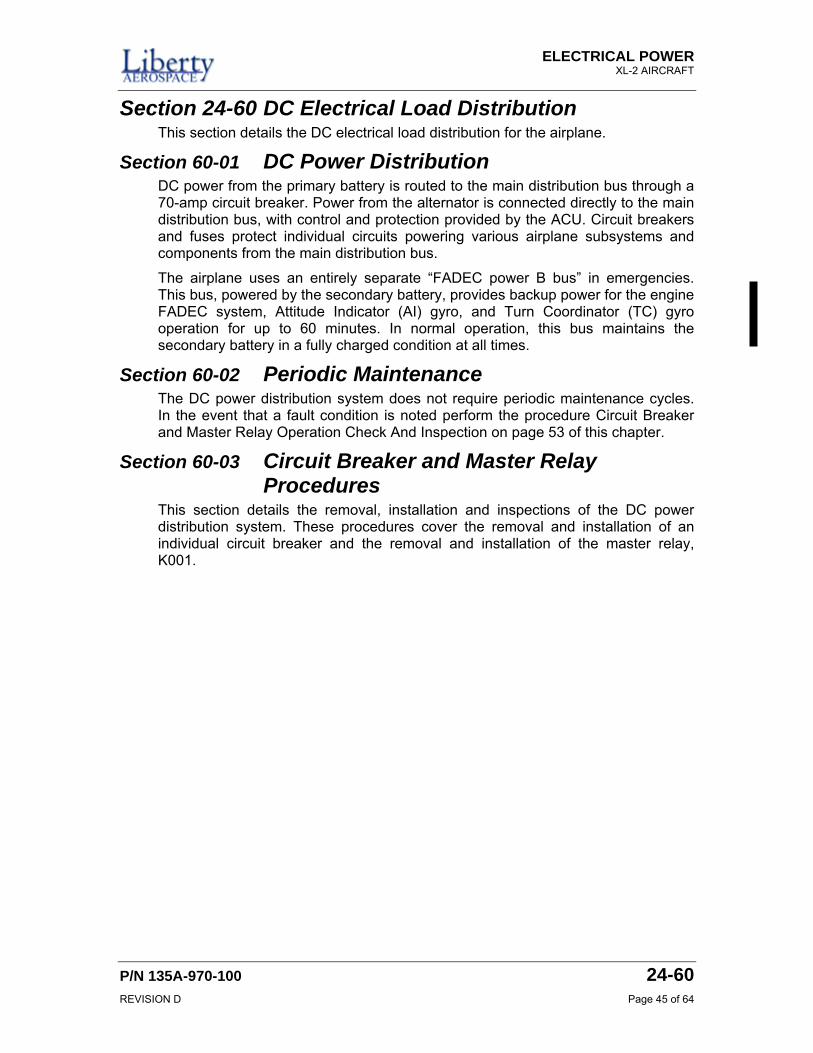
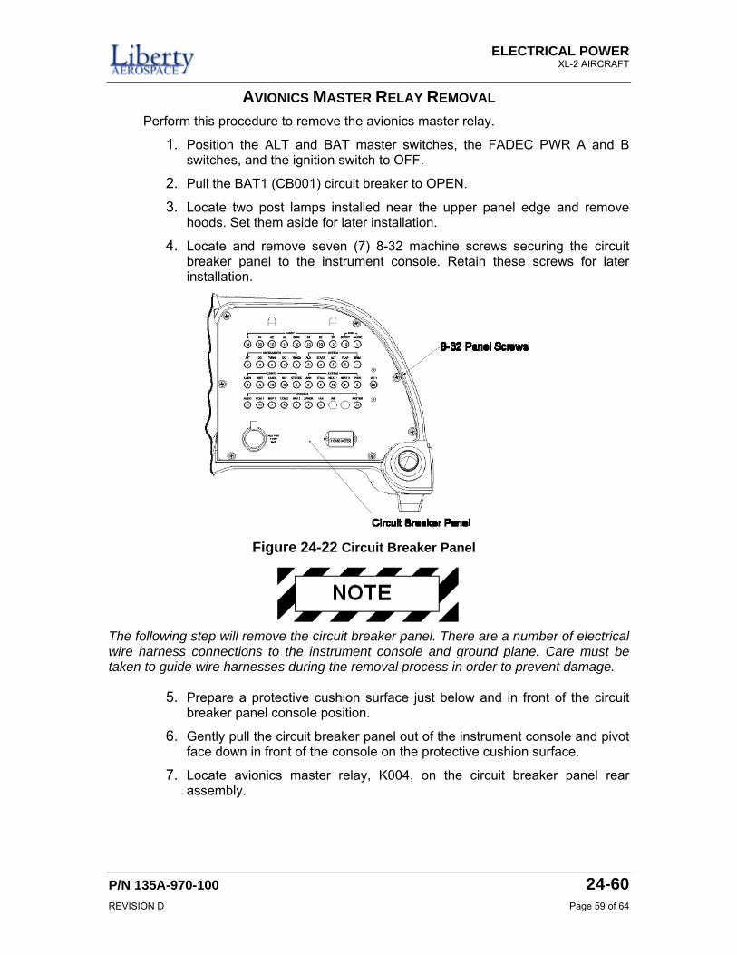
CIRCUIT BREAKER REMOVAL Perform this procedure to remove an individual circuit breaker from the circuit breaker panel.
1. Pull circuit breaker BAT 1 (CB001) to OPEN.
2. Position the ALT and BAT master switches, the FADEC PWR A and B switches, and the ignition switch to OFF.
3. Locate two post lamps installed near the upper panel edge and remove hoods. Set them aside for later installation.
4. Locate and remove seven (7) 8-32 machine screws securing the circuit breaker panel to the instrument console. Retain these screws for later installation.
The following step will remove the circuit breaker panel. There are a number of electrical wire harness connections to the instrument console and ground plane. Care must be taken to guide wire harnesses during the removal process in order to prevent damage.
5. Prepare a protective cushion surface just below and in front of the circuit breaker panel console position.
6. Gently pull the circuit breaker panel out of the instrument console and pivot face down in front of the console on the protective cushion surface.
7. Disconnect engine data processing unit ribbon cable connector PVM03A from DPU connector PVM03
8. Disconnect engine data processing unit cable connector PVM01 from DPU connector PVM01.
Figure 24-14 Circuit Breaker Panel
ELECTRICAL POWER XL-2 AIRCRAFT
P/N 135A-970-100 24-60 REVISION D Page 47 of 64
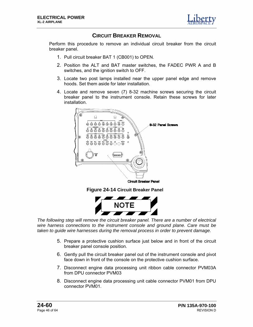
9. Disconnect engine data processing unit cable connector PVM04 from DPU connector PVM04.
10. Remove four (4) 6-32 screws holding the DPU mounting bracket to the circuit breaker panel assembly. See Figure 24-15 for the location of the DPU mounting screws.
11. Remove the DPU and mounting bracket as an assembly. Retain for later installation.
12. Remove the line ring terminal from the circuit breaker. If ganged together with other circuit breakers, remove the bus bar connecting the gang of circuit breakers. Removing the bus bar from the circuit breakers will facilitate the removal of the circuit breaker. Remove load ring terminal and remove circuit breaker from the panel. Retain these screws for later installation.
13. Loosen circuit breaker retention nut and remove circuit breaker from panel assembly.
This completes the Circuit Breaker Removal procedure.
Figure 24-15 DPU Bracket Mounting Screws
Figure 24-16 Circuit Breaker Mounting Hardware
ELECTRICAL POWER XL-2 AIRPLANE
24-60 P/N 135A-970-100 Page 48 of 64 REVISION D
CIRCUIT BREAKER INSTALLATION Perform this procedure to install an individual circuit breaker from the circuit breaker panel.
1. Position replacement circuit breaker in panel location and install retention nut finger tight.
2. Install circuit breaker bus bar screw and tighten to a torque of 9-12 in-lbs. If installing CB001, tighten the terminal bolt to a torque of 50 to 100 in-lbs.
3. Install circuit breaker load wire ring terminal(s) screw and tighten to a torque of 9-12 in/lbs. If installing CB001, tighten the terminal bolt to a torque of 50 to 100 in-lbs.
4. Tighten circuit breaker retention nut.
5. Position the DPU and the DPU mounting bracket assembly. Secure with four (4) 6-32 machine screws.
6. Connect engine data processing unit ribbon cable connector PVM03A to DPU connector PVM03
7. Connect engine data processing unit cable connector PVM01 to DPU connector PVM01.
8. Connect engine data processing unit cable connector PVM04 to DPU connector PVM04.
The following steps install the circuit breaker panel into the instrument console. To avoid damage to the wiring harness, use care during the installation of the circuit breaker panel.
9. Gently pivot circuit breaker panel to vertical and slide into the instrument console.
10. Install seven (7) 8-32 machine screws securing the circuit breaker panel to the instrument console.
11. Install two post lamp hoods removed previously.
12. Push circuit breaker BAT 1 (CB001) to CLOSED
13. Perform operation check and inspection in the procedure Circuit Breaker and Master Relay Operation Check And Inspection on page 53 of this chapter.
This completes the Circuit Breaker Installation procedure.
ELECTRICAL POWER XL-2 AIRCRAFT
P/N 135A-970-100 24-60 REVISION D Page 49 of 64
MASTER RELAY REMOVAL Perform this procedure to remove the master relay.
Before starting this procedure, the tail of the airplane requires support. Failure to support the airplane’s tail may cause damage to the airplane’s tail section while accessing any area aft of the passenger compartment.
1. Position the ALT and BAT master switches, the FADEC PWR A and B switches, and the ignition switch to OFF.
2. Pull the BAT1 (CB001) circuit breaker to OPEN.
3. Install a tail stand underneath the tail section of the airplane.
4. Remove the cabin aft bulkhead access panel, by removing securing screw hardware.
5. Locate and disconnect primary battery terminal cable P07A2N (Negative) from the battery.
6. Locate and disconnect primary battery terminal cable P01A2 (Positive) from the battery.
Failure to disconnect the battery can cause damage to the electrical circuitry of the airplane.
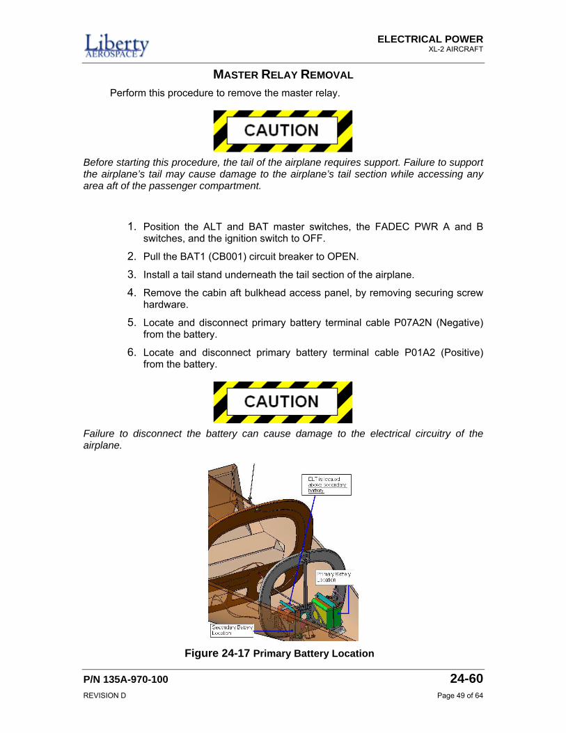
Figure 24-17 Primary Battery Location
ELECTRICAL POWER XL-2 AIRPLANE
24-60 P/N 135A-970-100 Page 50 of 64 REVISION D
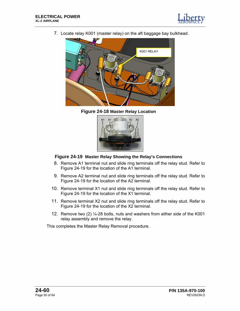
7. Locate relay K001 (master relay) on the aft baggage bay bulkhead.
8. Remove A1 terminal nut and slide ring terminals off the relay stud. Refer to Figure 24-19 for the location of the A1 terminal.
9. Remove A2 terminal nut and slide ring terminals off the relay stud. Refer to Figure 24-19 for the location of the A2 terminal.
10. Remove terminal X1 nut and slide ring terminals off the relay stud. Refer to Figure 24-19 for the location of the X1 terminal.
11. Remove terminal X2 nut and slide ring terminals off the relay stud. Refer to Figure 24-19 for the location of the X2 terminal.
12. Remove two (2) ¼-28 bolts, nuts and washers from either side of the K001 relay assembly and remove the relay.
This completes the Master Relay Removal procedure.
Figure 24-18 Master Relay Location
Figure 24-19 Master Relay Showing the Relay’s Connections
K001 RELAY
ELECTRICAL POWER XL-2 AIRCRAFT
P/N 135A-970-100 24-60 REVISION D Page 51 of 64
MASTER RELAY INSTALLATION Perform this procedure to install the master relay.
Before starting this procedure, the tail of the airplane requires support. Failure to support the airplane’s tail may cause damage to the airplane’s tail section while accessing any area aft of the passenger compartment.
1. Position the ALT and BAT master switches, the FADEC PWR A and B switches, and the ignition switch to OFF.
2. Pull the BAT1 (CB001) circuit breaker to OPEN.
3. Install a tail stand underneath the tail section of the airplane.
4. Remove the cabin aft bulkhead access panel, by removing securing screw hardware.
5. Disconnect the negative then the positive leads from the primary battery. Isolate the negative terminal on the battery to prevent accidental connection.
Failure to disconnect the battery can cause damage to the electrical circuitry of the airplane.
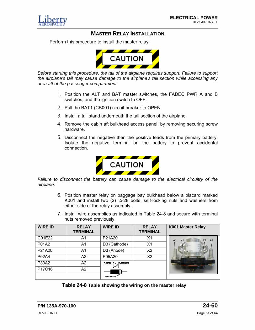
6. Position master relay on baggage bay bulkhead below a placard marked K001 and install two (2) ¼-28 bolts, self-locking nuts and washers from either side of the relay assembly.
7. Install wire assemblies as indicated in Table 24-8 and secure with terminal nuts removed previously.
WIRE ID RELAY TERMINAL
WIRE ID RELAY TERMINAL
K001 Master Relay
C01E22 A1 P21A20 X1 P01A2 A1 D3 (Cathode) X1 P21A20 A1 D3 (Anode) X2 P02A4 A2 P05A20 X2 P33A2 A2 P17C16 A2
Table 24-8 Table showing the wiring on the master relay
ELECTRICAL POWER XL-2 AIRPLANE
24-60 P/N 135A-970-100 Page 52 of 64 REVISION D
8. Reconnect positive then the negative cable to airplane’s primary battery. Apply a torque of 70 in-lb ± 5 in-lbs.
9. Install the aft baggage compartment closeout.
10. Press circuit breaker BAT 1 (CB001) to CLOSE.
11. Remove tail stand under the aircraft.
12. Perform operation check and inspection in the procedure Circuit Breaker and Master Relay Operation Check And Inspection on page 53 of this chapter.
This completes the Master Relay Installation procedure.
ELECTRICAL POWER XL-2 AIRCRAFT
P/N 135A-970-100 24-60 REVISION D Page 53 of 64
CIRCUIT BREAKER AND MASTER RELAY OPERATION CHECK AND INSPECTION
Perform the following procedure to do an operational check and inspection of the circuit breakers and master relay.
Refer to the Master Relay Troubleshooting Guide for corrective actions as required.
1. Verify primary battery is fully charged, Refer to Primary Battery Operation Check and Inspection procedure on page 35 of this chapter.
2. Position the aircraft in a designated run up area and set the parking brake. Push circuit breaker BAT 1 (CB001) to CLOSE.
3. Inspect circuit breakers for evidence of damage, open or “tripped” condition.
In the following steps, power will be applied to the DC power distribution system. If a circuit breaker trips when power is applied, discontinue the operation check procedure. Identify and correct cause of the trip prior to continuing. Refer to Table 24-10 for a guide to troubleshooting the DC power distribution.
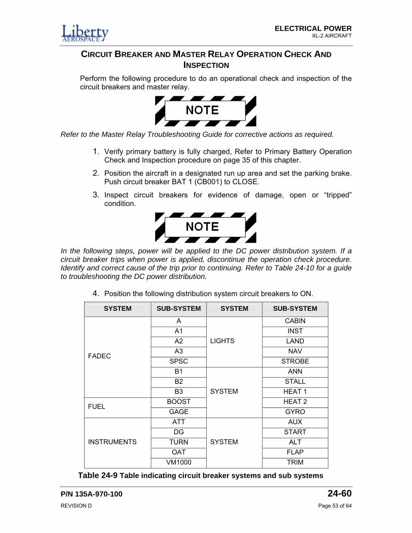
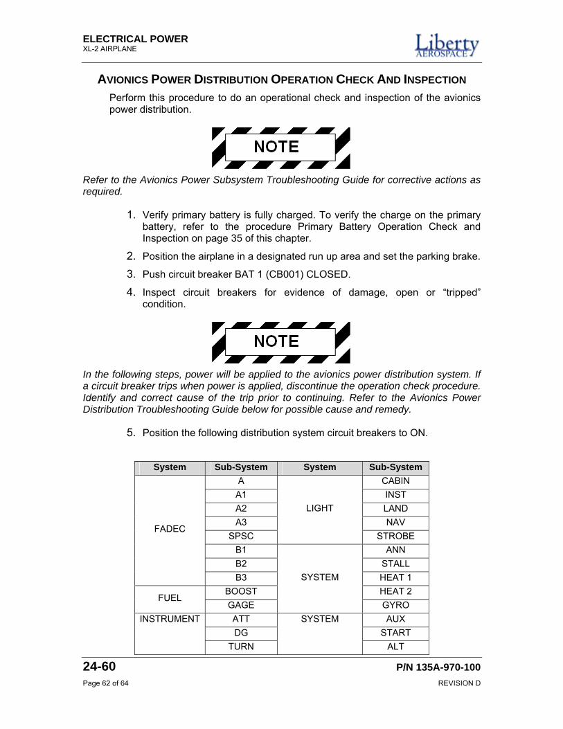
4. Position the following distribution system circuit breakers to ON.
SYSTEM SUB-SYSTEM SYSTEM SUB-SYSTEM
A CABIN A1 INST A2 LAND A3 NAV
SPSC
LIGHTS
STROBE B1 ANN B2 STALL
FADEC
B3 HEAT 1 BOOST HEAT 2
FUEL GAGE
SYSTEM
GYRO ATT AUX DG START
TURN ALT OAT FLAP
INSTRUMENTS
VM1000
SYSTEM
TRIM
Table 24-9 Table indicating circuit breaker systems and sub systems
ELECTRICAL POWER XL-2 AIRPLANE
24-60 P/N 135A-970-100 Page 54 of 64 REVISION D
5. Position the aircraft master switch to ON.
6. Verify the master relay engages.
7. Verify there is an indication of the correct battery voltage on the VM1000FX engine status display.
8. Power on each of the systems and subsystems listed in the table above. Verify that each of the systems or subsystems power on and the associated circuit breaker remains set.
9. Power off each of the systems and subsystems activated.
10. Using standard flight manual procedure, start the engine.
11. Set engine RPM to idle (850 to 950 RPM).
12. Power on each of the systems and subsystems listed in the table above not already activated. Verify that each of the systems or subsystems power on and the associated circuit breaker remains set.
13. After the oil temperature reaches 75 degrees, set throttle to 1700 RPM.
14. Verify each system and subsystem activated previously remains powered on and associated circuit breaker remains set.
15. Set throttle for idle (850-950 RPM).
16. Using standard flight manual procedures, secure selectable loads and shut down the engine.
17. Position the aircraft master switch to OFF.
This completes the Circuit Breaker and Master Relay Operation Check And Inspection procedure.
ELECTRICAL POWER XL-2 AIRCRAFT
P/N 135A-970-100 24-60 REVISION D Page 55 of 64
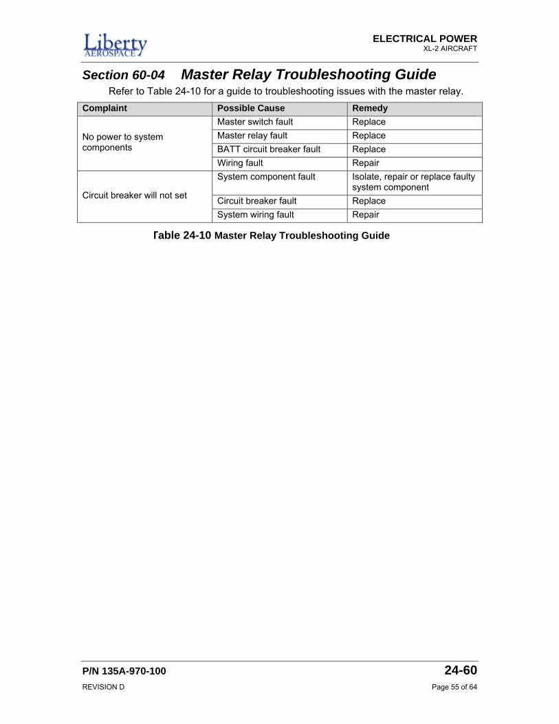
Section 60-04 Master Relay Troubleshooting Guide Refer to Table 24-10 for a guide to troubleshooting issues with the master relay.
Complaint Possible Cause Remedy Master switch fault Replace Master relay fault Replace BATT circuit breaker fault Replace
No power to system components
Wiring fault Repair System component fault Isolate, repair or replace faulty
system component Circuit breaker fault Replace Circuit breaker will not set
System wiring fault Repair
Table 24-10 Master Relay Troubleshooting Guide

ELECTRICAL POWER XL-2 AIRCRAFT
P/N 135A-970-100 24-60 REVISION D Page 57 of 64
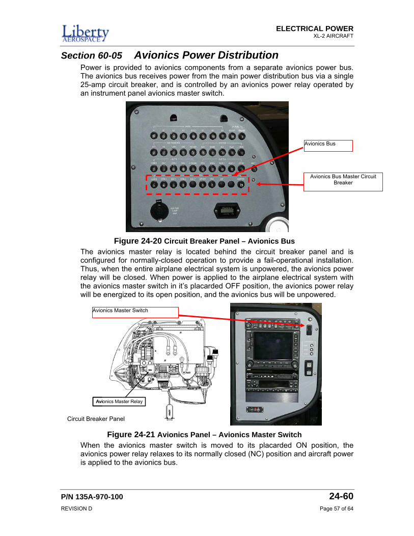
Section 60-05 Avionics Power Distribution Power is provided to avionics components from a separate avionics power bus. The avionics bus receives power from the main power distribution bus via a single 25-amp circuit breaker, and is controlled by an avionics power relay operated by an instrument panel avionics master switch.
The avionics master relay is located behind the circuit breaker panel and is configured for normally-closed operation to provide a fail-operational installation. Thus, when the entire airplane electrical system is unpowered, the avionics power relay will be closed. When power is applied to the airplane electrical system with the avionics master switch in it’s placarded OFF position, the avionics power relay will be energized to its open position, and the avionics bus will be unpowered.
Avionics Master RelayAvionics Master Relay
When the avionics master switch is moved to its placarded ON position, the avionics power relay relaxes to its normally closed (NC) position and aircraft power is applied to the avionics bus.
Figure 24-20 Circuit Breaker Panel – Avionics Bus
Figure 24-21 Avionics Panel – Avionics Master Switch
Avionics Master Switch
Circuit Breaker Panel
Avionics Bus
Avionics Bus Master Circuit Breaker
ELECTRICAL POWER XL-2 AIRPLANE
24-60 P/N 135A-970-100 Page 58 of 64 REVISION D
Section 60-06 Circuit Breaker Removal and Installation The circuit breakers for the avionics are the same as the other circuit breakers mounted to the CB (Circuit Breaker) panel. The procedures to remove and install the circuit breakers for the avionic panel are the same as the other circuit breakers. To remove any of the circuit breakers for the avionics panel, refer to the procedure Circuit Breaker Removal on page 46 of this chapter. To install any of the circuit breakers for the avionics panel, refer to the procedure Circuit Breaker Installation on page 48 of this chapter.
After installing a new avionics circuit breaker, perform an operational check and inspection per the procedure Avionics Power Distribution Operation Check And Inspection on page 62 of this chapter.
Section 60-07 Periodic Maintenance The system for the avionics power distribution does not require periodic maintenance cycles. In the event a fault condition is noted, perform an operational check and inspection per the procedure Avionics Power Distribution Operation Check And Inspection on page 62 of this chapter.
Section 60-08 Avionics Power Distribution Procedures This section details the removal, installation and inspections of the avionics master relay, K004, located on the rear side of the CB (Circuit Breaker) panel.
ELECTRICAL POWER XL-2 AIRCRAFT
P/N 135A-970-100 24-60 REVISION D Page 59 of 64
AVIONICS MASTER RELAY REMOVAL Perform this procedure to remove the avionics master relay.
1. Position the ALT and BAT master switches, the FADEC PWR A and B switches, and the ignition switch to OFF.
2. Pull the BAT1 (CB001) circuit breaker to OPEN.
3. Locate two post lamps installed near the upper panel edge and remove hoods. Set them aside for later installation.
4. Locate and remove seven (7) 8-32 machine screws securing the circuit breaker panel to the instrument console. Retain these screws for later installation.
The following step will remove the circuit breaker panel. There are a number of electrical wire harness connections to the instrument console and ground plane. Care must be taken to guide wire harnesses during the removal process in order to prevent damage.
5. Prepare a protective cushion surface just below and in front of the circuit breaker panel console position.
6. Gently pull the circuit breaker panel out of the instrument console and pivot face down in front of the console on the protective cushion surface.
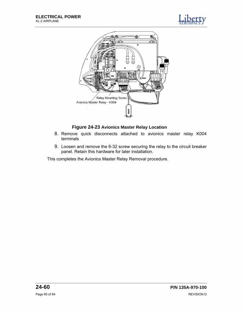
7. Locate avionics master relay, K004, on the circuit breaker panel rear assembly.
Figure 24-22 Circuit Breaker Panel
ELECTRICAL POWER XL-2 AIRPLANE
24-60 P/N 135A-970-100 Page 60 of 64 REVISION D
8. Remove quick disconnects attached to avionics master relay K004 terminals
9. Loosen and remove the 6-32 screw securing the relay to the circuit breaker panel. Retain this hardware for later installation.
This completes the Avionics Master Relay Removal procedure.
Figure 24-23 Avionics Master Relay Location
ELECTRICAL POWER XL-2 AIRCRAFT
P/N 135A-970-100 24-60 REVISION D Page 61 of 64
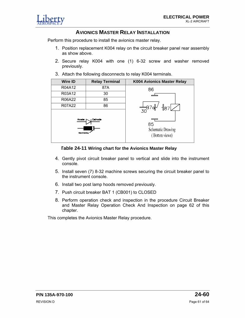
AVIONICS MASTER RELAY INSTALLATION Perform this procedure to install the avionics master relay.
1. Position replacement K004 relay on the circuit breaker panel rear assembly as show above.
2. Secure relay K004 with one (1) 6-32 screw and washer removed previously.
3. Attach the following disconnects to relay K004 terminals. Wire ID Relay Terminal K004 Avionics Master Relay R04A12 87A R03A12 30 R06A22 85 R07A22 86
4. Gently pivot circuit breaker panel to vertical and slide into the instrument console.
5. Install seven (7) 8-32 machine screws securing the circuit breaker panel to the instrument console.
6. Install two post lamp hoods removed previously.
7. Push circuit breaker BAT 1 (CB001) to CLOSED
8. Perform operation check and inspection in the procedure Circuit Breaker and Master Relay Operation Check And Inspection on page 62 of this chapter.
This completes the Avionics Master Relay procedure.
Table 24-11 Wiring chart for the Avionics Master Relay
ELECTRICAL POWER XL-2 AIRPLANE
24-60 P/N 135A-970-100 Page 62 of 64 REVISION D
AVIONICS POWER DISTRIBUTION OPERATION CHECK AND INSPECTION Perform this procedure to do an operational check and inspection of the avionics power distribution.
Refer to the Avionics Power Subsystem Troubleshooting Guide for corrective actions as required.
1. Verify primary battery is fully charged. To verify the charge on the primary battery, refer to the procedure Primary Battery Operation Check and Inspection on page 35 of this chapter.
2. Position the airplane in a designated run up area and set the parking brake.
3. Push circuit breaker BAT 1 (CB001) CLOSED.
4. Inspect circuit breakers for evidence of damage, open or “tripped” condition.
In the following steps, power will be applied to the avionics power distribution system. If a circuit breaker trips when power is applied, discontinue the operation check procedure. Identify and correct cause of the trip prior to continuing. Refer to the Avionics Power Distribution Troubleshooting Guide below for possible cause and remedy.
5. Position the following distribution system circuit breakers to ON.
System Sub-System System Sub-System
A CABIN A1 INST A2 LAND A3 NAV
SPSC
LIGHT
STROBE B1 ANN B2 STALL
FADEC
B3 HEAT 1 BOOST HEAT 2
FUEL GAGE
SYSTEM
GYRO ATT AUX DG START
INSTRUMENT
TURN
SYSTEM
ALT
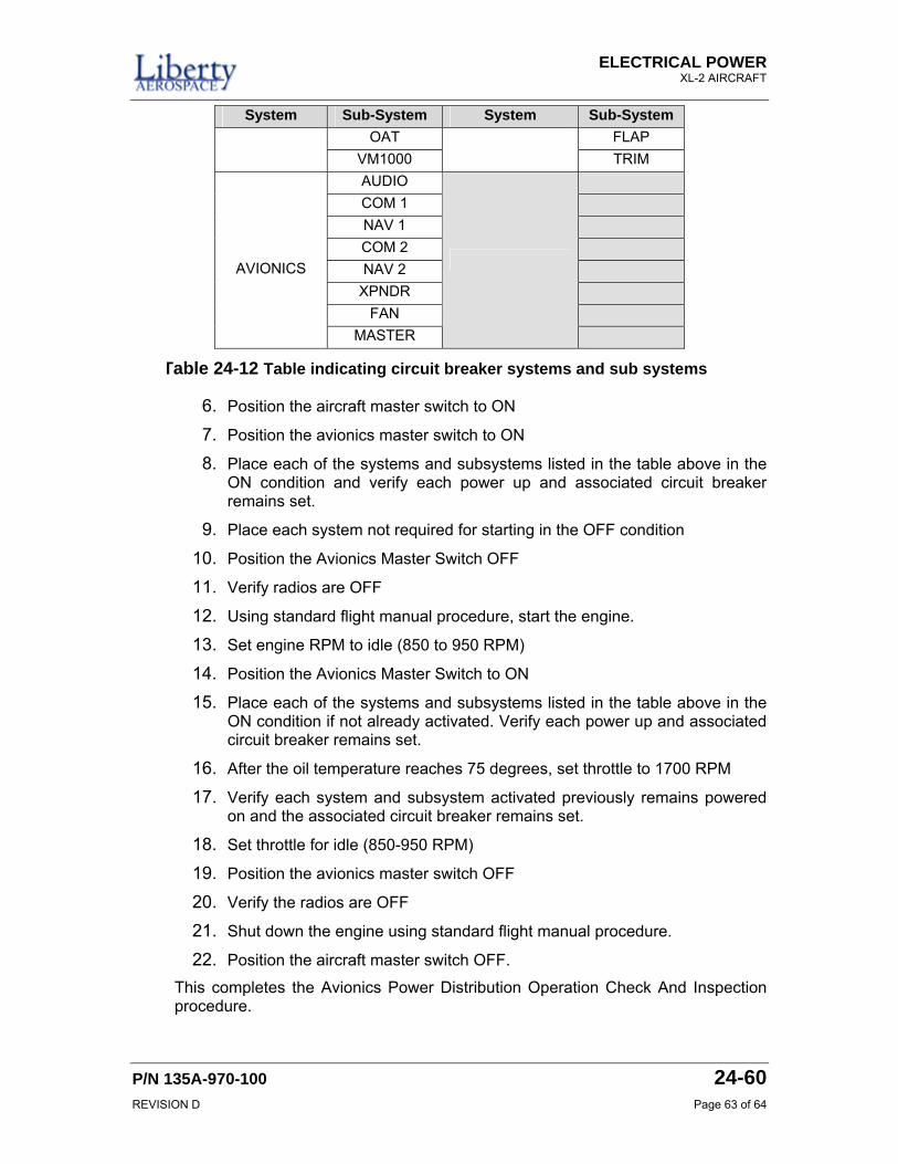
ELECTRICAL POWER XL-2 AIRCRAFT
P/N 135A-970-100 24-60 REVISION D Page 63 of 64
System Sub-System System Sub-System OAT FLAP
VM1000 TRIM AUDIO COM 1 NAV 1 COM 2 NAV 2
XPNDR FAN
AVIONICS
MASTER
6. Position the aircraft master switch to ON
7. Position the avionics master switch to ON
8. Place each of the systems and subsystems listed in the table above in the ON condition and verify each power up and associated circuit breaker remains set.
9. Place each system not required for starting in the OFF condition
10. Position the Avionics Master Switch OFF
11. Verify radios are OFF
12. Using standard flight manual procedure, start the engine.
13. Set engine RPM to idle (850 to 950 RPM)
14. Position the Avionics Master Switch to ON
15. Place each of the systems and subsystems listed in the table above in the ON condition if not already activated. Verify each power up and associated circuit breaker remains set.
16. After the oil temperature reaches 75 degrees, set throttle to 1700 RPM
17. Verify each system and subsystem activated previously remains powered on and the associated circuit breaker remains set.
18. Set throttle for idle (850-950 RPM)
19. Position the avionics master switch OFF
20. Verify the radios are OFF
21. Shut down the engine using standard flight manual procedure.
22. Position the aircraft master switch OFF.
This completes the Avionics Power Distribution Operation Check And Inspection procedure.
Table 24-12 Table indicating circuit breaker systems and sub systems
ELECTRICAL POWER XL-2 AIRPLANE
24-60 P/N 135A-970-100 Page 64 of 64 REVISION D
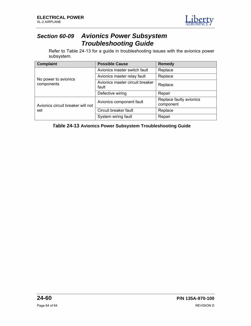
Section 60-09 Avionics Power Subsystem Troubleshooting Guide
Refer to Table 24-13 for a guide in troubleshooting issues with the avionics power subsystem.
Complaint Possible Cause Remedy Avionics master switch fault Replace Avionics master relay fault Replace Avionics master circuit breaker fault Replace
No power to avionics components
Defective wiring Repair
Avionics component fault Replace faulty avionics component
Circuit breaker fault Replace Avionics circuit breaker will not set
System wiring fault Repair
Table 24-13 Avionics Power Subsystem Troubleshooting Guide


![B Recommended hole pattern: [mm] D1 Electrical …docs-europe.electrocomponents.com/webdocs/135a/0900766b8135aef0.pdf1.5 Charge and Discharge Frequent and quick charge / discharge](https://img.pdfslide.net/doc/110x75/5abcf25c7f8b9a297f8eafdd/b-recommended-hole-pattern-mm-d1-electrical-docs-charge-and-discharge-frequent.jpg)