Embed Size (px)
Citation preview

Lancair International Inc., Represented by Neico Aviation Inc., Copyright 2008 Redmond, OR 97756
Chapter 24 Page 24.1 REV. 2nd Ed./08-15-2006Odds and EndsES
1 Introduction chapter covers the construction of those parts that just didn't fit into other chapters. This des the following:onnecting the fresh air vent to the overhead console
nstalling the pitot/static port and tubingnstalling the door seal pumpetting the flap micro switches
3/04-30-2008
Chapter 24 Odds and Ends 24.Thisinclu
• C• I• I• S
24.1 Introduction . . . . . . . . . . . . . . . . . . . . . . . . . . . . . . . . . . . . . . 24.124.2 Parts List . . . . . . . . . . . . . . . . . . . . . . . . . . . . . . . . . . . . . . . . 24.224.3 Construction Procedures. . . . . . . . . . . . . . . . . . . . . . . . . . . . 24.3
24.3.A Completing the Fresh Air Vent . . . . . . . . . . . . . . . . . . . 24.324.3.B Completing the Pitot/Static Installation . . . . . . . . . . . . . 24.624.3.C Installing the Door Seal Pump. . . . . . . . . . . . . . . . . . . . 24.11
24.3.D Setting the Flap Micro Switches . . . . . . . . . . . . . . . . . . . . 24.13
Lancair International Inc., Represented by Neico Aviation Inc., Copyright 2008 Redmond, OR 97756
Chapter 24 Page 24.2 REV. 2nd Ed./08-15-2006Odds and EndsES
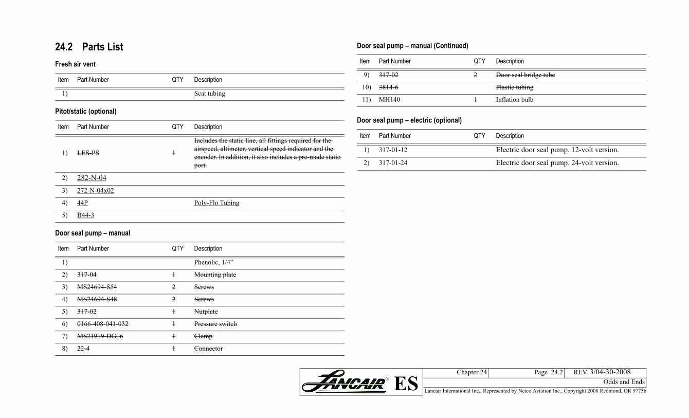
317-02 2 Door seal bridge tube
3814-6 Plastic tubing
MH140 1 Inflation bulb
seal pump – electric (optional)
Part Number QTY Description
317-01-12 Electric door seal pump. 12-volt version.
317-01-24 Electric door seal pump. 24-volt version.
seal pump – manual (Continued)
Part Number QTY Description
3/04-30-2008
8) 22-4 1 Connector
24.2 Parts List Fresh air vent
Item Part Number QTY Description
1) Scat tubing
Pitot/static (optional)
Item Part Number QTY Description
1) LES-PS 1
Includes the static line, all fittings required for the airspeed, altimeter, vertical speed indicator and the encoder. In addition, it also includes a pre-made static port.
2) 282-N-04
3) 272-N-04x02
4) 44P Poly-Flo Tubing
5) B44-3
Door seal pump – manual
Item Part Number QTY Description
1) Phenolic, 1/4”
2) 317-04 1 Mounting plate
3) MS24694-S54 2 Screws
4) MS24694-S48 2 Screws
5) 317-02 1 Nutplate
6) 0166-408-041-032 1 Pressure switch
7) MS21919-DG16 1 Clamp
9)
10)
11)
Door
Item
1)
2)
Door
Item

Lancair International Inc., Represented by Neico Aviation Inc., Copyright 2008 Redmond, OR 97756
Chapter 24 Page 24.3 REV. 2nd Ed./08-15-2006Odds and EndsES
esh air flange
24.3 Construction Procedures24.3.A Completing the Fresh Air VentThe fresh air that enters through the NACA scoop needs to be moved to the overhead console. As air enters the NACA scoop it becomes slightly pressurized in the plenum chamber formed by the forward and aft vertical stabilizer webs. The air is then pushed forward to the overhead console through a 3" (75 mm) diameter flexible Scat tube. The tubing runs from the scoop to the overhead console.Before you can install the tubing, a flange is needed on the console to attach to the tubing.In this section you will make the flange using a 12 oz. soft drink can. A soft drink can has a 2.6” diameter, just the size you need to form a flange for the tubing.Steps...1. Cut off the bottom 1/2” (13 mm) of an empty soft drinkcan. (Beer cans will also work well.)2. Apply four layers of duct tape to the soft drink can to act
as a release for the fiberglass flange.The duct tape also gives the flange the slightly larger diameter needed for the Scat tubing.
3. Apply a layer of release tape to a flat surface. A table top or a piece of aluminum will work.
4. Using instant glue, tack the soft drink can to the flat release surface as shown in Figure 15:G:3.
5. Lay up a flange with 4-BID by applying 1-BID at a time, covering half the perimeter of the can at a time.Don't try to wrap the 4-BID all the way around the can in one step. It is easier to apply 1-BID at a time.Tip: Alternate the location of the BID-tape junctions from layer to layer.
Figure 24.3.A.1 Soda can as basis for fr
Lancair International Inc., Represented by Neico Aviation Inc., Copyright 2008 Redmond, OR 97756
Chapter 24 Page 24.4 REV. 2nd Ed./08-15-2006Odds and EndsES
uselage top
onsole
op
console
de from
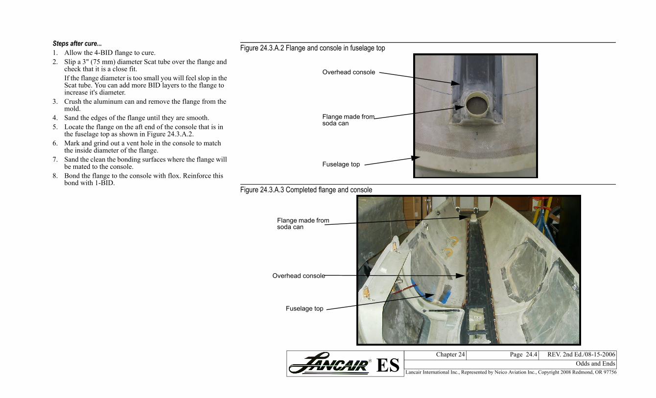
Steps after cure...1. Allow the 4-BID flange to cure.2. Slip a 3" (75 mm) diameter Scat tube over the flange and
check that it is a close fit.If the flange diameter is too small you will feel slop in the Scat tube. You can add more BID layers to the flange to increase it's diameter.
3. Crush the aluminum can and remove the flange from the mold.
4. Sand the edges of the flange until they are smooth.5. Locate the flange on the aft end of the console that is in
the fuselage top as shown in Figure 24.3.A.2.6. Mark and grind out a vent hole in the console to match
the inside diameter of the flange.7. Sand the clean the bonding surfaces where the flange will
be mated to the console.8. Bond the flange to the console with flox. Reinforce this
bond with 1-BID.
Figure 24.3.A.2 Flange and console in f
Figure 24.3.A.3 Completed flange and c
Fuselage t
Overhead
Flange masoda can
Fuselage top
Overhead console
Flange made from soda can
Lancair International Inc., Represented by Neico Aviation Inc., Copyright 2008 Redmond, OR 97756
Chapter 24 Page 24.5 REV. 2nd Ed./08-15-2006Odds and EndsES
ing for the fresh air vent
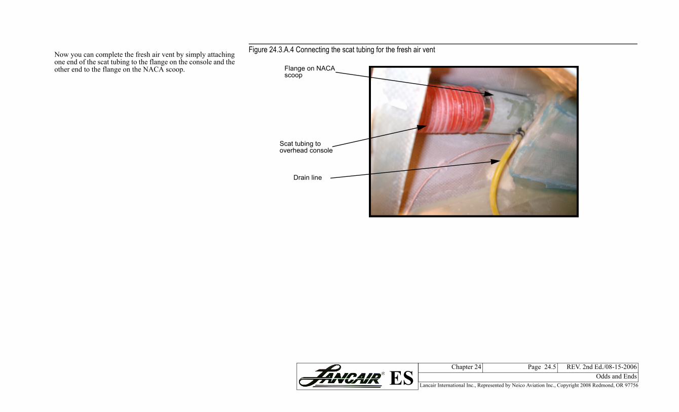
Now you can complete the fresh air vent by simply attaching one end of the scat tubing to the flange on the console and the other end to the flange on the NACA scoop.Figure 24.3.A.4 Connecting the scat tub
Drain line
Scat tubing to overhead console
Flange on NACA scoop
Lancair International Inc., Represented by Neico Aviation Inc., Copyright 2008 Redmond, OR 97756
Chapter 24 Page 24.6 REV. 2nd Ed./08-15-2006Odds and EndsES
tic system
3/04-30-2008
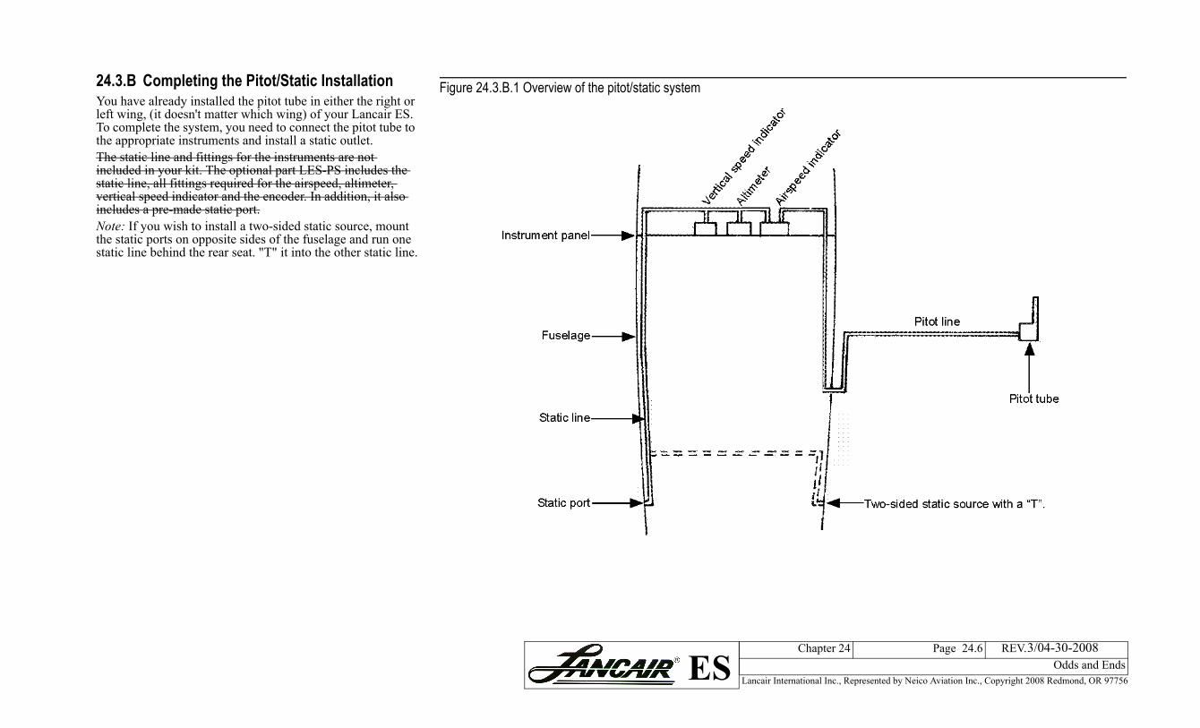
24.3.B Completing the Pitot/Static InstallationYou have already installed the pitot tube in either the right or left wing, (it doesn't matter which wing) of your Lancair ES. To complete the system, you need to connect the pitot tube to the appropriate instruments and install a static outlet.The static line and fittings for the instruments are not included in your kit. The optional part LES-PS includes the static line, all fittings required for the airspeed, altimeter, vertical speed indicator and the encoder. In addition, it also includes a pre-made static port.Note: If you wish to install a two-sided static source, mount the static ports on opposite sides of the fuselage and run one static line behind the rear seat. "T" it into the other static line.
Figure 24.3.B.1 Overview of the pitot/sta
Lancair International Inc., Represented by Neico Aviation Inc., Copyright 2008 Redmond, OR 97756
Chapter 24 Page 24.7 REV. 2nd Ed./08-15-2006Odds and EndsES
tatic system
3/04-30-2008
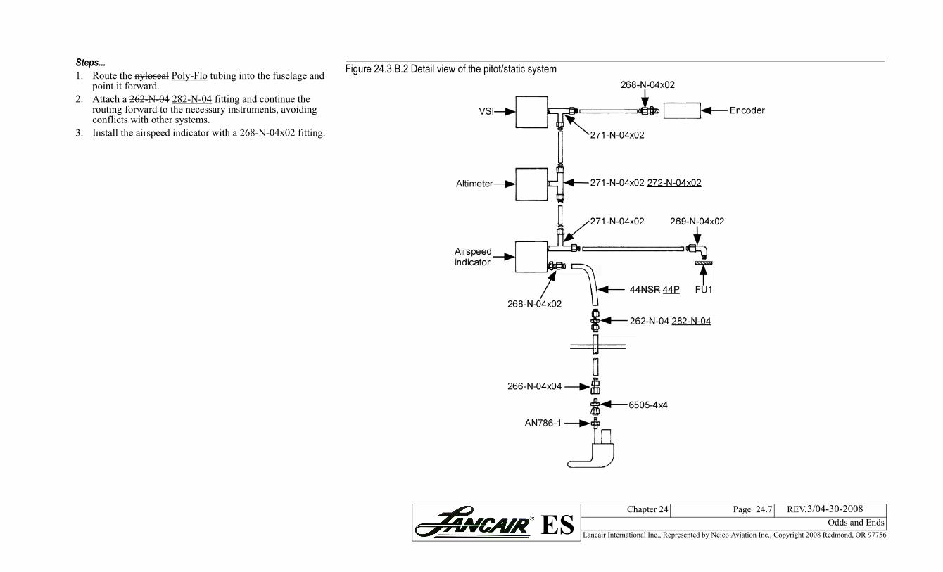
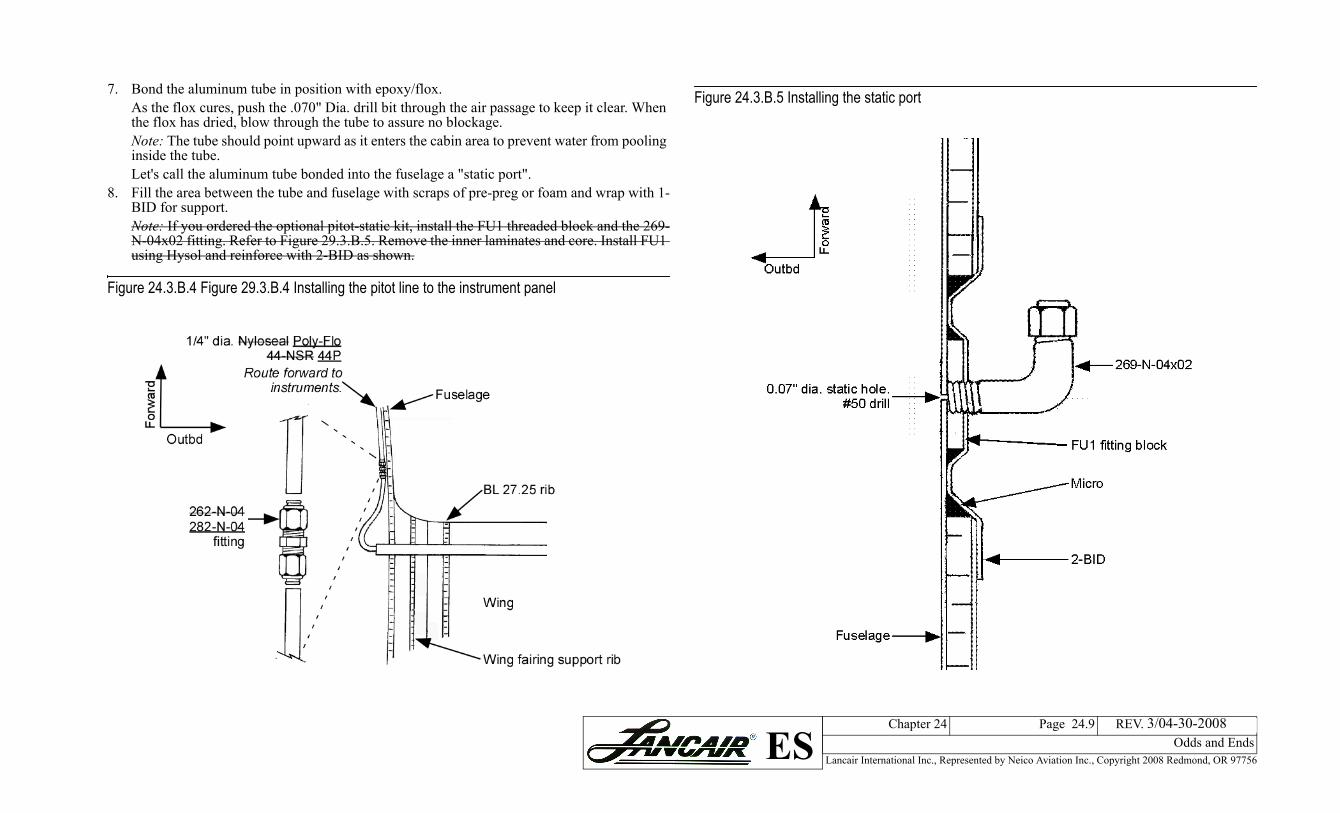
Steps...1. Route the nyloseal Poly-Flo tubing into the fuselage and
point it forward.2. Attach a 262-N-04 282-N-04 fitting and continue the
routing forward to the necessary instruments, avoiding conflicts with other systems.
3. Install the airspeed indicator with a 268-N-04x02 fitting.
Figure 24.3.B.2 Detail view of the pitot/s
Lancair International Inc., Represented by Neico Aviation Inc., Copyright 2008 Redmond, OR 97756
Chapter 24 Page 24.8 REV. 2nd Ed./08-15-2006Odds and EndsES
lage side
uteHole location in fuselage
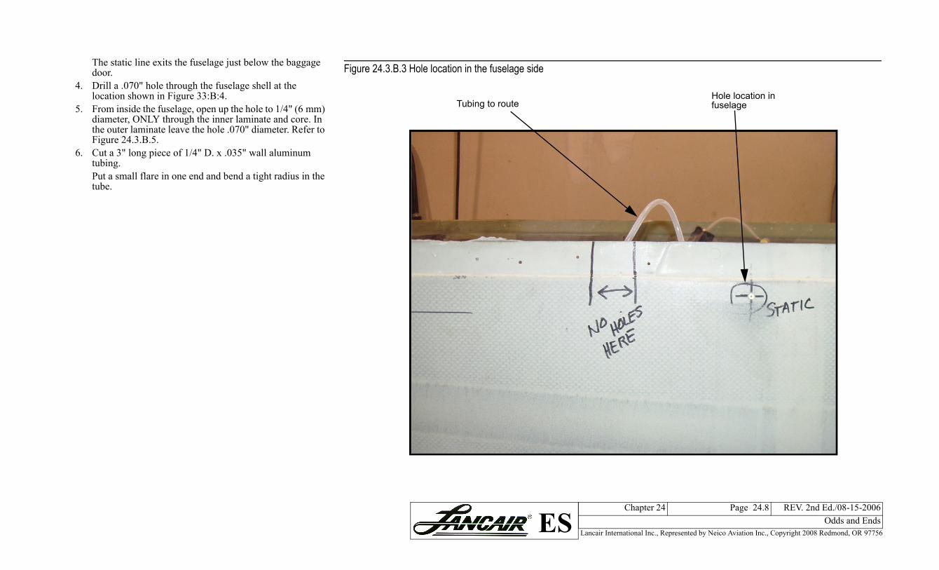
The static line exits the fuselage just below the baggage door.
4. Drill a .070" hole through the fuselage shell at the location shown in Figure 33:B:4.
5. From inside the fuselage, open up the hole to 1/4" (6 mm) diameter, ONLY through the inner laminate and core. In the outer laminate leave the hole .070" diameter. Refer to Figure 24.3.B.5.
6. Cut a 3" long piece of 1/4" D. x .035" wall aluminum tubing.Put a small flare in one end and bend a tight radius in the tube.
Figure 24.3.B.3 Hole location in the fuse
Tubing to ro
Lancair International Inc., Represented by Neico Aviation Inc., Copyright 2008 Redmond, OR 97756
Chapter 24 Page 24.9 REV. 2nd Ed./08-15-2006Odds and EndsES
re 24.3.B.5 Installing the static port
3/04-30-2008
7. Bond the aluminum tube in position with epoxy/flox.As the flox cures, push the .070" Dia. drill bit through the air passage to keep it clear. When the flox has dried, blow through the tube to assure no blockage.Note: The tube should point upward as it enters the cabin area to prevent water from pooling inside the tube. Let's call the aluminum tube bonded into the fuselage a "static port".
8. Fill the area between the tube and fuselage with scraps of pre-preg or foam and wrap with 1-BID for support.Note: If you ordered the optional pitot-static kit, install the FU1 threaded block and the 269-N-04x02 fitting. Refer to Figure 29.3.B.5. Remove the inner laminates and core. Install FU1 using Hysol and reinforce with 2-BID as shown.
Figure 24.3.B.4 Figure 29.3.B.4 Installing the pitot line to the instrument panel
Figu
Lancair International Inc., Represented by Neico Aviation Inc., Copyright 2008 Redmond, OR 97756
Chapter 24 Page 24.10 REV. 2nd Ed./08-15-2006Odds and EndsES
3/04-30-2008
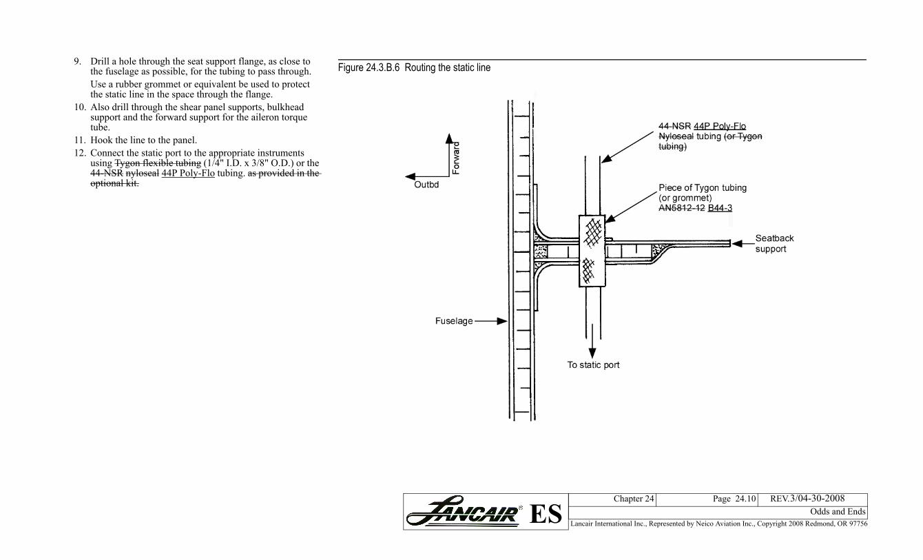
9. Drill a hole through the seat support flange, as close to the fuselage as possible, for the tubing to pass through.Use a rubber grommet or equivalent be used to protect the static line in the space through the flange.
10. Also drill through the shear panel supports, bulkhead support and the forward support for the aileron torque tube.
11. Hook the line to the panel. 12. Connect the static port to the appropriate instruments
using Tygon flexible tubing (1/4" I.D. x 3/8" O.D.) or the 44-NSR nyloseal 44P Poly-Flo tubing. as provided in the optional kit.
Figure 24.3.B.6 Routing the static line
Lancair International Inc., Represented by Neico Aviation Inc., Copyright 2008 Redmond, OR 97756
Chapter 24 Page 24.11 REV. 2nd Ed./08-15-2006Odds and EndsES
pump to the left fuselage side
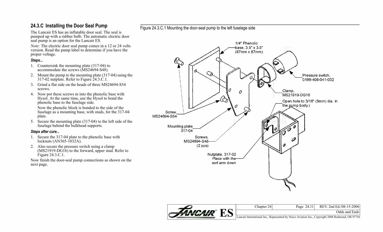
24.3.C Installing the Door Seal PumpThe Lancair ES has an inflatable door seal. The seal is pumped up with a rubber bulb. The automatic electric door seal pump is an option for the Lancair ES.Note: The electric door seal pump comes in a 12 or 24 volts version. Read the pump label to determine if you have the proper voltage.Steps...1. Countersink the mounting plate (317-04) toaccommodate the screws (MS24694-S48).2. Mount the pump to the mounting plate (317-04) using the
317-02 nutplate. Refer to Figure 24.3.C.1.3. Grind a flat side on the heads of three MS24694-S54
screws.4. Now pot these screws m into the phenolic base with
Hysol. At the same time, use the Hysol to bond the phenolic base to the fuselage side.Now the phenolic block is bonded to the side of the fuselage as a mounting base, with studs, for the 317-04 plate.
5. Secure the mounting plate (317-04) to the left side of the fuselage behind the bulkhead supports.
Steps after cure...1. Secure the 317-04 plate to the phenolic base with
locknuts (AN365-1032A).2. Also secure the pressure switch using a clamp
(MS21919-DG16) to the forward, upper stud. Refer to Figure 24.3.C.1.
Now finish the door-seal pump connections as shown on the next page.
Figure 24.3.C.1 Mounting the door-seal
Lancair International Inc., Represented by Neico Aviation Inc., Copyright 2008 Redmond, OR 97756
Chapter 24 Page 24.12 REV. 2nd Ed./08-15-2006Odds and EndsES
re 24.3.C.3 Door seal pump hookup (electric)
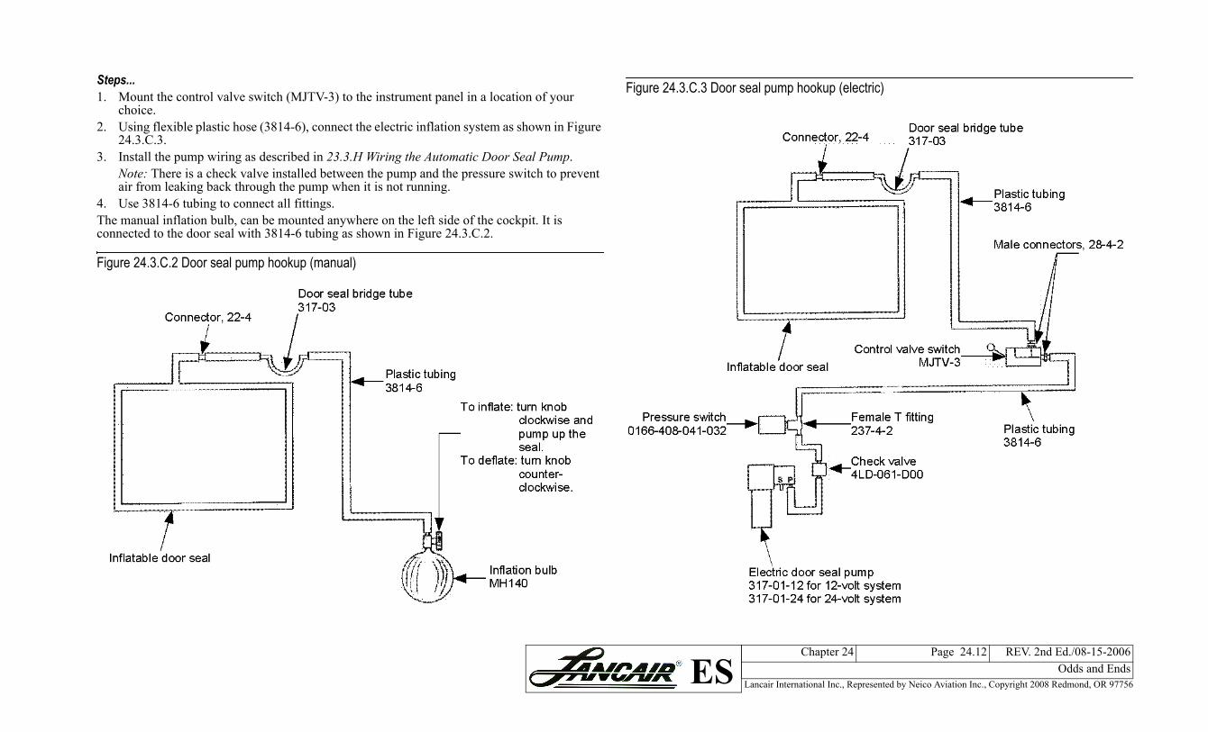
Steps...1. Mount the control valve switch (MJTV-3) to the instrument panel in a location of yourchoice.2. Using flexible plastic hose (3814-6), connect the electric inflation system as shown in Figure
24.3.C.3.3. Install the pump wiring as described in 23.3.H Wiring the Automatic Door Seal Pump.
Note: There is a check valve installed between the pump and the pressure switch to prevent air from leaking back through the pump when it is not running.
4. Use 3814-6 tubing to connect all fittings.The manual inflation bulb, can be mounted anywhere on the left side of the cockpit. It is connected to the door seal with 3814-6 tubing as shown in Figure 24.3.C.2.
Figure 24.3.C.2 Door seal pump hookup (manual)
Figu
Lancair International Inc., Represented by Neico Aviation Inc., Copyright 2008 Redmond, OR 97756
Chapter 24 Page 24.13 REV. 2nd Ed./08-15-2006Odds and EndsES
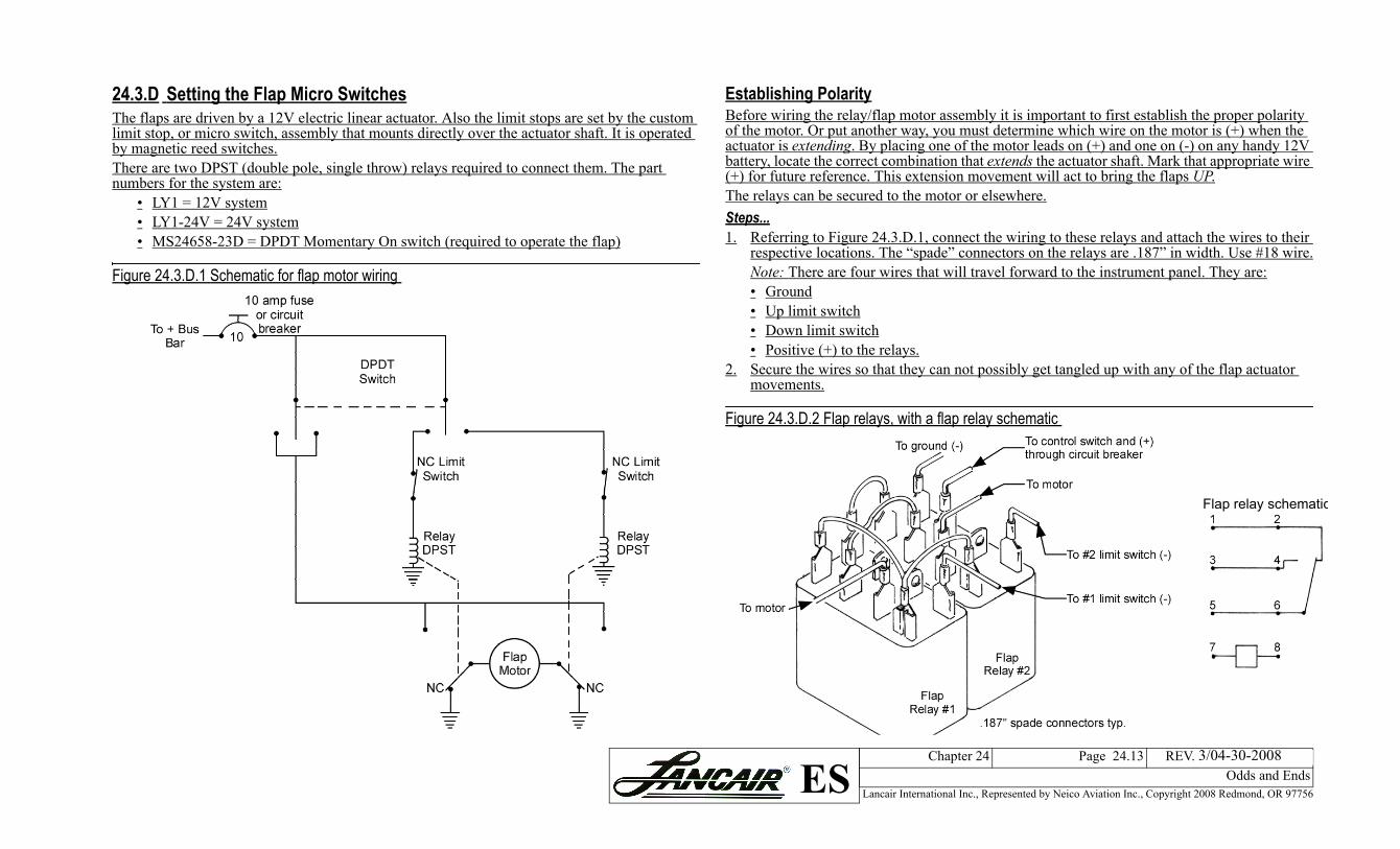
blishing Polarityre wiring the relay/flap motor assembly it is important to first establish the proper polarity e motor. Or put another way, you must determine which wire on the motor is (+) when the ator is extending. By placing one of the motor leads on (+) and one on (-) on any handy 12V ry, locate the correct combination that extends the actuator shaft. Mark that appropriate wire or future reference. This extension movement will act to bring the flaps UP.relays can be secured to the motor or elsewhere.s...
eferring to Figure 24.3.D.1, connect the wiring to these relays and attach the wires to their espective locations. The “spade” connectors on the relays are .187” in width. Use #18 wire.ote: There are four wires that will travel forward to the instrument panel. They are:GroundUp limit switchDown limit switchPositive (+) to the relays.
ecure the wires so that they can not possibly get tangled up with any of the flap actuator ovements.
re 24.3.D.2 Flap relays, with a flap relay schematic
Flap relay schematic
3/04-30-2008
24.3.D Setting the Flap Micro SwitchesThe flaps are driven by a 12V electric linear actuator. Also the limit stops are set by the custom limit stop, or micro switch, assembly that mounts directly over the actuator shaft. It is operated by magnetic reed switches.There are two DPST (double pole, single throw) relays required to connect them. The part numbers for the system are:
• LY1 = 12V system• LY1-24V = 24V system• MS24658-23D = DPDT Momentary On switch (required to operate the flap)
Figure 24.3.D.1 Schematic for flap motor wiring
EstaBefoof thactubatte(+) fThe Step1. R
rN••••
2. Sm
Figu
Lancair International Inc., Represented by Neico Aviation Inc., Copyright 2008 Redmond, OR 97756
Chapter 24 Page 24.14 REV. 2nd Ed./08-15-2006Odds and EndsES
3/04-30-2008
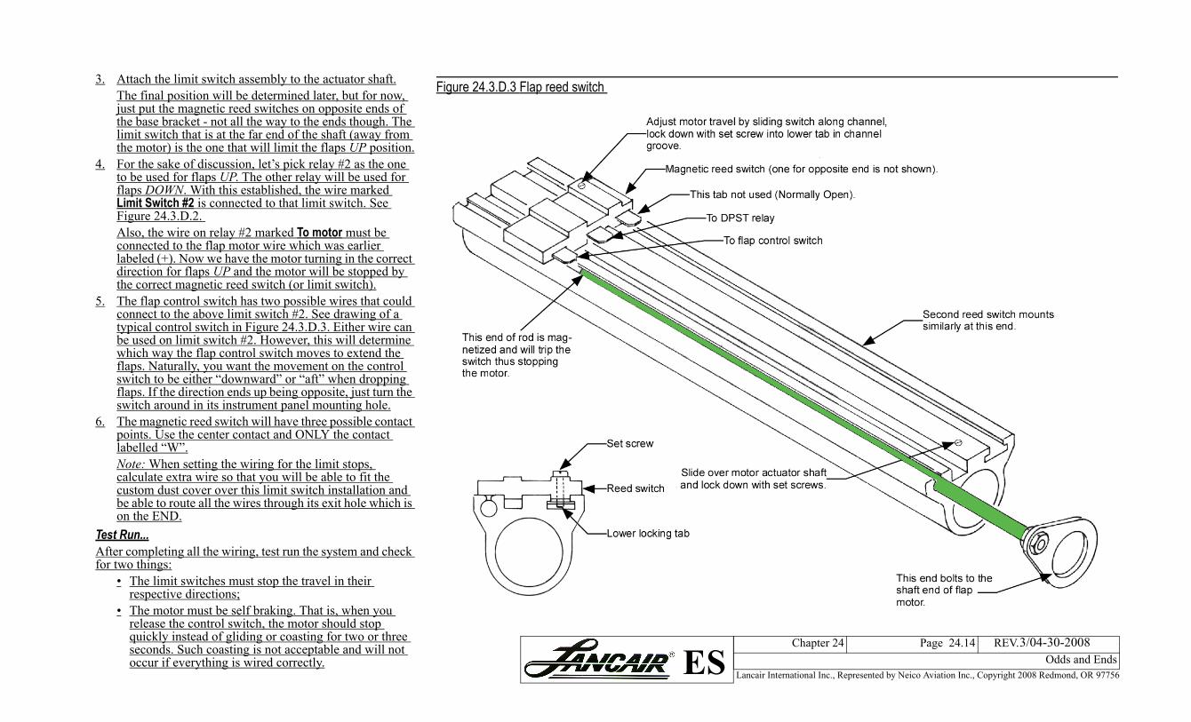
3. Attach the limit switch assembly to the actuator shaft.The final position will be determined later, but for now, just put the magnetic reed switches on opposite ends of the base bracket - not all the way to the ends though. The limit switch that is at the far end of the shaft (away from the motor) is the one that will limit the flaps UP position.
4. For the sake of discussion, let’s pick relay #2 as the one to be used for flaps UP. The other relay will be used for flaps DOWN. With this established, the wire marked Limit Switch #2 is connected to that limit switch. See Figure 24.3.D.2. Also, the wire on relay #2 marked To motor must be connected to the flap motor wire which was earlier labeled (+). Now we have the motor turning in the correct direction for flaps UP and the motor will be stopped by the correct magnetic reed switch (or limit switch).
5. The flap control switch has two possible wires that could connect to the above limit switch #2. See drawing of a typical control switch in Figure 24.3.D.3. Either wire can be used on limit switch #2. However, this will determine which way the flap control switch moves to extend the flaps. Naturally, you want the movement on the control switch to be either “downward” or “aft” when dropping flaps. If the direction ends up being opposite, just turn the switch around in its instrument panel mounting hole.
6. The magnetic reed switch will have three possible contact points. Use the center contact and ONLY the contact labelled “W”.Note: When setting the wiring for the limit stops, calculate extra wire so that you will be able to fit the custom dust cover over this limit switch installation and be able to route all the wires through its exit hole which is on the END.
Test Run...After completing all the wiring, test run the system and check for two things:
• The limit switches must stop the travel in their respective directions;
• The motor must be self braking. That is, when you release the control switch, the motor should stop quickly instead of gliding or coasting for two or three seconds. Such coasting is not acceptable and will not occur if everything is wired correctly.
Figure 24.3.D.3 Flap reed switch