Embed Size (px)
Citation preview
26Mechanical and
TribologicalRequirements and
Evaluation ofCoating Composites
26.1 IntroductionCoating Composites • Typical Mechanisms of Coating Composite Failure • Tribological Coatings of Today
26.2 Design of Tribological CoatingsCurrent Designs of Coating Structures • Coatings of Tomorrow
26.3 Design of Coated ComponentsGeneral Design Considerations • Design Considerations for Cutting Tools • Design Considerations for Forming Tools and Machine Components
26.4 Evaluation of Coating CompositesImportant Parameters • Adhesion to the Substrate • Basic Coating Properties • Intrinsic Mechanical Properties • Tribological Properties • Tribological Response of Coated Components • Failure Analysis of Coating Composites
26.5 Visions and Conclusions
26.1 Introduction
Coatings are increasingly being used to improve the tribological properties of mechanical componentssuch as tools for metal cutting and forming, and machine elements such as sliding bearings, seals, andvalves. This chapter presents tribological requirements and design considerations in the development ofcoating composites, and recommends methods and techniques for their evaluation. It is aimed both forthose involved in development of coatings and for the practicing tribology engineer.
Current concepts of coating composites used in cutting tools, forming tools, and machine elementsare reviewed, and the respective requirements addressed within each category are summarized. Conceptsof coatings designed for tools and machine elements are exemplified.
Further, it is demonstrated how the tribological properties of coating composites are related to thefundamental coating properties (chemical, thermal, mechanical); the general coating characteristics such
Sture HogmarkUppsala University
Staffan JacobsonUppsala University
Mats LarssonBalzers Sandvik Coating AB
Urban WiklundUppsala University
as composition and microstructure, topography, and thickness; and different aspects of the substratematerial. The important tribological phenomena discussed include:
• premature failures such as coating detachment, permanent surface deformation, cracking andspalling, occasional scratching, and material pickup
• gradual coating removal, including abrasive, erosive, and tribochemical wear.
Techniques to evaluate some of the more important fundamental and tribological properties arepresented, and several examples are given, mainly with thin physical vapor deposition (PVD) coatings.The evaluation techniques can be utilized both in coatings selection and development of future coatings.The chapter concludes with some recent trends and speculations about the future.
26.1.1 Coating Composites
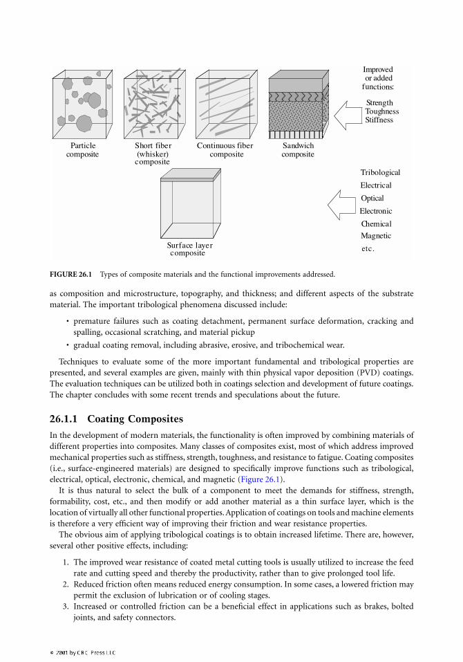
In the development of modern materials, the functionality is often improved by combining materials ofdifferent properties into composites. Many classes of composites exist, most of which address improvedmechanical properties such as stiffness, strength, toughness, and resistance to fatigue. Coating composites(i.e., surface-engineered materials) are designed to specifically improve functions such as tribological,electrical, optical, electronic, chemical, and magnetic (Figure 26.1).
It is thus natural to select the bulk of a component to meet the demands for stiffness, strength,formability, cost, etc., and then modify or add another material as a thin surface layer, which is thelocation of virtually all other functional properties. Application of coatings on tools and machine elementsis therefore a very efficient way of improving their friction and wear resistance properties.
The obvious aim of applying tribological coatings is to obtain increased lifetime. There are, however,several other positive effects, including:
1. The improved wear resistance of coated metal cutting tools is usually utilized to increase the feedrate and cutting speed and thereby the productivity, rather than to give prolonged tool life.
2. Reduced friction often means reduced energy consumption. In some cases, a lowered friction maypermit the exclusion of lubrication or of cooling stages.
3. Increased or controlled friction can be a beneficial effect in applications such as brakes, boltedjoints, and safety connectors.
FIGURE 26.1 Types of composite materials and the functional improvements addressed.
4. Reduced tendency to sticking and material pickup from the countersurface is crucial for theperformance of forming tools and in many sliding applications. Antisticking agents can be omittedin forming tool applications.
5. Components of reduced weight can be designed by application of coatings. Reduced weight means,for example, an increased ratio of power to weight of car engines, which in turn can give lowerfuel consumption.
There are also some limitations in thin coating application:
1. The coating process often involves significant heating of the substrate. This restricts the numberof potential substrate materials.
2. There is always a risk of galvanic corrosion associated with applying a coating to a metallicsubstrate.
3. Good tribological performance often requires high levels of hardness and stiffness of the substratematerial, because the thickness of PVD and CVD coatings is so limited that they normally needfirm support.
4. The PVD process has a limited ability to coat complicated geometries because it, in principle, isa line-of-sight method.
5. Finally, it should be noted that premature coating failure due to poor adhesion to the substrateor cracking and spalling of the coating material can be disastrous because loose coating fragmentsin many applications can aggravate the wear. Examples of components that may be at high riskto these phenomena include journal bearings, ball bearings, gears, and piston/cylinder systems.
The rapid development of new coating technologies thus has led to an accelerated increase in the useof coated tools and other components during the last couple of decades. This chapter is primarilyrestricted to thin (1 to 10 µm) physical vapor deposited (PVD) and chemical vapor deposited (CVD)coatings.
26.1.2 Typical Mechanisms of Coating Composite Failure
It is important to realize that the mechanical contact between solids is localized to a number of microscalecontact spots that together form the real area of contact. Irrespective of the nominal (or geometrical)contact area, a good estimate of the real contact area is obtained by dividing the normal load by thehardness of the softer of the two mating surfaces. In other words, the contact pressure in these tiny areasis of the order of their hardness. Bearing this in mind, it is not surprising that damage can occur, evenin apparently very mildly loaded tribological contacts. One such example is the damage that occurs whensliding ceramic seals against each other despite the nominal contact pressure being 100,000 times lowerthan their hardness (Blomberg et al., 1994; Hogmark et al., 1992b).
The wear resistance of a coated component is mainly determined by the coating as long as it coversthe contact area. As soon as the coating is partly worn through, or the substrate is exposed due to adhesivefailure or cracking and spalling, the wear resistance of the substrate material becomes important. An in-depth description of the large number of wear mechanisms found in the applications of coated compo-nents is given in Holmberg and Matthews (1994).
Characteristic of coating composites as to their modes of failure is the inhomogeneity of the surfacelayer due to the presence of the coating. There is often a large difference in mechanical, thermal, andchemical properties between the coating and substrate materials, and the interface between them oftenrepresents a steep discontinuity in these properties.
There are principally two modes by which a coating composite may fail:
1. premature failure2. failure due to gradual wear
If the wear resistance of the coating is high and the coating wears down gradually, a considerableprolongation in life can be experienced as compared to that of an uncoated reference, even if the coating

is thin (Figure 26.2). On the other hand, if the coating fails prematurely due to poor adhesion or crackingand spalling, the lifetime may even be shortened, because coating wear debris entrapped in the contactinterface can aggravate the wear of the substrate material.
It is clear from Figure 26.2 that increasing the coating thickness will prolong the lifetime as long asthe wear rate is gradual and steady. However, as will be further elucidated in Section 26.4.4.2, the thicknessof PVD and CVD coatings is restricted by their internal stresses, which build up in the coating duringdeposition. Therefore, the coating is often very thin compared with the tolerable wear depth. Conse-quently, in addition to displaying sufficient adhesion and resistance against cracking and spalling, thecoating must be extremely wear resistant in order to considerably improve the tribological properties ofthe coating composite.
Often, premature coating failure ends the life of well-functioning components after a period of gradualwear. In contrast to failure due to gradual coating wear, premature coating failure is very difficult topredict — both experimentally and theoretically.
Some of the more important mechanisms of coating failure are summarized in Figure 26.3.
26.1.2.1 Premature Failure
Premature failure designates a situation where the full tribological potential of the coating is not gained(see Figures 26.2 and 26.4). Instead, the component fails due to one or several of the following reasons:
1. coating detachment2. permanent deformation of the coating composite3. cracking and spalling of the coating4. pickup of material from the countersurface
In general, tribological applications put higher demands on the coating adhesion than any other areaof application, although the demands can differ substantially from one tribological situation to the other.It is instructive to distinguish between the actual adhesive forces (the strength of the physical adhesionor atomic bonding that acts between coating and substrate), and the practical adhesion by which isunderstood the ability of the coating composite to resist interfacial failure in its practical application.Naturally, the upper limit of the practical adhesion is correlated to the atomic bond strength, but thisparameter cannot be directly measured (see Section 26.4.2).
Cracking and spalling of the coating may be the result of occasional or repeated excessive mechanicalor thermal loading. A brittle coating on too soft a substrate can fracture and spall off, as exemplified in
FIGURE 26.2 Illustration showing how the life of a component can be prolonged by application of a thin coating.A hypothetical life-limiting wear depth is denoted by wc and the coating thickness by fc. A denotes an uncoatedreference component; B denotes the same component supplied with a coating that experiences slow, gradual wear;and C refers to an undesired situation of premature coating failure.
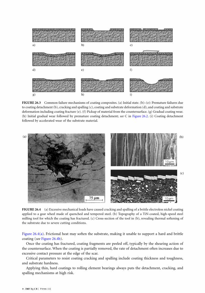
Figure 26.4(a). Frictional heat may soften the substrate, making it unable to support a hard and brittlecoating (see Figure 26.4b).
Once the coating has fractured, coating fragments are peeled off, typically by the shearing action ofthe countersurface. When the coating is partially removed, the rate of detachment often increases due toexcessive contact pressure at the edge of the scar.
Critical parameters to resist coating cracking and spalling include coating thickness and toughness,and substrate hardness.
Applying thin, hard coatings to rolling element bearings always puts the detachment, cracking, andspalling mechanisms at high risk.
FIGURE 26.3 Common failure mechanisms of coating composites. (a) Initial state. (b)–(e): Premature failures dueto coating detachment (b), cracking and spalling (c), coating and substrate deformation (d), and coating and substratedeformation including coating fracture (e). (f) Pickup of material from the countersurface. (g) Gradual coating wear.(h) Initial gradual wear followed by premature coating detachment; see C in Figure 26.2. (i) Coating detachmentfollowed by accelerated wear of the substrate material.
FIGURE 26.4 (a) Excessive mechanical loads have caused cracking and spalling of a brittle electroless nickel coatingapplied to a gear wheel made of quenched and tempered steel. (b) Topography of a TiN-coated, high-speed steelmilling tool for which the coating has fractured. (c) Cross-section of the tool in (b), revealing thermal softening ofthe substrate due to severe cutting conditions.
(a) (b)
(c)
Permanent deformation of the coating composite basically involves permanent changes in componentgeometry and/or in surface topography. Decisive parameters for a change in geometry are Young’smodulus and the hardness of coating and substrate, and coating toughness (see Section 26.4.4). Tinyscratches or cracks may disqualify a forming tool used to, for example, press compact disks. Coatinghardness is the crucial parameter for scratch resistance, and coating toughness or fracture resistance forthe resistance to surface cracking.
Work material locally adhered to, for example, the surface of a sheet forming tool used in the auto-motive industry will inevitably produce indentations or scratches in the surface of the product. Materialtransfer between the contact surfaces of sliding machine elements is a similar problem, often namedgalling, scuffing, or seizure.
Pickup of material from the countersurface is typical of many situations of sliding contact, and by nomeans unique to coating composites. It is generally reduced or avoided by giving the surface a smoothtopography and making sure that the chemical affinity to the countersurface is low. This is often accom-plished by applying a proper coating.
Tribochemical layers may form when, for example, machining certain work materials at high cuttingspeeds. They are the result of mechanical smearing of or chemical reactions with constituents in the workmaterial, and may have the positive effect of protecting the coating from excessive damage (Nordgrenand Melander, 1994; Palmai, 1984).
26.1.2.2 Failure Due to Gradual Wear
This category of failure includes regular wear; that is, gradual material loss mainly determined by theintrinsic coating properties. When thin PVD or CVD coatings are involved, gradual wear often meansmild wear due to abrasion, erosion, chemical dissolution, etc., and does not, in principle, deviate fromthe mechanisms causing wear of homogeneous materials. Suitable evaluation techniques are given inSection 26.4.5.
Because the wear rate of thin coatings in most applications is extremely low, oxidation and other typesof chemical degradations often play a significant role. In typical applications of bulk materials, the wearmechanisms are normally characterized as mechanical.
The resistance against abrasive wear of coatings increases with coating hardness, which preferablyshould be higher than that of the counter material (at the relevant contact temperature) (Khruschov,1974). High Young’s modulus and hardness of both coating and substrate, combined with a sufficientcoating thickness, are also important in avoiding cracking caused by deformation of the substrate (seeSection 26.3).
Resistance to particle erosion (i.e., wear due to mechanical attack by liquid or gas-borne particles)requires a coating that combines high hardness, fracture toughness, and corrosion resistance. The tough-ness is usually the most decisive parameter if the erosion results in a mechanically dominated materialremoval mechanism.
Adhesive wear of today’s coating materials rarely occurs unless the strength of the coating material isweakened by thermal softening and/or chemical attack from the counter material or the environment.
A high contact temperature facilitates chemical degradation and dissolution. In some instances, theselection of coating material has to be performed in consideration of the ability of the counter material(e.g., work material in a forming operation) or environment (e.g., lubricant of a machine component)to react (or not react) chemically with the coating. Sometimes, protective layers are formed by suchreactions; but more often, they promote the gradual coating wear.
26.1.3 Tribological Coatings of Today
26.1.3.1 General Overview
Application of surface coatings for tribological uses may require deposition temperatures ranging fromroom temperature up to more than 1000°C (Figure 26.5). The coating thickness ranges from microns toseveral millimeters. Typically, the atomistic methods produce the thinnest coatings. For some methods,
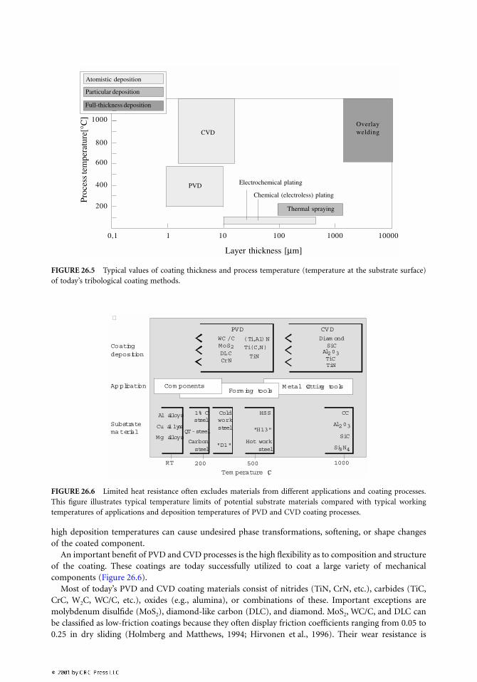
high deposition temperatures can cause undesired phase transformations, softening, or shape changesof the coated component.
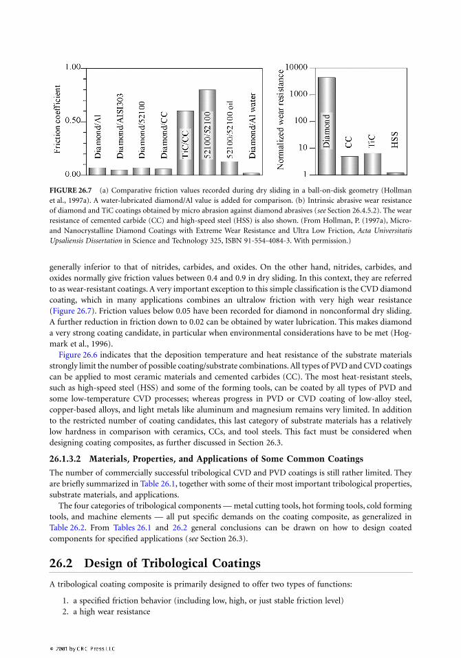
An important benefit of PVD and CVD processes is the high flexibility as to composition and structureof the coating. These coatings are today successfully utilized to coat a large variety of mechanicalcomponents (Figure 26.6).
Most of today’s PVD and CVD coating materials consist of nitrides (TiN, CrN, etc.), carbides (TiC,CrC, W2C, WC/C, etc.), oxides (e.g., alumina), or combinations of these. Important exceptions aremolybdenum disulfide (MoS2), diamond-like carbon (DLC), and diamond. MoS2, WC/C, and DLC canbe classified as low-friction coatings because they often display friction coefficients ranging from 0.05 to0.25 in dry sliding (Holmberg and Matthews, 1994; Hirvonen et al., 1996). Their wear resistance is
FIGURE 26.5 Typical values of coating thickness and process temperature (temperature at the substrate surface)of today’s tribological coating methods.
FIGURE 26.6 Limited heat resistance often excludes materials from different applications and coating processes.This figure illustrates typical temperature limits of potential substrate materials compared with typical workingtemperatures of applications and deposition temperatures of PVD and CVD coating processes.
Full-thickness deposition
Particular deposition
Atomistic deposition
PVD Electrochemical plating
Chemical (electroless) plating
Thermal spraying
Layer thickness [µm]
Proc
ess t
empe
ratu
re[°
C]
CVD
1000
800
600
400
200
0,1 1 10 100 1000 10000
Overlaywelding
�
M etal Cutting tools
CV DPVD
Diam ondSiC
Al203TiCTiN
Ti(C,N)
(Ti,Al)NWC /C MoS2
CrNDLC
Form ing toolsCom ponents
Al203
Si3N4
SiC
CCHSS
"H13"
Hot work steel
Cold worksteel
"D1"
1% Csteel
Al alloys
Mg alloysQT-steel
TiN
Cu alloys
Carbon steel
RT 200 500 1000
Tem perature ¡C
Coating deposition
Application
Substratema terial
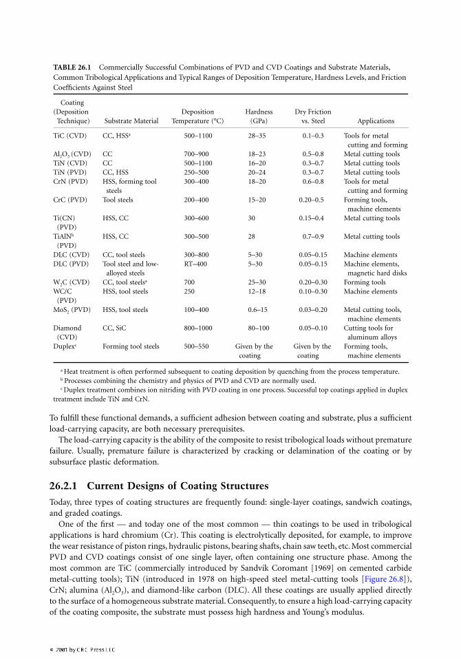
generally inferior to that of nitrides, carbides, and oxides. On the other hand, nitrides, carbides, andoxides normally give friction values between 0.4 and 0.9 in dry sliding. In this context, they are referredto as wear-resistant coatings. A very important exception to this simple classification is the CVD diamondcoating, which in many applications combines an ultralow friction with very high wear resistance(Figure 26.7). Friction values below 0.05 have been recorded for diamond in nonconformal dry sliding.A further reduction in friction down to 0.02 can be obtained by water lubrication. This makes diamonda very strong coating candidate, in particular when environmental considerations have to be met (Hog-mark et al., 1996).
Figure 26.6 indicates that the deposition temperature and heat resistance of the substrate materialsstrongly limit the number of possible coating/substrate combinations. All types of PVD and CVD coatingscan be applied to most ceramic materials and cemented carbides (CC). The most heat-resistant steels,such as high-speed steel (HSS) and some of the forming tools, can be coated by all types of PVD andsome low-temperature CVD processes; whereas progress in PVD or CVD coating of low-alloy steel,copper-based alloys, and light metals like aluminum and magnesium remains very limited. In additionto the restricted number of coating candidates, this last category of substrate materials has a relativelylow hardness in comparison with ceramics, CCs, and tool steels. This fact must be considered whendesigning coating composites, as further discussed in Section 26.3.
26.1.3.2 Materials, Properties, and Applications of Some Common Coatings
The number of commercially successful tribological CVD and PVD coatings is still rather limited. Theyare briefly summarized in Table 26.1, together with some of their most important tribological properties,substrate materials, and applications.
The four categories of tribological components — metal cutting tools, hot forming tools, cold formingtools, and machine elements — all put specific demands on the coating composite, as generalized inTable 26.2. From Tables 26.1 and 26.2 general conclusions can be drawn on how to design coatedcomponents for specified applications (see Section 26.3).
26.2 Design of Tribological Coatings
A tribological coating composite is primarily designed to offer two types of functions:
1. a specified friction behavior (including low, high, or just stable friction level)2. a high wear resistance
FIGURE 26.7 (a) Comparative friction values recorded during dry sliding in a ball-on-disk geometry (Hollmanet al., 1997a). A water-lubricated diamond/Al value is added for comparison. (b) Intrinsic abrasive wear resistanceof diamond and TiC coatings obtained by micro abrasion against diamond abrasives (see Section 26.4.5.2). The wearresistance of cemented carbide (CC) and high-speed steel (HSS) is also shown. (From Hollman, P. (1997a), Micro-and Nanocrystalline Diamond Coatings with Extreme Wear Resistance and Ultra Low Friction, Acta UniversitatisUpsaliensis Dissertation in Science and Technology 325, ISBN 91-554-4084-3. With permission.)
To fulfill these functional demands, a sufficient adhesion between coating and substrate, plus a sufficientload-carrying capacity, are both necessary prerequisites.
The load-carrying capacity is the ability of the composite to resist tribological loads without prematurefailure. Usually, premature failure is characterized by cracking or delamination of the coating or bysubsurface plastic deformation.
26.2.1 Current Designs of Coating Structures
Today, three types of coating structures are frequently found: single-layer coatings, sandwich coatings,and graded coatings.
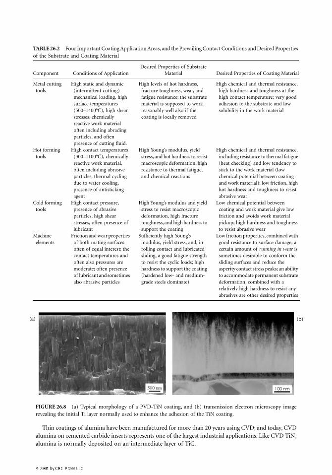
One of the first — and today one of the most common — thin coatings to be used in tribologicalapplications is hard chromium (Cr). This coating is electrolytically deposited, for example, to improvethe wear resistance of piston rings, hydraulic pistons, bearing shafts, chain saw teeth, etc. Most commercialPVD and CVD coatings consist of one single layer, often containing one structure phase. Among themost common are TiC (commercially introduced by Sandvik Coromant [1969] on cemented carbidemetal-cutting tools); TiN (introduced in 1978 on high-speed steel metal-cutting tools [Figure 26.8]),CrN; alumina (Al2O3), and diamond-like carbon (DLC). All these coatings are usually applied directlyto the surface of a homogeneous substrate material. Consequently, to ensure a high load-carrying capacityof the coating composite, the substrate must possess high hardness and Young’s modulus.
TABLE 26.1 Commercially Successful Combinations of PVD and CVD Coatings and Substrate Materials, Common Tribological Applications and Typical Ranges of Deposition Temperature, Hardness Levels, and Friction Coefficients Against Steel
Coating (Deposition
Technique) Substrate MaterialDeposition
Temperature (°C)Hardness
(GPa)Dry Friction
vs. Steel Applications
TiC (CVD) CC, HSSa 500–1100 28–35 0.1–0.3 Tools for metal cutting and forming
Al2O3 (CVD) CC 700–900 18–23 0.5–0.8 Metal cutting toolsTiN (CVD) CC 500–1100 16–20 0.3–0.7 Metal cutting toolsTiN (PVD) CC, HSS 250–500 20–24 0.3–0.7 Metal cutting toolsCrN (PVD) HSS, forming tool
steels300–400 18–20 0.6–0.8 Tools for metal
cutting and formingCrC (PVD) Tool steels 200–400 15–20 0.20–0.5 Forming tools,
machine elementsTi(CN)
(PVD)HSS, CC 300–600 30 0.15–0.4 Metal cutting tools
TiAlNb (PVD)
HSS, CC 300–500 28 0.7–0.9 Metal cutting tools
DLC (CVD) CC, tool steels 300–800 5–30 0.05–0.15 Machine elementsDLC (PVD) Tool steel and low-
alloyed steelsRT–400 5–30 0.05–0.15 Machine elements,
magnetic hard disksW2C (CVD) CC, tool steelsa 700 25–30 0.20–0.30 Forming tools WC/C
(PVD)HSS, tool steels 250 12–18 0.10–0.30 Machine elements
MoS2 (PVD) HSS, tool steels 100–400 0.6–15 0.03–0.20 Metal cutting tools, machine elements
Diamond (CVD)
CC, SiC 800–1000 80–100 0.05–0.10 Cutting tools for aluminum alloys
Duplexc Forming tool steels 500–550 Given by the coating
Given by the coating
Forming tools, machine elements
a Heat treatment is often performed subsequent to coating deposition by quenching from the process temperature.b Processes combining the chemistry and physics of PVD and CVD are normally used.c Duplex treatment combines ion nitriding with PVD coating in one process. Successful top coatings applied in duplex
treatment include TiN and CrN.
(
Thin coatings of alumina have been manufactured for more than 20 years using CVD; and today, CVDalumina on cemented carbide inserts represents one of the largest industrial applications. Like CVD TiN,alumina is normally deposited on an intermediate layer of TiC.
TABLE 26.2 Four Important Coating Application Areas, and the Prevailing Contact Conditions and Desired Properties of the Substrate and Coating Material
Component Conditions of ApplicationDesired Properties of Substrate
Material Desired Properties of Coating Material
Metal cutting tools
High static and dynamic (intermittent cutting) mechanical loading, high surface temperatures (500–1400°C), high shear stresses, chemically reactive work material often including abrading particles, and often presence of cutting fluid.
High levels of hot hardness, fracture toughness, wear, and fatigue resistance; the substrate material is supposed to work reasonably well also if the coating is locally removed
High chemical and thermal resistance, high hardness and toughness at the high contact temperature; very good adhesion to the substrate and low solubility in the work material
Hot forming tools
High contact temperatures (300–1100°C), chemically reactive work material, often including abrasive particles, thermal cycling due to water cooling, presence of antisticking agent
High Young’s modulus, yield stress, and hot hardness to resist macroscopic deformation, high resistance to thermal fatigue, and chemical reactions
High chemical and thermal resistance, including resistance to thermal fatigue (heat checking) and low tendency to stick to the work material (low chemical potential between coating and work material); low friction, high hot hardness and toughness to resist abrasive wear
Cold forming tools
High contact pressure, presence of abrasive particles, high shear stresses, often presence of lubricant
High Young’s modulus and yield stress to resist macroscopic deformation, high fracture toughness, and high hardness to support the coating
Low chemical potential between coating and work material give low friction and avoids work material pickup; high hardness and toughness to resist abrasive wear
Machine elements
Friction and wear properties of both mating surfaces often of equal interest; the contact temperatures and often also pressures are moderate; often presence of lubricant and sometimes also abrasive particles
Sufficiently high Young’s modulus, yield stress, and, in rolling contact and lubricated sliding, a good fatigue strength to resist the cyclic loads; high hardness to support the coating (hardened low- and medium-grade steels dominate)
Low friction properties, combined with good resistance to surface damage; a certain amount of running in wear is sometimes desirable to conform the sliding surfaces and reduce the asperity contact stress peaks; an ability to accommodate permanent substrate deformation, combined with a relatively high hardness to resist any abrasives are other desired properties
FIGURE 26.8 (a) Typical morphology of a PVD-TiN coating, and (b) transmission electron microscopy imagerevealing the initial Ti layer normally used to enhance the adhesion of the TiN coating.
a) (b)
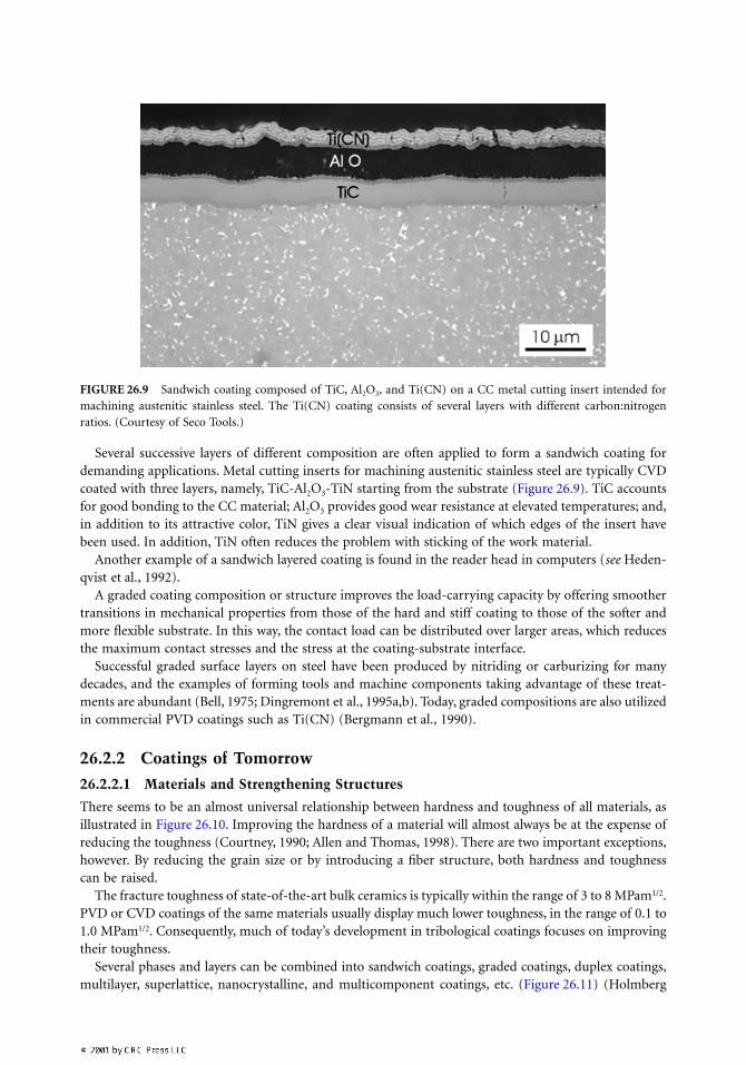
Several successive layers of different composition are often applied to form a sandwich coating fordemanding applications. Metal cutting inserts for machining austenitic stainless steel are typically CVDcoated with three layers, namely, TiC-Al2O3-TiN starting from the substrate (Figure 26.9). TiC accountsfor good bonding to the CC material; Al2O3 provides good wear resistance at elevated temperatures; and,in addition to its attractive color, TiN gives a clear visual indication of which edges of the insert havebeen used. In addition, TiN often reduces the problem with sticking of the work material.
Another example of a sandwich layered coating is found in the reader head in computers (see Heden-qvist et al., 1992).
A graded coating composition or structure improves the load-carrying capacity by offering smoothertransitions in mechanical properties from those of the hard and stiff coating to those of the softer andmore flexible substrate. In this way, the contact load can be distributed over larger areas, which reducesthe maximum contact stresses and the stress at the coating-substrate interface.
Successful graded surface layers on steel have been produced by nitriding or carburizing for manydecades, and the examples of forming tools and machine components taking advantage of these treat-ments are abundant (Bell, 1975; Dingremont et al., 1995a,b). Today, graded compositions are also utilizedin commercial PVD coatings such as Ti(CN) (Bergmann et al., 1990).
26.2.2 Coatings of Tomorrow
26.2.2.1 Materials and Strengthening Structures
There seems to be an almost universal relationship between hardness and toughness of all materials, asillustrated in Figure 26.10. Improving the hardness of a material will almost always be at the expense ofreducing the toughness (Courtney, 1990; Allen and Thomas, 1998). There are two important exceptions,however. By reducing the grain size or by introducing a fiber structure, both hardness and toughnesscan be raised.
The fracture toughness of state-of-the-art bulk ceramics is typically within the range of 3 to 8 MPam1/2.PVD or CVD coatings of the same materials usually display much lower toughness, in the range of 0.1 to1.0 MPam1/2. Consequently, much of today’s development in tribological coatings focuses on improvingtheir toughness.
Several phases and layers can be combined into sandwich coatings, graded coatings, duplex coatings,multilayer, superlattice, nanocrystalline, and multicomponent coatings, etc. (Figure 26.11) (Holmberg
FIGURE 26.9 Sandwich coating composed of TiC, Al2O3, and Ti(CN) on a CC metal cutting insert intended formachining austenitic stainless steel. The Ti(CN) coating consists of several layers with different carbon:nitrogenratios. (Courtesy of Seco Tools.)
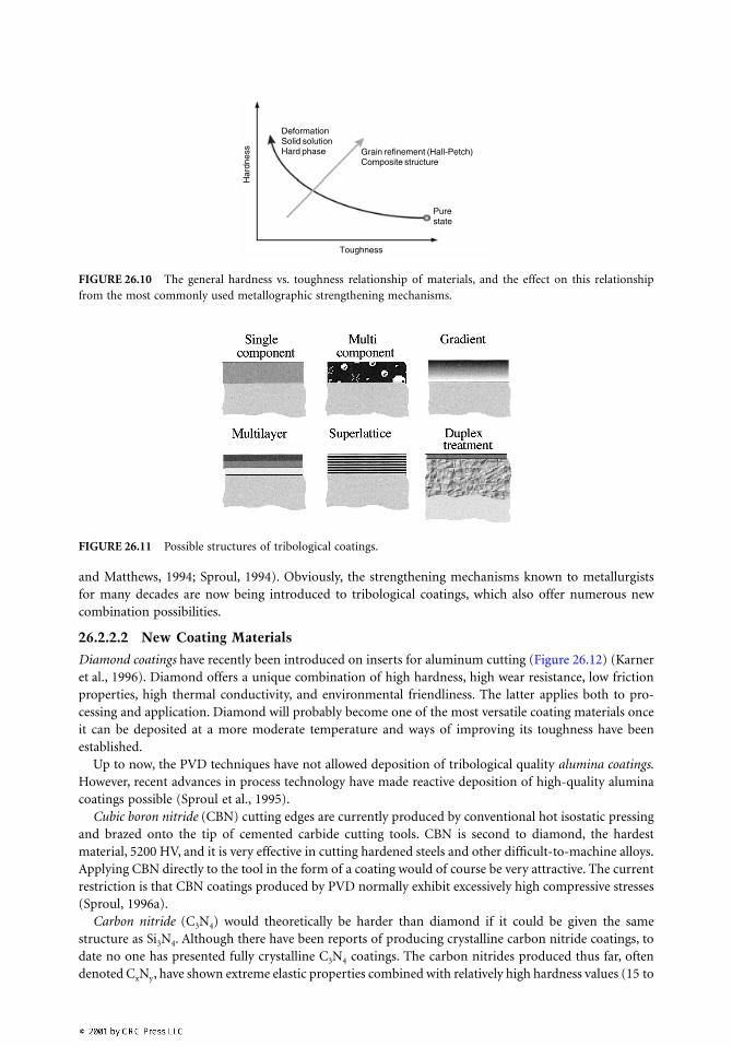
and Matthews, 1994; Sproul, 1994). Obviously, the strengthening mechanisms known to metallurgistsfor many decades are now being introduced to tribological coatings, which also offer numerous newcombination possibilities.
26.2.2.2 New Coating Materials
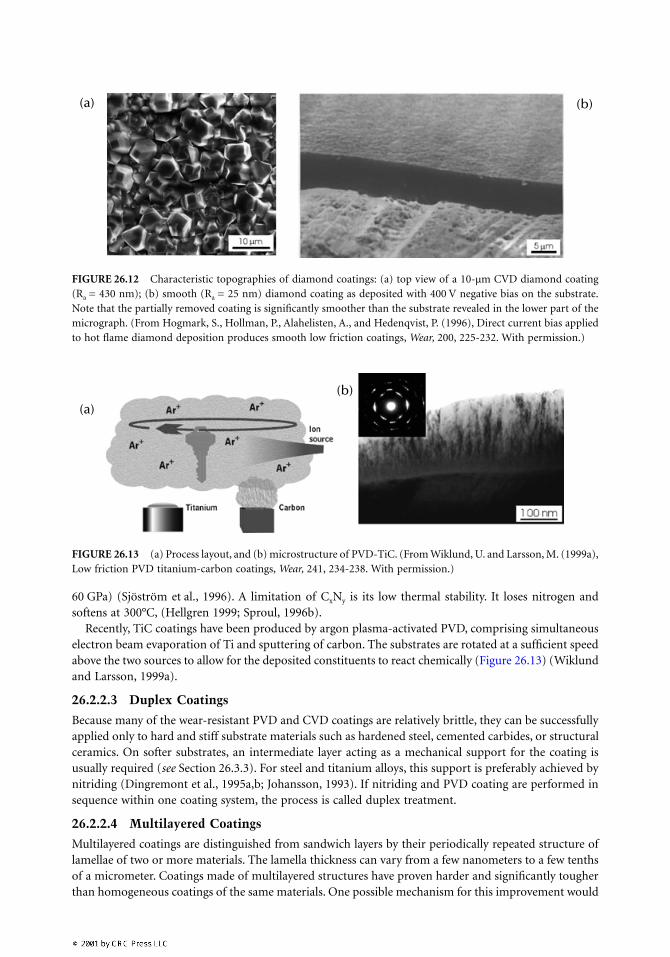
Diamond coatings have recently been introduced on inserts for aluminum cutting (Figure 26.12) (Karneret al., 1996). Diamond offers a unique combination of high hardness, high wear resistance, low frictionproperties, high thermal conductivity, and environmental friendliness. The latter applies both to pro-cessing and application. Diamond will probably become one of the most versatile coating materials onceit can be deposited at a more moderate temperature and ways of improving its toughness have beenestablished.
Up to now, the PVD techniques have not allowed deposition of tribological quality alumina coatings.However, recent advances in process technology have made reactive deposition of high-quality aluminacoatings possible (Sproul et al., 1995).
Cubic boron nitride (CBN) cutting edges are currently produced by conventional hot isostatic pressingand brazed onto the tip of cemented carbide cutting tools. CBN is second to diamond, the hardestmaterial, 5200 HV, and it is very effective in cutting hardened steels and other difficult-to-machine alloys.Applying CBN directly to the tool in the form of a coating would of course be very attractive. The currentrestriction is that CBN coatings produced by PVD normally exhibit excessively high compressive stresses(Sproul, 1996a).
Carbon nitride (C3N4) would theoretically be harder than diamond if it could be given the samestructure as Si3N4. Although there have been reports of producing crystalline carbon nitride coatings, todate no one has presented fully crystalline C3N4 coatings. The carbon nitrides produced thus far, oftendenoted CxNy, have shown extreme elastic properties combined with relatively high hardness values (15 to
FIGURE 26.10 The general hardness vs. toughness relationship of materials, and the effect on this relationshipfrom the most commonly used metallographic strengthening mechanisms.
FIGURE 26.11 Possible structures of tribological coatings.
Grain refinement (Hall-Petch)Composite structure
Purestate
ToughnessH
ardn
ess
DeformationSolid solutionHard phase
60 GPa) (Sjöström et al., 1996). A limitation of CxNy is its low thermal stability. It loses nitrogen andsoftens at 300°C, (Hellgren 1999; Sproul, 1996b).
Recently, TiC coatings have been produced by argon plasma-activated PVD, comprising simultaneouselectron beam evaporation of Ti and sputtering of carbon. The substrates are rotated at a sufficient speedabove the two sources to allow for the deposited constituents to react chemically (Figure 26.13) (Wiklundand Larsson, 1999a).
26.2.2.3 Duplex Coatings
Because many of the wear-resistant PVD and CVD coatings are relatively brittle, they can be successfullyapplied only to hard and stiff substrate materials such as hardened steel, cemented carbides, or structuralceramics. On softer substrates, an intermediate layer acting as a mechanical support for the coating isusually required (see Section 26.3.3). For steel and titanium alloys, this support is preferably achieved bynitriding (Dingremont et al., 1995a,b; Johansson, 1993). If nitriding and PVD coating are performed insequence within one coating system, the process is called duplex treatment.
26.2.2.4 Multilayered Coatings
Multilayered coatings are distinguished from sandwich layers by their periodically repeated structure oflamellae of two or more materials. The lamella thickness can vary from a few nanometers to a few tenthsof a micrometer. Coatings made of multilayered structures have proven harder and significantly tougherthan homogeneous coatings of the same materials. One possible mechanism for this improvement would
FIGURE 26.12 Characteristic topographies of diamond coatings: (a) top view of a 10-µm CVD diamond coating(Ra = 430 nm); (b) smooth (Ra = 25 nm) diamond coating as deposited with 400 V negative bias on the substrate.Note that the partially removed coating is significantly smoother than the substrate revealed in the lower part of themicrograph. (From Hogmark, S., Hollman, P., Alahelisten, A., and Hedenqvist, P. (1996), Direct current bias appliedto hot flame diamond deposition produces smooth low friction coatings, Wear, 200, 225-232. With permission.)
FIGURE 26.13 (a) Process layout, and (b) microstructure of PVD-TiC. (From Wiklund, U. and Larsson, M. (1999a),Low friction PVD titanium-carbon coatings, Wear, 241, 234-238. With permission.)
(a) (b)
(a)(b)
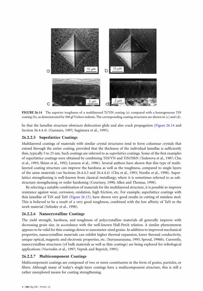
be that the lamellae structure obstructs dislocation glide and also crack propagation (Figure 26.14 andSection 26.4.4.4) (Gunnars, 1997; Sugimura et al., 1995).
26.2.2.5 Superlattice Coatings
Multilayered coatings of materials with similar crystal structures tend to form columnar crystals thatextend through the entire coating, provided that the thickness of the individual lamellae is sufficientlythin, typically 5 to 25 nm. Such coatings are referred to as superlattice coatings. Some of the first examplesof superlattice coatings were obtained by combining TiN/VN and TiN/NbN (Todorova et al., 1987; Chuet al., 1993; Shinn et al., 1992; Larsson et al., 1996). Several authors have shown that this type of multi-layered coating structure can improve the hardness as well as the toughness, compared to single layersof the same materials (see Sections 26.4.4.3 and 26.4.4.4) (Chu et al., 1993; Nordin et al., 1998). Super-lattice strengthening is well-known from classical metallurgy, where it is sometimes referred to as sub-structure strengthening or order hardening (Courtney, 1990; Allen and Thomas, 1998).
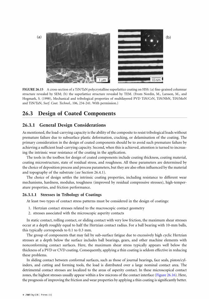
By selecting a suitable combination of materials for the multilayered structure, it is possible to improveresistance against wear, corrosion, oxidation, high friction, etc. For example, superlattice coatings withthin lamellae of TiN and TaN (Figure 26.15), have shown very good results in cutting of stainless steel.This is believed to be a result of a very good toughness, combined with the low affinity of TaN to thework material (Selinder et al., 1998).
26.2.2.6 Nanocrystalline Coatings
The yield strength, hardness, and toughness of polycrystalline materials all generally improve withdecreasing grain size, in accordance with the well-known Hall-Petch relation. A similar phenomenonappears to be valid for thin coatings down to nanometer-sized grains. In addition to improved mechanicalproperties, nanocrystalline materials can exhibit higher thermal expansion, lower thermal conductivity,unique optical, magnetic and electronic properties, etc. (Suryanarayana, 1995; Sproul, 1996b). Currently,nanocrystalline structures (of bulk materials as well as thin coatings) are being explored for tribologicalapplications (Voevodin et al., 1997; Veprek and Reprich, 1995).
26.2.2.7 Multicomponent Coatings
Multicomponent coatings are composed of two or more constituents in the form of grains, particles, orfibers. Although many of today’s single-layer coatings have a multicomponent structure, this is still arather unexplored means for coating strengthening.
FIGURE 26.14 The superior toughness of a multilayered Ti/TiN coating (a) compared with a homogeneous TiNcoating (b), as demonstrated by 500 gf Vickers indents. The corresponding coating structures are shown in (c) and (d).
26.3 Design of Coated Components
26.3.1 General Design Considerations
As mentioned, the load-carrying capacity is the ability of the composite to resist tribological loads withoutpremature failure due to subsurface plastic deformation, cracking, or delamination of the coating. Theprimary consideration in the design of coated components should be to avoid such premature failure byachieving a sufficient load-carrying capacity. Second, when this is achieved, attention is turned to increas-ing the intrinsic wear resistance of the coating in the application.
The tools in the toolbox for design of coated components include coating thickness, coating material,coating microstructure, state of residual stress, and roughness. All these parameters are determined bythe choice of deposition process and process parameters, but they are also often influenced by the materialand topography of the substrate (see Section 26.4.1).
The choice of design settles the intrinsic coating properties, including resistance to different wearmechanisms, hardness, modulus, toughness (improved by residual compressive stresses), high-temper-ature properties, and friction performance.
26.3.1.1 Stresses in Tribology of Coatings
At least two types of contact stress patterns must be considered in the design of coatings:
1. Hertzian contact stresses related to the macroscopic contact geometry2. stresses associated with the microscopic asperity contacts
In static contact, rolling contact, or sliding contact with very low friction, the maximum shear stressesoccur at a depth roughly equal to half the Hertzian contact radius. For a ball bearing with 10-mm balls,this typically corresponds to 0.1 to 0.3 mm.
The group of components that may fail by sub-surface fatigue due to excessively high cyclic Hertzianstresses at a depth below the surface includes ball bearings, gears, and other machine elements withnonconforming contact surfaces. Here, the maximum shear stress typically appears well below thethickness of a PVD or CVD coating. Consequently, applying a thin coating is seldom effective in reducingthese problems.
In sliding contact between conformal surfaces, such as those of journal bearings, face seals, piston/cyl-inders, and cutting and forming tools, the load is distributed over a large nominal contact area. Thedetrimental contact stresses are localized to the areas of asperity contact. In these microscopical contactzones, the highest stresses usually appear within a few microns of the contact interface (Figure 26.16). Here,the prognosis of improving the friction and wear properties by applying a thin coating is significantly better.
FIGURE 26.15 A cross-section of a TiN/TaN polycrystalline superlattice coating on HSS: (a) fine-grained columnarstructure revealed by SEM; (b) the superlattice structure revealed by TEM. (From Nordin, M., Larsson, M., andHogmark, S. (1998), Mechanical and tribological properties of multilayered PVD TiN/CrN, TiN/NbN, TiN/MoNand TiN/TaN, Surf. Coat. Technol., 106, 234-241. With permission.)
(a) (b)
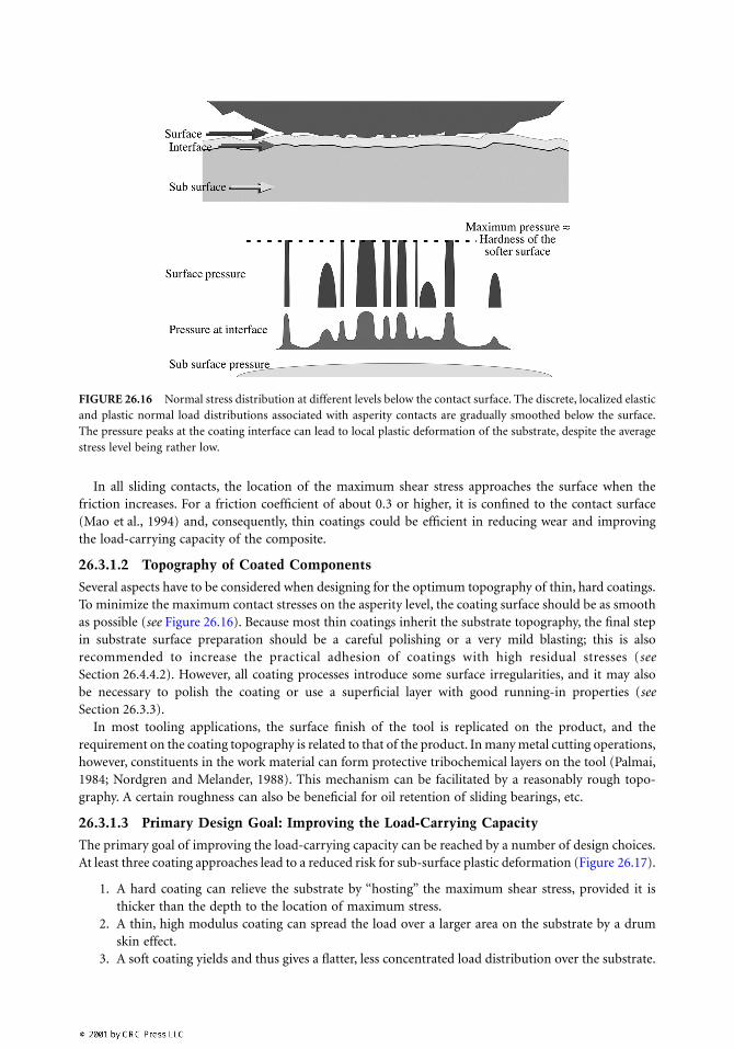
In all sliding contacts, the location of the maximum shear stress approaches the surface when thefriction increases. For a friction coefficient of about 0.3 or higher, it is confined to the contact surface(Mao et al., 1994) and, consequently, thin coatings could be efficient in reducing wear and improvingthe load-carrying capacity of the composite.
26.3.1.2 Topography of Coated Components
Several aspects have to be considered when designing for the optimum topography of thin, hard coatings.To minimize the maximum contact stresses on the asperity level, the coating surface should be as smoothas possible (see Figure 26.16). Because most thin coatings inherit the substrate topography, the final stepin substrate surface preparation should be a careful polishing or a very mild blasting; this is alsorecommended to increase the practical adhesion of coatings with high residual stresses (seeSection 26.4.4.2). However, all coating processes introduce some surface irregularities, and it may alsobe necessary to polish the coating or use a superficial layer with good running-in properties (seeSection 26.3.3).
In most tooling applications, the surface finish of the tool is replicated on the product, and therequirement on the coating topography is related to that of the product. In many metal cutting operations,however, constituents in the work material can form protective tribochemical layers on the tool (Palmai,1984; Nordgren and Melander, 1988). This mechanism can be facilitated by a reasonably rough topo-graphy. A certain roughness can also be beneficial for oil retention of sliding bearings, etc.
26.3.1.3 Primary Design Goal: Improving the Load-Carrying Capacity
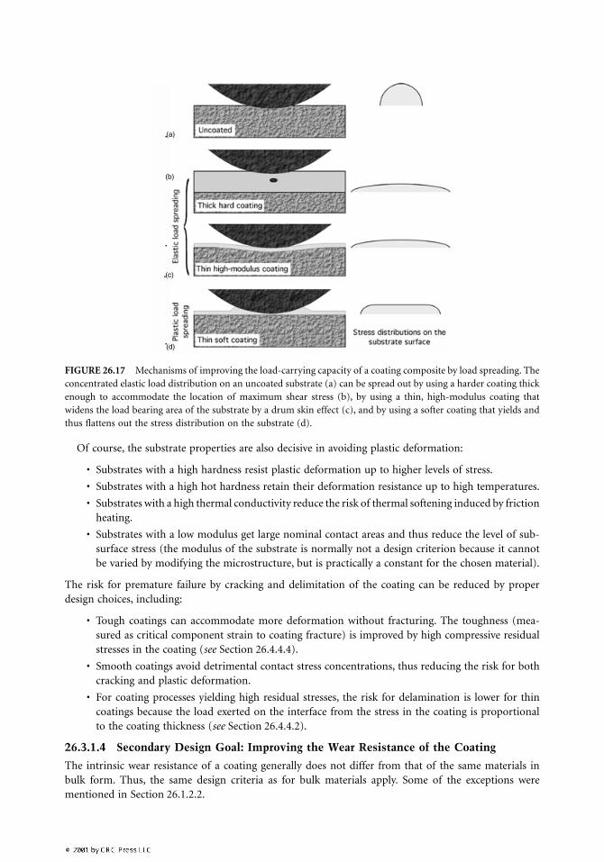
The primary goal of improving the load-carrying capacity can be reached by a number of design choices.At least three coating approaches lead to a reduced risk for sub-surface plastic deformation (Figure 26.17).
1. A hard coating can relieve the substrate by “hosting” the maximum shear stress, provided it isthicker than the depth to the location of maximum stress.
2. A thin, high modulus coating can spread the load over a larger area on the substrate by a drumskin effect.
3. A soft coating yields and thus gives a flatter, less concentrated load distribution over the substrate.
FIGURE 26.16 Normal stress distribution at different levels below the contact surface. The discrete, localized elasticand plastic normal load distributions associated with asperity contacts are gradually smoothed below the surface.The pressure peaks at the coating interface can lead to local plastic deformation of the substrate, despite the averagestress level being rather low.
Of course, the substrate properties are also decisive in avoiding plastic deformation:
• Substrates with a high hardness resist plastic deformation up to higher levels of stress.
• Substrates with a high hot hardness retain their deformation resistance up to high temperatures.
• Substrates with a high thermal conductivity reduce the risk of thermal softening induced by frictionheating.
• Substrates with a low modulus get large nominal contact areas and thus reduce the level of sub-surface stress (the modulus of the substrate is normally not a design criterion because it cannotbe varied by modifying the microstructure, but is practically a constant for the chosen material).
The risk for premature failure by cracking and delimitation of the coating can be reduced by properdesign choices, including:
• Tough coatings can accommodate more deformation without fracturing. The toughness (mea-sured as critical component strain to coating fracture) is improved by high compressive residualstresses in the coating (see Section 26.4.4.4).
• Smooth coatings avoid detrimental contact stress concentrations, thus reducing the risk for bothcracking and plastic deformation.
• For coating processes yielding high residual stresses, the risk for delamination is lower for thincoatings because the load exerted on the interface from the stress in the coating is proportionalto the coating thickness (see Section 26.4.4.2).
26.3.1.4 Secondary Design Goal: Improving the Wear Resistance of the Coating
The intrinsic wear resistance of a coating generally does not differ from that of the same materials inbulk form. Thus, the same design criteria as for bulk materials apply. Some of the exceptions werementioned in Section 26.1.2.2.
FIGURE 26.17 Mechanisms of improving the load-carrying capacity of a coating composite by load spreading. Theconcentrated elastic load distribution on an uncoated substrate (a) can be spread out by using a harder coating thickenough to accommodate the location of maximum shear stress (b), by using a thin, high-modulus coating thatwidens the load bearing area of the substrate by a drum skin effect (c), and by using a softer coating that yields andthus flattens out the stress distribution on the substrate (d).
(b)
(a)
(c)
(d)
26.3.2 Design Considerations for Cutting Tools
Cutting tools will probably continue to be a leading application of modern tribological coatings. Theyare relatively small so that batch coating can keep the cost within reasonable limits, even for high-techcoatings of, for example, nanocrystalline and nanolayered multicomponent layers.
Today, there are two obvious trends in cutting tool developments. Dry machining is desirable to avoidthe extra costs and environmental problems associated with cutting fluids. High-speed machining ofhardened steel has the potential of giving sufficiently high quality of the machined surface to makefinishing operations such as grinding or polishing unnecessary. In both cases, the heat generation alongthe tool surfaces will be even more intense than with today’s contact conditions and, consequently, thetools must possess further improved hot hardness, thermal and chemical stability, etc.
26.3.3 Design Considerations for Forming Tools and Machine Components
Forming tools and machine components constitute much larger industrial sectors than do cutting tools,and application of thin tribological coatings on forming tools and machine components thus has enor-mous potential. There are several reasons why the use of coatings in these applications remains relativelyscarce. Many forming tools and machine elements are too large to be economically coated by today’sprocesses. Further, the substrate materials of most forming tools and machine elements cannot resist thecurrently used deposition temperatures. In addition, these components often have complicated andnarrow sections that are difficult — or even impossible — to coat. Finally, the high tool cost often makesthe user restrictive against applying new, unexplored coatings.
The automotive industry encourages research on new concepts of surface engineering, with the generalaim to substitute traditional steel components with components made of lighter materials, typicallyaluminum, titanium, and magnesium alloys. The ultimate aim is to reduce fuel consumption.
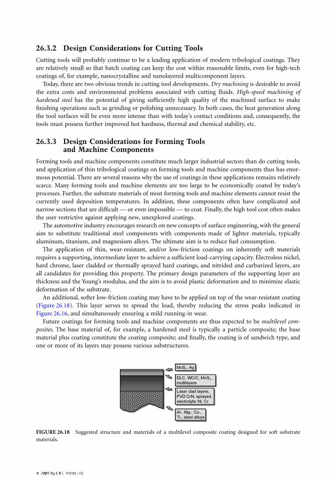
The application of thin, wear-resistant, and/or low-friction coatings on inherently soft materialsrequires a supporting, intermediate layer to achieve a sufficient load-carrying capacity. Electroless nickel,hard chrome, laser cladded or thermally sprayed hard coatings, and nitrided and carburized layers, areall candidates for providing this property. The primary design parameters of the supporting layer arethickness and the Young’s modulus, and the aim is to avoid plastic deformation and to minimize elasticdeformation of the substrate.
An additional, softer low-friction coating may have to be applied on top of the wear-resistant coating(Figure 26.18). This layer serves to spread the load, thereby reducing the stress peaks indicated inFigure 26.16, and simultaneously ensuring a mild running-in wear.
Future coatings for forming tools and machine components are thus expected to be multilevel com-posites. The base material of, for example, a hardened steel is typically a particle composite; the basematerial plus coating constitute the coating composite; and finally, the coating is of sandwich type, andone or more of its layers may possess various substructures.
FIGURE 26.18 Suggested structure and materials of a multilevel composite coating designed for soft substratematerials.
Currently, plasma-assisted PVD processes are being evaluated for production of duplex coatings (seeSection 26.2.2.3). The functional PVD coating is typically CrN or TiN or a wear-resistant, low-frictioncoating (e.g., DLC or WC/C) (Farges et al., 1989; Bell, 1997).
26.4 Evaluation of Coating Composites
26.4.1 Important Parameters
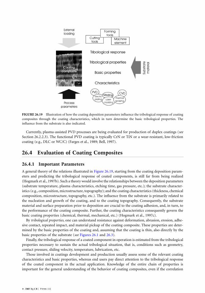
A general theory of the relations illustrated in Figure 26.19, starting from the coating deposition param-eters and predicting the tribological response of coated components, is still far from being realized(Hogmark et al., 1997b). Such a theory would involve the relationships between the deposition parameters(substrate temperature, plasma characteristics, etching time, gas pressure, etc.); the substrate character-istics (e.g., composition, microstructure, topography); and the coating characteristics (thickness, chemicalcomposition, microstructure, topography, etc.). The influence from the substrate is primarily related tothe nucleation and growth of the coating, and to the coating topography. Consequently, the substratematerial and surface preparation prior to deposition are crucial to the coating adhesion, and, in turn, tothe performance of the coating composite. Further, the coating characteristics consequently govern thebasic coating properties (chemical, thermal, mechanical, etc.) (Hogmark et al., 1997c).
By tribological properties, one can understand resistance against deformation, abrasion, erosion, adhe-sive contact, repeated impact, and material pickup of the coating composite. These properties are deter-mined by the basic properties of the coating and, assuming that the coating is thin, also directly by thebasic properties of the substrate (see Figures 26.1 and 26.3).
Finally, the tribological response of a coated component in operation is estimated from the tribologicalproperties necessary to sustain the actual tribological situation, that is, conditions such as geometry,contact pressure, sliding velocity, temperature, lubrication, etc.
Those involved in coatings development and production usually assess some of the relevant coatingcharacteristics and basic properties, whereas end users pay direct attention to the tribological responseof the coated component in the actual application. Knowledge of the entire chain of properties isimportant for the general understanding of the behavior of coating composites, even if the correlation
FIGURE 26.19 Illustration of how the coating deposition parameters influence the tribological response of coatingcomposites through the coating characteristics, which in turn determine the basic tribological properties. Theinfluence from the substrate is also indicated.
illustrated by the arrows in Figure 26.19 can only be given qualitatively. Because different applicationsput different demands on the coating composites, the set of most decisive parameters will vary.
26.4.2 Adhesion to the Substrate
Obviously, a good adhesion of the coating to the substrate is a crucial property of most applications ofcoated components. However, any adhesion test will, inevitably, superimpose a stress field over thecoating-substrate interface. This stress field will depend on the type of tribological loading (indentation,scratching, sliding, abrasion, impact, etc.), as well as on the elastic and plastic parameters of the coatingand substrate. Important parameters include the nature, magnitude, and homogeneity of coating residualstresses, the shape, flatness, and roughness of the interface, etc. Thus, any test value of adhesion will onlybe representative of the particular test from which it has been obtained.
Because the situation in the test most likely deviates significantly from that of the intended application,the result must be handled with caution. In fact, the relationships between the above parameters are socomplicated that a general theory to predict practical adhesion does not exist. One has to be very carefulwhen trying to correlate results from indentation or scratching performed with, for example, sphericaldiamond tips with the situation of sliding contact in actual components like tools and machine elements.On the other hand, scratch tests can be very useful for obtaining qualitative measures of the mechanicalstrength (adhesion, cohesion, toughness, etc.) of coating composites (see Section 26.4.5.1).
To evaluate the practical adhesion of coated components, the advice is to use, if not field tests,tribological tests with the closest possible resemblance to the actual situation.
26.4.3 Basic Coating Properties
Basic coating properties such as thickness, composition, structure, morphology, and topography are beststudied by modern imaging and analytical techniques (see Table 26.3) (Hogmark et al., 1997b).
Coating thickness and morphology of thin PVD or CVD coatings are often easy to reveal from fracturedcross-sections (see Figures 26.8, 26.12, and 26.14).
Compositional depth profiles of coatings 1 µm in thickness or less can be obtained by XPS or AES.These techniques combine alternating ion etching and analysis. Due to a larger information depth, EDSgives the average coating composition, and often also signals from the substrate material. Thicker coatingscan be profiled without prior sample preparation by GDOES (Figure 26.20). Alternatively, EDS or AEScan give the corresponding information by analyzing polished cross-sections or tapered sections.
26.4.4 Intrinsic Mechanical Properties
Some of the intrinsic mechanical properties are of particular interest. These are the Young’s modulusand residual stress, that is, properties related to elastic deformation, hardness (i.e., property related toplastic deformation), and toughness or fracture resistance (i.e., properties related to fracture).
26.4.4.1 Young’s Modulus
The intrinsic Young’s modulus (elastic modulus) of the coating (Ec) is a useful parameter in the measure-ments and calculations of the stress state and the cracking and delamination behavior of coating compos-ites. It is possible to obtain Ec through a number of techniques, but the uniaxial tensile test is the moststraightforward (Hollman et al., 1997b). The Young’s modulus of a coating can be obtained from
(26.1)
where k is the slope of the tensile curve, kg is the slope of force vs. strain for a strain gage glued to thecoated sample (determined separately), Es is the Young’s modulus of the substrate material (known), wis the width of the coated sample, and tc and ts are the thicknesses of coating and substrate, respectively.
E k E t w k t wc s s g c= − −( )
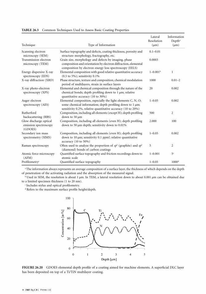
TABLE 26.3 Common Techniques Used to Assess Basic Coating Properties
Technique Type of Information
Lateral Resolution
Information Deptha
(µm) (µm)
Scanning electron microscopy (SEM)
Surface topography and defects, coating thickness, porosity and structure morphology, fractography, etc.
0.1–0.01
Transmission electron microscopy (TEM)
Grain size, morphology and defects by imaging, phase composition and orientation by electron diffraction, elemental composition by electron energy loss spectroscopy (EELS)
0.0003
Energy dispersive X-ray spectroscopy (EDS)
Elemental composition with good relative quantitative accuracy (0.5 to 5%); sensitivity 0.1%
1–0.001b 1
X-ray diffraction (XRD) Phase structure, texture and composition, chemical modulation period of multilayers, strain in surface layers
1000 0.01–2
X-ray photo-electron spectroscopy (XPS)
Elemental and chemical composition through the nature of the chemical bonds; depth profiling down to 1 µm; relative quantitative accuracy (10 to 30%)
20 0.002
Auger electron spectroscopy (AES)
Elemental composition, especially the light elements C, N, O; some chemical information; depth profiling down to 1 µm; sensitivity 0.2%, relative quantitative accuracy (10 to 20%)
1–0.05 0.002
Rutherford backscattering (RBS)
Composition, including all elements (except H); depth profiling down to 50 µm
500 2
Glow discharge optical emission spectroscopy (GDOES)
Composition, including all elements (even H); depth profiling down to 50 µm depth; sensitivity down to 0.01%
2.000 100
Secondary ion mass spectrometry (SIMS)
Composition, including all elements (even H); depth profiling down to 10 µm; sensitivity 0.1 ppm!; relative quantitative accuracy (10 to 50%)
1–0.05 0.002
Raman spectroscopy Often used to analyze the proportion of sp2 (graphite) and sp3 (diamond) bonds of carbon coatings
5 2
Atomic force microscopy (AFM)
Quantified surface topography and friction recordings down to atomic scale
1–0.001 5c
Profilometryc Quantified surface topography 1–0.05 1000d
a The information always represents an average composition of a surface layer, the thickness of which depends on the depthof penetration of the activating radiation and the absorption of the measured signal.
b Used in SEM, the resolution is about 1 µm. In TEM, a lateral resolution down to about 0.001 µm can be obtained dueto a limited specimen thickness (1 to 20 nm).
c Includes stylus and optical profilometry.d Refers to the maximum surface profile height/depth.
FIGURE 26.20 GDOES elemental depth profile of a coating aimed for machine elements. A superficial DLC layerhas been deposited on top of a Ti/TiN multilayer coating.
The intrinsic elastic modulus of thin coatings can also be determined by nanoindentation (seeSection 26.4.4.3), vibrating reed tests, bulge tests, beam bending tests, ultrasonic wave propagation, etc.(Brown et al., 1993; Rouzaud et al., 1995; Blakely, 1964; Hoffman, 1989; Schultrich et al., 1984).
26.4.4.2 Residual Stresses
Residual stresses (σres) are usually generated in PVD and CVD coatings during deposition and subsequentcooling from the deposition temperature. During deposition, structural misfits in epitactic coatingnucleation and growth, and simultaneous ion bombardment, can generate stresses of tensile or compres-sive nature. On top of these, stresses due to mismatch in thermal contraction between coating andsubstrate materials, and possible phase transformations during cooling, are superimposed (Nix, 1989).
The actual stress during application (σ) is given by:
(26.2)
where σapp denotes any stress field induced by external forces during application, including the conse-quence of frictional heating and thermal mismatch.
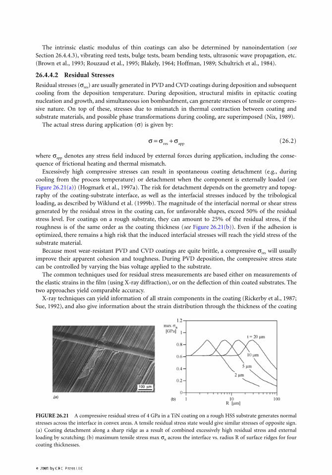
Excessively high compressive stresses can result in spontaneous coating detachment (e.g., duringcooling from the process temperature) or detachment when the component is externally loaded (seeFigure 26.21(a)) (Hogmark et al., 1997a). The risk for detachment depends on the geometry and topog-raphy of the coating-substrate interface, as well as the interfacial stresses induced by the tribologicalloading, as described by Wiklund et al. (1999b). The magnitude of the interfacial normal or shear stressgenerated by the residual stress in the coating can, for unfavorable shapes, exceed 50% of the residualstress level. For coatings on a rough substrate, they can amount to 25% of the residual stress, if theroughness is of the same order as the coating thickness (see Figure 26.21(b)). Even if the adhesion isoptimized, there remains a high risk that the induced interfacial stresses will reach the yield stress of thesubstrate material.
Because most wear-resistant PVD and CVD coatings are quite brittle, a compressive σres will usuallyimprove their apparent cohesion and toughness. During PVD deposition, the compressive stress statecan be controlled by varying the bias voltage applied to the substrate.
The common techniques used for residual stress measurements are based either on measurements ofthe elastic strains in the film (using X-ray diffraction), or on the deflection of thin coated substrates. Thetwo approaches yield comparable accuracy.
X-ray techniques can yield information of all strain components in the coating (Rickerby et al., 1987;Sue, 1992), and also give information about the strain distribution through the thickness of the coating
FIGURE 26.21 A compressive residual stress of 4 GPa in a TiN coating on a rough HSS substrate generates normalstresses across the interface in convex areas. A tensile residual stress state would give similar stresses of opposite sign.(a) Coating detachment along a sharp ridge as a result of combined excessively high residual stress and externalloading by scratching; (b) maximum tensile stress max σn across the interface vs. radius R of surface ridges for fourcoating thicknesses.
σ σ σ= +res app
(a) (b)
(Venkatraman et al., 1992). To obtain the residual stress using X-rays, the elastic constants of the coatingmust be known.
The substrate deflection techniques determine the coating residual stress by measuring the curvatureof the thin coating composite, caused by the stressed coating (Townsend and Barnett, 1987; Röll, 1976;Stoney, 1909). The deflection is often measured using laser scanning techniques or profilometry (Nix,1989). Coating to substrate thickness ratios in the range of 1:100 to 1:1000 are required for best accuracy,which means that substantial thinning is often necessary prior to deflection measurement of actualcomponents. Deflection techniques can also be used in situ during coating deposition, if sufficiently thinsubstrates are used.
Usually, the residual stress is obtained by the “thin-film approximation” technique (the coating is muchthinner than the substrate). This technique has the advantage of not requiring data of the elastic propertiesof the coating material to calculate the residual stress. This is done by applying the so-called Stoneyequation (Stoney, 1909):
(26.3)
where Es /(1 – νs) is the biaxial modulus of the substrate; ts and tc are the substrate and coating thickness,respectively; ra is the radius of curvature after coating deposition on an originally flat substrate; and rb
is the radius of curvature for the substrate prior to coating.The deflection technique assumes that the residual stresses are homogeneously distributed throughout
the coating. The accuracy of the X-ray and deflection techniques is comparable. The nature of the residualstress of PVD coatings is generally compressive due to the ion bombardment during deposition. Thenature and magnitude of the residual stresses in CVD coatings are primarily a result of the difference inthermal contraction between coating and substrate material.
26.4.4.3 Hardness
To assess coating quality and to predict the coating performance in various applications, coating devel-opers often use hardness measurements. However, the importance of a high intrinsic coating hardnessshould not be exaggerated. It is only in pure two-body abrasive wear that the wear resistance is veryclosely coupled to hardness. This also requires that the abrasives or abrasive surface is harder than thewearing surface. Almost all abrasive materials — except for coated components — are softer than 20 GPa,a value that is exceeded by many of today’s PVD and CVD coatings (see Table 26.1). When the hardnessof the coating exceeds that of the wearing, surface properties such as toughness, chemical stability, andfatigue resistance become more important.
The intrinsic hardness of thin coatings can be directly measured by conventional microhardness testingif the indentation depth does not exceed 10% of the coating thickness. Consequently, conventional Vickersindentation is restricted to coatings thicker than about 5 µm. It is possible to use microhardness valuesobtained from thinner coatings if models that take the substrate deformation into account are applied(Jönsson and Hogmark, 1984; Vingsbo et al., 1986; Burnett and Rickerby, 1987).
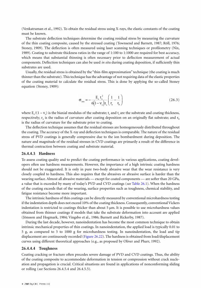
During the last decade, however, nanoindentation has become the most common technique to obtainintrinsic mechanical properties of thin coatings. In nanoindentation, the applied load is typically 0.01 to5 g, as compared to 5 to 1000 g for microhardness testing. In nanoindentation, the load and tipdisplacement are continuously recorded (Figure 26.22). The hardness is obtained from load/displacementcurves using different theoretical approaches (e.g., as proposed by Oliver and Pharr, 1992).
26.4.4.4 Toughness
Coating cracking or fracture often precedes severe damage of PVD and CVD coatings. Thus, the abilityof the coating composite to accommodate deformation in tension or compression without crack nucle-ation and propagation is crucial. Critical situations are found in applications of nonconforming slidingor rolling (see Sections 26.4.5.4 and 26.4.5.5).
σνres
s s
s c a b
E t
t r r= −
−( ) −
2
6 1
1 1
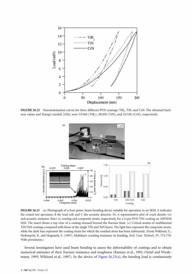
Several investigators have used beam bending to assess the deformability of coatings and to obtainnumerical estimates of their fracture resistance and toughness (Ramsey et al., 1991; Oettel and Wiede-mann, 1995; Wiklund et al., 1997). In the device of Figure 26.23(a), the bending load is continuously
FIGURE 26.22 Nanoindentation curves for three different PVD coatings: TiB2, TiN, and CrN. The obtained hard-ness values and Young’s moduli [GPa] were 53/566 (TiB2), 30/450 (TiN), and 25/330 (CrN), respectively.
FIGURE 26.23 (a) Photograph of a four-point, beam-bending device suitable for operation in an SEM. A indicatesthe coated test specimen, B the load cell, and C the acoustic detector. (b) A representative plot of crack density (o)and acoustic emission (line) vs. coating and composite strain, respectively, for a 4-µm PVD TiN-coating on ASP2030HSS. The insert shows a top view of a coating stressed beyond the fracture limit. (c) Critical strains of multilayeredTiN/TaN coatings compared with those of the single TiN and TaN layers. The light bars represent the composite strain,while the dark bars represent the coating strain for which the residual stress has been subtracted. (From Wiklund, U.,Hedenqvist, P., and Hogmark, S. (1997), Multilayer cracking resistance in bending, Surf. Coat. Technol., 97, 773-778.With permission.)
(a)
(b)
(c)
increased and the critical strain to initiation of the first crack can be recorded acoustically or in situ inthe SEM (see Figure 26.23(b)).
Multilayered coatings generally exhibit a higher critical strain to fracture than do homogeneouscoatings (see Figure 26.23(c)). Because cracking is initiated by tensile stresses, any compressive residualstress must be overcome before cracking will commence. Consequently, high compressive residual stressesin the coating increase the critical strain of the component to coating fracture. The critical compositestrain is thus a more important parameter than the critical intrinsic tensile strain of the coating.
Note also that the true fracture strain of the coating materials is very low compared to that ofhomogeneous bulk ceramics, which usually is around 1%. This indicates a great potential of improvingthe coating toughness once the weak columnar structure can be avoided.
26.4.5 Tribological PropertiesTribological properties here refer to the general tribological properties of the coating composite, for thincoatings involving influence from both coating and substrate. With relevant information on the generalfriction and wear properties, and supporting knowledge of basic coating and substrate properties, it ispossible to recommend applications for given coating composites. As discussed in Section 26.4.6, the enduser may, however, not be satisfied until a confirming field test has been performed.
Below, five tribological properties are identified and simple tests for their assessment are demonstrated.
26.4.5.1 Scratch Resistance
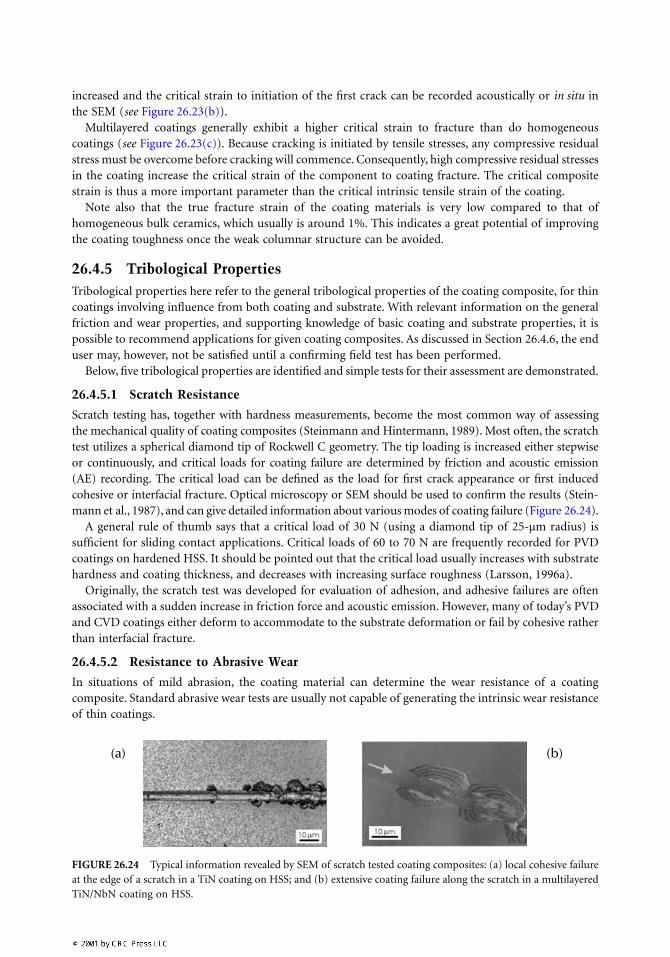
Scratch testing has, together with hardness measurements, become the most common way of assessingthe mechanical quality of coating composites (Steinmann and Hintermann, 1989). Most often, the scratchtest utilizes a spherical diamond tip of Rockwell C geometry. The tip loading is increased either stepwiseor continuously, and critical loads for coating failure are determined by friction and acoustic emission(AE) recording. The critical load can be defined as the load for first crack appearance or first inducedcohesive or interfacial fracture. Optical microscopy or SEM should be used to confirm the results (Stein-mann et al., 1987), and can give detailed information about various modes of coating failure (Figure 26.24).
A general rule of thumb says that a critical load of 30 N (using a diamond tip of 25-µm radius) issufficient for sliding contact applications. Critical loads of 60 to 70 N are frequently recorded for PVDcoatings on hardened HSS. It should be pointed out that the critical load usually increases with substratehardness and coating thickness, and decreases with increasing surface roughness (Larsson, 1996a).
Originally, the scratch test was developed for evaluation of adhesion, and adhesive failures are oftenassociated with a sudden increase in friction force and acoustic emission. However, many of today’s PVDand CVD coatings either deform to accommodate to the substrate deformation or fail by cohesive ratherthan interfacial fracture.
26.4.5.2 Resistance to Abrasive Wear
In situations of mild abrasion, the coating material can determine the wear resistance of a coatingcomposite. Standard abrasive wear tests are usually not capable of generating the intrinsic wear resistanceof thin coatings.
FIGURE 26.24 Typical information revealed by SEM of scratch tested coating composites: (a) local cohesive failureat the edge of a scratch in a TiN coating on HSS; and (b) extensive coating failure along the scratch in a multilayeredTiN/NbN coating on HSS.
(a) (b)
However, thin coatings can be evaluated in the micro-abrasion test originally proposed by Kassmanet al. (1991) and further developed by Rutherford and Hutchings (1996, 1997), and Gåhlin et al. (1997).This technique makes it possible to distinguish the abrasive wear resistance of a thin coating materialfrom that of the substrate, and also in situations where the coating is worn through.
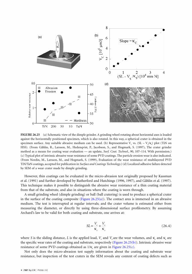
A small grinding wheel (dimple grinding) or ball (ball cratering) is used to produce a spherical craterin the surface of the coating composite (Figure 26.25(a)). The contact area is immersed in an abrasivemedium. The test is interrupted at regular intervals; and the crater volume is estimated either frommeasuring the diameter, or directly by using three-dimensional surface profilometry. By assumingArchard’s law to be valid for both coating and substrate, one arrives at:
(26.4)
where S is the sliding distance, L is the applied load, Vc and Vs are the wear volumes, and κc and κs arethe specific wear rates of the coating and substrate, respectively (Figure 26.25(b)). Intrinsic abrasive wearresistance of some PVD coatings obtained as 1/κc are given in Figure 26.25(c).
Not only does the micro-abrasion test supply information about the coating and substrate wearresistance, but inspection of the test craters in the SEM reveals any content of coating defects such as
FIGURE 26.25 (a) Schematic view of the dimple grinder. A grinding wheel rotating about horizontal axes is loadedagainst the horizontally positioned specimen, which is also rotated. In this way, a spherical crater is obtained in thespecimen surface. Any suitable abrasive medium can be used. (b) Representative Vc vs. (SL – Vs/κs) plot (TiN onHSS). (From Gåhlin, R., Larsson, M., Hedenqvist, P., Jacobson, S., and Hogmark, S. (1997), The crater grindermethod as a means for coating wear evaluation — an update, Surf. Coat. Technol., 90, 107–114. With permission.)(c) Typical plot of intrinsic abrasive wear resistance of some PVD coatings. The particle erosion wear is also indicated.(From Nordin, M., Larsson, M., and Hogmark, S. (1999), Evaluation of the wear resistance of multilayered PVDTiN/TaN coatings, accepted for publication in Surface and Coatings Technology.) (d) Localized adhesive failure detectedby SEM of a wear crater made by dimple grinding.
SLV Vc
c
s
s
= +κ κ
pores and cracks. A poor adhesion can be detected by the presence of spallings in the coating substrateinterface (see Figure 26.25(d)).
Micro-abrasion test results must be handled with caution. Two-body abrasive wear of the coated surfacedominates if the abrasives stick to the surface of the grinding wheel or ball. This is likely to be the caseif the wheel or ball is softer than the tested material. If any constituent in the tested material is softer,the abrasives preferentially stick to the test material surface and wear the rotating ball or wheel. In asituation where both surfaces are of equal hardness, the particles may roll rather than slide, and the wearis dominated by three-body abrasion (Axén et al., 1994). Other parameters that must be kept undercontrol are size distribution and volume fraction of the abrasive particles, and viscosity and wetting angleof the liquid medium.
26.4.5.3 Resistance to Particle Erosion
Surface damage caused by impinging hard particles is usually referred to as particle erosion. For a thincoating to be effective in erosion protection, the strain fields of the individual impacts must not penetrateinto the substrate material. Particle erosion can also be used as a means to test intrinsic coatingproperties — primarily the toughness, provided that the particle size, velocity, and angle of impact arechosen to limit the deformation energy transfer involved when the particle hits the surface.
Resistance to particle erosion is rewarded by a combination of hardness and toughness, with thetoughness being the dominant parameter.
26.4.5.4 Resistance to Sliding Wear
Sliding wear is here referred to as wear in a tribological system where the coated component slides againsta relatively smooth countersurface, free from hard particles or hard asperities. Naturally, it constitutes avery large group of tribological situations.
After a sliding wear test, the mass loss of typical PVD or CVD coatings is too small to be resolved byweighing. The situation has, however, recently been improved by the introduction of accurate surfaceprofilometers and by atomic force microscopes (AFM), by which very small wear volumes can be detected,mapped, or measured (Gåhlin and Jacobson, 1998). Apart from this, there is no principal difference inevaluating the sliding wear resistance of thin coatings and bulk materials.
A new test for evaluation of friction and load-carrying capacity of coating composites has recently beensuggested (Hogmark et al., 1998). Two elongated specimens slide axially against each other in a way similarto that of the contact between the edges of a pair of scissors. If the load is gradually increased, as in thescratch test, each contact spot along the wear track will experience a unique load. Unidirectional as well asmultipass sliding can be applied, and critical loads for coating failure can be obtained as for the scratch test.
The main advantage over the scratch test is that the contact situation is very much closer to practicalapplications of sliding contact. In addition, the counter material, as well as the contact geometry (radiusof contacting rods), can be selected to represent the intended application.
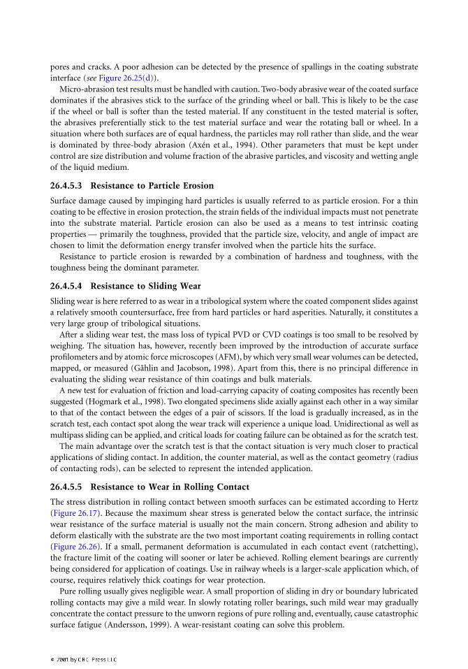
26.4.5.5 Resistance to Wear in Rolling Contact
The stress distribution in rolling contact between smooth surfaces can be estimated according to Hertz(Figure 26.17). Because the maximum shear stress is generated below the contact surface, the intrinsicwear resistance of the surface material is usually not the main concern. Strong adhesion and ability todeform elastically with the substrate are the two most important coating requirements in rolling contact(Figure 26.26). If a small, permanent deformation is accumulated in each contact event (ratchetting),the fracture limit of the coating will sooner or later be achieved. Rolling element bearings are currentlybeing considered for application of coatings. Use in railway wheels is a larger-scale application which, ofcourse, requires relatively thick coatings for wear protection.
Pure rolling usually gives negligible wear. A small proportion of sliding in dry or boundary lubricatedrolling contacts may give a mild wear. In slowly rotating roller bearings, such mild wear may graduallyconcentrate the contact pressure to the unworn regions of pure rolling and, eventually, cause catastrophicsurface fatigue (Andersson, 1999). A wear-resistant coating can solve this problem.
The stress distribution in sliding between nonconforming surfaces resembles that of rolling contact,if the friction coefficient is below 0.3. Practical examples include the cam and tappet contact of a carengine, or the contact between gear teeth, both of which are designed to operate in the boundarylubrication regime. This means that the friction coefficient typically amounts to 0.10 to 0.15, and themaximum shear stress is not confined to the contact surface. Consequently, good adhesion and the abilityto deform elastically with the substrate are required for coatings in this kind of application, as it is forrolling element bearings.
26.4.6 Tribological Response of Coated Components
The end users of coated components are recommended to make the final evaluation of the tribologicalresponse in field tests or in component tests (i.e., tests where the actual component is evaluated underrealistic conditions). Any simplified laboratory test can deviate from the actual situation as to nominaland real contact pressure, sliding speed, heat conductivity and capacity, ambient cooling, etc., andcorrelation to the real case is hazardous. Examples of components that can be field-tested relatively easilyare cutting tools and other relatively small components with limited life. Large and expensive formingtools, for example, may have to be evaluated in simplified tests, preferably through smaller model toolsused in a pilot plant. It is sometimes possible to design a large component incorporating small insertsthat can be easily exchanged and act as test surfaces. In carefully designed tests, these inserts will experiencethe same tribological conditions as the actual component.
26.4.7 Failure Analysis of Coating Composites
Premature failure of coating composites almost always involves local or extensive coating detachment.Given the task to analyze the cause of a premature failure of a coated component and suggesting meansto improve it, the following questions should be addressed:
1. Substrate condition: Is the hardness, chemical composition, etc., of the substrate that which isdesired?
2. Substrate surface preparation: Is the substrate too rough? Has the grinding been too severe, thusgenerating, for example, untempered martensite, decarburization, or thermal softening? Are thereany residual impurities in the interface?
3. Type of coating failure: Has the failure been initiated mechanically, thermally, or chemically?
FIGURE 26.26 (a) Test designed to simulate the tribological situations in rolling contact. The cylindrical test pinis rotated against two normally loaded disks. (b) Typical coating wear after rolling contact simulation of TiN-coatedHSS. The original grinding topography is seen at the left in the figure. Initially, the surface is smoothed due to a verymild wear mechanism. After a critical number of revolutions, the coating starts to spall.
Of course, these three causes require different remedies. Mechanical failure has been thoroughly treatedin Section 26.4. If thermal softening or decomposition of coating and/or substrate is suspected, themechanical properties at elevated temperatures should be emphasized. A chemical cause of coatingdetachment can be related to galvanic corrosion in the interface. A corrosion-resistant coating on acorrosion-resistant material can form a galvanic cell if chemical potentials deviate. In such a case, it isimportant that the coating is free from pin holes or cracks, running down to the substrate. If thecoating/substrate material combination can be changed, increasing the coating thickness or introducinga multilayered coating structure might improve the situation (Wiklund et al., 1996).
In the case of excessively rapid coating wear, again start by making sure if the dominant wear mech-anism is mechanical or chemical. This is suitably done in the SEM, looking for any scratches, indentations,fracture surfaces, or any other sign of mechanical damage. It may be useful to also study metallographiccross-sections, because mechanical damage is accompanied by sub-surface deformation. Absence of suchfeatures indicates that chemical attack is dominant.
26.5 Visions and Conclusions
The evolution of surface engineering has just begun. Sandvik Coromant introduced the first tribologicalCVD coating (TiC) in 1969 to protect cemented carbide cutting tools, and the first PVD coating (TiN)was applied to high-speed steel in the late 1970s for the same reason. These two are still considered tobe among the very best tribological coating materials, even though new improved PVD and CVD coatingshave evolved and proved superior in specific applications. During the last decade, the number of newcoating materials, structures, combinations, and applications has increased exponentially. We have onlyseen the very beginning of an evolution which in the future probably will encompass virtually allmechanical components.
Research will soon succeed in applying coatings to vital machine components of lightweight materials,thereby reducing the weight of machinery while maintaining or even improving performance and lifetime.Furthermore, many low-friction coatings may offer the same low-friction levels as those of boundarylubricated contacts (0.10 to 0.20). Thus, the need for lubrication of tools and machine components willdecrease, which will help to relieve some of today’s environmental stresses.
The current aim to coat light materials such as alloys based on Al, Ti, and Mg was pointed out inSection 26.3.3. Because these materials cannot resist the temperatures of most of today’s PVD and CVDprocesses (see Figure 26.6), there is an urgent need to develop deposition processes that involve consid-erably lower temperatures.
Metal alloying has proved successful in increasing the toughness of other coatings and bulk ceramics,and should be explored also for diamond.
The columnar structure of current PVD and CVD coatings makes them sensitive to stresses parallelto the plane of the coating. The fracture toughness of the best PVD coatings of today is only about onetenth that of the corresponding bulk ceramic material. However, there has been some pioneering workto overcome this drawback, reported by Veprek and Reprich (1995), by introducing second-phase par-ticles. It would be even more challenging to design coatings with grains elongated to fibers preferablyoriented in the plane of the coating. Such a structure should have the potential of being very tough.
Finally, there is a need for models that can predict the tribological response of coated components.This is most urgent for machine components (see Section 26.3.3). Given relevant information of theapplication, these models should preferentially consider the load-carrying capacity of the composite, andgenerate recommendations of the coating thickness and of coating and substrate materials properties interms of Young’s modulus, hardness, and toughness.
However, while awaiting analytical tools for coatings selection and design, one will have to rely onselective testing (see Hogmark and Jacobson, 1992a). Thus, the development of versatile and reliabletechniques for evaluation of coated components will continue to be important for the tribologicalassessment and development of new coating composites and their applications.
Acknowledgments
The authors gratefully acknowledge support from the Swedish Research Council for Engineering Sciences(TFR); the National Swedish Board for Technical and Industrial Development (NUTEK); the SwedishBoard for Strategic Research (SSF); Sandvik Coromant; Erasteel; Seco Tools; Balzers Sandvik; Tixon;Volvo; Scania; ABB; Duroc; SKF; and staff at the Tribomaterials Group at the Ångström Laboratory,Uppsala University.
References
Allen, S.M. and Thomas, E.L. (1998), The Structure of Materials, Wiley, New York.Andersson, S., (1999), Prediction of wear in rolling and sliding contacts, Proc. 21 IRG-OECD Meeting on
Wear of Engineering Materials, Amsterdam, March 25-26.Axén, N., Jacobson, S., and Hogmark, S. (1994), Influence of the hardness of the counterbody in three-
body abrasive wear — an overlooked hardness effect, Tribol. Int., 27, 233–241.Bell, T. (1975), Heat Treat. Met., 2, 39-49.Bell, T. (1997), New Directions in Tribology, Mech. Eng. Publication Ltd., World Trib. Congress, London, 121.Bergmann, E., Kaufmann, H., Schmid, R., and Vogel, J. (1990), Ion-plated titanium carbonitride films,
Surf. Coat. Technol., 42, 237-251.Blakely, J.N. (1964), Mechanical properties of vacuum-deposited gold films, J. Appl. Phys., 35, 1736.Blomberg, A., Olsson, M., and Hogmark, S. (1994), Wear mechanisms and tribo mapping of Al2O3 and
SiC in dry sliding, Wear, 171, 77-89.Brown, G.C. and Pryputniewicz, R.J. (1993), Measurement of Young’s modulus on thin films under static
and dynamic loading conditions, 302/SPIE, 2004 Interferometry, VI: Applications, 302.Chu, X., Barnett, S.A., Wong, M.S., and Sproul, W.D. (1993), Reactive unbalanced magnetron sputter
deposition of polycrystalline TiN/NbN superlattice coatings, Surf. Coat. Technol., 57, 13-18.Courtney, T.H. (1990), in Mechanical Behavior of Materials, McGraw-Hill, New York.Dingremont, N., Bergmann, B., and Collignon, P. (1995a), Application of duplex coatings for metal
injection moulding, Surf. Coat. Technol., 72, 157-162.Dingremont, N., Bergmann, B., Collignon, P., and Michel, H. (1995b), Optimisation of duplex coatings
built from nitriding and ion plating with continuous and discontinuous operation for constructionand hot working steels, Surf. Coat. Technol., 72, 163-168.
Farges, G., Bosch, J.P., and Bergmann, E. (1989), Friction and adhesive wear behavior of W-C coatingsagainst steel and titanium nitride, Wear, 135, 1-14.
Gåhlin, R. and Jacobson, S. (1998), A novel method to map and quantify wear on a micro-scale, Wear,222, 93–102.
Gåhlin, R., Alahelisten, A., and Jacobson, S. (1996), The effects of compressive stresses on the abrasionof diamond coatings, Wear, 196, 226–233.
Gåhlin, R., Larsson, M., Hedenqvist, P., Jacobson, S., and Hogmark, S. (1997), The crater grinder methodas a means for coating wear evaluation — an update, Surf. Coat. Technol., 90, 107–114.
Gunnars, J. (1997), On Fracture of Layered Materials, Ph.D. thesis No. 37, Luleå University of Technology,Sweden.
Hedenqvist, P., Olsson, M., and Hogmark, S. (1992), Tribological studies of various magnetic heads andthin-film rigid disks, Wear, 153, 65-78.
Hellgren, N. (1999), Sputtered Carbon Nitride Thin Films, Ph.D. thesis No. 604, Linköping University,Sweden.
Helmersson, U., Sundgren, J.-E., and Greene, J.E. (1986), Microstructure evolution in TiN films reactivelysputter deposited in multiphase substrates, J. Vac. Sci. Technology, A4, 500.
Hirvonen, J.-P., Koskinen, J., Jervis, J.R., and Nastasi, M. (1996), Present progress in the development oflow friction coatings, Surf. Coat. Technol., 80, 139.
Hoffman, R.W. (1989), Nanomechanics of thin films: Emphasis: Tensile properties, Mat. Res. Soc. Proc.,130, 295.
Hogmark, S. and Jacobson, S. (1992a), Hints and guidelines for tribotesting and evaluation, JSTLE, May,401-409.
Hogmark, S., Jacobson, S., and Vingsbo, O. (1992b), In Friction Lubrication and Wear Technology, ASMHandbook 18, 176.
Hogmark, S., Hollman, P., Alahelisten, A., and Hedenqvist, P. (1996), Direct current bias applied to hotflame diamond deposition produces smooth low friction coatings, Wear, 200, 225-232.
Hogmark, S., Hedenqvist, P., and Jacobson, S. (1997a), Tribological properties of thin hard coatings —Demands and evaluation, Surf. Coat. Technol., 90, 247-257.
Hogmark, S., Jacobson, S., Hedenqvist, P., and Olsson, M. (1997b), Surface Characterisation, A User’s Sour-cebook, Brune, Hellborg, Whitlow and Hunderi (Eds.), Wiley-VCH, Weinheim, Germany, 624–644.
Hogmark, S., Jacobson, S., and Wänstrand, O. (1998), Universal test for friction, wear and lubrication,Swedish patent DNR 9802017-5.
Hollman, P. (1997a), Micro- and Nanocrystalline Diamond Coatings with Extreme Wear Resistance andUltra Low Friction, Acta Universitatis Upsaliensis Dissertation in Science and Technology 325, ISBN91-554-4084-3.
Hollman, P., Larsson, M., Hedenqvist, P,. Hogmark, S. (1997b), Tensile testing as a method for deter-mining the Young’s modulus of thin hard coatings, Surf. Coat. Technol., 90, 234-238.
Holmberg, K. and Matthews, A. (1994), Coatings Tribology, Tribology series, 28, Elsevier.Johansson, E. (1993), Surface modification in tribology, Acta Universitatis Upsaliensis Dissertation in
Science and Technology 433 ISBN 91-554-3061-6, Paper VII.Jönsson, B. and Hogmark, S. (1984), Hardness measurements of thin films, Thin Solid Films, 114, 257-269.Karner, J., Pedrazzini, M., Reineck, I., Sjöstrand, M.E., and Bergmann, E. (1996), CVD diamond coated
cemented carbide cutting tools, Mater. Sci. Eng. A: (Structural Materials: Properties, Microstructureand Processing), A209, 402-410.
Kassman, Å., Jacobson, S., Erickson, L., Hedenqvist, P., and Olsson, M. (1991), A new test method forthe intrinsic abrasion resistance of thin coatings, Surf. Coat. Technol., 50, 75–84.
Khruschov, M.M. (1974), Principles of abrasive wear, Wear, 28, 68-88.Larsson, M. (1996a), Ph.D. thesis, Acta Universitatis Upsaliensis Dissertation No. 191, Uppsala University,
Sweden.Larsson, M., Hollman, P., Hedenqvist, P., Hogmark, S., Wahlström, U., and Hultman, L. (1996b), Dep-
osition and microstructure of PVD TiN-NbN multilayered coatings, Surf. Coat. Technol., 86/87,351-356.
Mao, K., Sun, Y., and Bell, T. (1994), Contact mechanics of engineering surfaces: state of the art, Surf.Eng., 10, 297-306.
Nix, W.D. (1989), Mechanical properties of thin films, Metallurgical Trans., 20a, 2225.Nordgren, A. and Melander, A. (1988), Tool wear and inclusion behavior during turning of a Ca-treated
quenched and tempered steel using coated cemented carbide tools, Proc. 1st Int. Conf. on theBehaviour of Materials in Machining, Stratford-upon-Avon, U.K., Nov., paper 20.
Nordin, M., Larsson, M., and Hogmark, S. (1998), Mechanical and tribological properties of multilayeredPVD TiN/CrN, TiN/NbN, TiN/MoN and TiN/TaN, Surf. Coat. Technol., 106, 234-241.
Nordin, M., Larsson, M., and Hogmark, S. (1999), Wear resistance of multilayered PVD TiN/TaN coatingson HSS, Surf. Coat. Technol., 120-121, 528-534.
Oettel, H. and Wiedemann, R. (1995), Residual stresses in PVD hard coatings, Surf. Coat. Technol., 76/77,265–273.
Oliver, W.C. and Pharr, G.M. (1992), An improved technique for determining hardness and elasticmodulus using load and displacement sensing indentation experiments J. Mater. Res., 7, 1564-1583.
Palmai, Z. (1984), Formation of non-metallic protective layers on high speed tools, Met. Technol., 11,34-37.
Ramsey, P.M., Chandler, H.W., and Page, T.F. (1991), Bending tests to estimate the through-thicknessstrength and interfacial shear strength in coated systems, Thin Solid Films, 201, 81-89.
Rickerby, D.S., Bellamy, B.A., and Jones, A.M. (1987), Internal stress and microstructure of titaniumnitride coatings, Surf. Eng., 3, 138.
Rickerby, D.S. and Bull, S.J. (1989), Engineering with surface coatings. The role of coating microstructure,Surf. Coat. Technol., 39/40, 315.
Rickerby, D.S. and Burnett, P.J. (1987), The wear and erosion resistance of hard PVD coatings, Surf. Coat.Technol., 33, 191-211.
Röll, K. (1976), Analysis of stress and strain distribution in thin films and substrates, J. Appl. Phys., 47,3224.
Rouzaud, A., Barbier, E., Ernoult, J., and Quesnel, E. (1995), A method for elastic modulus measurementsof magnetron sputtered thin films dedicated to mechanical applications, Thin Solid Films, 270, 270.
Rutherford, K.L. and Hutchings, I.M. (1996), A microabrasive wear test with particular application tocoated systems, Surf. Coat. Technol., 79, 231-239.
Rutherford, K.L. and Hutchings, I.M. (1997), Theory and application of a micro-scale abrasive wear test,J. Testing Eval., 25, 250-260.
Schultrich, B., Scheibe, H.-J., Grandremy, G., and Schneider, D. (1984), Elastic modulus of amorphouscarbon films, Phys. Stat. Sol. (a), 145, 385.
Selinder, T.I., Nordin, M., Larsson, M., Hedenqvist, P., Östlund, Å., Hogmark, S., and Sjöstrand, M.E.(1998), Performance of PVD TiN/TaN and TiN/NbN superlattice coated cemented carbide toolsin stainless steel machining Surf. Coat. Technol., 105, 51-55.
Shinn, M., Hultman, L., and Barnett, S.A. (1992), Growth, structure and microhardness of epitaxialTiN/NbN superlattices, J. Mater. Res., 7, 901-911.
Sjöström, H., Hultman, L., Sundgren, J.-E., Hainsworth, S.V., and Page, T.F. (1996), Structural andmechanical properties of L. carbon nitride CNx (0.2 ≤ x ≤ 0.35) films, Theunissen-GSAM, J. Vac.Sci. Technol., 14, 56-62.
Sproul, W.D. (1994), Multilayer, multicomponent, and multiphase physical vapor deposition coatingsfor enhanced performance, J. Vac. Sci. Technol., A12, 1595.
Sproul, W.D., Graham, M.E., Wong, M.S., Lopez, S., Li, D., and Scholl, R.A. (1995), Reactive direct currentmagnetron sputtering of aluminium oxide coatings, J. Vac. Sci. Technol., 13 1188.
Sproul, W.D. (1996a), Physical vapor deposition tool coatings, Surf. Coat. Technol., 81, 1.Sproul, W.D. (1996b), Reactive sputter deposition of superhard polycrystalline nanolayered coatings,
layered materials for structural applications, Symp. Mater. Res. Soc., Pittsburgh, PA, ix+314, 47-55.Steinmann, P.A. and Hintermann, H.E. (1989), A review of the mechanical tests for assessment of thin-
film adhesion, J. Vac. Sci. Technol., A7, 2267-2272.Steinmann, P.A., Tardy, Y., and Hintermann, H.E. (1987), Adhesion testing by the scratch test method: the
influence of intrinsic and extrinsic parameters on the critical load, Thin Solid Films, 154, 333-349.Stoney, G.G. (1909), The tension of metallic films deposited by electrolysis, Proc. R. Soc. London, A82, 172.Sue, J.A. (1992), X-ray elastic constants and residual stress of textured titanium nitride coating, Surf.
Coat. Technol., 54/55, 154.Sugimura, Y., Lim, P.G., Shih, C.F., and Suresh, S. (1995), Fracture normal to a bimaterial interface: effects
of plasticity on crack-tip shielding and amplification, Acta Metall. Mater., 43, 1157.Suryanarayana, C. (1995), Nanocrystalline materials, Int. Mat. Rev., 40, 41.Todorova, S., Helmersson, U., Barnett, S.A., Sundgren, J.-E., and Greene, J.E. (1987), TiN-VN strained
layer superlattice hard coatings, IPAT 87. 6th Int. Conf. on Ion and Plasma Assisted Techniques, CEPConsultants, Edinburgh, U.K., xi+481,248.
Townsend, P.H. and Barnett, D.M. (1987), Elastic relationships in layered composite media with approx-imation for the case of thin films on a thick substrate, J. Appl. Phys., 62, 4438.
Venkatraman, R., Besser, P.R., Brennan, S., and Brauman, J. (1992), Determination of strain distributionsin aluminium thin films as a function of temperature by the use of synchrotron grazing incidenceX-ray scattering, Mat. Res. Soc. Symp. Proc., 239, 227.
Veprek, S. and Reprich, S. (1995), A concept for the design of novel superhard coatings, Thin Solid Films,268, 64.
Vingsbo, O., Hogmark, S., Jönsson, B., and Ingemarsson, A. (1986), A., Microindentation Techniques inMaterials Science and Engineering, Blau, P.J. and Lawn, B.R. (Eds.), ASTM publication 889, 257-271.
Voevodin, A.A., Donley, M.S., and Zabinski, J.S. (1997), Pulsed laser deposition of diamond-like carbonwear protective coatings: a review, Surf. Coat. Technol., 92, 42-49.
Voevodin, A.A., O’Neill, J.P., and Zabinski, J.S. (1998), Tribological performance and tribochemistry ofnanocrystalline WC/amorphous diamond-like carbon composites, Thin Solid Films, 342, 194-200.
Wiklund, U., Hedenqvist, P., Hogmark, S., Stridh, B., and Arbell, M. (1996), Multilayer coatings ascorrosion protection of Zircalloy, Surf. Coat. Technol., 86-87, 530-534.
Wiklund, U., Hedenqvist, P., and Hogmark, S. (1997), Multilayer cracking resistance in bending, Surf.Coat. Technol., 97, 773-778.
Wiklund, U. and Larsson, M. (1999a), Low friction PVD titanium-carbon coatings, Wear, 241, 234-238.Wiklund, U., Gunnars, J., and Hogmark, S. (1999b), Influence of residual stresses on fracture and
delamination of thin hard coatings, Wear, 232, 262-269.Windischmann, H. (1992), Intrinsic stress in sputter-deposited thin films, Crit. Rev. Solid State and Mater.
Sci., 17, 547.