Embed Size (px)
Citation preview

A diesel engine uses diesel fuel. It generates high power at
low speeds and is solidly constructed. The fuel efficiency is
better than that of a gasoline engine.
What is Diesel Engine

How It Works?

Diesel vs Gasoline

Features of Diesel Engine Advantages
1. Economical fuel consumption due to better thermal efficiency and economical
operation due to lower cost of fuel.
2. Greater durability and less troubles due to lack of ignition system.
3. Wider range of usable fuel and greater flexibility in the use of substitute fuels.
4. Torque variation is smaller over a wide range of speed, to allow greater flexibility
and ease of operation.
Disadvantages
1. Greater vibration and noise due to maximum pressure at combustion being twice
that of gasoline engines.
2. Close selection of material and more rugged construction required to withstand the
higher pressure. This results in larger weight per horsepower and higher production
cost.
3. Fuel injection system requires higher precision manufacture, resulting in making
maintenance difficult.
4. Larger capacity starters and batteries required due to the large compression ratio
making necessary greater force to turn engine.

Features of Diesel Engine

1. Combustion chamber
The diesel engine is not equipped with
an ignition system containing spark
plugs. Instead, the heat that is
generated during compression causes
the fuel to self- ignite. So the
compression ratio is highly set up.
2. Preheating system
To facilitate the start-ability of the
engine, the diesel engine has a
preheating system that uses glow
plugs etc. to heat the intake air.
3. Fuel system
The diesel engine has an injection
pump and injection nozzles to inject
fuel into the combustion chamber at a
high pressure.
Diesel Engine Description

Diesel vs Gasoline
Diesel Engine

Combustion Chamber
Direct injection type
(Direct combustion chamber)
Auxiliary combustion
chamber type
Pre-combustion Chamber
Swirl Chamber
Air Cell

Combustion Chamber
Direct Injection In-direct Injection

Direct Injection System
Direct Injection System Combustion Chamber Shapes

Direct Injection System Advantages
1. Combustion chamber shape is simple so that thermal efficiency is high and
fuel consumption is low.
2. Starts readily from cold state without using special starting aids (glow plugs),
even in the case of small engines with compression ratio of around 15.
3. Suited for high power engines due to simplicity of cylinder head construction
and small heat distortion.
Disadvantages
1. Sensitive to fuel quality and requires good grade fuel.
2. Higher fuel injection pressure required.
3. Nozzle troubles frequent and nozzle life shorter due to use of multiple-
orifice nozzle. Spray condition has large effect on engine performance.
4. When compared to auxiliary chamber type, turbulence is weaker so that
high speed operation is difficult.

Auxiliary Combustion Chamber System
a) Pre Combustion Chamber Type
Combustion Chambers of Pre Combustion Chamber Type
(Ricardo Comet)

a) Pre Combustion Chamber Type
Advantages
1. Wide range of fuel can be used. Relatively poor fuel can be used with
practically smokeless combustion.
2. Easy to maintain as the fuel injection pressure is relatively low and the
engine is comparatively insensitive to changes in injection timing.
3. Due to use of throttle nozzles, diesel knock is reduced and engine
operates more quietly.
Disadvantages
1. Construction cost is higher due to complicated cylinder design.
2. Larger starter is required. Starting performance is bad and glow plugs
must be used.
3. Fuel consumption rate is higher.

b) Swirl Chamber Type
Combustion Chamber of Swirl Type

b) Swirl Chamber Type
Advantages
1. High engine speed can be attained due to utilization of large compression
turbulence.
2. Small nozzle troubles due to use of pin type nozzles (refer to the paragraph on
injection nozzles)
3. Wide engine speed range possible and smoother operation, making this type
suited for automotive use.
Disadvantages
1. Complicated cylinder head or cylinder block construction.
2. Thermal efficiency and fuel consumption rate are both inferior to those of
direct injection system.
3. Glow plugs are required but are not very effective due to the large size of the
swirl chamber.
4. Diesel knock is relatively greater at low speed.

C) Air Cell Type
Air Cell Type Combustion Chambers

C) Air Cell Type
Advantages
1. Engine operation is quieter as the combustion takes place more
gradually.
2. Fuel is injected directly into the combustion chamber so that ease of
starting is next to direct injection system, and glow plugs are not used in
many of the cases.
3. Less nozzle trouble due to use of pin type nozzle.
Disadvantages
1. Fuel injection timing has large effect on engine performance.
2. High exhaust temperature due to large amount of after burning.
3. Fuel consumption rate is high.

Sufficient compressed heat
cannot be attained during a
cold start or a low-
temperature operation. The
preheating system heats the
intake air to enhance the
ignitability of the fuel. This
system uses battery current to
heat the intake air.
There are two types of preheating systems:
A. Glow-plug type - Heats the combustion chamber
B. Intake heater type - Heats the intake air
1. Glow-plug
2. Heat coil
Pre-heating System

Heater Plug System
Heater Plug

Heater Plug System

Heater Plug System

Heater Plug System
Thermo start System
Thermo start Heating

Thermo start System
Layout of fuel system incorporating
Thermo start Heating

Thermo start System
Aerosol Type Spray

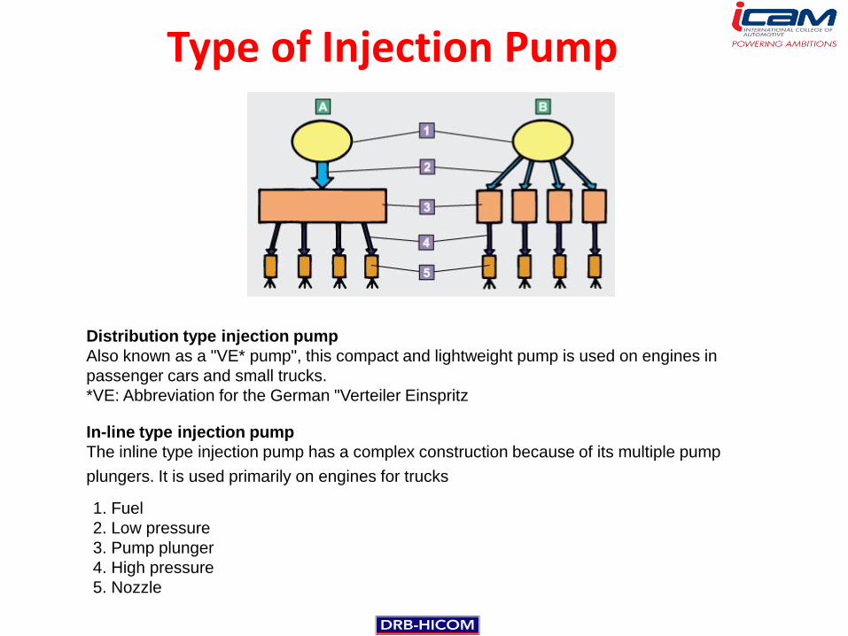
The fuel system of the diesel engine injects highly pressurized fuel into a combustion
chamber in which air has been compressed to a high pressure. This requires special
equipment that is not used in the gasoline engine.
1. Fuel tank
2. Fuel filter with sedimentary
3. Injection pump
4. Injection nozzle
Fuel Injection System

Fuel System
Fuel Injection System

This device removes dust and water from fuel to protect the injection pump and
injection nozzles that contain precision parts. Dust and water must be removed from the
fuel to prevent the injection pump from seizing or rusting as the injection pump is
lubricated with diesel fuel.
1. Priming pump
2. Filter
3. Sedimenter
Fuel Filter

a) Conventional Fuel Filter
Fuel flows up-wards
through filter element

b) Agglomerator Fuel Filter
Fuel flows down through filter, water is
collected in sedimenter chamber

c) Sedimenter Fuel Filter
Sedimenter – large droplets of water and dirt fall to the bottom of the
chamber. These be easily seen and cleaned out as necessary
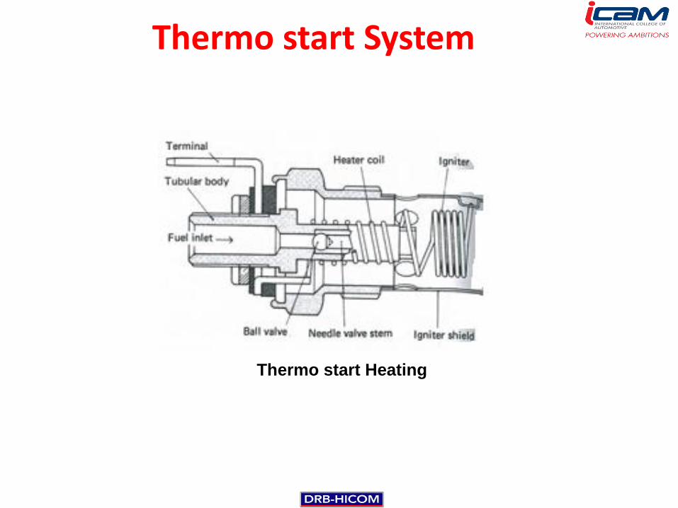
Distribution type injection pump
Also known as a "VE* pump", this compact and lightweight pump is used on engines in
passenger cars and small trucks.
*VE: Abbreviation for the German "Verteiler Einspritz
In-line type injection pump
The inline type injection pump has a complex construction because of its multiple pump
plungers. It is used primarily on engines for trucks
1. Fuel
2. Low pressure
3. Pump plunger
4. High pressure
5. Nozzle
Type of Injection Pump

Fuel Injection System
Fuel Injection System

Fuel Injection Pump
Fuel Injection Pump

Fuel Injection Pump
Typical four-cylinder Minimec Pump

Fuel Injection Pump
Cross-section of Simms Minimec in-line Pump

Fuel Injection Pump

Fuel Injection Pump Tappet

Pump Element
Pump Element

Pump Element
Pump Element

Injection Pump Operation
Pump Element

Injection Pump Operation
Pump Element

Control rack
Control Rack

Fuel Pump
Fuel Pump Operation

Fuel Pump

Fuel Pump
Diaphragm feed pump – low pressure

Fuel Pump
Diaphragm-plunger feed pump – High
pressure

Governor
Pneumatic Governor

Governor
Layout of pneumatic governor

Governor
Delivery Valve

Governor

Governor

Governor
Injection Control Mechanism
(A) (B) (C)

Timer
Automatic Timer

The injection pump pressurizes the fuel and pumps it to the injection nozzles.
The fuel injection volume and the fuel injection timing are mechanically controlled in accordance
with the amount of effort that is applied to the accelerator pedal and the engine speed.
Injection Pump (VE Type)

Injection Pump (VE Type)
Injection Pump Schematic View

Injection Pump (VE Type)
Illustrative Comparison of in-line and
Distributor-injection Pumps

Injection Pump (VE Type)

Injection Pump Operation (VE Type)
Injection pump sectional view

Fuel Injection System
Fuel Injection System
Fuel Injection System
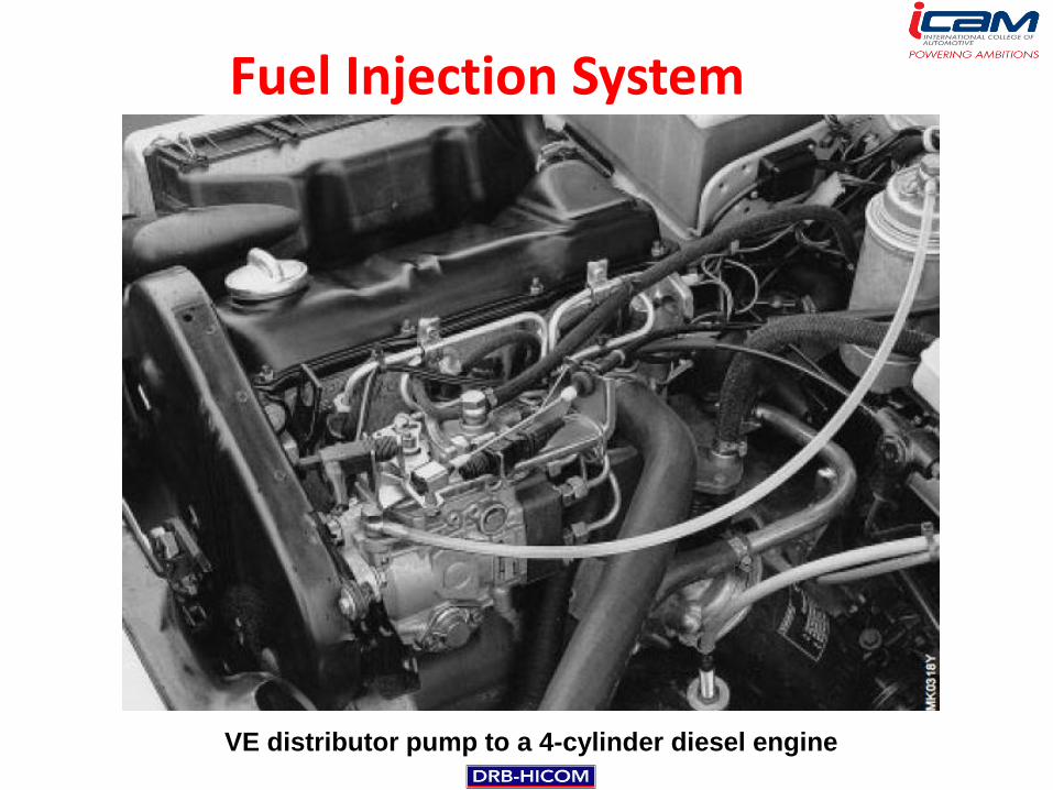
VE distributor pump to a 4-cylinder diesel engine

Subassemblies
The Subassemblies and their functions

Subassemblies
1. Vane-type fuel-supply pump with pressure regulating valve:
Draws in fuel and generates pressure inside the pump.
2. High-pressure pump with distributor: Generates injection
pressure, delivers and distributes fuel.
3. Mechanical (flyweight) governor: Controls the pump speed and
varies the delivery quantity within the control range.
4. Electromagnetic fuel shutoff valve: Interrupts the fuel supply.
5. Timing device: Adjusts the start of delivery (port closing) as a
function of the pump speed and in part as a function of the load.

Subassemblies
The Subassemblies and their configurations

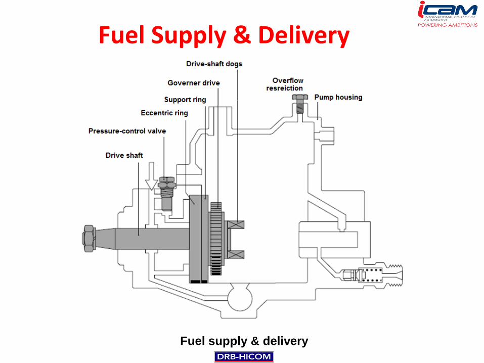
Fuel Supply & Delivery
Fuel supply & delivery
Fuel tank
Fuel line
(Suction
pressure)
Fuel filter Distributor
Injection
pump
High-pressure
fuel-injection line
Injection
Nozzle
Fuel-return line
(pressure less)
Sheathed-element
glow plug
Fuel Supply & Delivery
Fuel supply & delivery

Vane-type fuel supply pump
Vane-type fuel-supply pump with impeller on the drive shaft

Vane-type fuel supply pump

Feed Pump
Vane-type fuel supply pump

Regulating Valve
Regulating Valve

Pressure Control Valve
Pressure-control valve

Overflow Restriction
Overflow restriction

High Pressure Stage
Pump assembly for generation and delivery of high
pressure in the distributor-pump interior

Pressure Distributor
The cam plate rotates against the roller ring, whereby its cam track follows the
rollers causing it to lift (for TDC) and drop back again (for BDC)

High Pressure Stage
Pump assembly with distributor head

Distributor plunger with stroke and delivery phases:
Entry of fuel:
Shortly before TDC, the inlet passage is opened. During the
plunger’s return stroke to BDC, the high-pressure chamber is
filled with fuel and transverse cutoff bore is closed again. The
outlet-port passage is also closed at this point.
Distributor Plunger Phases

Distributor Plunger Phases
Distributor plunger with stroke and delivery phases:
Inlet passage closes:
At BDC, the metering slot (1) closes the inlet passage, and the
inlet passage, and the distributor slot (2) opens the outlet port.

Distributor Plunger Phases
Distributor plunger with stroke and delivery phases:
Fuel delivery:
During the plunger stroke towards TDC (working stroke), the
plunger pressurizes the fuel in the high-pressure chamber (3).
The fuel travels through the outlet-port passage (4) to the
injection nozzle.

Distributor plunger with stroke and delivery phases:
End of delivery:
Fuel delivery ceases as soon as the control collar (5) opens the
transverse cutoff bore (6).
Distributor Plunger Phases

Distributor head with high-pressure chamber

Delivery Valve
Delivery Valve with return – flow restriction

Delivery Valve
Constant – Pressure Valve

Mechanical Engine Speed Control (Governing)
Distributor injection pump with governor assembly, comprising flyweight
governor and lever assembly

Mechanical Engine Speed Control (Governing)
Governor functions;
•The limitation of the engine’s maximum speed.
•Keep the engine speeds constant, such as idle speed range, or of the complete speed range, between idle and maximum speed.

Governor Characteristic
Minimum-maximum
speed governor
Variable-speed
governor
1. Start quantity
2. Full-load delivery
3. Torque control (positive)
4. Full-load speed regulation
5. Idle

Variable-speed Governor Operation Start Position

Variable-speed Governor Operation Idle position

Variable-speed Governor Operation Increasing engine speed

Variable-speed Governor Operation With falling engine speed

Minimum-maximum-speed Governor Operation
Idle setting

Minimum-maximum-speed Governor Operation
Idle setting
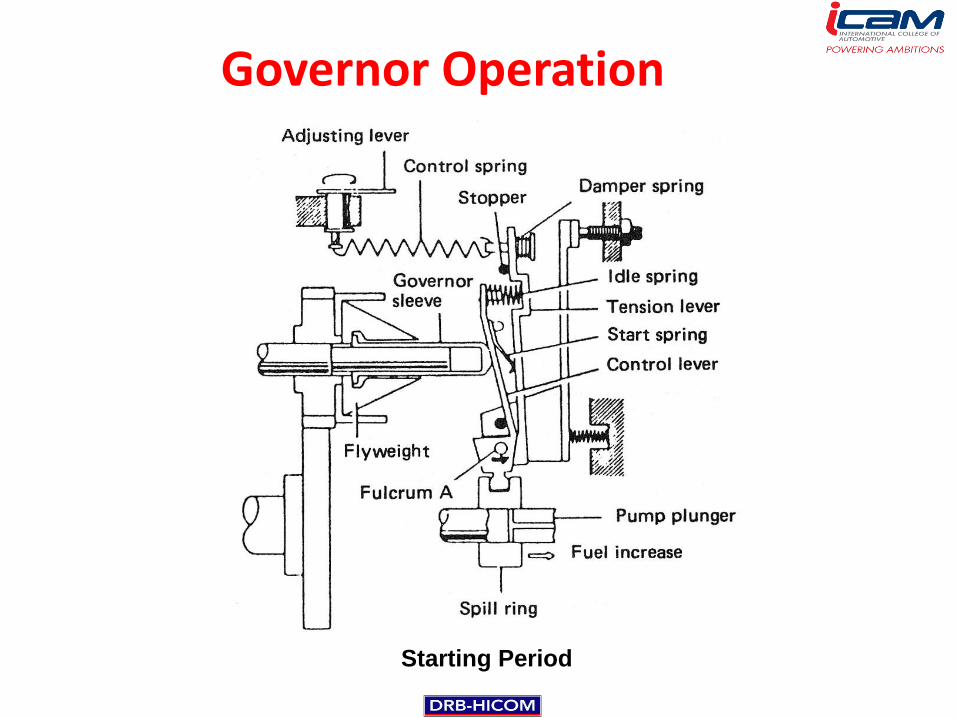
Starting Period
Governor Operation

Idling Operation Period
Governor Operation

Governor Operation
Full-Load Operation Period

Governor Operation
Maximum Speed Control Period

Timing Device
Distributor injection pump with timing device

Timing Device
Initial position

Timing Device
Operation position

Automatic Timer
Hydraulic Timer

Automatic Timer
Hydraulic Timer

Shutoff Device
Electrical shutoff device (Pull Solenoid)

Shutoff Device
Mechanical shutoff device

Injector
• To break down the measured quantity of fuel from the injector pump.
• To atomize the fuel into such a condition that it will readily mix with the air in the combustion chamber.
• To do this the fuel is subjected to a high pressure and then forced through one or several small holes.

Injector
Section through injector

Injector
Typical Leyland Injector

Injector
Simms fuel injector

Injector
Section through a Gardner injector (sprayer)

Nozzle
Type of Nozzle Construction

Hole-type Nozzle

Hole-type Nozzle
• Single or multi-hole – up to 12 holes.
• Hole sizes from 0.2mm upwards.
• Operating pressure adjustable and vary between 15 000 and 20 000 kN/m2 (2100 and 3500 lbf/in2)

Hole-type Nozzle
• Size and length of the hole affecting the depth and penetration of the spray into the combustion chamber.

Pintle-type Nozzle
• Single-hole nozzle with the end of the needle extended to form a pin or pintle which protrudes through the hole in the nozzle body.
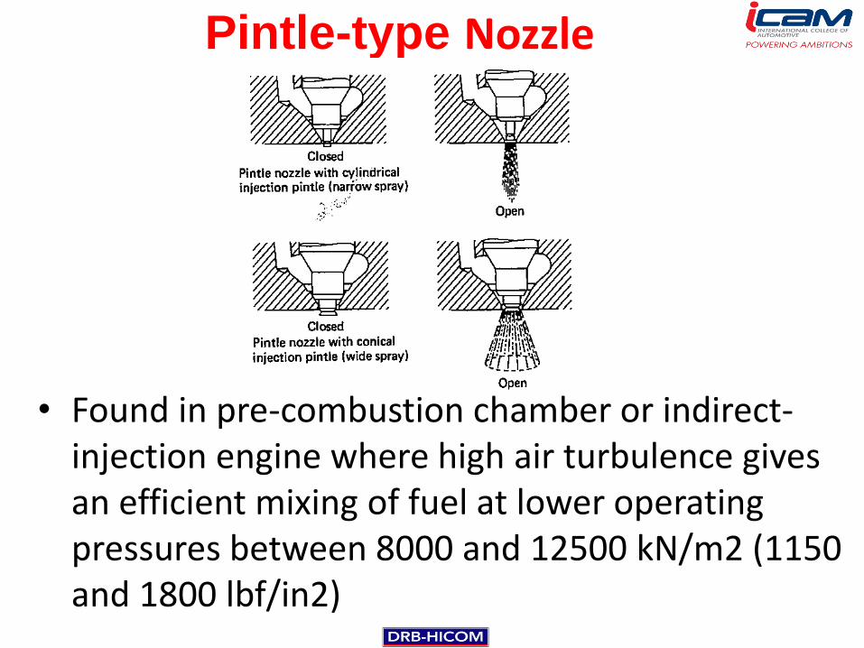
Pintle-type Nozzle
• Found in pre-combustion chamber or indirect-injection engine where high air turbulence gives an efficient mixing of fuel at lower operating pressures between 8000 and 12500 kN/m2 (1150 and 1800 lbf/in2)

Pintle-type Nozzle
• To give a pilot spray just prior to the main injection of fuel.
• To prevent ‘diesel knock’

Pintaux-type Nozzle

Nozzle Holder

Nozzle Holder
Section View of Nozzle Holder (Type KB)

Nozzle Holder

There are two types of injection
pumps used on diesel engines:
The mechanical injection pump that
mechanically controls the fuel
injection volume and timing.
The electronic injection pump that
uses an ECU (Electronic Control
Unit) in an EFI-D (Electronic Fuel
Injection Diesel) system.
A. Mechanical injection pump
B. Electronic injection pump
1. Injection pump
2. Injection nozzle
3. Timing belt
4. ECU
5. Sensors
Injection Pump

THANK YOU