Embed Size (px)
Citation preview
City of Sandy Transportation System Plan
Chapter 3: Modal Plans December 2011 Page 5
Chapter 3: Modal Plans This chapter includes plans directing transportation decisions to meet the needs of all modes of travel
within the City of Sandy through the year 2029. Documentation developed through the planning process
that led to these plans has been included in the appendix for reference. These include:
Technical Memorandum #2: Existing Conditions and Future Needs
Technical Memorandum #3: Transportation Alternatives and Improvement Strategies
Pedestrian System Plan The Pedestrian System Plan identifies projects to improve conditions for walking within the City of Sandy
– an important part of a balanced transportation network. Building upon existing local and regional
planning efforts, the plan reflects the valuable input offered by City staff, stakeholder groups, and Sandy
residents. The existing pedestrian system and identified deficiencies can be referenced in the appendix
(Technical Memorandum #2: Existing Conditions and Future Needs).
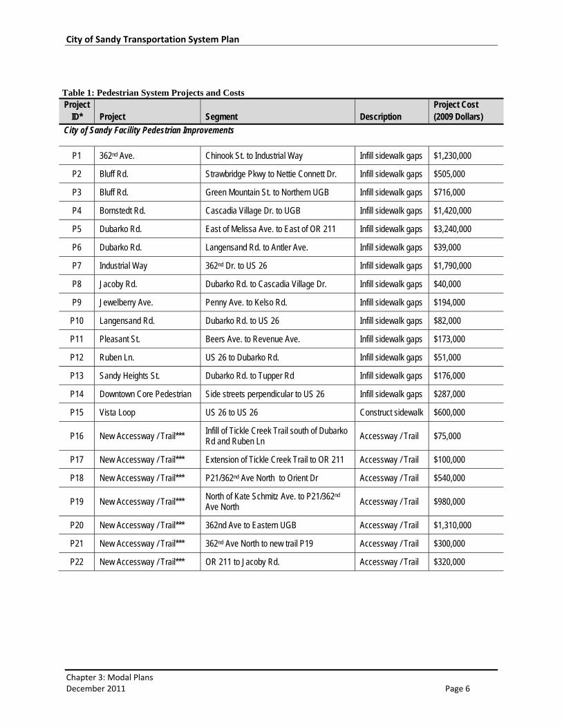
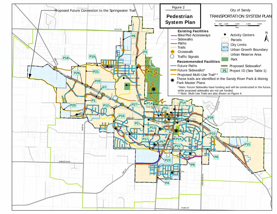
Recommended Pedestrian Projects The pedestrian plan builds upon Sandy’s existing system of sidewalks, paths, trails, and other pedestrian
infrastructure currently in place. The recommended projects, shown in Figure 2 and listed in Table 1,
represent the pedestrian component of the “Preferred Plan”, which consists of all transportation
improvements identified to support growth and connectivity needs through the year 2029. Projects
assumed for “Near Term” implementation, which represent a subset of the Preferred Plan that aligns
with anticipated funding, are listed in Chapter 4.
The pedestrian facility improvement projects in the Preferred Plan do not include new pedestrian
facilities that would be constructed as part of the recommended roadway projects identified in the
motor vehicle plan (Tables 7 and 8). It should be noted that future off‐road multi‐modal
trails/transportation corridors depicted on the system map represent conceptual alignments and are
shown for informational purposes. Additional routes, local trail connections, specific alignments and
designs will be identified in the Parks Master Plan, which will be the guiding document for all off‐road
multi‐modal trails/transportation corridors projects. In two instances, multi‐use trails and road
alignments are shown in approximately the same location. Conflicts between overlapping trail and
street alignments will be a matter of timing. If the trail is built prior to street construction, the street
design will accommodate the existing trail and its users. If the street is built first then trail planners may
choose to use sidewalks for some or all of the trail alignment or choose to link the trail to the pedestrian
network at certain locations.
City of Sandy Transportation System Plan
Chapter 3: Modal Plans December 2011 Page 6
Table 1: Pedestrian System Projects and Costs Project
ID* Project Segment Description Project Cost (2009 Dollars)
City of Sandy Facility Pedestrian Improvements
P1 362nd Ave. Chinook St. to Industrial Way Infill sidewalk gaps $1,230,000
P2 Bluff Rd. Strawbridge Pkwy to Nettie Connett Dr. Infill sidewalk gaps $505,000
P3 Bluff Rd. Green Mountain St. to Northern UGB Infill sidewalk gaps $716,000
P4 Bornstedt Rd. Cascadia Village Dr. to UGB Infill sidewalk gaps $1,420,000
P5 Dubarko Rd. East of Melissa Ave. to East of OR 211 Infill sidewalk gaps $3,240,000
P6 Dubarko Rd. Langensand Rd. to Antler Ave. Infill sidewalk gaps $39,000
P7 Industrial Way 362nd Dr. to US 26 Infill sidewalk gaps $1,790,000
P8 Jacoby Rd. Dubarko Rd. to Cascadia Village Dr. Infill sidewalk gaps $40,000
P9 Jewelberry Ave. Penny Ave. to Kelso Rd. Infill sidewalk gaps $194,000
P10 Langensand Rd. Dubarko Rd. to US 26 Infill sidewalk gaps $82,000
P11 Pleasant St. Beers Ave. to Revenue Ave. Infill sidewalk gaps $173,000
P12 Ruben Ln. US 26 to Dubarko Rd. Infill sidewalk gaps $51,000
P13 Sandy Heights St. Dubarko Rd. to Tupper Rd Infill sidewalk gaps $176,000
P14 Downtown Core Pedestrian Side streets perpendicular to US 26 Infill sidewalk gaps $287,000
P15 Vista Loop US 26 to US 26 Construct sidewalk $600,000
P16 New Accessway / Trail*** Infill of Tickle Creek Trail south of Dubarko Rd and Ruben Ln Accessway / Trail $75,000
P17 New Accessway / Trail*** Extension of Tickle Creek Trail to OR 211 Accessway / Trail $100,000
P18 New Accessway / Trail*** P21/362nd Ave North to Orient Dr Accessway / Trail $540,000
P19 New Accessway / Trail*** North of Kate Schmitz Ave. to P21/362nd Ave North Accessway / Trail $980,000
P20 New Accessway / Trail*** 362nd Ave to Eastern UGB Accessway / Trail $1,310,000
P21 New Accessway / Trail*** 362nd Ave North to new trail P19 Accessway / Trail $300,000
P22 New Accessway / Trail*** OR 211 to Jacoby Rd. Accessway / Trail $320,000
City of Sandy Transportation System Plan
Chapter 3: Modal Plans December 2011 Page 7
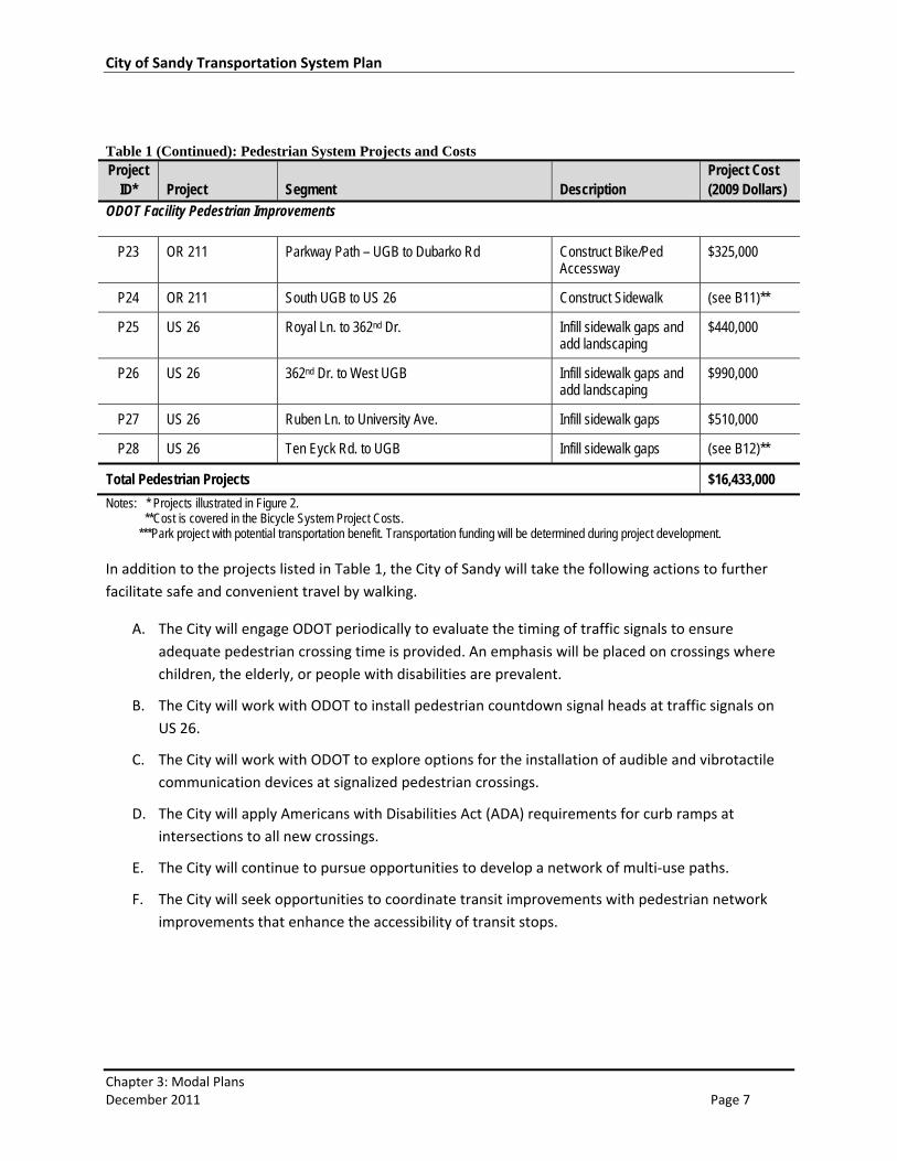
Table 1 (Continued): Pedestrian System Projects and Costs Project
ID* Project Segment Description Project Cost (2009 Dollars)
ODOT Facility Pedestrian Improvements
P23 OR 211 Parkway Path – UGB to Dubarko Rd Construct Bike/Ped Accessway
$325,000
P24 OR 211 South UGB to US 26 Construct Sidewalk (see B11)**
P25 US 26 Royal Ln. to 362nd Dr. Infill sidewalk gaps and add landscaping
$440,000
P26 US 26 362nd Dr. to West UGB Infill sidewalk gaps and add landscaping
$990,000
P27 US 26 Ruben Ln. to University Ave. Infill sidewalk gaps $510,000
P28 US 26 Ten Eyck Rd. to UGB Infill sidewalk gaps (see B12)**
Total Pedestrian Projects $16,433,000
Notes: * Projects illustrated in Figure 2. **Cost is covered in the Bicycle System Project Costs. ***Park project with potential transportation benefit. Transportation funding will be determined during project development.
In addition to the projects listed in Table 1, the City of Sandy will take the following actions to further
facilitate safe and convenient travel by walking.
A. The City will engage ODOT periodically to evaluate the timing of traffic signals to ensure
adequate pedestrian crossing time is provided. An emphasis will be placed on crossings where
children, the elderly, or people with disabilities are prevalent.
B. The City will work with ODOT to install pedestrian countdown signal heads at traffic signals on
US 26.
C. The City will work with ODOT to explore options for the installation of audible and vibrotactile
communication devices at signalized pedestrian crossings.
D. The City will apply Americans with Disabilities Act (ADA) requirements for curb ramps at
intersections to all new crossings.
E. The City will continue to pursue opportunities to develop a network of multi‐use paths.
F. The City will seek opportunities to coordinate transit improvements with pedestrian network
improvements that enhance the accessibility of transit stops.
!!!!
!!
!
!
!!
!
!
!
!
!
!!!
!!
!
! !!
!
!
!
!
!
!
!
!!
!
! ! !
!
! ! !
!
! ! !
!!
!
! !
!!
!
! !
!
!
!!
! !
!!
!
! !
!
!!
!!
!!
!!
!!
!!
!!
!!
!
!
!
!
! ! ! !
!!
!
!! !
!
!
! !
!!
!
!
!
!
!
!
!
! ! ! ! ! ! ! ! ! !
!!
!!
!!
!
!!
!
!
!
!
!
!
!
!!!!!
!!
!
!!
!
!!
!
!
!!
!!
!
!!!!!
!
!!!!!!
!!
!!
!!
!!!!!!
!!
!!
!!
!
!
!
!
!!!
,
,
,
,
, ,,
,,,!
!!
!
r
!
!
!
!
!
!
!
!
!
!!
!
!
!
r
RUBEN LN
HWY
211
BLUFF R
D
ORIENT DR
362N
D D
R
TEN
EYC
K R
D
LAN
GEN
SAN
D R
D
211
BORN
STE
DT
RD
GUNDERSON RDDU
BARKO RD
DUBARKO RD
VISTA LOOP
INDUSTRIAL WAY
BELL ST
JEW
LBER
RY
AVE
JAC
OBY
RD
VAN
FLE
ET A
VE
DAVI
S ST
PIONEER BLVD
PROCTOR BLVD
SANDY HEIGHTS ST
£¤26
£¤26
KELSO RD
MEI
NIG
AVE
TUPPER RD
SUNSET ST
TRUBEL RD
!
!
!
!
! !
!
!
!
!
!
!
!
! !
!
!
!
!
!
!
!
!
!
!
!
!
!
P9
P8
P7
P6
P5
P4
P3
P2
P1
P23
P21
P17
P28
P27
P26
P25
P24
P22
P20
P19P18
P16
P15
P14P14
P13
P12P11
P10
City Hall Post Office
Tupper Park
Cascadia Park
Knollwood Park
Public Library
Sandy River Park
Community Center
Sandy Bluff Park Jonsrud Viewpoint
Sandy High School
Bell Street Fields
Hamilton Ridge Park Meinig Memorial Park
Timberline Trails Park
Salmon Creek Estates Park
Sandy Skate Park
Barlow Ridge Park
Sandy High School
Sandy Elementary SchoolCedar Ridge Middle School
±
City of SandyTRANSPORTATION SYSTEM PLAN
0 1,000 2,000 3,000 4,000500Feet
Figure 2
Pedestrian System Plan
Existing Facilities
Recommended Facilities
*Note: Future Sidewalks have funding and will be constructed in the future, while proposed sidewalks are not yet funded.
Proposed Future Connection to the Springwater Trail
**Note: Multi-Use Trails are also shown on Figure 4.
TrailsPathsSidewalks
Crosswalk!Traffic Signals, Park
Urban Reserve AreaUrban Growth BoundaryCity LimitsParcelsActivity Centers!
Project ID (See Table 1)P1Proposed Sidewalks*
Bike/Ped Accessways
Future PathsFuture Sidewalks*Proposed Multi-Use Trail**
rThese trails are identified in the Sandy River Park & Meinig Park Master Plans
City of Sandy Transportation System Plan
Chapter 3: Modal Plans December 2011 Page 9
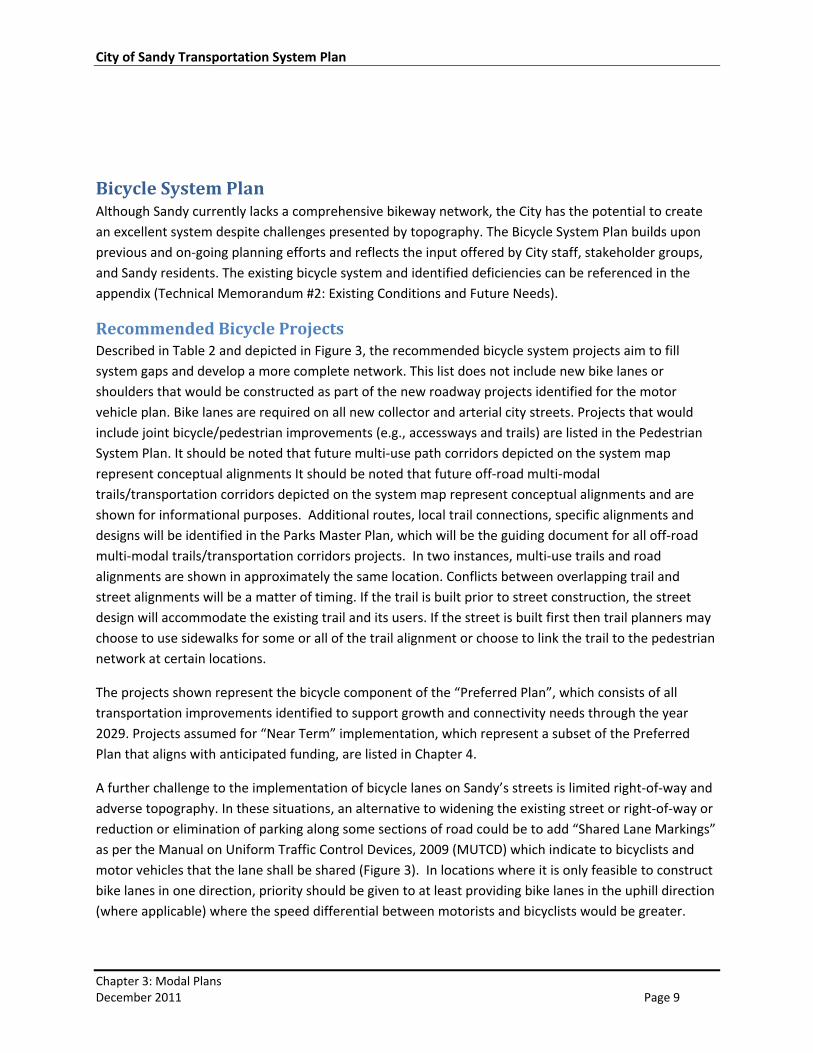
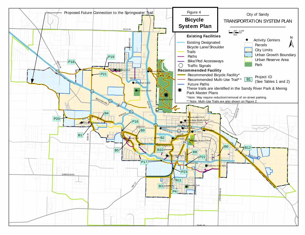
Bicycle System Plan Although Sandy currently lacks a comprehensive bikeway network, the City has the potential to create
an excellent system despite challenges presented by topography. The Bicycle System Plan builds upon
previous and on‐going planning efforts and reflects the input offered by City staff, stakeholder groups,
and Sandy residents. The existing bicycle system and identified deficiencies can be referenced in the
appendix (Technical Memorandum #2: Existing Conditions and Future Needs).
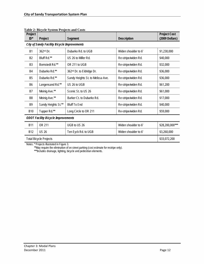
Recommended Bicycle Projects Described in Table 2 and depicted in Figure 3, the recommended bicycle system projects aim to fill
system gaps and develop a more complete network. This list does not include new bike lanes or
shoulders that would be constructed as part of the new roadway projects identified for the motor
vehicle plan. Bike lanes are required on all new collector and arterial city streets. Projects that would
include joint bicycle/pedestrian improvements (e.g., accessways and trails) are listed in the Pedestrian
System Plan. It should be noted that future multi‐use path corridors depicted on the system map
represent conceptual alignments It should be noted that future off‐road multi‐modal
trails/transportation corridors depicted on the system map represent conceptual alignments and are
shown for informational purposes. Additional routes, local trail connections, specific alignments and
designs will be identified in the Parks Master Plan, which will be the guiding document for all off‐road
multi‐modal trails/transportation corridors projects. In two instances, multi‐use trails and road
alignments are shown in approximately the same location. Conflicts between overlapping trail and
street alignments will be a matter of timing. If the trail is built prior to street construction, the street
design will accommodate the existing trail and its users. If the street is built first then trail planners may
choose to use sidewalks for some or all of the trail alignment or choose to link the trail to the pedestrian
network at certain locations.
The projects shown represent the bicycle component of the “Preferred Plan”, which consists of all
transportation improvements identified to support growth and connectivity needs through the year
2029. Projects assumed for “Near Term” implementation, which represent a subset of the Preferred
Plan that aligns with anticipated funding, are listed in Chapter 4.
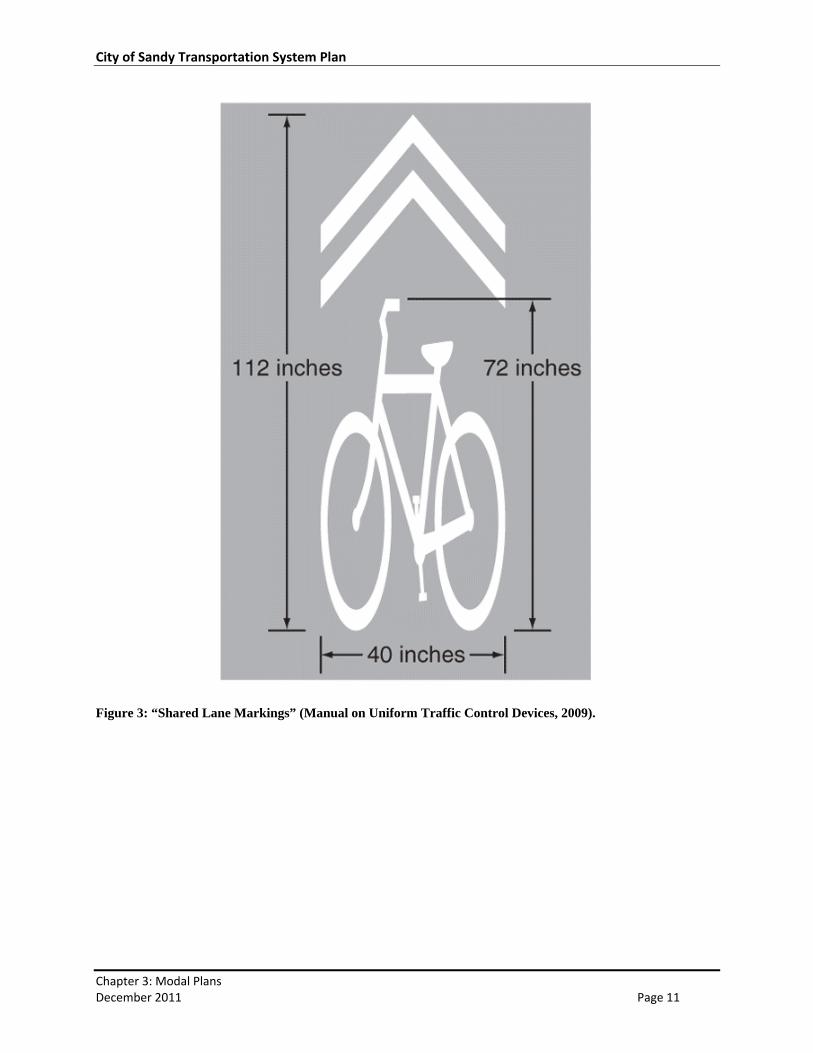
A further challenge to the implementation of bicycle lanes on Sandy’s streets is limited right‐of‐way and
adverse topography. In these situations, an alternative to widening the existing street or right‐of‐way or
reduction or elimination of parking along some sections of road could be to add “Shared Lane Markings”
as per the Manual on Uniform Traffic Control Devices, 2009 (MUTCD) which indicate to bicyclists and
motor vehicles that the lane shall be shared (Figure 3). In locations where it is only feasible to construct
bike lanes in one direction, priority should be given to at least providing bike lanes in the uphill direction
(where applicable) where the speed differential between motorists and bicyclists would be greater.
City of Sandy Transportation System Plan
Chapter 3: Modal Plans December 2011 Page 10
In addition to the projects listed in Table 2, the City of Sandy will take the following actions to further
encourage and enhance biking as a viable mode of travel.
A. The City will continue to require bicycle parking for multi‐family, retail, office, and institutional
developments per the Sandy Municipal Code (Section 17.98.20).
B. The City will work with the School District to improve the quality of bicycle parking facilities at
Sandy schools.
C. The City will seek opportunities to coordinate transit improvements with bicycle network
improvements that enhance the accessibility of transit stops.
D. The City will support the establishment of regional bicycle connections such as:
A linkage from Dubarko Road to Colorado Road over a series of connections to south
Boring and the Springwater Trail. This will eventually be replaced by a direct connection
to the Springwater trail from the proposed Tickle Creek Trail extension to the western
UGB.
A link to Estacada from Dubarko Road via Bornstedt Road and Wildcat Mountain Road.
City of Sandy Transportation System Plan
Chapter 3: Modal Plans December 2011 Page 11
Figure 3: “Shared Lane Markings” (Manual on Uniform Traffic Control Devices, 2009).
City of Sandy Transportation System Plan
Chapter 3: Modal Plans December 2011 Page 12
Table 2: Bicycle System Projects and Costs
Project ID* Project Segment Description
Project Cost (2009 Dollars)
City of Sandy Facility Bicycle Improvements
B1 362nd Dr. Dubarko Rd. to UGB Widen shoulder to 6’ $1,230,000
B2 Bluff Rd.** US 26 to Miller Rd. Re-stripe/widen Rd. $40,000
B3 Bornstedt Rd.** OR 211 to UGB Re-stripe/widen Rd. $32,000
B4 Dubarko Rd.** 362nd Dr. to Eldridge Dr. Re-stripe/widen Rd. $36,000
B5 Dubarko Rd.** Sandy Heights St. to Melissa Ave. Re-stripe/widen Rd. $36,000
B6 Langensand Rd.** US 26 to UGB Re-stripe/widen Rd. $61,200
B7 Meinig Ave.** Scenic St. to US 26 Re-stripe/widen Rd. $61,000
B8 Meinig Ave.** Barker Ct. to Dubarko Rd. Re-stripe/widen Rd. $17,000
B9 Sandy Heights St.** Bluff To End Re-stripe/widen Rd. $40,000
B10 Tupper Rd.** Long Circle to OR 211 Re-stripe/widen Rd. $59,000
ODOT Facility Bicycle Improvements
B11 OR 211 UGB to US 26 Widen shoulder to 6’ $28,200,000***
B12 US 26 Ten Eyck Rd. to UGB Widen shoulder to 6’ $3,260,000
Total Bicycle Projects $33,072,200
Notes: * Projects illustrated in Figure 3. **May require the elimination of on street parking (cost estimate for restripe only). ***Includes drainage, lighting, bicycle and pedestrian elements.
!!!!
!!
!
!
!!
!
!
!
!
!
!!!
!!
!
! !!
!!
!
!
!
!
!
!!
!
! ! !
!
! ! !
!
! ! !
!!
!
! !
!!
!
! !
!
!
!!
! !
!!
!
! !
!
!!
!!
!!
!!
!!
!!
!!
!!
!
!
!
!
! ! ! !
!!
!!
! !
!
!
! !
!!
!
!
!
!
!
!
!
! ! ! ! ! ! ! ! ! !
!!
!!
!!
!
!!
!
!
!
!
!
!
!
!!!!!
!!
!
!!
!
!!
!
!
!!
!!
!
!!!!!
!
!!!!
!!
!!
!!
!!
!!!!!!
!!
!!
!!
!
!
!
!
!!!
,
,
,
,
, ,,
,,,!
!!
!
k
!
!
!
!
!
!
!
!
!
!!
!
!
!
k
RUBEN LN
HWY
211
BLUFF R
D
ORIENT DR
362N
D D
R
TEN
EYC
K R
D
LAN
GEN
SAN
D R
D
211
BORN
STE
DT
RD
GUNDERSON RD
DUBAR KO RD
DUBARKO RD
VISTA LOOP
INDUSTRIAL WAY
BELL ST
JEW
LBER
RY
AVE
JAC
OBY
RD
VAN
FLE
ET
AVE
DAVI
S ST
PIONEER BLVD
PROCTOR BLVD
SANDY HEIGHTS ST
£¤26
£¤26
KELSO RD
MEI
NIG
AVE
TUPPER RD
SUNSET ST
TRUBEL RD
!
! !
!
!
!
!
!
!
!
!
!
!
!
!
!
!
!
!
!
!
Sandy River Park
City Hall Post Office
Tupper Park
Cascadia Park
Public LibraryCommunity Center
Sandy Skate Park
Sandy Bluff Park
Barlow Ridge Park
Jonsrud Viewpoint
Sandy High School
Bell Street Fields
Hamilton Ridge ParkMeinig Memorial Park
Timberline Trails Park
Sandy Elementary SchoolSalmon Creek Estates ParkCedar Ridge Middle School
Knollwood Park
B9
B8
B6
B4
B3
B2B1
B12
B11
B10B5
P4
P23
P21
P17
P22
P20
P19
P18
P16
±
City of SandyTRANSPORTATION SYSTEM PLAN
0 1,000500Feet
Figure 4Bicycle
System PlanExisting Facilities
Recommended Facility
*Note: May require reduction/removal of on-street parking.**Note: Multi-Use Trails are also shown on Figure 2.
Proposed Future Connection to the Springwater Trail
ParkUrban Reserve AreaUrban Growth BoundaryCity LimitsParcels
Future PathsRecommended Multi-Use Trail**Recommended Bicycle Facility*
Bike/Ped AccesswaysPaths
Activity Centers!
Traffic Signals,
Existing Designated Bicycle Lane/Shoulder
Project ID (See Tables 1 and 2)B1
rThese trails are identified in the Sandy River Park & Meinig Park Master Plans
Trails
City of Sandy Transportation System Plan
Chapter 3: Modal Plans December 2011 Page 14
Sandy Transit Master Plan Sandy Area Metro Transit (SAM) plays an important role in providing transportation within Sandy and as
a link in the regional multimodal transportation network. The connections to TriMet, Mountain Express,
and bicycle and pedestrian networks allow for an increased level of mobility for people in and around
Sandy, whether they are traveling to jobs, school, shopping, parks, or social and recreational events.
Sandy Transit services also help support a growing local economy, providing easy access to Sandy
businesses for both workers and shoppers.
An effective transit system places emphasis on providing mobility and independence for people who rely
on transit to meet their basic travel needs. Transit‐dependent individuals often include people with
disabilities, youth, elderly, and people with low‐incomes. Providing effective service ensures that transit‐
dependent and other individuals are able to get to the places they need to go. However, in order for
transit to effectively reduce automobile trips and the overall demand on the transportation system,
Sandy Transit must also provide a service that is an attractive alternative to driving.
The Sandy Transit Master Plan (TMP)1, completed in September 2009 and adopted by the City Council
on September 9, 2009 as Ordinance 2009‐02, represents the transit element of Sandy’s TSP. As with the
TSP, it is a long‐term community vision and blueprint for transit development in the City over the next
twenty years.
Motor Vehicle System Plan The Motor Vehicle System Plan provides direction for the management and expansion of the roadway
network to meet the City’s needs through the year 2029. The plan elements provide an array of
strategies to achieve local transportation goals by improving system capacity, efficiency, safety, and
connectivity. An analysis of the motor vehicle system under existing (2009) and future (2029) conditions,
as well as documentation of all alternatives considered, can be referenced in the appendices.
Transportation System Management Transportation System Management (TSM) focuses on low‐cost strategies to enhance the operational
performance of the transportation system by seeking solutions that better manage facilities and treat all
modes of travel as a coordinated system rather than relying on the construction of additional capacity
through new roadways. TSM strategies are often easier to implement because of the lower capital
investment required and they extend the functional life of existing and future facilities by optimizing
their ability to move traffic in a safe and efficient manner.
1 Sandy Transit Master Plan, CPH Planning, September 2009.
City of Sandy Transportation System Plan
Chapter 3: Modal Plans December 2011 Page 15
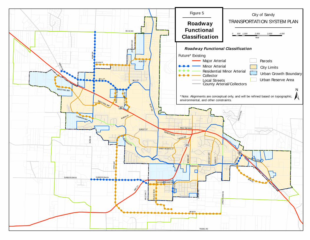
Roadway Functional Classification The functional classification system provides direction for the management and design of streets in the
City of Sandy. The roadway functional classification map is shown in Figure 4, with management
objectives and design criteria described below.
RUBEN LN
HWY
211
BLUFF RD
ORIENT DR
362N
D D
R
TEN
EYC
K R
D
LANG
ENSA
ND
RD
211
BOR
NST
EDT
RD
GUNDERSON RD
DUBARKO RD
DUBARKO RD
VISTA LOOP
INDUSTRIAL WAY
BELL ST
JEW
LBER
RY
AVE
JAC
OBY
RD
VAN
FLE
ET A
VE
DAVI
S ST
PIONEER BLVD
PROCTOR BLVD
SANDY HEIGHTS ST
£¤26
£¤26
KELSO RD
MEI
NIG
AVE
TUPPER RD
SUNSET ST
TRUBEL RD
!!!!
!!
!
!
!!
!
!
!
!
!
!!!
!!
!
! !!
!
!
!
!
!
!
!
!!
!
! ! !
!
! ! !
!
! ! !
!!
!
! !
!!
!
! !
!
!
!!
! !
!!
!
! !
!
!!
!!
!!
!!
!!
!!
!!
!!
!
!
!
!
! ! ! !
!!
!!
! !
!
!
! !
!!
!
!
!
!
!
!
!
! ! ! ! ! ! ! ! ! !
!!
!!
!!
!
!!
!
!
!
!
!
!
!
!
!!!!
!!
!
!!
!
!!
!
!
!!
!!
!
!!!!!
!
!!!!!
!!
!!
!!
!
!!!!!
!!
!
!!
!
!
!!!
!
!!!
!!!!!!
!
!!!!
!!
!!
!
!!
! ! !!
!!!!!
!!
!!
!!
!!
! ! ! !!
!!
!
!!
!!
!!
!!
!!
!!
!!
!!
!!
!!!
!!
! ! ! ! ! ! ! ! ! ! ! ! ! ! ! ! ! ! ! ! ! ! ! ! ! ! ! ! !
!!
!!
!!
! ! !
!! !
!!!
! ! ! ! !!!
!!
!
!!
!
!!
!!
!!
!
! !
!
!!!!! !!!!!!
!
!!!!
!!
!!
!
!!
! ! !!
!!!!!
!!
!!
!!
!!
! ! ! !!
!!
!
!!
!!
!!
!!
!!
!!
!!
!!
!!
!!!
!!
! ! ! ! ! ! ! ! ! ! ! ! ! ! ! ! ! ! ! ! ! ! ! ! ! ! ! ! !
!!
!!
!!
! ! !
!! !
!!!
! ! ! ! !
!!
!
!!
!!
!!
!
! !
!
!!!!!
! !!
!!
!! ! ! ! ! ! ! ! ! ! !
!!
!
! ! ! !
!!
!!
!!
!!
!!
!!
!!
!!
!!
!!
!!
!! !
!
!
! ! ! ! ! ! ! ! ! ! ! ! ! ! ! ! !!
!
!!
! !!
!!
!! ! ! ! ! ! ! ! ! ! !
!!
!
! ! ! !
!!
!!
!!
!!
!!
!!
!!
!!
!!
!!
!!
!! !
!
!
! ! ! ! ! ! ! ! ! ! ! ! ! ! ! ! !!
!
CHAMPION WAY
KATE
SC
HMIT
Z R
D
AGNES ST
NEW RD
VILL
AGE
BLVD
GUNDERSON RD
DUBA
RKO
RD
INDUSTRIAL WAY
BELL ST
362N
D D
R
370T
H A
VE
ARLE
THA
CT
IND
UST
RIAL
WAY
CASCADIA VILLAGE DR
NEW RD
OLSON ST
±
City of SandyTRANSPORTATION SYSTEM PLAN
0 1,000 2,000 3,000 4,000500Feet
Figure 5
RoadwayFunctional
ClassificationRoadway Functional Classification
Residential Minor ArterialCollector
Major ArterialMinor Arterial
Local StreetsCounty Arterial/Collectors
City LimitsUrban Growth Boundary
Parcels
Urban Reserve Area
Future* Existing
! ! !
! ! !
! ! !
*Note: Alignments are conceptual only, and will be refined based on topographic, environmental, and other constraints.
City of Sandy Transportation System Plan
Chapter 3: Modal Plans December 2011 Page 17
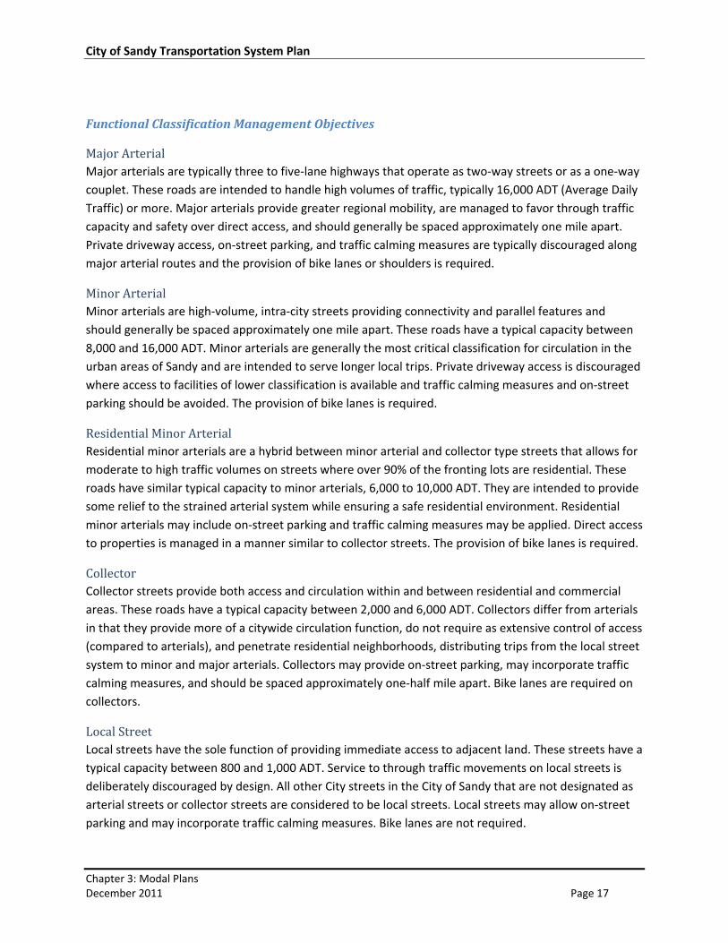
Functional Classification Management Objectives
Major Arterial Major arterials are typically three to five‐lane highways that operate as two‐way streets or as a one‐way
couplet. These roads are intended to handle high volumes of traffic, typically 16,000 ADT (Average Daily
Traffic) or more. Major arterials provide greater regional mobility, are managed to favor through traffic
capacity and safety over direct access, and should generally be spaced approximately one mile apart.
Private driveway access, on‐street parking, and traffic calming measures are typically discouraged along
major arterial routes and the provision of bike lanes or shoulders is required.
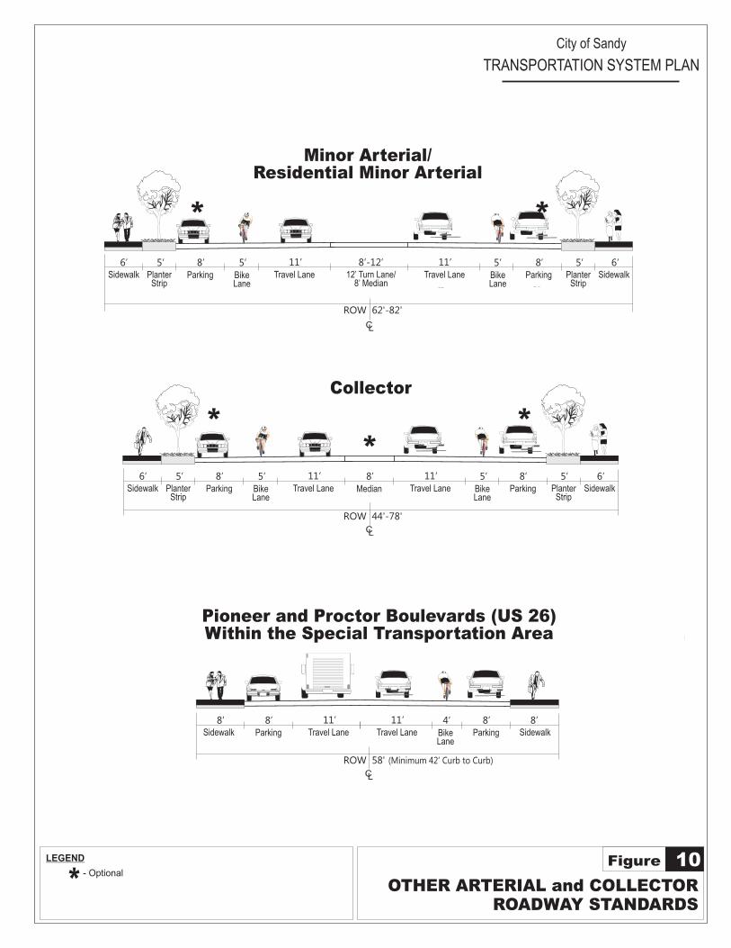
Minor Arterial Minor arterials are high‐volume, intra‐city streets providing connectivity and parallel features and
should generally be spaced approximately one mile apart. These roads have a typical capacity between
8,000 and 16,000 ADT. Minor arterials are generally the most critical classification for circulation in the
urban areas of Sandy and are intended to serve longer local trips. Private driveway access is discouraged
where access to facilities of lower classification is available and traffic calming measures and on‐street
parking should be avoided. The provision of bike lanes is required.
Residential Minor Arterial Residential minor arterials are a hybrid between minor arterial and collector type streets that allows for
moderate to high traffic volumes on streets where over 90% of the fronting lots are residential. These
roads have similar typical capacity to minor arterials, 6,000 to 10,000 ADT. They are intended to provide
some relief to the strained arterial system while ensuring a safe residential environment. Residential
minor arterials may include on‐street parking and traffic calming measures may be applied. Direct access
to properties is managed in a manner similar to collector streets. The provision of bike lanes is required.
Collector Collector streets provide both access and circulation within and between residential and commercial
areas. These roads have a typical capacity between 2,000 and 6,000 ADT. Collectors differ from arterials
in that they provide more of a citywide circulation function, do not require as extensive control of access
(compared to arterials), and penetrate residential neighborhoods, distributing trips from the local street
system to minor and major arterials. Collectors may provide on‐street parking, may incorporate traffic
calming measures, and should be spaced approximately one‐half mile apart. Bike lanes are required on
collectors.
Local Street Local streets have the sole function of providing immediate access to adjacent land. These streets have a
typical capacity between 800 and 1,000 ADT. Service to through traffic movements on local streets is
deliberately discouraged by design. All other City streets in the City of Sandy that are not designated as
arterial streets or collector streets are considered to be local streets. Local streets may allow on‐street
parking and may incorporate traffic calming measures. Bike lanes are not required.
City of Sandy Transportation System Plan
Chapter 3: Modal Plans December 2011 Page 18
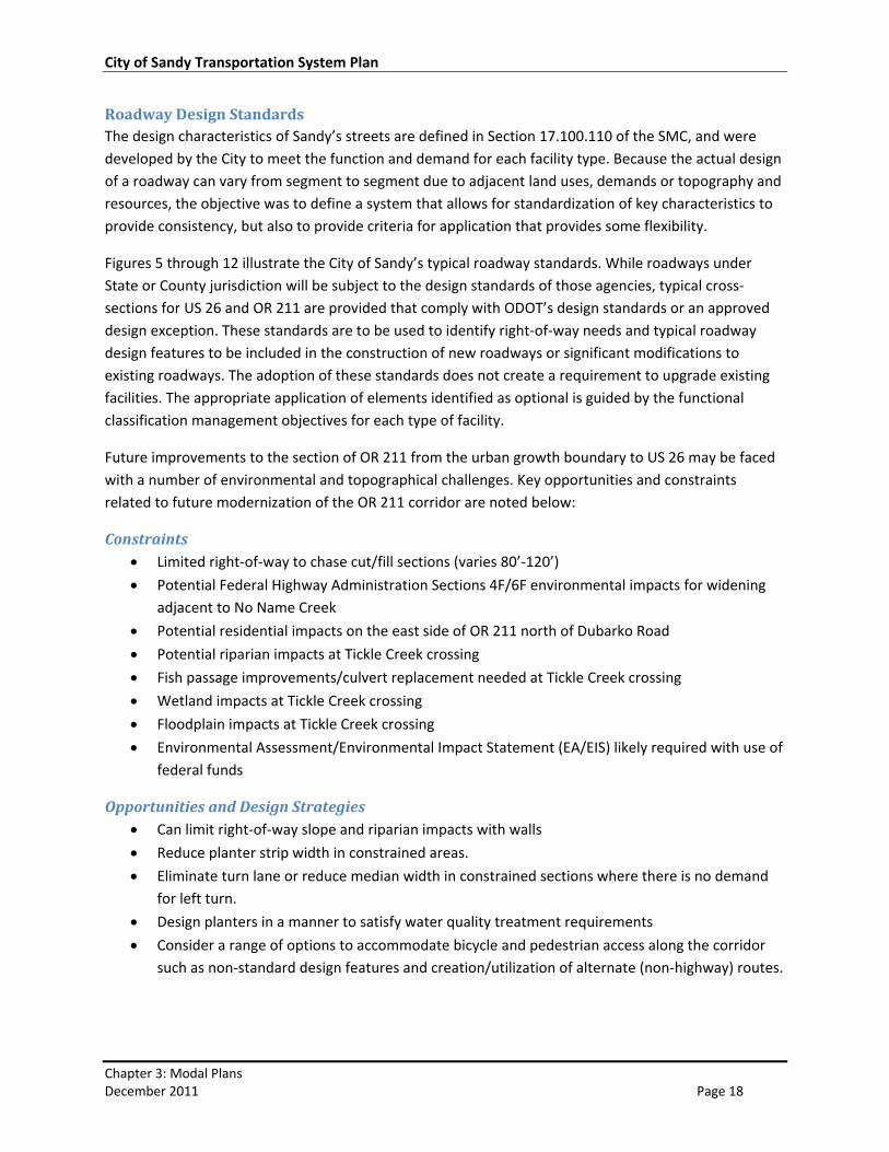
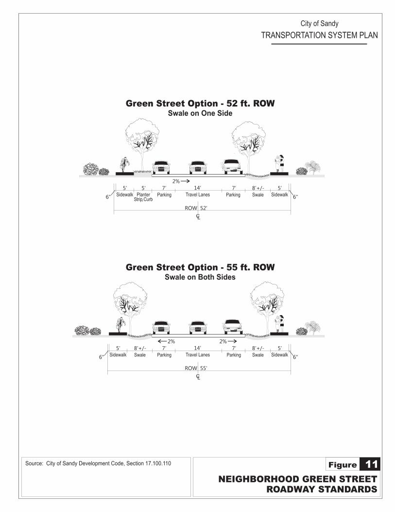
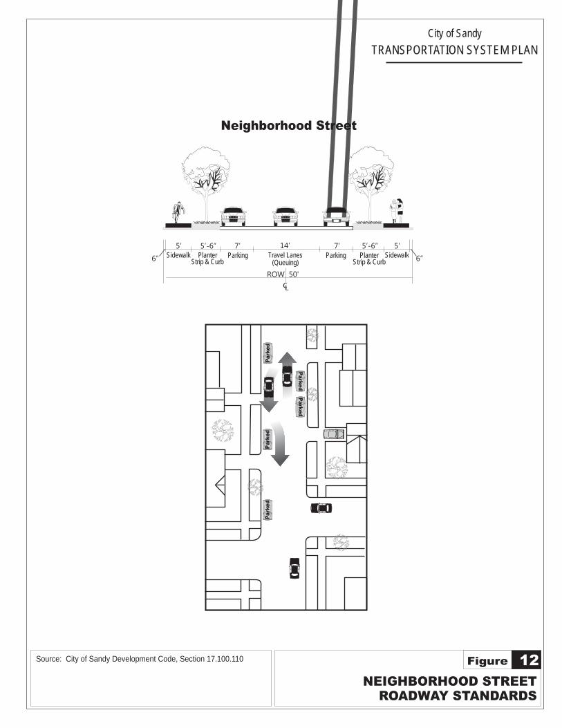
Roadway Design Standards The design characteristics of Sandy’s streets are defined in Section 17.100.110 of the SMC, and were
developed by the City to meet the function and demand for each facility type. Because the actual design
of a roadway can vary from segment to segment due to adjacent land uses, demands or topography and
resources, the objective was to define a system that allows for standardization of key characteristics to
provide consistency, but also to provide criteria for application that provides some flexibility.
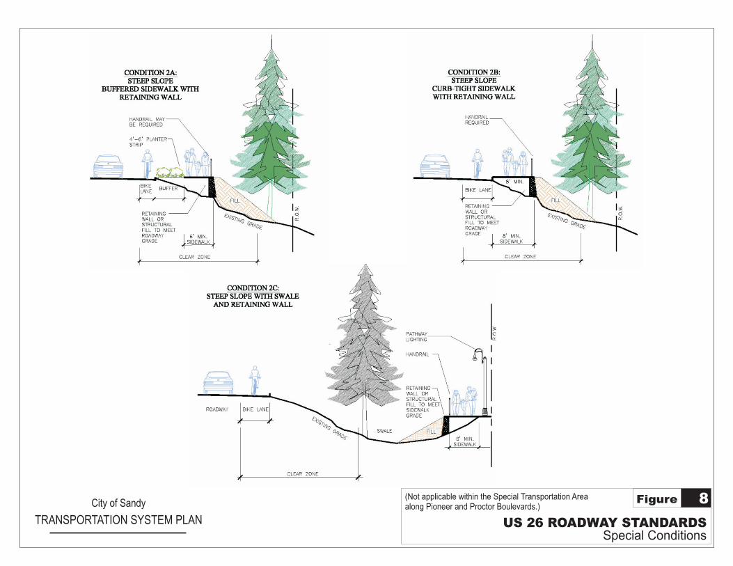
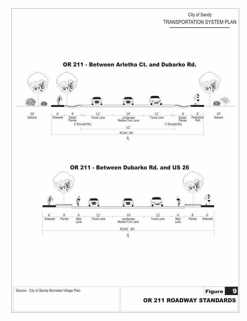
Figures 5 through 12 illustrate the City of Sandy’s typical roadway standards. While roadways under
State or County jurisdiction will be subject to the design standards of those agencies, typical cross‐
sections for US 26 and OR 211 are provided that comply with ODOT’s design standards or an approved
design exception. These standards are to be used to identify right‐of‐way needs and typical roadway
design features to be included in the construction of new roadways or significant modifications to
existing roadways. The adoption of these standards does not create a requirement to upgrade existing
facilities. The appropriate application of elements identified as optional is guided by the functional
classification management objectives for each type of facility.
Future improvements to the section of OR 211 from the urban growth boundary to US 26 may be faced
with a number of environmental and topographical challenges. Key opportunities and constraints
related to future modernization of the OR 211 corridor are noted below:
Constraints Limited right‐of‐way to chase cut/fill sections (varies 80’‐120’)
Potential Federal Highway Administration Sections 4F/6F environmental impacts for widening
adjacent to No Name Creek
Potential residential impacts on the east side of OR 211 north of Dubarko Road
Potential riparian impacts at Tickle Creek crossing
Fish passage improvements/culvert replacement needed at Tickle Creek crossing
Wetland impacts at Tickle Creek crossing
Floodplain impacts at Tickle Creek crossing
Environmental Assessment/Environmental Impact Statement (EA/EIS) likely required with use of
federal funds
Opportunities and Design Strategies Can limit right‐of‐way slope and riparian impacts with walls
Reduce planter strip width in constrained areas.
Eliminate turn lane or reduce median width in constrained sections where there is no demand
for left turn.
Design planters in a manner to satisfy water quality treatment requirements
Consider a range of options to accommodate bicycle and pedestrian access along the corridor
such as non‐standard design features and creation/utilization of alternate (non‐highway) routes.
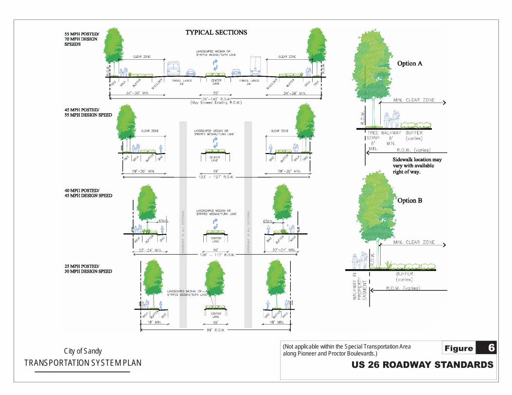
City of Sandy
TRANSPORTATION SYSTEM PLAN US 26 ROADWAY STANDARDS
6Figure (Not applicable within the Special Transportation Areaalong Pioneer and Proctor Boulevards.)
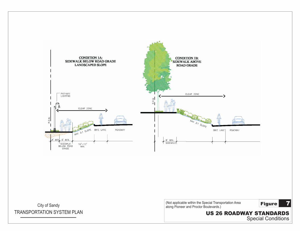
City of Sandy
TRANSPORTATION SYSTEM PLAN US 26 ROADWAY STANDARDSSpecial Conditions
7Figure (Not applicable within the Special Transportation Areaalong Pioneer and Proctor Boulevards.)
US 26 ROADWAY STANDARDSSpecial Conditions
8Figure City of Sandy
TRANSPORTATION SYSTEM PLAN
(Not applicable within the Special Transportation Areaalong Pioneer and Proctor Boulevards.)
Minor Residential Arterial allows on-street parking.
- On-street Parking Lane (except at intersections)
P
LEGEND
OR 211 ROADWAY STANDARDS
9Figure
City of Sandy
TRANSPORTATION SYSTEM PLAN
16’ 6’Sidewalk
12’8’Swale/Planter
Travel Lane
52'
1.
- Optional
CL
2. Traveling lane width is the bi-directional total(Queuing required for 14-17' lane widths).
Swale/Planter
6’Pedestrian
Path
OR 211 - Between Arletha Ct. and Dubarko Rd.
Travel Lanes
14’5’Sidewalk
7’Parking
ROW 55'
CL
6”
7’Parking
8’+/-Swale
5’Sidewalk 6”
2%
Green Street Option - 55 ft. ROWSwale on Both Sides
8’+/-Swale
2%
Source: City of Sandy Bornsted Village Plan
Travel Lanes
14’6’Sidewalk
7’5’Planter
Strip,C urbParking
ROW 52'
CL
7’Parking
8’+/-Swale
5’Sidewalk 6”
2%
Swale on One Side
Median/Turn LaneLandscape
12’Travel Lane
8’
ROW 80'
6’ Shoulder/Shy 6’ Shoulder/Shy
6’Sidewalk Planter
CL
ROW 80'
8’ 16’ 12’Travel Lane
12’Travel LaneBike
Lane
6’BikeLane
6’Planter
8’ 6’Sidewalk
Median/Turn LaneLandscape
Setback20’
Setback20’
OR 211 - Between Dubarko Rd. and US 26
Major Arterial
Minor Residential Arterial allows on-street parking.
- On-street Parking Lane (except at intersections)
P
LEGEND
OTHER ARTERIAL and COLLECTORROADWAY STANDARDS
10Figure
Travel Lane Travel Lane
City of Sandy
TRANSPORTATION SYSTEM PLAN
Two-Way Left Turn Lane/
Landscape Median
14’ 11’Travel Lane
11’Travel Lane
11’ 11’8.5’BikeLane
PlanterStrip
6.5’Sidewalk
Minor Arterial/Residential Minor Arterial
8’-12’Travel Lane
11’ 6’Travel Lane
11’Sidewalk
6’Sidewalk
8’
7’BikeLane
7’ 6.5’Sidewalk
5’PlanterStrip
Parking
5’BikeLane
5’BikeLane
5’Planter
Strip
Collector
Travel Lane
11’Travel Lane
11’Sidewalk
6’Sidewalk
8’5’Planter
StripParking
5’BikeLane
5’BikeLane
PlanterStrip
8’Parking
8.5’PlanterStrip
ROW 80'-102'
12’ Turn Lane/8’ Median
ROW 62'-82'
1.
- Optional
8’Median
ROW 44'-78'
Local
Sidewalk5.5’
Sidewalk7’5.5’
PlanterStrip
On-StreetParking
5.5’PlanterStrip
7’On-StreetParking
5.5’
ROW 50'
Travel Lane14’
Travel Lane14’
CL
CL
CL
CL
2.
2. Traveling lane width is the bi-directional total(Queuing required for 14-17' lane widths).
8’Parking
5’ 6’
Pioneer and Proctor Boulevards (US 26)Within the Special Transportation Area
Travel Lane
11’Travel Lane
11’Sidewalk
8’Sidewalk
8’Parking
4’BikeLane
8’Parking
ROW 58'
CL
8’
(Minimum 42’ Curb to Curb)
Minor Residential Arterial allows on-street parking.
- On-street Parking Lane (except at intersections)
P
LEGEND
NEIGHBORHOOD GREEN STREETROADWAY STANDARDS
11Figure
City of Sandy
TRANSPORTATION SYSTEM PLAN
Travel Lanes
14’5’Sidewalk
7’5’Planter
Strip,C urbParking
ROW 52'
1.
- Optional
CL
2. Traveling lane width is the bi-directional total(Queuing required for 14-17' lane widths).
6”
7’Parking
8’+/-Swale
5’Sidewalk 6”
2%
Green Street Option - 52 ft. ROWSwale on One Side
Travel Lanes
14’5’Sidewalk
7’Parking
ROW 55'
CL
6”
7’Parking
8’+/-Swale
5’Sidewalk 6”
2%
Green Street Option - 55 ft. ROWSwale on Both Sides
8’+/-Swale
2%
Source: City of Sandy Development Code, Section 17.100.110
Minor Residential Arterial allows on-street parking.
- On-street Parking Lane (except at intersections)
P
LEGEND
NEIGHBORHOOD STREETROADWAY STANDARDS
12Figure
City of Sandy
TRANSPORTATION SYSTEM PLAN
Travel Lanes(Queuing)
14’5’Sidewalk
7’5’-6”Planter
Strip & C urbParking
ROW 50'
1.
- Optional
CL
2. Traveling lane width is the bi-directional total(Queuing required for 14-17' lane widths).
6”
7’Parking
5’-6”Planter
Strip & Curb
5’Sidewalk 6”
Neighborhood Street
Travel Lanes
14’5’Sidewalk
7’Parking
ROW 55'
CL
6”
7’Parking
8’+/-Swale
5’Sidewalk 6”
2%
Green Street Option - 55 ft. ROWSwale on Both Sides
8’+/-Swale
2%
Source: City of Sandy Development Code, Section 17.100.110
Park
ed
Park
ed
Park
ed
Park
ed
Park
ed
Minor Residential Arterial allows on-street parking.
- On-street Parking Lane (except at intersections)
P
LEGEND
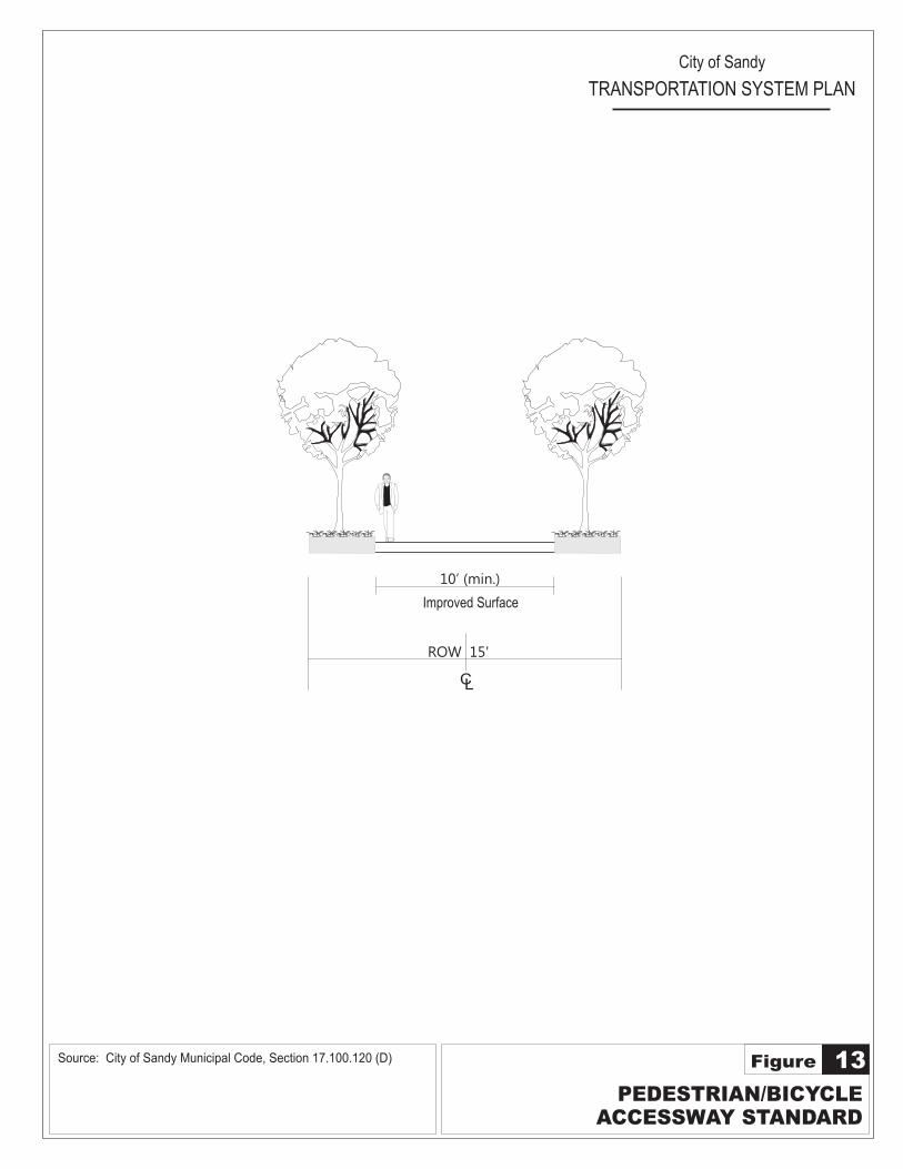
PEDESTRIAN/BICYCLEACCESSWAY STANDARD
13Figure
City of Sandy
TRANSPORTATION SYSTEM PLAN
Improved Surface
10’ (min.)
ROW 15'
1.
- Optional
CL
2. Traveling lane width is the bi-directional total(Queuing required for 14-17' lane widths).
Travel Lanes
14’5’Sidewalk
7’Parking
ROW 55'
CL
6”
7’Parking
8’+/-Swale
5’Sidewalk 6”
2%
Green Street Option - 55 ft. ROWSwale on Both Sides
8’+/-Swale
2%
Source: City of Sandy Municipal Code, Section 17.100.120 (D)
City of Sandy Transportation System Plan
Chapter 3: Modal Plans December 2011 Page 27
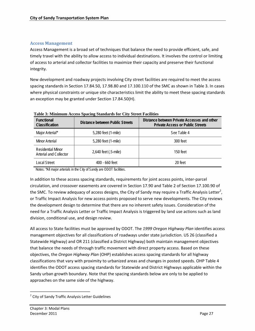
Access Management Access Management is a broad set of techniques that balance the need to provide efficient, safe, and
timely travel with the ability to allow access to individual destinations. It involves the control or limiting
of access to arterial and collector facilities to maximize their capacity and preserve their functional
integrity.
New development and roadway projects involving City street facilities are required to meet the access
spacing standards in Section 17.84.50, 17.98.80 and 17.100.110 of the SMC as shown in Table 3. In cases
where physical constraints or unique site characteristics limit the ability to meet these spacing standards
an exception may be granted under Section 17.84.50(H).
Table 3: Minimum Access Spacing Standards for City Street Facilities
Functional Classification
Distance between Public Streets Distance between Private Accesses and other Private Access or Public Streets
Major Arterial* 5,280 feet (1-mile) See Table 4
Minor Arterial 5,280 feet (1-mile) 300 feet
Residential Minor Arterial and Collector 2,640 feet (.5-mile) 150 feet
Local Street 400 - 660 feet 20 feet
Notes: *All major arterials in the City of Sandy are ODOT facilities.
In addition to these access spacing standards, requirements for joint access points, inter‐parcel
circulation, and crossover easements are covered in Section 17.90 and Table 2 of Section 17.100.90 of
the SMC. To review adequacy of access designs, the City of Sandy may require a Traffic Analysis Letter2,
or Traffic Impact Analysis for new access points proposed to serve new developments. The City reviews
the development design to determine that there are no inherent safety issues. Consideration of the
need for a Traffic Analysis Letter or Traffic Impact Analysis is triggered by land use actions such as land
division, conditional use, and design review.
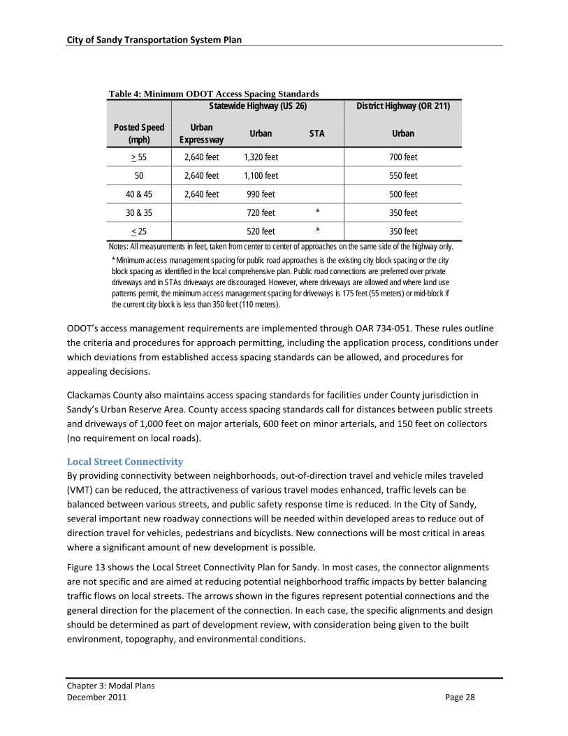
All access to State facilities must be approved by ODOT. The 1999 Oregon Highway Plan identifies access
management objectives for all classifications of roadways under state jurisdiction. US 26 (classified a
Statewide Highway) and OR 211 (classified a District Highway) both maintain management objectives
that balance the needs of through traffic movement with direct property access. Based on these
objectives, the Oregon Highway Plan (OHP) establishes access spacing standards for all highway
classifications that vary with proximity to urbanized areas and changes in posted speeds. OHP Table 4
identifies the ODOT access spacing standards for Statewide and District Highways applicable within the
Sandy urban growth boundary. Note that the spacing standards below are only to be applied to
approaches on the same side of the highway.
2 City of Sandy Traffic Analysis Letter Guidelines
City of Sandy Transportation System Plan
Chapter 3: Modal Plans December 2011 Page 28
Table 4: Minimum ODOT Access Spacing Standards Statewide Highway (US 26) District Highway (OR 211)
Posted Speed (mph)
Urban Expressway
Urban STA Urban
> 55 2,640 feet 1,320 feet 700 feet
50 2,640 feet 1,100 feet 550 feet
40 & 45 2,640 feet 990 feet 500 feet
30 & 35 720 feet * 350 feet
< 25 520 feet * 350 feet
Notes: All measurements in feet, taken from center to center of approaches on the same side of the highway only.
* Minimum access management spacing for public road approaches is the existing city block spacing or the city block spacing as identified in the local comprehensive plan. Public road connections are preferred over private driveways and in STAs driveways are discouraged. However, where driveways are allowed and where land use patterns permit, the minimum access management spacing for driveways is 175 feet (55 meters) or mid-block if the current city block is less than 350 feet (110 meters).
ODOT’s access management requirements are implemented through OAR 734‐051. These rules outline
the criteria and procedures for approach permitting, including the application process, conditions under
which deviations from established access spacing standards can be allowed, and procedures for
appealing decisions.
Clackamas County also maintains access spacing standards for facilities under County jurisdiction in
Sandy’s Urban Reserve Area. County access spacing standards call for distances between public streets
and driveways of 1,000 feet on major arterials, 600 feet on minor arterials, and 150 feet on collectors
(no requirement on local roads).
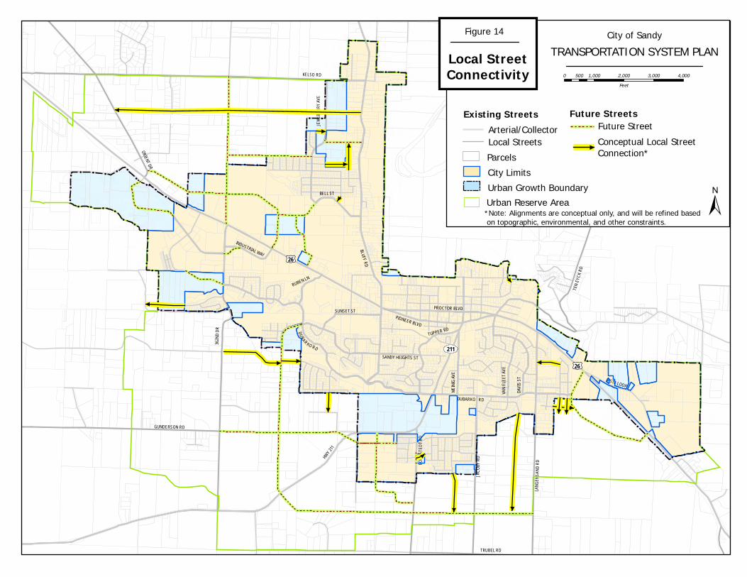
Local Street Connectivity By providing connectivity between neighborhoods, out‐of‐direction travel and vehicle miles traveled
(VMT) can be reduced, the attractiveness of various travel modes enhanced, traffic levels can be
balanced between various streets, and public safety response time is reduced. In the City of Sandy,
several important new roadway connections will be needed within developed areas to reduce out of
direction travel for vehicles, pedestrians and bicyclists. New connections will be most critical in areas
where a significant amount of new development is possible.
Figure 13 shows the Local Street Connectivity Plan for Sandy. In most cases, the connector alignments
are not specific and are aimed at reducing potential neighborhood traffic impacts by better balancing
traffic flows on local streets. The arrows shown in the figures represent potential connections and the
general direction for the placement of the connection. In each case, the specific alignments and design
should be determined as part of development review, with consideration being given to the built
environment, topography, and environmental conditions.
RUBEN LN
HWY
211
BLUFF RD
ORIENT DR
362N
D D
R
TEN
EYC
K R
D
LANG
ENSA
ND
RD
211
BOR
NST
EDT
RD
GUNDERSON RD
DUBARKO RD
DUBARKO RD
VISTA LOOP
INDUSTRIAL WAY
BELL ST
JEW
LBER
RY
AVE
JAC
OBY
RD
VAN
FLE
ET A
VE
DAVI
S ST
PIONEER BLVD
PROCTOR BLVD
SANDY HEIGHTS ST
£¤26
£¤26
KELSO RD
MEI
NIG
AVE
TUPPER RD
SUNSET ST
TRUBEL RD
!!!!
!!
!
!
!!
!
!
!
!
!
!!!
!!
!
! !!
!
!
!
!
!
!
!
!!
!
! ! !
!
! ! !
!
! ! !
!!
!
! !
!!
!
! !
!
!
!!
! !
!!
!
! !
!
!!
!!
!!
!!
!!
!!
!!
!!
!
!
!
!
! ! ! !
!!
!!
! !
!
!
! !
!!
!
!
!
!
!
!
!
! ! ! ! ! ! ! ! ! !
!!
!!
!!
!
!!
!
!
!
!
!
!
!
!
!!!!
!!
!
!!
!
!!
!
!
!!
!!
!
!!!!!
!
!!!!!
!!
!!
!!
!
!!!!!
!!
!
!!
!
!
!!!
!
!!!
±
City of SandyTRANSPORTATION SYSTEM PLAN
0 1,000 2,000 3,000 4,000500Feet
Figure 14
Local StreetConnectivity
Arterial/CollectorLocal Streets
City LimitsUrban Growth Boundary
Parcels
Urban Reserve Area
Existing Streets
Conceptual Local Street Connection*
Future Street
*Note: Alignments are conceptual only, and will be refined based on topographic, environmental, and other constraints.
Future Streets
City of Sandy Transportation System Plan
Chapter 3: Modal Plans December 2011 Page 30
Should new cul‐de‐sacs be created, bicycle and pedestrian accessways to provide a connection to the
surrounding transportation system from the cul‐de‐sac shall be required per Section 17.100.120(D) of
the SMC.
To protect existing neighborhoods from the potential traffic impacts caused by extending stub end
streets, the City may require appropriate traffic calming measures be incorporated into the design and
construction of new street extensions. In addition, when a development constructs stub streets, the
City may require the installation of signs indicating the potential for future connectivity to increase
residents’ awareness. Additionally, new developments that construct new streets or street extensions
are required by Section 17.100.100(F) of the SMC to provide a proposed street map that:
Provides full street connections with spacing of no more than 400 feet between connections
except where prevented by barriers or access management standards on higher classified
facilities
Provides bike and pedestrian accessways through the middle of the block when block lengths
exceed 600 feet
Limits use of cul‐de‐sacs and other closed‐end street systems to situations where existing
barriers prevent full street connections
Includes no cul‐de‐sacs or close‐end street longer than 400 feet. Those longer than 400 feet, or
developments with only one access point, may be required to provide an alternative access for
emergency vehicle use only
Includes street cross‐sections showing dimensions of right‐of‐way improvements, with streets
designed for posted or expected speed limits which meet City design standards (or ODOT
standards for state highways)
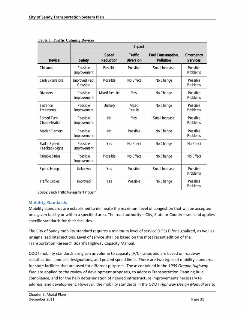
Neighborhood Traffic Management Neighborhood Traffic Management (NTM) strategies are commonly used to slow down or reduce
automotive traffic with the intent of improving safety for pedestrians and bicyclists. Such strategies are
not suited for arterial and collector streets, including US 26 and OR 211. However, NTM strategies can
be applied to local streets. Sandy has a NTM program that outlines the process for identifying,
prioritizing, and mitigating problems related to traffic speeds and volumes on local streets.
To initiate the Sandy Neighborhood Traffic Management Program process, a citizen request
accompanied by a petition with signatures of at least 50% of the residents in the project area must be
submitted to the City. Each request will be evaluated, and those that pass this process will be reviewed
for a range of possible traffic calming device (Table 5) solutions.
City of Sandy Transportation System Plan
Chapter 3: Modal Plans December 2011 Page 31
Table 5: Traffic Calming Devices
Device
Impact
Safety Speed
Reduction Traffic
Diversion Fuel Consumption,
Pollution Emergency
Services
Chicanes Possible Improvement
Possible Possible Small Increase Possible Problems
Curb Extensions Improved Ped. Crossing
Possible No Effect No Change Possible Problems
Diverters Possible Improvement
Mixed Results Yes No Change Possible Problems
Entrance Treatments
Possible Improvement
Unlikely Mixed Results
No Change Possible Problems
Forced Turn Channelization
Possible Improvement
No Yes Small Increase Possible Problems
Median Barriers Possible Improvement
No Possible No Change Possible Problems
Radar Speed Feedback Signs
Possible Improvement
Yes No Effect No Change No Effect
Rumble Strips Possible Improvement
Possible No Effect No Change No Effect
Speed Humps Unknown Yes Possible Small Increase Possible Problems
Traffic Circles Improved Yes Possible No Change Possible Problems
Source: Sandy Traffic Management Program
Mobility Standards Mobility standards are established to delineate the maximum level of congestion that will be accepted
on a given facility or within a specified area. The road authority – City, State or County – sets and applies
specific standards for their facilities.
The City of Sandy mobility standard requires a minimum level of service (LOS) D for signalized, as well as
unsignalized intersections. Level of service shall be based on the most recent edition of the
Transportation Research Board’s Highway Capacity Manual.
ODOT mobility standards are given as volume to capacity (V/C) ratios and are based on roadway
classification, land use designations, and posted speed limits. There are two types of mobility standards
for state facilities that are used for different purposes. Those contained in the 1999 Oregon Highway
Plan are applied to the review of development proposals, to address Transportation Planning Rule
compliance, and for the help determination of needed infrastructure improvements necessary to
address land development. However, the mobility standards in the ODOT Highway Design Manual are to
City of Sandy Transportation System Plan
Chapter 3: Modal Plans December 2011 Page 32
be applied to the evaluation of all alternatives considered for roadway improvements through public
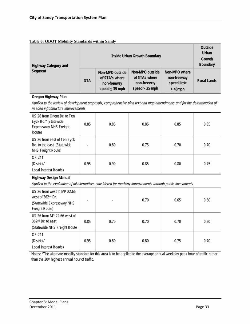
investments. ODOT mobility standards applicable within the City of Sandy are shown in Table 6.
Through the process of updating the City of Sandy’s TSP, it was found that, even with full build‐out of
the recommended transportation system, ODOT’s mobility standards for US 26 could not be met. In
response, ODOT and the City have worked together to develop alternate mobility standards for US 26 in
the Orient Drive to Ten Eyck Road section. These alternate mobility standards shall be adopted in the
Sandy TSP, but will not be in force until ODOT, through action by the Oregon Transportation
Commission, adopts the alternate mobility standards in an amendment to the 1999 Oregon Highway
Plan.
The new mobility standards are to be applied to the average annual weekday peak hour of traffic rather
than the 30th highest annual hour of traffic, and will allow volume to capacity ratios as high as 0.85.
At unsignalized intersections and road approaches, the volume to capacity ratios shall not be exceeded
for either of the state highway approaches that are not stopped. Approaches at which traffic must stop,
or otherwise yield the right of way, shall be operated to maintain safe operation of the intersection and
all of its approaches and shall not exceed the volume capacity ratios for District/Local Interest Roads in
Table 6 within the urban growth boundary.
City of Sandy Transportation System Plan
Chapter 3: Modal Plans December 2011 Page 33
Table 6: ODOT Mobility Standards within Sandy
Highway Category and Segment
Inside Urban Growth Boundary
Outside Urban
Growth Boundary
STA
Non-MPO outside of STA’s where
non-freeway speed < 35 mph
Non-MPO outside of STAs where non-freeway
speed > 35 mph
Non-MPO where non-freeway speed limit
> 45mph
Rural Lands
Oregon Highway Plan
Applied to the review of development proposals, comprehensive plan text and map amendments and for the determination of needed infrastructure improvements
US 26 from Orient Dr. to Ten Eyck Rd.* (Statewide Expressway NHS Freight Route)
0.85 0.85 0.85 0.85 0.85
US 26 from east of Ten Eyck Rd. to the east (Statewide NHS Freight Route)
- 0.80 0.75 0.70 0.70
OR 211
(District/
Local Interest Roads)
0.95 0.90 0.85 0.80 0.75
Highway Design Manual
Applied to the evaluation of all alternatives considered for roadway improvements through public investments
US 26 from west to MP 22.66 west of 362nd Dr.
(Statewide Expressway NHS Freight Route)
- - 0.70 0.65 0.60
US 26 from MP 22.66 west of 362nd Dr. to east
(Statewide NHS Freight Route 0.85 0.70 0.70 0.70 0.60
OR 211
(District/
Local Interest Roads)
0.95 0.80 0.80 0.75 0.70
Notes: *The alternate mobility standard for this area is to be applied to the average annual weekday peak hour of traffic rather than the 30th highest annual hour of traffic.
City of Sandy Transportation System Plan
Chapter 3: Modal Plans December 2011 Page 34
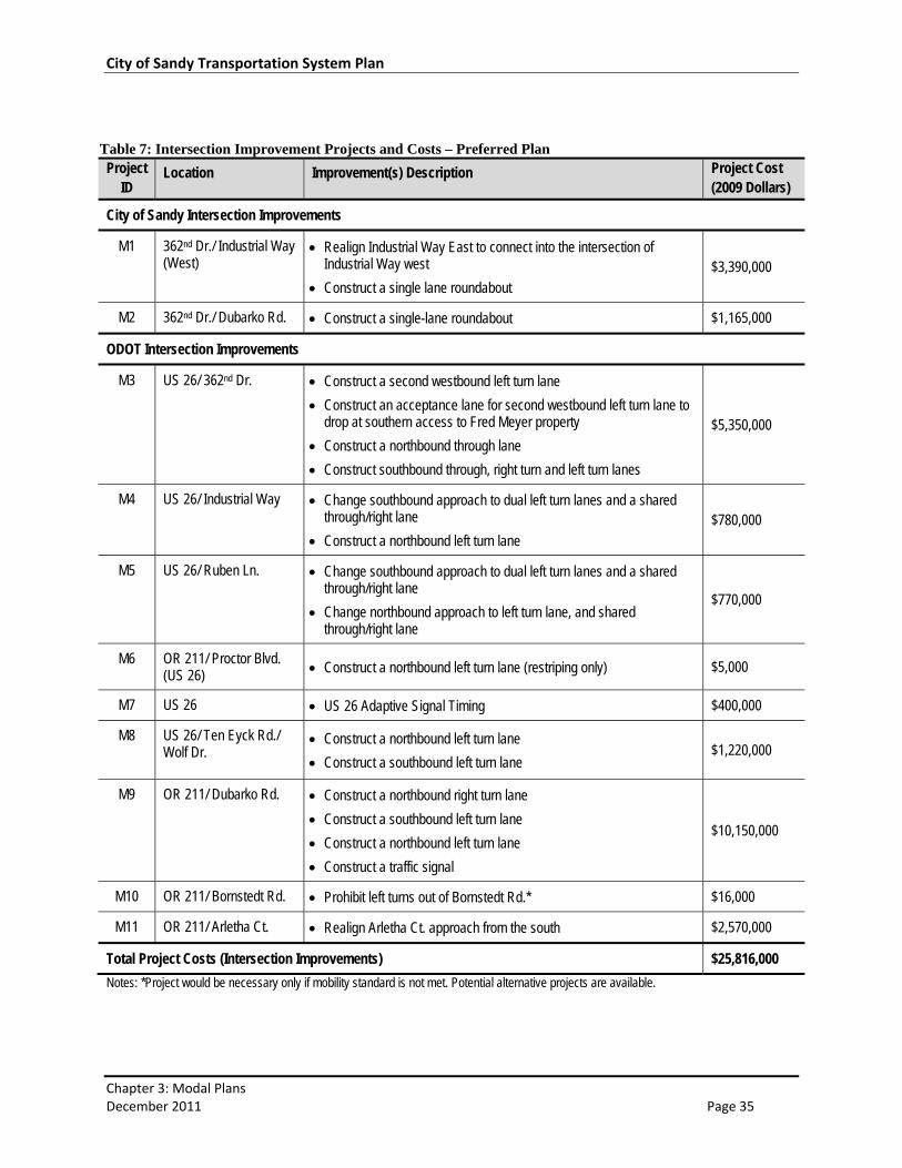
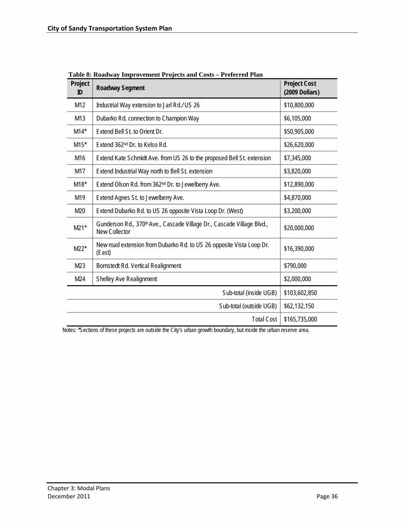
Motor Vehicle System Projects The motor vehicle system projects were developed to address existing and long‐range needs for
network capacity and safety. These projects, listed in Tables 7 and 8 and shown in Figure 14, represent
the motor vehicle component of the “Preferred Plan”, which consists of all transportation improvements
identified to support growth through the year 2029. Projects assumed for “Near Term” implementation,
which represent a subset of the Preferred Plan that aligns with anticipated funding, are listed in Chapter
4.
Operations at key roadway network intersections in the City were analyzed under future (year 2029)
conditions with and without the Preferred Plan motor vehicle system projects in place. The results are
provided in Table 9. As shown, all intersections under City jurisdiction will operate within adopted
mobility standards with the Preferred Plan improvements in place. On the state highways, the
recommended improvement projects coupled with the adoption of alternate mobility standards from
Orient Drive to Ten Eyck Road will be essential for accommodating future growth. While this will
mitigate intersection operations in most areas, the unsignalized intersections on US 26 east of the
downtown (at Langensand Road, Vista Loop Drive West, and Vista Loop Drive East) are still projected to
fail to meet mobility standards in the future.
At these locations, minor street delays can be long due to the conflict with high highway traffic volumes.
However, the forecasted demand for the minor street movements remains too low to warrant the
installation of traffic signals at any one intersection. This low demand results in part from the fact that
most trips are oriented to and from the west and that there are other roadways available to serve that
demand. Because the attractiveness of alternate routes to and from the west will be affected by the
recommended improvement projects in this plan, the actual demand experienced at the US 26
intersections east of the downtown could be influenced by the timing of those improvements relative to
development growth. Therefore, continued monitoring of operations and safety at these intersections
as growth occurs is recommended.
City of Sandy Transportation System Plan
Chapter 3: Modal Plans December 2011 Page 35
Table 7: Intersection Improvement Projects and Costs – Preferred Plan Project
ID Location Improvement(s) Description Project Cost
(2009 Dollars)
City of Sandy Intersection Improvements
M1 362nd Dr./ Industrial Way (West)
Realign Industrial Way East to connect into the intersection of Industrial Way west
Construct a single lane roundabout $3,390,000
M2 362nd Dr./ Dubarko Rd. Construct a single-lane roundabout $1,165,000
ODOT Intersection Improvements
M3 US 26/ 362nd Dr. Construct a second westbound left turn lane
Construct an acceptance lane for second westbound left turn lane to drop at southern access to Fred Meyer property
Construct a northbound through lane
Construct southbound through, right turn and left turn lanes
$5,350,000
M4 US 26/ Industrial Way Change southbound approach to dual left turn lanes and a shared through/right lane
Construct a northbound left turn lane $780,000
M5 US 26/ Ruben Ln. Change southbound approach to dual left turn lanes and a shared through/right lane
Change northbound approach to left turn lane, and shared through/right lane
$770,000
M6 OR 211/ Proctor Blvd. (US 26) Construct a northbound left turn lane (restriping only) $5,000
M7 US 26 US 26 Adaptive Signal Timing $400,000
M8 US 26/ Ten Eyck Rd./ Wolf Dr.
Construct a northbound left turn lane
Construct a southbound left turn lane $1,220,000
M9 OR 211/ Dubarko Rd. Construct a northbound right turn lane
Construct a southbound left turn lane
Construct a northbound left turn lane
Construct a traffic signal
$10,150,000
M10 OR 211/ Bornstedt Rd. Prohibit left turns out of Bornstedt Rd.* $16,000
M11 OR 211/ Arletha Ct. Realign Arletha Ct. approach from the south $2,570,000
Total Project Costs (Intersection Improvements) $25,816,000
Notes: *Project would be necessary only if mobility standard is not met. Potential alternative projects are available.
City of Sandy Transportation System Plan
Chapter 3: Modal Plans December 2011 Page 36
Table 8: Roadway Improvement Projects and Costs – Preferred Plan Project
ID Roadway Segment
Project Cost (2009 Dollars)
M12 Industrial Way extension to Jarl Rd./ US 26 $10,800,000
M13 Dubarko Rd. connection to Champion Way $6,105,000
M14* Extend Bell St. to Orient Dr. $50,905,000
M15* Extend 362nd Dr. to Kelso Rd. $26,620,000
M16 Extend Kate Schmidt Ave. from US 26 to the proposed Bell St. extension $7,345,000
M17 Extend Industrial Way north to Bell St. extension $3,820,000
M18* Extend Olson Rd. from 362nd Dr. to Jewelberry Ave. $12,890,000
M19 Extend Agnes St. to Jewelberry Ave. $4,870,000
M20 Extend Dubarko Rd. to US 26 opposite Vista Loop Dr. (West) $3,200,000
M21* Gunderson Rd., 370th Ave., Cascade Village Dr., Cascade Village Blvd., New Collector $20,000,000
M22* New road extension from Dubarko Rd. to US 26 opposite Vista Loop Dr. (East) $16,390,000
M23 Bornstedt Rd. Vertical Realignment $790,000
M24 Shelley Ave Realignment $2,000,000
Sub-total (inside UGB) $103,602,850
Sub-total (outside UGB) $62,132,150
Total Cost $165,735,000
Notes: *Sections of these projects are outside the City’s urban growth boundary, but inside the urban reserve area.
RUBEN LN
HWY
211
BLUFF R
D
ORIENT DR
362N
D D
R
TEN
EYC
K R
D
LAN
GEN
SAN
D R
D
211
BORN
STE
DT
RD
GUNDERSON RD
DUBAR KO RD
DUBARKO RD
VISTA LOOP
INDUSTRIAL WAY
BELL ST
JEW
LBER
RY
AVE
JAC
OBY
RD
VAN
FLE
ET A
VE
DAVI
S ST
PIONEER BLVD
PROCTOR BLVD
SANDY HEIGHTS ST
£¤26
£¤26
KELSO RD
MEI
NIG
AVE
TUPPER RD
SUNSET ST
TRUBEL RD
!!!!
!!
!
!
!!
!
!
!
!
!
!!!
!!
!
! !!
!
!
!
!
!
!
!
!!
!
! ! !
!
! ! !
!
! ! !
!!
!
! !
!!
!
! !
!
!
!!
! !
!!
!
! !
!
!!
!!
!!
!!
!!
!!
!!
!!
!
!
!
!
! ! ! !
!!
!
!! !
!
!
! !
!!
!
!
!
!
!
!
!
! ! ! ! ! ! ! ! ! !
!!
!!
!!
!
!!
!
!
!
!
!
!
!
!!!!!
!!
!
!!
!
!!
!
!
!!
!!
!
!!!!!
!
!!!!!!
!!
!!
!!
!!!!!!
!!
!!
!!
!
!
!
!
!!!
!!!!!!!
!
!!!!!
!!
!!
!
!!
! ! !!
!!!!!!
!!
!!
!!
!!
!! ! ! !
!
!!!
!!
!!
!!
!!
!!
!!
!!
!!
!!
!!
!!!!!!
! ! ! ! ! ! ! ! ! ! ! ! ! ! ! ! ! ! ! ! ! ! ! ! ! ! ! ! ! ! !
!!
!!
!!
!
! ! !
!! !
!!!
! ! !! ! !!!
!!
!!
!
! !
!
!!!!!! !!!!!!!
!
!!!!!
!!
!!
!
!!
! ! !!
!!!!!!
!!
!!
!!
!!
!! ! ! !
!
!!!
!!
!!
!!
!!
!!
!!
!!
!!
!!
!!
!!!!!!
! ! ! ! ! ! ! ! ! ! ! ! ! ! ! ! ! ! ! ! ! ! ! ! ! ! ! ! ! ! !
!!
!!
!!
!
! ! !
!! !
!!!
! ! !! ! !
!!
!!
!
! !
!
!!!!!!
!!
!
!!
!!!
!!
!
!!
! !!
!!
!! ! ! ! ! ! ! ! ! ! !
!!
!
! ! ! !
!!
!!
!!
!!
!!
!!
!!
!!
!!
!!
!!
!! !
!
!
! ! ! ! ! ! ! ! ! ! ! ! ! ! ! ! !!
!
!!
! !!
!!
!! ! ! ! ! ! ! ! ! ! !
!!
!
! ! ! !
!!
!!
!!
!!
!!
!!
!!
!!
!!
!!
!!
!! !
!
!
! ! ! ! ! ! ! ! ! ! ! ! ! ! ! ! !!
!
CHAMPION WAY
KATE
SC
HM
ITZ
RD
AGNES ST
NEW RD
VILL
AGE
BLV
D
GUNDERSON RD
DUBA
RKO
RD
INDUSTRIAL WAY
BELL ST
362N
D D
R
370T
H A
VE
ARLE
THA
CT
IND
UST
RIA
L W
AY
CASCADIA VILLAGE DR
NEW RD
OLSON ST
!
!
!
!
!
!
!
!
!
!
!
!
!
!
!
!
!!
!
!!
!
!
!
!
!
M23
M24
M2 M4M5
M7
M8M6
M9
M1
M3
M10M11
M21
M21
M21
M21
M17
M18
M22
M20
M19
M16
M15
M14
M13
M12 ±
City of SandyTRANSPORTATION SYSTEM PLAN
0 1,000 2,000 3,000 4,000500Feet
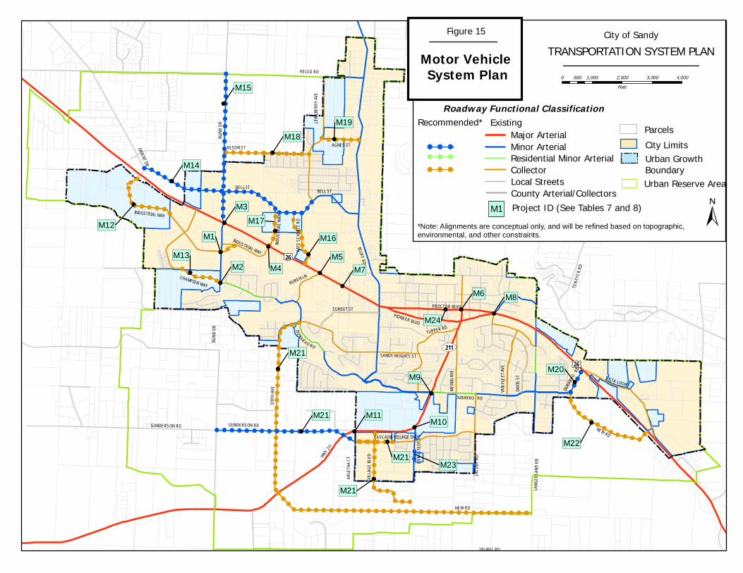
Figure 15
Motor Vehicle System Plan
Roadway Functional Classification
Residential Minor ArterialCollector
Major ArterialMinor Arterial
Local StreetsCounty Arterial/Collectors
City LimitsUrban Growth Boundary
Parcels
Urban Reserve Area
Recommended* Existing
! ! !
! ! !
! ! !
*Note: Alignments are conceptual only, and will be refined based on topographic, environmental, and other constraints.
Project ID (See Tables 7 and 8)M1
City of Sandy Transportation System Plan
Chapter 3: Modal Plans December 2011 Page 38
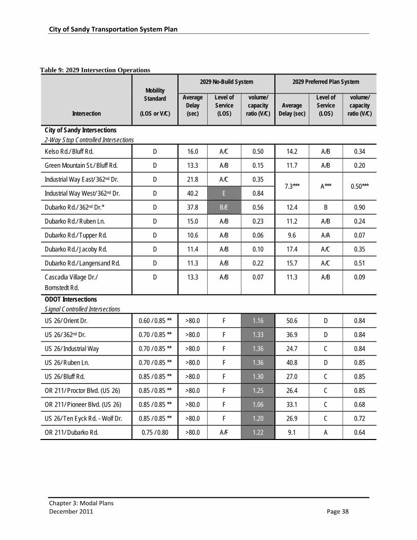
Table 9: 2029 Intersection Operations
Intersection
Mobility Standard
(LOS or V/C)
2029 No-Build System 2029 Preferred Plan System
Average Delay (sec)
Level of Service (LOS)
volume/ capacity
ratio (V/C) Average
Delay (sec)
Level of Service (LOS)
volume/ capacity
ratio (V/C)
City of Sandy Intersections
2-Way Stop Controlled Intersections
Kelso Rd./ Bluff Rd. D 16.0 A/C 0.50 14.2 A/B 0.34
Green Mountain St./ Bluff Rd. D 13.3 A/B 0.15 11.7 A/B 0.20
Industrial Way East/ 362nd Dr. D 21.8 A/C 0.35 7.3*** A*** 0.50***
Industrial Way West/ 362nd Dr. D 40.2 E 0.84
Dubarko Rd./ 362nd Dr.* D 37.8 B/E 0.56 12.4 B 0.90
Dubarko Rd./ Ruben Ln. D 15.0 A/B 0.23 11.2 A/B 0.24
Dubarko Rd./ Tupper Rd. D 10.6 A/B 0.06 9.6 A/A 0.07
Dubarko Rd./ Jacoby Rd. D 11.4 A/B 0.10 17.4 A/C 0.35
Dubarko Rd./ Langensand Rd. D 11.3 A/B 0.22 15.7 A/C 0.51
Cascadia Village Dr./
Bornstedt Rd.
D 13.3 A/B 0.07 11.3 A/B 0.09
ODOT Intersections
Signal Controlled Intersections
US 26/ Orient Dr. 0.60 / 0.85 ** >80.0 F 1.16 50.6 D 0.84
US 26/ 362nd Dr. 0.70 / 0.85 ** >80.0 F 1.33 36.9 D 0.84
US 26/ Industrial Way 0.70 / 0.85 ** >80.0 F 1.36 24.7 C 0.84
US 26/ Ruben Ln. 0.70 / 0.85 ** >80.0 F 1.36 40.8 D 0.85
US 26/ Bluff Rd. 0.85 / 0.85 ** >80.0 F 1.30 27.0 C 0.85
OR 211/ Proctor Blvd. (US 26) 0.85 / 0.85 ** >80.0 F 1.25 26.4 C 0.85
OR 211/ Pioneer Blvd. (US 26) 0.85 / 0.85 ** >80.0 F 1.06 33.1 C 0.68
US 26/ Ten Eyck Rd. - Wolf Dr. 0.85 / 0.85 ** >80.0 F 1.20 26.9 C 0.72
OR 211/ Dubarko Rd. 0.75 / 0.80 >80.0 A/F 1.22 9.1 A 0.64
City of Sandy Transportation System Plan
Chapter 3: Modal Plans December 2011 Page 39
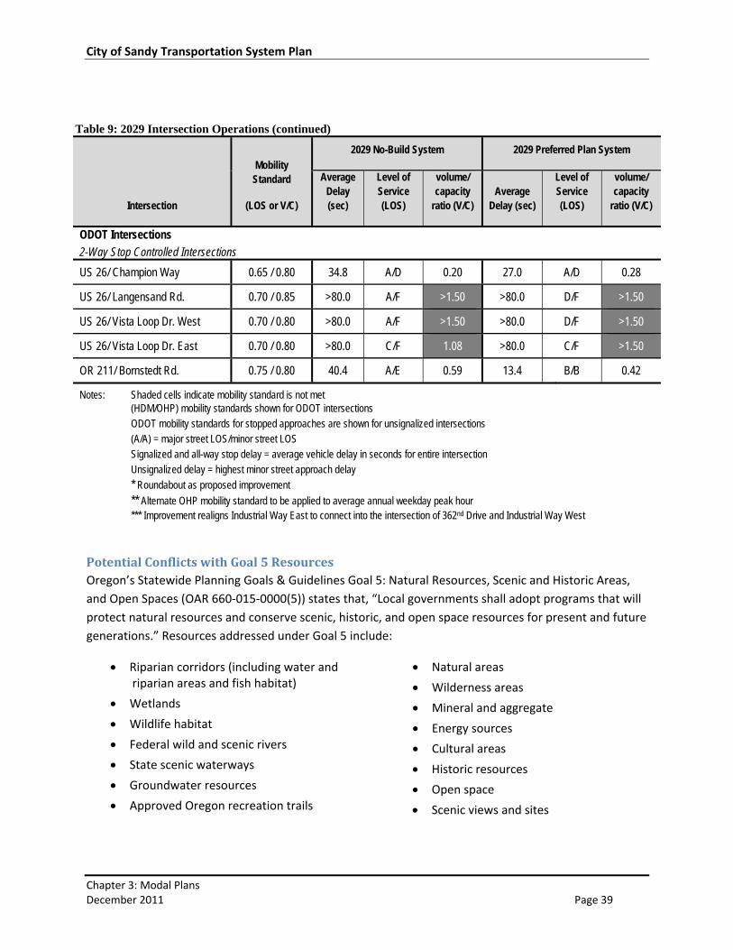
Table 9: 2029 Intersection Operations (continued)
Intersection
Mobility Standard
(LOS or V/C)
2029 No-Build System 2029 Preferred Plan System
Average Delay (sec)
Level of Service (LOS)
volume/ capacity
ratio (V/C) Average
Delay (sec)
Level of Service (LOS)
volume/ capacity
ratio (V/C)
ODOT Intersections
2-Way Stop Controlled Intersections
US 26/ Champion Way 0.65 / 0.80 34.8 A/D 0.20 27.0 A/D 0.28
US 26/ Langensand Rd. 0.70 / 0.85 >80.0 A/F >1.50 >80.0 D/F >1.50
US 26/ Vista Loop Dr. West 0.70 / 0.80 >80.0 A/F >1.50 >80.0 D/F >1.50
US 26/ Vista Loop Dr. East 0.70 / 0.80 >80.0 C/F 1.08 >80.0 C/F >1.50
OR 211/ Bornstedt Rd. 0.75 / 0.80 40.4 A/E 0.59 13.4 B/B 0.42
Notes: Shaded cells indicate mobility standard is not met (HDM/OHP) mobility standards shown for ODOT intersections ODOT mobility standards for stopped approaches are shown for unsignalized intersections (A/A) = major street LOS/minor street LOS Signalized and all-way stop delay = average vehicle delay in seconds for entire intersection Unsignalized delay = highest minor street approach delay
* Roundabout as proposed improvement
** Alternate OHP mobility standard to be applied to average annual weekday peak hour *** Improvement realigns Industrial Way East to connect into the intersection of 362nd Drive and Industrial Way West
Potential Conflicts with Goal 5 Resources Oregon’s Statewide Planning Goals & Guidelines Goal 5: Natural Resources, Scenic and Historic Areas,
and Open Spaces (OAR 660‐015‐0000(5)) states that, “Local governments shall adopt programs that will
protect natural resources and conserve scenic, historic, and open space resources for present and future
generations.” Resources addressed under Goal 5 include:
Riparian corridors (including water and riparian areas and fish habitat)
Wetlands
Wildlife habitat
Federal wild and scenic rivers
State scenic waterways
Groundwater resources
Approved Oregon recreation trails
Natural areas
Wilderness areas
Mineral and aggregate
Energy sources
Cultural areas
Historic resources
Open space
Scenic views and sites
City of Sandy Transportation System Plan
Chapter 3: Modal Plans December 2011 Page 40
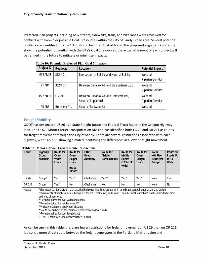
Preferred Plan projects including new streets, sidewalks, trails, and bike lanes were reviewed for
conflicts with known or possible Goal 5 resources within the City of Sandy urban area. Several potential
conflicts are identified in Table 10. It should be noted that although the proposed alignments currently
show the potential for conflict with the City’s Goal 5 resources, the actual alignment of each project will
be refined in the future to mitigate or minimize impacts.
Table 10: Potential Preferred Plan Goal 5 Impacts Project ID Roadway Location Potential Impact
M14 / M15 362nd Dr. Intersection at Bell St. and North of Bell St. Wetland
Riparian Corridor
P1 / B1 362nd Dr. Between Dubarko Rd. and the southern UGB Wetland
Riparian Corridor
P27 / B11 OR 211 Between Dubarko Rd. and Bornstedt Rd.,
South of Tupper Rd.
Wetland
Riparian Corridor
P5 / B3 Bornstedt Rd. South of Redwood St. Wetland
Freight Mobility ODOT has designated US 26 as a State Freight Route and Federal Truck Route in the Oregon Highway
Plan. The ODOT Motor Carrier Transportation Division has identified both US 26 and OR 211 as routes
for freight movement through the City of Sandy. There are several restrictions associated with each
highway, with Table 11 showing a matrix identifying the differences in allowed freight movement.
Table 11: Motor Carrier Freight Route Restrictions Route Highway
Group Number*
Route for Over-Width Loads
Route for Over-Height Loads
(up to 14’-06”)
COVP Road Authority
Route for “Triples” Combinations
Route for Mobile Homes (12’ to 14’ Wide)
Route for Over-Length Loads
Route with Use Restricted Bridges
Route for Loads Up to 14’ Wide
US 26 Group 1 Yes Yes*2 Clackamas Yes*3 Yes*4 Yes*5 None Yes
OR 211 Group 1 Yes*1 No Clackamas No No No None No
Notes: *The Motor Carrier Division has classified highways into three groups (1-3) to indicate general length, size, and weight requirements of freight vehicles: Group 1 is the least restrictive, and Group 3 has the most restrictions on the permitted vehicle and load dimensions. *1Permit required for over width operations *2Permit required for heights over 14’ *3Holiday restrictions apply east of Sandy *4Route not authorized for continuous movement east of Sandy *5Permit required for over-length loads COPV - Continuous Operation Variance Permits
As can be seen in this table, there are fewer restrictions for freight movement on US 26 than on OR 211.
It also is a more direct route between the freight generators in the Portland Metro region and
City of Sandy Transportation System Plan
Chapter 3: Modal Plans December 2011 Page 41
destinations to the east. Therefore, the management of congestion through the US 26 corridor will be
critical to maintain efficient and reliable movement of freight through the City.
Off of the US 26 corridor, the following City streets serve industrial areas.
Industrial Way (including proposed Jarl Road connection to US 26)
Champion Way
362nd Drive between US 26 and Champion Way/ Dubarko Road
Transportation Demand Management Transportation Demand Management (TDM) is the general term used to describe any action that
removes single occupant vehicle trips from the roadway network during peak travel demand periods.
TDM focuses on reducing vehicle miles traveled (VMT) and promoting alternative modes of travel. By
shifting peak travel demands on roadways, the roadway capacity can be used more efficiently, and the
City may avoid or delay building new or wider roadways.
A wide variety of TDM strategies exist, however many are tailored to larger urban areas. Strategies for
rural or smaller communities require special development and planning and should focus on increasing
travel options and creating an environment that is supportive for walking and cycling. The most effective
TDM measures for the City of Sandy may include strategies to increase parking management in the
downtown (parking time limits and pricing), carpools, increase transit services and improve facilities for
non‐vehicular modes of travel (walking, bicycling, and transit).
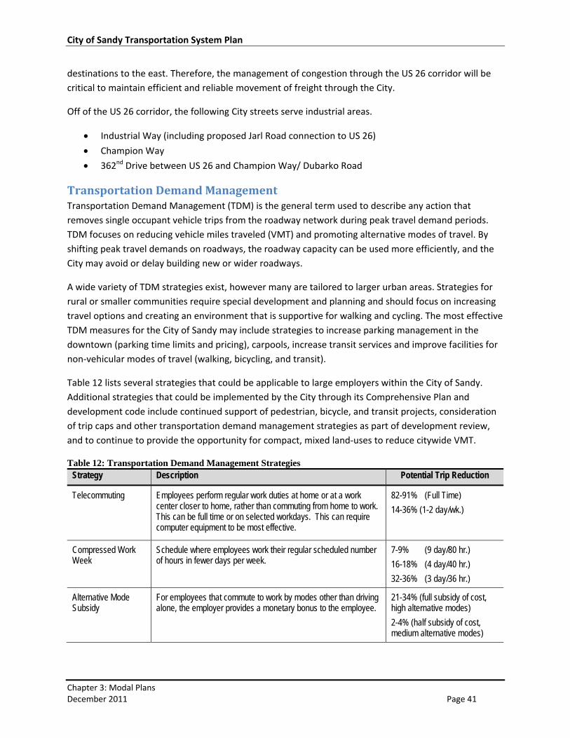
Table 12 lists several strategies that could be applicable to large employers within the City of Sandy.
Additional strategies that could be implemented by the City through its Comprehensive Plan and
development code include continued support of pedestrian, bicycle, and transit projects, consideration
of trip caps and other transportation demand management strategies as part of development review,
and to continue to provide the opportunity for compact, mixed land‐uses to reduce citywide VMT.
Table 12: Transportation Demand Management Strategies Strategy Description Potential Trip Reduction
Telecommuting Employees perform regular work duties at home or at a work center closer to home, rather than commuting from home to work. This can be full time or on selected workdays. This can require computer equipment to be most effective.
82-91% (Full Time)
14-36% (1-2 day/wk.)
Compressed Work Week
Schedule where employees work their regular scheduled number of hours in fewer days per week.
7-9% (9 day/80 hr.)
16-18% (4 day/40 hr.)
32-36% (3 day/36 hr.)
Alternative Mode Subsidy
For employees that commute to work by modes other than driving alone, the employer provides a monetary bonus to the employee.
21-34% (full subsidy of cost, high alternative modes)
2-4% (half subsidy of cost, medium alternative modes)
City of Sandy Transportation System Plan
Chapter 3: Modal Plans December 2011 Page 42
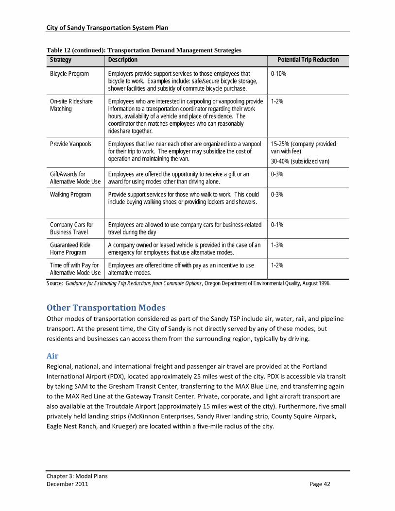
Table 12 (continued): Transportation Demand Management Strategies
Strategy Description Potential Trip Reduction
Bicycle Program Employers provide support services to those employees that bicycle to work. Examples include: safe/secure bicycle storage, shower facilities and subsidy of commute bicycle purchase.
0-10%
On-site Rideshare Matching
Employees who are interested in carpooling or vanpooling provide information to a transportation coordinator regarding their work hours, availability of a vehicle and place of residence. The coordinator then matches employees who can reasonably rideshare together.
1-2%
Provide Vanpools Employees that live near each other are organized into a vanpool for their trip to work. The employer may subsidize the cost of operation and maintaining the van.
15-25% (company provided van with fee)
30-40% (subsidized van)
Gift/Awards for Alternative Mode Use
Employees are offered the opportunity to receive a gift or an award for using modes other than driving alone.
0-3%
Walking Program Provide support services for those who walk to work. This could include buying walking shoes or providing lockers and showers.
0-3%
Company Cars for Business Travel
Employees are allowed to use company cars for business-related travel during the day
0-1%
Guaranteed Ride Home Program
A company owned or leased vehicle is provided in the case of an emergency for employees that use alternative modes.
1-3%
Time off with Pay for Alternative Mode Use
Employees are offered time off with pay as an incentive to use alternative modes.
1-2%
Source: Guidance for Estimating Trip Reductions from Commute Options, Oregon Department of Environmental Quality, August 1996.
Other Transportation Modes Other modes of transportation considered as part of the Sandy TSP include air, water, rail, and pipeline
transport. At the present time, the City of Sandy is not directly served by any of these modes, but
residents and businesses can access them from the surrounding region, typically by driving.
Air Regional, national, and international freight and passenger air travel are provided at the Portland
International Airport (PDX), located approximately 25 miles west of the city. PDX is accessible via transit
by taking SAM to the Gresham Transit Center, transferring to the MAX Blue Line, and transferring again
to the MAX Red Line at the Gateway Transit Center. Private, corporate, and light aircraft transport are
also available at the Troutdale Airport (approximately 15 miles west of the city). Furthermore, five small
privately held landing strips (McKinnon Enterprises, Sandy River landing strip, County Squire Airpark,
Eagle Nest Ranch, and Krueger) are located within a five‐mile radius of the city.
City of Sandy Transportation System Plan
Chapter 3: Modal Plans December 2011 Page 43
Rail Regional, national, and international freight and passenger rail service are available for the residents and
businesses of Sandy at several locations in the Portland Metro Region. Freight rail services are available
from three national carriers (Burlington Northern Santa Fe Railroad, Union Pacific Railroad, and
Southern Pacific Railroad), as well as several other short line freight rail companies. Long‐haul passenger
rail service is available from Amtrak.
Freight rail services are also available in Hood River through the Union Pacific Railroad line in the
Columbia River Gorge, but there are no intermodal facilities of significance in the area for transferring
goods.
Water Regional, national, and international freight water transport is currently available at the Port of
Portland. Tourist‐oriented passenger water transport service is also available in the Portland Metro
Region and the Gorge.
Pipeline/ Transmission Line Natural gas service is available in the City of Sandy through feeder lines, but no major transmission
pipelines for natural gas, oil, or any other commodity are currently available in the city.