Embed Size (px)
Citation preview

______________________________________________________________________________________ Primary Treatment 3-1
CHAPTER 3 1
PRIMARY TREATMENT 2 3 Learning Objectives 4 5
This chapter covers the major concepts associated with primary treatment. By the end of 6 this chapter, a student should be able to: 7
• Define the objective of the primary treatment process; 8 • Distinguish between primary sedimentation tanks and secondary clarifiers; 9 • Identify the basic principle underlying the primary treatment process; 10 • Describe the components of primary sedimentation tanks including inlet and 11
outlet structures; 12 • Explain the main considerations for sludge and scum removal and disposal; 13 • List the factors that affect primary sedimentation tank efficiency; 14 • Describe the key elements of process control and testing as these relate to the 15
operation of the primary sedimentation tank; 16 • Outline the key troubleshooting and maintenance concerns related to primary 17
treatment; and 18 • Identify the specific safety concerns associated with the primary sedimentation 19
process. 20 21
22 Introduction 23 24 25 26
Sewers are designed to provide a wastewater velocity of at least 0.6 m/s (2.0 ft/sec). 27 Because the wastewater in collection systems moves relatively fast, the solids stay in 28 suspension. When wastewater enters a treatment plant, it first passes through a bar screen 29 which removes the larger solids, or through a grinder or comminutor, which reduces the size of 30 the larger particles. After screening or grinding, the wastewater flows to a grit chamber where 31 heavier undesirable solids are removed. The velocity of the wastewater to this point has kept 32 these solids in suspension. In the grit tank, the speed of the wastewater is reduced to about 0.3 33 m/s (1.0 ft/sec). This decreased velocity allows the inorganic solids or grit to settle out, but still 34 allows the lighter organic solids to remain in suspension. If the speed of the wastewater is 35 reduced to below 0.3 m/s (1.0 ft/sec), heavier materials will settle and lighter materials will rise to 36 the surface. This solids-liquids separation using a reduced velocity and a force such as gravity is 37 known as sedimentation. This is what occurs in the primary treatment process at a wastewater 38 treatment plant. 39 40
Both organic and inorganic solids are present in wastewater, and both can be either 41 suspended or dissolved. Settleable solids are the portion of suspended solids that readily settle in 42 a primary sedimentation tank when the wastewater velocity is reduced to a fraction of a meter or 43 foot per second. Typically, 90 – 95% of settleable solids settle out during primary treatment 44 (Figure 3.1). Colloidal solids, which are finely divided solids, are too fine to settle within the usual 45 detention times of a primary sedimentation tank. Colloidal solids readily pass through the primary 46 treatment process and are treated in the secondary treatment process. Primary sedimentation 47 tanks reduce the wastewater velocity to less than 0.3 m/s (1.0 ft/sec) and allow these settleable 48 solids to separate from the waste stream. This process also removes a percentage of suspended 49 solids as well as Biochemical Oxygen Demand (BOD) that are associated with these solids. 50 Typical removal efficiencies that can be achieved in primary treatment are as follows in Table 3.1. 51
52 Table 3.1 - Removal Efficiencies of Primary Treatment 53

______________________________________________________________________________________ 3-2 Operations Training/Wastewater Treatment
1 Parameter Removal Efficiency Settleable Solids 90 – 95 % Suspended Solids 50 – 65 % BOD 20 – 35 %
2 3 4
5 6
Figure 3.1 Schematic of Primary Treatment Process 7 8 9 10
Better primary treatment efficiencies can be expected with fresh wastewater than with 11 wastewater that has turned septic because of long travel times in the collection system. Septic 12 wastewater contains anaerobic bacteria that produce gas. This gas, in turn, causes the solids to 13 be buoyed as nitrogen bubbles rise. 14 15
Primary settling tanks can be rectangular, square, or round. The shape of the tank does 16 not affect its removal efficiencies. As you can see below, a primary settling tank is usually 17 designed with the following parameters: 18 Primary Settling: 19
• Detention time of 1 - 2 hrs; 20 • Surface overflow rate of 32 600 – 48 900 L/m2·d (800 – 1200 gpd/ft2) for average 21
flow; 22 • 81 500 –122 000 L/m2·d (2000 – 3000 gpd/ft2) for peak flow; and 23 • Weir overflow rate, 124 000 – 496 000 L/m·d (10 000 – 40 000 gpd/ft) 24 25
Primary Settling with Waste Activated Sludge Return (Cosettling): 26 • Detention time of 1 – 2 hrs; 27

______________________________________________________________________________________ Primary Treatment 3-3
• Surface overflow rate of 24 420 – 32 560 L/m2·d (600 – 800 gpd/ft2) for average 1 flow; 2
• 48 840 – 69 190 L/m2·d (1200 – 1700 gpd/ft2) for peak flow; and 3 • Weir overflow rate, 124 000 – 496 000 L/m·d (10 000 – 40 000 gpd/ft) 4 5
These design parameters may change slightly based on site-specific conditions. We will 6 examine these parameters in greater detail later in the chapter. 7
8 Primary and secondary clarifiers essentially share the same primary function: to remove 9
solids from water using sedimentation. They also have similar configurations and designs. 10 However, based on the design parameters listed above, we can examine some fundamental 11 differences between primary and secondary clarifiers. The average surface overflow rate for a 12 secondary clarifier ranges from 24 000 to 33 000 L/m2·d (600 to 800 gpd/ft2) and a wier overflow 13 rate of 125 000 to 250 000 L/m·d (10 000 to 20 000 gpd/ft). These numbers are lower than those 14 of a primary settling tank. What these numbers translate to is that a secondary tank is typically 15 larger in diameter and surface area than a primary tank. However the depth of a primary tank is 16 usually somewhat greater than that of a secondary tank. This means secondary tanks are larger 17 and more spread out. The reason for this is that secondary tanks typically remove solids that are 18 much lighter in comparison to those removed by a primary tank. Therefore, a longer detention 19 time is needed. This “spread out” design allows for a proper volume of wastewater to pass 20 through with adequate detention time and also reduces the depth to which the solids have to 21 settle. 22 23 Tank Configurations and Components 24 25
Different names can be used to refer to primary treatment tanks. They are alternately 26 called clarifiers, sedimentation basins, or settling tanks. In this chapter, we will refer to primary 27 treatment units as primary settling tanks or primary tanks. Despite its location on a treatment 28 plant or its shape, the purpose of all settling tanks is the same - to reduce wastewater velocity 29 and mixing so that settling and flotation will occur. It is important to realize that only the settleable 30 solids are removed in the settling tank. Lighter solid material remains in the wastewater or floats 31 to the surface and must be removed through different means. Primary tanks are typically located 32 right after preliminary treatment. If the primary tank is not removing enough settleable solids from 33 the wastewater, increased oxygen demand can result and inhibit later biological processes. 34 However, if too many settleable solids are removed, there may not be enough organic matter for 35 the biological system to perform properly. 36 37
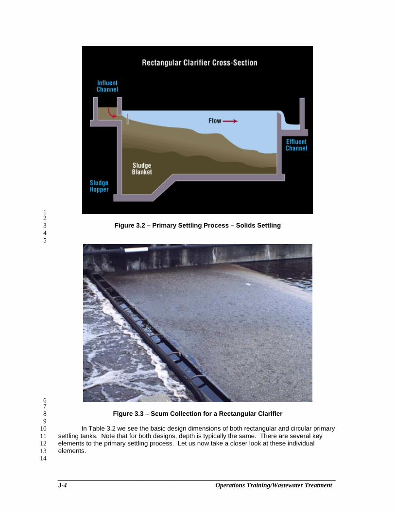
When wastewater is placed in a cone (such as an Imhoff cone) and allowed to sit, 38 settleable solids settle to the bottom, and lighter floatable solids rise to the top. This is essentially 39 the same thing that happens in a primary settling tank (sedimentation). The settling process relies 40 on gravity to separate the solid material from the liquid. Settling tanks are simply large tanks 41 designed to distribute flow uniformly throughout the tank. This uniform distribution helps reduce 42 the wastewater velocity and amount of mixing equally throughout the tank. Under these 43 conditions, solid materials, which were carried in suspension by the waste flow, will settle to the 44 bottom as sludge or float to the surface as scum. Colloidal, or finely divided, solids that will not 45 settle and dissolved solids will remain in the liquid and be carried on for further processing. 46 Figures 3.2 and 3.3 show what happens in a rectangular settling tank. Flow entering from the left 47 is evenly distributed throughout the tank. As the wastewater flows through the tank, heavier solids 48 settle to the bottom where they are removed (Figure 3.2). At the same time, lighter material or 49 scum rises to the top, where it too is removed (Figure 3.3). The same type of action occurs in a 50 circular settling tank, except that the wastewater enters the tank at the middle and flows out 51 toward the perimeter of the tank. 52 53
54 55 56
______________________________________________________________________________________ 3-4 Operations Training/Wastewater Treatment
1 2
Figure 3.2 – Primary Settling Process – Solids Settling 3 4 5
6 7
Figure 3.3 – Scum Collection for a Rectangular Clarifier 8 9
In Table 3.2 we see the basic design dimensions of both rectangular and circular primary 10 settling tanks. Note that for both designs, depth is typically the same. There are several key 11 elements to the primary settling process. Let us now take a closer look at these individual 12 elements. 13 14

______________________________________________________________________________________ Primary Treatment 3-5
Table 3.2 Dimensions and Parameters for Rectangular and Circular Primary Settling 1 Tanks 2
3 Inlet 4 The settling tank inlet slows down the velocity of wastewater entering the tank and 5
distributes the flow across the tank. If more than one settling tank is being used, a splitter box 6 placed before the inlet divides the flow evenly into each tank. Settling tanks can use a variety of 7 inlet structures. 8 9
Figure 3.4 illustrates a spaced port opening arrangement for a rectangular primary tank. 10 The diagram also shows the action of a spaced port opening inlet structure. This inlet structure 11 reduces the velocity of wastewater entering the tank and distributes the flow across the tank. The 12 other main type of rectangular clarifier inlet structure includes an elbow that directs the influent 13 flow below the surface and down, rather than straight across. Often, a "tee" structure is used so 14 that the pipe can be easily cleaned. If the "tee" structure is omitted, a baffle is needed near the 15 inlet to help spread the flow of wastewater evenly throughout the tank. 16 17
18 19
Figure 3.4 Inlet Flow Distribution for a Rectangular Primary Tank 20 21 The usual inlet arrangement in a circular settling tank is a vertical pipe in the center of the 22
tank with the influent well at the top (Figure 3.5). Another design alternative is the side-entry 23 feed, with the inlet pipe coming from the sidewall of the tank to the center influent well. Whether 24 center or side-entry feed is used, this influent well typically has a diameter that is 15 to 20% of the 25 tank’s diameter. A circular baffle around this inlet forces the wastewater to flow toward the 26 bottom of the tank around the pipe. As we will discuss shortly, you may also find baffling near the 27 outlet structures of circular tanks to help with flow distribution. In all settling tanks, the purpose of 28 the inlet structure is to reduce the velocity of the wastewater entering the tank and distribute the 29 flow evenly across the tank. This even distribution is important for proper settling. 30 31

______________________________________________________________________________________ 3-6 Operations Training/Wastewater Treatment
1 2
Figure 3.5 Inlet Flow Distribution for a Circular Primary Tank 3 4 5
Flow Distribution 6 There can be serious consequences if the inlet does not distribute the flow evenly 7
throughout the tank. If the speed of the wastewater is greater in some areas of the tank than 8 others, a condition called "short-circuiting" (Figure 3.6) can occur. In places where the wastewater 9 is moving faster, particles that are suspended in the wastewater may not have a chance to settle 10 out. They will be held in suspension and will pass through to the discharge end of the tank. It is 11 desirable to maintain even flow distribution to prevent short-circuiting in the settling tank. A baffle 12 is commonly used to reduce short-circuiting. The flow of wastewater hits the baffle and disperses 13 evenly, ensuring a good flow in the tank. In the circular settling tank, the wall of the influent well 14 acts as the baffle. Finally, the overflow weirs must be perfectly level to ensure good flow 15 distribution and help prevent short-circuiting. 16 17
18 19
Figure 3.6 Short-Circuiting in a Primary Tank 20

______________________________________________________________________________________ Primary Treatment 3-7
1 Also proper flow distribution and baffling is essential to help deal with the formation of 2
density currents (Figure 3.7). Density currents are formed by the improper inlet distribution of 3 influent solids. These solids are denser than the clarifier contents and immediately begin to move 4 down towards the sludge blanket. However, due to improper inlet distribution it retains a higher 5 velocity than the rest of the contents. This newly formed current will simply deflect off of the 6 sludge blanket and use its momentum to carry itself to the clarifier outlet structure, often carrying 7 sludge from the blanket with it. Baffles may be installed near the outlet weirs to help prevent this 8 solids loss. These baffles will be discussed further as we discuss primary tank outlet structures. 9 10
Figure 3.7 Formation of a Density Current in a Circular Primary Tank 11 12
Settling 13 If the flow is properly distributed, then the effective separation of settleable solids from 14
wastewater in the settling tank can occur. As described earlier, the best way to obtain this 15 separation is to allow the liquid to remain very still for several hours. This allows most solids in the 16 liquid to settle to the bottom of the settling tank, where they are removed for further processing. 17 Any solids that float to the surface are removed by scum collection devices and further 18 processed. Most organic settleable solids weigh only slightly more than water. So they settle very 19 slowly. Settling tanks are designed with this fact in mind. The velocity of the liquid in the settling 20 tank is slowed down to a fraction, approximately 0.001 m/s (0.003 ft/sec), of its influent velocity as 21 compared to about 0.3 m/s (1.0 ft/sec) in the grit chamber, and at least 0.6 m/s (2.0 ft/sec) in the 22 sewer. As the wastewater moves across the settling tank, heavier suspended solids have enough 23 time to settle to the bottom of the tank. Some of the lighter suspended solids will also settle, but 24 others, are so light, that they pass completely through the tank. Again, for proper settling to occur 25 in the settling tank, the liquid must move very slowly. The wastewater must stay in the settling 26 tank long enough for solid particles to settle. If the tank is too small for the volume of flow entering 27 it, too many particles will exit with the tank effluent. 28 29
Detention Time 30 The length of time that wastewater stays in the settling tank is called the detention time. 31
Approximately 1– 2 hours of detention time are needed in the primary settling tank as was noted 32 at the beginning of this chapter. The exact time depends on many factors such as the influent 33 flow rate and the removal requirements needed by downstream processes. If the detention time is 34 too long, solids may become septic and float to the surface. High suspended solids levels in the 35 primary effluent and subsequent odors may result. A secondary clarifier requires a longer 36 detention time than a primary settling tank because the light and fluffy activated sludge particles 37 do not settle as easily as the heavier solids removed in a primary tank. How efficiently the settling 38 tank removes settleable solids depends on how slow the liquid moves (influent velocity) and on 39 the detention time. Let us look at an example of calculating detention time. 40 41
Detention time = rate Flow
tank settlingprimary of Volume 42
Given the following dimensions and flow rate for a circular primary settling tank, we will 43 calculate the detention time: 44
Tank diameter = 7 m 45 Tank depth = 4 m 46 Flow rate to tank = 1 892 400 L/d 47
48 First, calculate the surface area of the tank in m2: 49 50
Surface area, m2 = π2
2m,Diameter⎟⎠
⎞⎜⎝
⎛ = π 2
2m7⎟⎠
⎞⎜⎝
⎛ = π(3.5 m)2 = 38.465 m2 51
52 Next, calculate the volume of the tank in liters: 53

______________________________________________________________________________________ 3-8 Operations Training/Wastewater Treatment
Volume of settling tank, L = (Surface area, m2)(Depth, m)(3m 1L 1000 ) 1
2
Volume of settling tank, L = (38.465 m2)(4 m)(3m 1L 1000 ) = 153 860 L 3
Then, convert the flow rate to L/h: 4 (1 892 400 L/d)(1d /24 h) = 78 850 L/h 5 6 Now, calculate the detention time: 7 8
Detention time, h =
hL 850 78
L 860 153 = 1.95 h, round up to 2 hours 9
10 Let us now perform the same calculation using English units. 11 12
Given the following dimensions and flow rate for a circular primary settling tank, we will 13 calculate the detention time: 14
Tank diameter = 26 ft 15 Tank depth = 10 ft 16 Flow rate to tank = 476 315 gpd 17
18 First, calculate the surface area of the tank in ft2: 19 20
Surface area, ft2 = π2
2ft,Diameter⎟⎠
⎞⎜⎝
⎛ = π2
2ft 26⎟⎠
⎞⎜⎝
⎛ = π(13 ft)2 = 530.66 ft2 21
22 Next, calculate the volume of the tank in gallons: 23
Volume of settling tank, gal = (Surface area, ft2)(Depth, ft)(3ft 1gal 7.48 ) 24
25
Volume of settling tank, gal = (530.66 ft2)(10 ft) (3tf 1gal 7.48 ) = 39 693 gal 26
Then, convert the flow rate to gal/hr: 27 (476 315 gal/d)(1d /24 h) = 19 846 gal/hr 28 29 Now, calculate the detention time: 30 31
Detention time, hr =
hrlag 846 19
lag 693 39 = 2 hr 32
33 34 35
Overflow Rate 36 The surface overflow rate is a measure of how rapidly wastewater moves through the 37
settling tank. When we talk about surface overflow rate, we are referring to the number of gallons 38 going through the settling tank each day for each square foot of surface area in the tank, or the 39 number of liters for each square meter per day. In other words, we are looking at the hydraulic 40 wastewater load for each square meter, or square foot, of surface area in the settling tank each 41 day. This diagram (Figure 3.8) might help you understand what we mean by the surface overflow 42 rate. Imagine placing a net on the surface of the settling tank liquid. Each space in this net equals 43

______________________________________________________________________________________ Primary Treatment 3-9
one square meter, or one square foot. Focus on just one of these squares. Surface overflow rate 1 is the number of liters flowing through one square meter each day, or the number of gallons 2 flowing through this one square foot each day. 3
4
5 6
Figure 3.8 Representation of Surface Overflow Rate 7 8 As we stated earlier in this chapter, for proper settling, the suggested surface overflow 9
rate for primary tanks varies from 32 600 – 122 000 L/m2·d (800 – 3000 gpd/ft2), depending on 10 the nature of the solids and the treatment required. Let us look at an example calculation for 11 determining the surface overflow rate. The surface overflow rate is defined as the loading across 12 the surface of your primary tank defined as follows: 13 14
Surface overflow rate = tank the of area Surface
tank the to rateFlow 15
16 For our sample calculation, we will use the same dimensions and flow rates as our 17
previous example. 18 Given: 19 Tank diameter = 7 m 20 Flow rate to tank = 1 892 400 L/d 21
22 First, calculate the surface area of the tank in m2: 23
24
Surface area, m2 = π2
2m,Diameter⎟⎠
⎞⎜⎝
⎛ = π 2
2m7⎟⎠
⎞⎜⎝
⎛ = π(3.5 m)2 = 38.485 m2 25
Next, simply divide the flow rate by the surface area: 26 27
Surface overflow rate, L/m2·d = 2m38.485dL 400 892 1
= 49 173 L/m2·d round up to 49 200 L/m2·d 28

______________________________________________________________________________________ 3-10 Operations Training/Wastewater Treatment
1 Let us now perform the same calculation using English units. 2 Given: 3
Tank diameter = 26 ft 4 Flow rate to tank = 476 315 gpd 5
6 First, calculate the surface area of the tank in ft2: 7
8
Surface area, ft2 = π2
2ft,Diameter⎟⎠
⎞⎜⎝
⎛ = π2
2ft 26⎟⎠
⎞⎜⎝
⎛ = π(13 ft)2 = 530.93 ft2 9
10 Next, simply divide the flow rate by the surface area: 11 12
Surface overflow rate, gpd/ft2 = 2ft530.93d
gal 315 476 = 897 gpd/ft2 round up to 900 gpd/ft2 13
14 Efficiency 15 Many factors can affect the efficiency of a settling tank. One factor is the type of solids in 16
the system. This is especially important if a large amount of industrial waste is present. Another 17 factor is the age of the wastewater when it reaches the plant. Older wastewater becomes stale or 18 septic, and solids will not settle properly because gas bubbles form and cause them to float. 19 Settling tank efficiency also depends on the rate of wastewater flow, as we have discussed. 20 When flow rates are high, detention times decrease and settling is less efficient. Another 21 important factor is the cleanliness and mechanical condition of the settling tank; poor 22 housekeeping or broken equipment can reduce settling efficiency. At this point you should ask 23 yourself how well your primary settling tank is performing during proper operation. In the primary 24 settling tank, about 50 – 65% of the suspended solids will be removed. If we look at just the 25 settleable solids, close to 100% should be removed. Because some of the suspended solids are 26 organic, BOD will also decrease by approximately 20 – 35%. The best way to determine the 27 efficiency of a primary tank is to examine both the tank influent and effluent characteristics, such 28 as BOD and suspended solids. Using these numbers you can determine the removal efficiency 29 of your primary settling tank. Let us look at a brief example. Removal efficiency is calculated as 30 follows: 31 32
Removal efficiency, % = In Parameter
Out Parameter - In Parameter x 100% 33
We are given the following data: 34 Primary Influent BOD = 180 mg/L 35 Primary Effluent BOD = 130 mg/L 36 Now we can calculate our removal efficiency: 37 38
Removal efficiency, % = L/gm 180
L/gm 130 - L/gm 180 x 100% = 27.8% round up to 28% 39
Based on our design parameters, this an acceptable removal efficiency for our primary 40 settling tank. 41 42
Outlet 43 So far, we have discussed the settling tank inlet and the clarification that occurs in the 44
settling tank. Now let us look at the clarifier outlets. Wastewater leaves the settling tank by flowing 45 over weirs and into effluent troughs or launders, as shown in Figure 3.9. The purpose of a weir is 46 to allow a thin film of the clearest water to overflow the tank. A high velocity near the weir can pull 47 settling solids into the effluent. The length of the weir in the settling tank compared to the flow is 48

______________________________________________________________________________________ Primary Treatment 3-11
important in preventing high velocities. A baffle at the outlet end of a rectangular tank or around 1 the edge of a circular tank helps prevent short-circuiting and floating solids from leaving the tank. 2 As we mentioned earlier, baffles are also used near the outlet weirs (Figure 3.10) to help deal 3 with density currents. Two of the more common types used are the Crosby and Stamford 4 peripheral baffles. 5 6
7 8
Figure 3.9 Effluent Weirs and Launder for a Primary Settling Tank 9 10

______________________________________________________________________________________ 3-12 Operations Training/Wastewater Treatment
1 2
Figure 3.10 Peripheral Baffles for a Primary Settling Tank 3 4
Operators should make sure that flow from settling tanks is uniformly distributed when 5 overflowing the weir. Most tank weirs can be adjusted and made level so that effluent flow is 6 uniformly distributed. Assuming that flow over the weir is uniformly distributed, one way to 7 determine whether you have sufficient weir length is to calculate the daily flow over each meter, 8 or each foot, of weir. This measurement is called the weir overflow rate. The weir overflow rate 9 equals the number of liters per meter of weir per day, or the number of gallons of wastewater that 10 flows over one foot of weir per day. 11 12
Weir overflow rate = (ft) m weir,of Length(gpd) L/d flow, Wastewater 13
14 Secondary clarifiers with higher effluent quality requirements generally need lower weir overflow 15 rates than primary tanks. Let us perform a sample calculation for the weir overflow rate using the 16 same parameters as our other examples including the length of the weir. 17 18
Given: 19 Tank diameter = 7 m 20 Length of weir = 22 m 21 Flow rate to tank = 1 892 400 L/d 22
23
Weir overflow rate, L/m·d = m weir,of LengthL/d flow, Wastewater 24
25
= m 22
L/d 400 892 1 = 86 018.18 L/m·d, round up to 86 020 L/m·d 26
27 Let us now perform the same calculation in English units. 28
______________________________________________________________________________________ Primary Treatment 3-13
Given: 1 Tank diameter = 26 ft 2 Length of weir = 82 ft 3 Flow rate to tank = 476 315 gpd 4
5
Weir overflow rate, gpd/ft = ft weir,of Lengthgpd flow, Wastewater 6
7
= ft 82
gpd 315 476 = 5808.72 gpd/ft, round up to 5810 gpd/ft 8
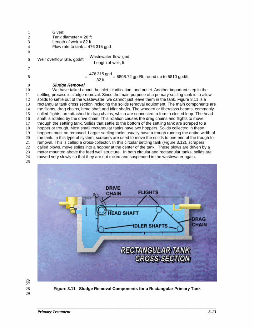
Sludge Removal 9 We have talked about the inlet, clarification, and outlet. Another important step in the 10
settling process is sludge removal. Since the main purpose of a primary settling tank is to allow 11 solids to settle out of the wastewater, we cannot just leave them in the tank. Figure 3.11 is a 12 rectangular tank cross section including the solids removal equipment. The main components are 13 the flights, drag chains, head shaft and idler shafts. The wooden or fiberglass beams, commonly 14 called flights, are attached to drag chains, which are connected to form a closed loop. The head 15 shaft is rotated by the drive chain. This rotation causes the drag chains and flights to move 16 through the settling tank. Solids that settle to the bottom of the settling tank are scraped to a 17 hopper or trough. Most small rectangular tanks have two hoppers. Solids collected in these 18 hoppers must be removed. Larger settling tanks usually have a trough running the entire width of 19 the tank. In this type of system, scrapers are used to move the solids to one end of the trough for 20 removal. This is called a cross-collector. In this circular settling tank (Figure 3.12), scrapers, 21 called plows, move solids into a hopper at the center of the tank. These plows are driven by a 22 motor mounted above the feed well structure. In both circular and rectangular tanks, solids are 23 moved very slowly so that they are not mixed and suspended in the wastewater again. 24 25
26 27
Figure 3.11 Sludge Removal Components for a Rectangular Primary Tank 28 29

______________________________________________________________________________________ 3-14 Operations Training/Wastewater Treatment
1
2 3
Figure 3.12 Sludge Removal Components for a Circular Primary Tank 4 5 After settled sludge has been moved to the sludge hopper, it still has to be removed 6
completely from the tank. The method used to remove this sludge will affect the sludge 7 stabilization process. For example, if your plant uses anaerobic digesters, the smaller the volume 8 of sludge that you pump into the digester, the fewer digester problems you will have. Because 9 most plants' digesters are built to handle only the minimum volume necessary for continuous 10 treatment, it is important to pump sludge wisely. All sludge must be removed from the primary 11 tanks, so it should be concentrated into the least possible volume. This means pumping the 12 sludge with as little water as possible. The solids collected in the primary tank hopper are 13 pumped to the sludge stabilization process or solids handling process. What happens to the 14 primary sludge will depend on the plant design. Solids handling systems vary from plant to plant 15 and include the use of aerobic digesters, anaerobic digesters, centrifuges, belt presses, and other 16 solids handling processes. 17
18 As previously discussed, the amount of sludge pumped from the primary tanks is an 19
important factor, and the type of equipment used to remove the sludge varies. Typically, 20 treatment plants use piston pumps, diaphragm pumps, or progressing cavity pumps to remove 21 sludge from primary tanks (Figure 3.13). Some plants use centrifugal-type pumps. However, the 22 capacity of centrifugal pumps can be affected by the solids concentration and sludge 23 characteristics. Many primary sludge-pumping systems have variable pump speed capability, 24 such as manually adjusted belts, variable-frequency drives, or adjustable-gear units. Adjustable 25 pump outputs reduce the chance of coning in the sludge hopper and subsequent pumping of 26 water only. Also, adjusting the pump rates can benefit the solids-handling facilities. Primary 27 sludge-pumping systems typically have start and stop timers. Some plants use timers to start the 28 pumping system and density meters to stop the pumps. Many plants today use programmable 29 computers on their sludge-withdrawal systems, while others use manual timing operations. 30 31

______________________________________________________________________________________ Primary Treatment 3-15
1 2
Figure 3.13 Primary Sludge Pumps – Piston Pump 3 4
Scum Removal 5 The final main step in the primary clarification process is scum (skimmings) removal. 6
Scum is removed from all primary tanks. In rectangular tanks, the flights that scrape the bottom 7 sludge in one direction also move across the surface of the liquid in the opposite direction, 8 pushing scum that has floated to the surface to a trough at the end of the tank. As shown in 9 Figure 3.14, the scum trough lies along the edge of the tank. The trough is actually a long pipe 10 with an open slot cut across the top. To remove scum from the tank, this pipe, the scum trough, 11 rotates to allow the scum to enter the trough through the open slot. Scum is removed from the 12 tank by turning the slotted pipe toward the scum, so that the scum is carried into the pipe by the 13 in rushing water. This pipe or scum trough is connected to a scum pit where the scum is stored. 14 The operator must take care to skim the maximum amount of scum while collecting the minimum 15 of water. In circular tanks, a surface blade pushes the scum to a hopper located at the edge of 16 the tank, as shown in Figure 3.15. The hopper drains through a pipe into the scum pit. Primary 17 tanks will also often incorporate scum baffles to prevent scum from making their way to the 18 effluent weirs. These baffles can best be described as a vertical extension of the sidewalls. 19 20

______________________________________________________________________________________ 3-16 Operations Training/Wastewater Treatment
1 2
Figure 3.14 Scum Removal for a Rectangular Primary Tank 3 4 5
6 7
Figure 3.15 Scum Removal for a Circular Primary Tank 8 9

______________________________________________________________________________________ Primary Treatment 3-17
Because of the kinds of material collected in a scum pit, it is strongly recommended that 1 no scum be pumped into the anaerobic digester. However, in many plants, the anaerobic digester 2 is the only place the scum can be sent. Scum layers can cause serious problems in digesters with 3 poor or no mixing. Scum from the scum pit should be dewatered or concentrated and disposed of 4 in an approved manner such as landfilling or incineration. 5
6 Chemical Addition 7 It may be necessary, based on the quality of your incoming solids, to use chemical 8
settling aids to assist in primary treatment. You may also need to use chemical for odor control if 9 you live in a sensitive, heavy-populated area. Some of the chemicals commonly used are: 10
• Polymers for improving settling; 11 • Ferric chloride and alum to help remove phosphorus and improve settling; and 12 • Chlorine or potassium permanganate to for odor control. 13
14 Remember to determine the optimum dosage of chemical for your primary tank before 15
adding. This is typically carried out through jar testing. You will need to repeat this dosage 16 analysis regularly since influent conditions regularly change. You will also need to allow for 17 proper mixing. A good location for a chemical addition point is in the influent pipe just prior to 18 reaching the primary tank’s inlet structure (Figure 3.16). Keep in mind, if you decide to use 19 chemicals that new safety guidelines must be instituted for your primary tanks. 20 21
Figure 3.16 Chemical Addition for a Primary Tank 22 23 Process Control 24 25 This section covers some of the basic controls you should know about when operating a 26 primary treatment system. We will also examine some troubleshooting concerns as we examine 27 each process control component. 28 29
Visual Observations 30 The most important process control tool you have in operating a primary tank is visual 31
observation. Check frequently to see what is happening in the tank. Make sure all of the inlet 32 channels are clear of obstructions or anything that can block the flow. Remove any obstructions 33 in the inlet channel immediately. If you have more than one primary tank, check frequently to see 34 that the flow to each of the tanks is equal. A good way to estimate tank flow is to observe the 35 amount of flow over the effluent weirs. Check the effluent weirs to make sure they are all level 36 and clean. Effluent weirs that are not level or are blocked by debris can cause uneven flow over 37 the outlet, which can lead to short-circuiting. Another thing that you can observe visually is any 38 build up of sludge on baffles, walls, or channels. We said earlier that primary tank efficiency 39 depends in part on keeping the unit clean. The operator who understands this knows that sludge 40 build-ups will affect tank efficiency. He or she must remove these build-ups regularly. 41 42
Flow 43 Do not forget to check your plant flow frequently. After a while, you will know how much 44
flow your plant can handle without running into problems. Obviously, if you receive more flow than 45 your plant was designed to handle, you will face problems, especially if this increased flow 46 continues for an extended period of time. Sludge at the bottom of the tank will be stirred up and 47 can exit the tank in the effluent. Figure 3.17 shows a hydraulically overloaded primary tank. This 48 problem will not happen every time the flow increases. In fact, your primary tank should be able to 49 handle approximately 2.5 times your normal design flow. However, depending on the design of 50 the plant, the primary tank may only handle high flows for a short period of time. On the other 51 hand, if flows through the primary tank are continually less than that which the unit design can 52 handle, you may run into a different kind of problem – a septic primary effluent. If your flow is 53 consistently less than design, you should take one or more of the primary tanks out of operation 54 so that remaining tanks can work closer to design rates. These multiples units are also useful in 55 case it is necessary to take units off line for maintenance or repairs. 56

______________________________________________________________________________________ 3-18 Operations Training/Wastewater Treatment
1 Figure 3.17 Hydraulically Overloaded Primary Settling Tank 2
3 Sludge Handling 4 Look at the surface of the tank as well. Your primary tank should never have septic 5
sludge floating on the surface of this unit. Septic sludge floating on the surface will be large and 6 clumpy in nature (Figure 3.18). Dealing with primary sludge is an important aspect of primary 7 treatment operation, so we better take a closer look at it. How long sludge stays at the bottom of 8 the primary tank is very important. If sludge stays in the tank too long, it will become septic. 9 Gases produced will cause the sludge to float to the top. Your nose will also tell you if you are not 10 pumping enough sludge from the primary tank or not pumping often enough. When sludge turns 11 septic, hydrogen sulfide is produced. If you smell rotten eggs around the primary tank, you should 12 make sure that you are not letting sludge stay at the bottom of the tank too long. Besides causing 13 operational problems, septic sludge can be dangerous. When sludge turns septic, hydrogen 14 sulfide and methane gases are produced. Both of these gases are dangerous, especially in 15 confined spaces. The right mixture of methane to air can cause an explosion. Hydrogen sulfide 16 produced by septic sludge can also change into sulfuric acid and destroy the concrete in tanks. 17 Therefore, it is important that sludge does not stay at the bottom of the primary tank for too long. 18 Can you pump too much sludge from a primary tank? The answer is "yes." If you remove primary 19 sludge too often, the sludge will be too thin. However, if your plant uses primary sludge degritting 20 or hydrocyclones, you must pump primary sludge continuously because hydrocyclones require 21 very thin sludge (less than 1% solids). 22 23
24 25
Figure 3.18 Septic Sludge Floating in a Primary Settling Tank 26 27
As you can see, primary sludge removal requires careful attention – the operator must 28 consider pumping frequency, rate, and duration. An important question now is, "How often do you 29 pump sludge, and how much do you pump?" Each plant varies. You must determine these 30 factors for your own plant. The formulas shown below can provide an approximation of the 31 amount of sludge that must be removed from the primary tank. 32

______________________________________________________________________________________ Primary Treatment 3-19
1
1. Dry solids removed, kg/day = )L/m /d)(1000m (Flow,mg/kg 000 000 1
mg/L ,PE mg/L ,PI 33SSSS⎟⎟⎠
⎞⎜⎜⎝
⎛ − 2
3 4
2. Wet sludge removed kg/day = Dry solids removed, kg/day x sludge in solidsDry %
100 5
6 7 Where 8 PISS = Primary Influent Suspended Solids 9 PESS = Primary Effluent Suspended Solids 10 11 These values along with the required levels of solids needed by your downstream processes 12 will help you to determine your pumping frequency and duration. 13 14
Sludge Collection 15 First, consider the type of sludge collection system. In circular tanks, the sludge-collecting 16
mechanism operates continuously because sludge build-ups could break the collection 17 mechanism if the load becomes too great. In rectangular tanks, the collectors may operate 18 continuously or they may only operate 3 – 12 hrs per day. It is important that the collectors be run 19 often enough, to prevent excessive solids build up in the tank bottom. Excessive solids build up at 20 the bottom of the tank can create too much of a load when the collectors start up again, and 21 damage to the equipment can occur. Finally, if your collectors are not working all the time, 22 remember to run them for a while before you start pumping sludge. Give the collectors enough 23 time so that sludge solids collect in the hopper. 24 25
Pumping 26 Plant experience will tell you how often to pump sludge from the hopper. Pumping 27
frequencies can vary from every 30 minutes to every 8 hours. In some cases, you may only pump 28 once a day. The point to remember is that sludge pumped too often will be too thin and sludge 29 not removed often enough will become septic. You have to be careful about how often you pump 30 sludge, and you also have to be careful about how fast you pump sludge from the hopper. The 31 sludge-pumping rate should be slow enough to prevent the pumping of water through a hole in 32 the sludge layer. This effect is often referred to as coning. A thin sludge will be pumped, leaving 33 thicker sludge sticking to the sides of the hopper (Figure 3.19). If possible, it is a good idea to 34 check the sludge hoppers occasionally with a rod to break up or remove obstructions and push 35 down any sludge sticking to the sides of the hopper. Sludge sounders, sludge tubes with check 36 valves, sludge probes, or even these rods can give you an idea of the depth of sludge in the 37 hoppers. Check the sludge depth gently to avoid disturbing the settled sludge and causing it to 38 rise again. 39 40

______________________________________________________________________________________ 3-20 Operations Training/Wastewater Treatment
1 2
Figure 3.19 “Coning” in a Primary Settling Tank 3 4
Thus far, we have considered the equipment used for sludge pumping, how frequently 5 sludge collection mechanisms work, how often sludge should be pumped, and how fast it should 6 be pumped. It is also important to consider how long to pump whenever you do pump. Again, this 7 largely depends on your process. It is generally better to pump often but only for short periods of 8 time. During pumping, you can take samples of the sludge and visually check that there is not too 9 much water being pumped. If the samples show a thin sludge, it is time to stop pumping. In 10 addition to actually looking at the sludge and testing it you can tell by other means whether you 11 are pumping thick or thin sludge. If your plant uses a piston pump, you can listen to the sound of 12 the sludge pump. The sludge pump will usually have a different sound when the sludge is thick 13 than when it is thin. You can also check the pump's pressure gauges. The pressure will be higher 14 on the discharge side of the pump when the sludge is thick. You can also tell whether you are 15 pumping concentrated or thin sludge by using sight glasses. Sight glasses are visual observation 16 points in the sludge line that let you watch the sludge being pumped through the line. It will not 17 take long to learn the difference between thick and thin sludge. It is important to obtain many 18 different sources of information about the sludge being pumped so that you can determine when 19 it is thick and when it is thin. Also, keep in mind the importance of lab tests. You should compare 20 the information you have picked up from other sources with your lab results. The total solids test 21 is the only accurate way of determining sludge density, but this method is too slow to control 22 routine pumping operations. For quick results, many operators use the centrifuge test. 23 24
Sludge Amounts 25 Sludge varies widely from plant to plant. Fresh sludge is dark gray in color, has a 26
disagreeable odor, and looks lumpy. Septic sludge is black and has a rotten egg smell. Generally, 27 the concentration of solids in primary sludge is 4 – 6%, if sludge is pumped intermittently. Some 28 small treatment plants waste sludge from their secondary treatment processes to their primary 29 settling tanks, where it is cosettled with the primary solids. We described the operating 30 parameters for a primary tank with cosettling at the beginning of the chapter. When this mode of 31 operation is followed, the primary sludge solids concentration will be less than 6%. Also, 32

______________________________________________________________________________________ Primary Treatment 3-21
operators must calculate the extra amount of solids that must be removed from the primary tanks 1 as a result of the extra waste solids. The best time to pump sludge is when the solids 2 concentration is 5 – 6%. If possible, you should stop pumping when the solids level decreases to 3 less than 3 – 4%. In a typical plant, you can expect about 11 350 L (3000 gal) of primary sludge 4 to be pumped for every 3 790 m3 (1 mil.gal) treated. To estimate how much sludge you should be 5 pumping, you can use the results of the settleable solids test. Operators should be aware that if 6 the settleable solids in the wastewater increase, more sludge will have to be pumped. Also, never 7 pump more than the total capacity of your hopper at any one time. 8 9
Scum Handling 10 We have talked about sludge in the settling tank. We also need to remember to deal with 11
the scum. Unless some method has been provided to collect the scum, floating material or scum 12 in the primary tank will pass through to the primary effluent. As mentioned earlier, a baffle (Figure 13 3.20) is generally provided in the settling tank at some point to help collect scum. Primary tanks 14 often collect scum through mechanical means, usually a skimming arm. If mechanical methods 15 are not provided, you may have to use hand tools, such as a skimmings dipper attached to a 16 broom handle, to collect the scum. In rectangular tanks without automatic skimmers, you should 17 remove skimmings at least once per shift or at least twice per day if your plant is not manned 24 18 hrs per day. Be careful to remove as little wastewater with the scum as possible. If the scum in 19 your settling tank is mechanically collected, frequently check the scum trough to be sure that it is 20 working properly. Every so often, you should clean the trough using a high-pressure hose system 21 if possible with steam or hot water. Collected scum normally flows to a scum pit for removal by a 22 pump or ejector. Scum is sometimes pumped to a concentrator, and the concentrated scum is 23 collected and removed to an approved landfill. Sometimes scum is pumped to solids handling 24 facilities, mixed with sludge, and processed. Scum may also be pumped to incinerators. 25 26
27 28
Figure 3.20 Scum Baffle for Primary Settling Tank 29 30
______________________________________________________________________________________ 3-22 Operations Training/Wastewater Treatment
Testing 1 Another important aspect of settling tank operation is process control testing. Tests may 2
be performed at the site where the sample is collected or in the lab. Typically, suspended solids 3 and BOD tests are performed on the influent and effluent of the primary tanks and are crucial in 4 determining the efficiency of your process. Do not forget that the reliability of all tests depends on 5 having representative samples. For proper information, your test samples have to represent the 6 true nature of the wastewater being sampled. The frequency of testing and the expected ranges 7 of results will vary from plant to plant. The wastewater strength, freshness, water supply 8 characteristics, weather, and quantity of industrial wastes will all affect the results of various tests. 9 The amount of suspended and settleable solids, BOD, clarity, and pH will probably vary 10 throughout the day, week, and year. You should find out what these variations are to understand 11 how well your settling tank is operating. A total solids and total volatile solids test should be run 12 on the sludge pumped from the primary tank in order to determine their impact on your solids 13 handling processes. These tests also determine the loadings on the sludge stabilization process 14 at the plant. Finally, do not forget to keep records of all tests. The volumes of wastewater flow, 15 sludge, and scum handled should be recorded daily. The sludge-pumping rate, sludge depth in 16 the settling tank, and any unusual conditions should also be noted. Again, all lab results must be 17 recorded. They will prove invaluable to you in controlling your primary treatment process. 18 19 Troubleshooting and Maintenance 20 21 In order to recognize and correct any problems that arise with primary treatment, you 22 must take the time to be familiar with the characteristics of your primary sludge as well as the 23 operational characteristics of the equipment used. Most all operational concerns have been 24 covered throughout this chapter. Here is a list of common primary treatment concerns that we 25 have seen so far. 26
• Short-circuiting; 27 • Density currents; 28 • Excessive or inadequate detention time; 29 • Hydraulic overload or excessive influent flow; 30 • Improper effluent flow over the weirs; 31 • Improper scum removal/disposal; 32 • Excessive or inadequate sludge removal; and 33 • Excessive sludge pumping (coning). 34
35 Primary treatment equipment involves the use of motors, pumps, and moving equipment. Some 36 of this equipment is even operated underwater. The proper operation of this equipment is vital to 37 your treatment goals as a whole. This equipment must be maintained on a regular basis to 38 ensure that all components function smoothly. In the event of emergency maintenance a primary 39 clarifier should be taken off line, drained, cleaned, and then repaired as quickly as possible. 40 41 Table 3.2 outlines all the basic troubleshooting guidelines as well as some maintenance 42 guidelines for a primary treatment system.43

______________________________________________________________________________________ Primary Treatment 3-23
Table 3.2 - Troubleshooting Guide for Primary Sedimentation Problems 1 (Manual, 1973; Manual, 1988; TWUA; U.S. EPA, 1973, 2001) 2
3 Indicators/Observations Probable Cause Check or Monitor Solutions Floating sludge.
Excessive sludge accumulating in the tank. Scrapers worn or damaged. Return of well-nitrified waste activated sludge. Sludge withdrawal line plugged. Damaged or missing inlet baffles.
Inspect scraper. Effluent nitrates. Sludge pump output. Inspect for damaged baffles.
Remove sludge more frequently or at a higher rate. Repair or replace as necessary. Vary age or returned sludge or move point of waste sludge recycle. Flush or clean line. Repair or replace.
Black and odorous septic wastewater or sludge.
Sludge collectors worn or damaged. Improper sludge removal pumping cycles. Inadequate pretreatment of organic industrial wastes. Wastewater decomposing in collection system. Recycle of excessively strong digester supernatant. Sludge withdrawal line plugged.
Inspect sludge collectors. Sludge density. Pretreatment practices. Retention time and velocity in collection lines. Digester supernatant quality and quantity. Sludge pump output.
Repair or replace as necessary. Increase frequency and duration of pumping cycles until sludge density decreases. Pre-aerate waste. Have pretreated by industry. Add chemicals or aerate in collector system. Improve sludge digestion to obtain better quality supernatant. Reduce or delay withdrawal until quality improves. Select better quality supernatant from another digester zone. Discharge supernatant to lagoon, aeration tank, or sludge drying bed. Clean line

______________________________________________________________________________________ 3-24 Operations Training/Wastewater Treatment
Septic dumpers. Insufficient run time for sludge collectors.
Random sampling of trucks. Review operator logs.
Regulate or curtail dumping. Increase run time or run continuously.
Scum overflow.
Frequency of removal inadequate. Heavy industrial waste contributions. Worn or damaged scum wiper blades. Improper alignment of skimmer. Inadequate depth of scum baffle.
Scum removal rate. Influent waste. Wiper blades. Alignment. Scum bypassing baffle.
Remove scum more frequently. Limit industrial waste contributions. Clean or replace wiper blades. Adjust alignment. Increase baffle depth.
Sludge hard to remove from hopper.
Excessive grit, clay, and other easily compacted material. Low velocity in withdrawal lines. Pipe or pump clogged.
Operation of grit removal system. Sludge removal velocity.
Improve operation of grit removal unit. Increase velocity in sludge withdrawal lines. Check pump capacity. Backflush clogged pipe lines and pump sludge more frequently.
Undesirably low solids contents in sludge.
Hydraulic overload. Short circuiting of flow through tanks. Over pumping of sludge.
Influent flow rate. Dye or other flow tracers. Frequency and duration of sludge pumping; suspended solids concentration.
Provide more even flow distribution in all tanks, if multiple tanks. (See short circuiting of flow through tanks.) Reduce frequency and duration of pumping cycles.
Short circuiting of flow through tanks.
Uneven weir settings.
Weir settings.
Change weir settings.

______________________________________________________________________________________ Primary Treatment 3-25
Damaged or missing inlet line baffles.
Damaged baffles.
Repair or replace baffles.
Surging flow.
Poor influent pump programming.
Pump cycling.
Modify pumping cycle.
Excessive sedimentation in inlet channel.
Velocity too low.
Velocity.
Increase velocity or agitate with air or water to prevent decomposition.
Poor suspended solids removal.
Hydraulic overloading. Septic influent. Short circuiting. Poor sludge removal practices. Recycle flows. Industrial waste. Density currents wind or temperature related.
Flow. pH, dissolved oxygen, hydrogen sulfide. Check for short circuiting of flow through tanks. Monitor pumping duration and sludge levels. Inventory flows—quality and quantity. Influent sampling. Monitor wastewater temperature and wind.
Use available tankage, shave peak flow, chemical addition. Intensify and resolve upstream causes. Pretreat with chlorine or other oxidizing chemical until problem is resolved. Remedy causes of short circuiting of flow through tanks. Frequent and consistent pumping. See information on recycle rectangular tanks Eliminate industrial wastes that hinder settling. Eliminate storm flows from sewer system. Install wind barrier.
Excessive growth on surfaces and weirs.
Accumulations of wastewater solids and resultant growth
Inspect surfaces.
Frequent and thorough cleaning of surfaces.
1 2 3
4

______________________________________________________________________________________ Primary Treatment 3-27
The following is a general checklist of maintenance elements related to primary treatment. 1 2
• Inspect all mechanical equipment for corrosion and wear. Replace as 3 necessary; 4
• Lubricate all metal parts as specified by the equipment manufacturer; 5 • Check flights for damage or missing shoes and bolts. Replace as necessary; 6 • Check baffling for any sign of warping or breaking; 7 • Adjust the tension of the chains as specified by the manufacturer; 8 • Check all pump lines for signs of damage or clogging. Clean the lines prior to 9
filling an empty tank; 10 • Check all parts of the skimming unit including the motor (oil level) and shear 11
pins; and 12 • Check all concrete above and below the waterline for sings of corrosion or 13
cracking. Patch concrete and caulk and seal any joints as necessary. 14 15 16 Safety 17 18
Primary treatment systems may appear simple and safe to operate, but operators must 19 be aware of some important safety considerations in this area of the treatment plant. Because the 20 primary treatment area is one of the first plant processes, operators must be alert for the 21 presence of hydrogen sulfide gas generated by septic wastewater. In high concentrations, 22 hydrogen sulfide can be extremely dangerous. You should never smoke in this area of the facility 23 because of the potential for explosive gases, which can either enter the plant from a spill or 24 formed from decomposing wastewater. Operators must ensure that galleries, pits, and tanks are 25 well ventilated and that confined space entry procedures are followed if entry is required. 26 Operators must use extreme care to avoid falls, which can easily occur in primary treatment 27 areas because of water, sludge, scum, grease, and oils that are common in this area. This is 28 extremely important to remember since these falls can occur on walkways over the primary tank 29 which could lead to drowning. The primary treatment area also contains mechanical equipment in 30 the form of collection mechanisms and pumps. When working on this equipment, operators must 31 ensure that the electrical disconnect is locked in the OFF position and that the equipment is 32 properly tagged. Follow all lockout/tagout procedures carefully. 33
34 35 References 36 37 Manual of British Practice in Water Pollution Control Primary Sedimentation 38 (1973) Institute of Water Pollution Control: Great Britain. 39 40 Manual of Instruction for Wastewater Treatment Plant Operators (1988) Vol. 1 41 and 2; New York State Department of Environmental Conservation. 42 43 Texas Water Utility Association, Manual of Wastewater Operations. Tex. State 44 Dep. Health: Austin, Texas. 45 46 U.S. Environmental Protection Agency (1973) Procedural Manual for 47 Evaluating the Performance of Wastewater Treatment Plants. Office of 48 Water Programs: Washington, D.C. 49 50 U.S. Environmental Protection Agency (2001) Operation of Wastewater 51 Treatment Plants—A Field Study Training Program, 5th ed.; Prepared by 52 California State University, Sacramento; Office of Water Programs: 53 Washington, D.C.; Vol. 2. 54 55

______________________________________________________________________________________ 3-28 Operations Training/Wastewater Treatment
Chapter Quiz 1 2 1. In order to remove solids, primary settling tanks rely on: 3
a. Gravity. 4 b. Pressure 5 c. Vacuum 6 d. Heat 7
8 2. The length of time wastewater remains in a settling tank is called: 9
a. Surface overflow rate 10 b. Weir overflow rate 11 c. Solids loading rate 12 d. Detention time 13
14 3. The settleable solids removal efficiency in a properly operating primary tank is in the range of: 15
a. 10 to 20% 16 b. 40 to 50% 17 c. 50 to 60% 18 d. 90 to 95% 19
20 4. If an operator sees numerous gas bubbles across the primary tank, it can be assumed that: 21
a. The primary tank is operating properly 22 b. The sludge is starting to turn septic at the bottom of the tank 23 c. There has been too much sludge removed from the primary tank 24 d. There is excessive dissolved oxygen in the sludge as a result of heavy rain water 25
26 5. Good primary sludge withdrawn from a primary settling tank is about: 27
a. 0.1 to 0.5% solids 28 b. 5 to 6% solids 29 c. 10 to 20% solids 30 d. Over 50% solids 31
32 33

______________________________________________________________________________________ Primary Treatment 3-29
Chapter Quiz Answers 1 2 Question 1 3 4 Answer is: “a” 5 Reference: Page 3-1 6 Immediate Feedback: If the speed of the wastewater is reduced to below 0.3 m/s (1.0 ft/sec), 7 heavier materials will settle and lighter materials will rise to the surface. This solids-liquids 8 separation using a reduced velocity and a force such as gravity is known as sedimentation. 9 10 11 Question 2 12 13 Answer: “d” 14 Reference: Page 3-7 15 Immediate Feedback: Approximately 1– 2 hours of detention time are needed in the primary 16 settling tank. 17 18 19 Question 3 20 21 Answer: “d” 22 Reference: Page 3-1 23 Immediate Feedback: Settleable solids are the portion of suspended solids that readily settle in a 24 primary sedimentation tank. Typically, 90 – 95% of settleable solids settle out during primary 25 treatment. 26 27 28 Question 4 29 30 Answer: “b” 31 Reference: Page 3-2 32 Immediate Feedback: Septic wastewater contains anaerobic bacteria that produce gas. This gas, 33 in turn, causes the solids to be buoyed as nitrogen bubbles rise. 34 35 36 Question 5 37 38 Answer: “b” 39 Reference: Page 3-21 40 Immediate Feedback: Generally, the concentration of solids in primary sludge is 4 – 6%, if sludge 41 is pumped intermittently. The best time to pump sludge is when the solids concentration is 5 – 42 6%. 43 44