Embed Size (px)
Citation preview
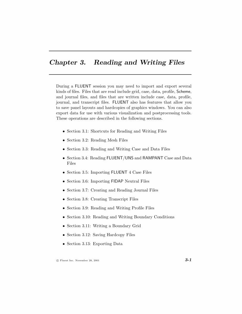
Chapter 3. Reading and Writing Files
During a FLUENT session you may need to import and export severalkinds of files. Files that are read include grid, case, data, profile, Scheme,and journal files, and files that are written include case, data, profile,journal, and transcript files. FLUENT also has features that allow youto save panel layouts and hardcopies of graphics windows. You can alsoexport data for use with various visualization and postprocessing tools.These operations are described in the following sections.
• Section 3.1: Shortcuts for Reading and Writing Files
• Section 3.2: Reading Mesh Files
• Section 3.3: Reading and Writing Case and Data Files
• Section 3.4: Reading FLUENT/UNS and RAMPANT Case and DataFiles
• Section 3.5: Importing FLUENT 4 Case Files
• Section 3.6: Importing FIDAP Neutral Files
• Section 3.7: Creating and Reading Journal Files
• Section 3.8: Creating Transcript Files
• Section 3.9: Reading and Writing Profile Files
• Section 3.10: Reading and Writing Boundary Conditions
• Section 3.11: Writing a Boundary Grid
• Section 3.12: Saving Hardcopy Files
• Section 3.13: Exporting Data
c© Fluent Inc. November 28, 2001 3-1

Reading and Writing Files
• Section 3.14: Grid-to-Grid Solution Interpolation
• Section 3.15: Loading Scheme Source Files
• Section 3.16: The .fluent File
• Section 3.17: Saving the Panel Layout
• Section 3.18: Formats of FLUENT Case and Data Files
3.1 Shortcuts for Reading and Writing Files
FLUENT has several features that make the reading and writing of filesvery convenient:
• Automatic appending or detection of default filename suffixes
• Binary file reading and writing
• Automatic detection of file format (text/binary)
• Recent file list
• Reading and writing of compressed files
• Tilde expansion
• Automatic numbering of files
• Ability to disable the overwrite confirmation prompt
3.1.1 Default File Suffixes
There are default file suffixes associated with each type of file that FLU-ENT reads or writes. For several commonly used files, the solver willautomatically append or detect the appropriate suffix when you spec-ify the first part of the filename (the prefix). For example, to write acase file named myfile.cas, you can specify just myfile and FLUENTwill automatically append .cas. Similarly, to read the case file namedmyfile.cas into the solver, you can specify just myfile and FLUENTwill automatically search for a file of that name with the suffix .cas.
3-2 c© Fluent Inc. November 28, 2001

3.1 Shortcuts for Reading and Writing Files
FLUENT will automatically append and detect default suffixes for caseand data files. In addition, FLUENT will automatically do this for PDFfiles and ray files. The appropriate default file suffix will appear in theSelect File dialog box for each type of file.
3.1.2 Binary Files
When you write a case, data, or ray file, FLUENT will save a binary fileby default. Binary files take up less space than text files and can be readand written by FLUENT more quickly. Note, however, that you cannotread and edit a binary file, as you can do for a text file. If you need tosave a text file, turn off the Write Binary Files option in the Select Filedialog box when you are writing the file.
FLUENT can read binary files that were saved on different platforms, but!other products, such as TGrid, cannot. If you are planning to read a casefile into TGrid on a different platform, you should save a text file fromFLUENT.
3.1.3 Detecting File Format
When you read a case, data, grid, PDF, or ray file, the solver will auto-matically determine whether it is a text (formatted) or binary file.
3.1.4 Recent File List
There is a shortcut for reading in case and data files that you haverecently used in FLUENT. At the bottom of the File/Read submenu thereis a list of the four FLUENT case files that you most recently read orwrote. To read one of these files into FLUENT, simply select it in thelist. This shortcut allows you to conveniently read a recently-used filewithout having to select it in the Select File dialog box.
Note that the files listed are the four case files that you have used mostrecently in any FLUENT session, so some may not be appropriate foryour current session (e.g., a 3D case file will be listed even if you arerunning a 2D version of FLUENT). Also, if you read a case file using thisshortcut, the corresponding data file will be read only if it has the samebase name as the case file (e.g., file1.cas and file1.dat) and it was
c© Fluent Inc. November 28, 2001 3-3

Reading and Writing Files
read (or written) with the case file the last time the case file was read(or written).
3.1.5 Reading and Writing Compressed Files
Reading Compressed Files
You can use the Select File dialog box to read files that have been com-pressed using compress or gzip. If you select a compressed file with a .Zextension, FLUENT will automatically invoke zcat to import the file’sdata. If you select a compressed file with a .gz extension, the solver willinvoke gunzip to import the file’s data.
For example, if you select a file named flow.msh.gz, the solver willreport the following message,
Reading "| gunzip -c flow.msh.gz"...
indicating that the result of the gunzip is imported into FLUENT via anoperating system pipe.
You can also type in the filename without any suffix (e.g., if you arenot sure whether or not the desired file is compressed). First, the solverattempts to open a file with the input name. If it cannot find a file withthat name, it attempts to locate files with default suffixes and extensionsappended to the name. For example, if you enter the name file-name,the solver traverses the following list until it finds an existing file:
• file-name
• file-name.gz
• file-name.Z
• file-name.suffix
• file-name.suffix.gz
• file-name.suffix.Z
3-4 c© Fluent Inc. November 28, 2001

3.1 Shortcuts for Reading and Writing Files
where suffix is a common extension to the file, such as .cas or .msh.The solver reports an error if it fails to find an existing file with one ofthese names.
For Windows systems, only files that were compressed with gzip (i.e.,!files with a .gz extension) can be read. Files that were compressed withcompress cannot be read into FLUENT on a Windows machine.
Do not read a compressed ray file; FLUENT will not be able to access!the ray tracing information properly from a compressed ray file.
Writing Compressed Files
You can use the Select File dialog box to write a compressed file byappending a .Z or .gz extension onto the file name.
For example, if you enter flow.gz as the name for a case file, the solverwill report the following message:
Writing "| gzip -cfv > flow.cas.gz"...
The status message indicates that the case file information is being pipedinto the gzip command, and that the output of the compression com-mand is being redirected to the file with the specified name. In thisparticular example, the .cas extension was added automatically.
For Windows systems, compression can be performed only with gzip;!that is, you can write a compressed file by appending .gz to the name,but appending .Z will not result in file compression.
Do not write a compressed ray file; FLUENT will not be able to access!the ray tracing information properly from a compressed ray file.
3.1.6 Tilde Expansion (UNIX Systems Only)
On UNIX systems, if you specify ~/ as the first two characters of afilename, the ~ will be expanded to be your home directory. Similarly,you can start a filename with ~username/, and the ~username will beexpanded to the home directory of “username”. If you specify ~/file
c© Fluent Inc. November 28, 2001 3-5

Reading and Writing Files
as the case file to be written, FLUENT will save the file file.cas inyour home directory. You can specify a subdirectory of your home di-rectory as well: if you enter ~/cases/file.cas, FLUENT will save thefile file.cas in the cases subdirectory.
3.1.7 Automatic Numbering of Files
There are several special characters that you can include in a filename.Using one of these character strings in your filename provides a short-cut for numbering the files based on various parameters (i.e., iterationnumber, time step, or total number of files saved so far), because youwill not need to enter a new filename each time you save a file. (See alsoSection 3.3.4 for information about saving and numbering case and datafiles automatically.)
• For unsteady calculations, you can save files with names that re-flect the time step at which they are saved by including the char-acter string %t in the file name. For example, you can specifycontours-%t.ps for the file name, and the solver will save a filewith the appropriate name (e.g., contours-0001.ps if the solutionis at the first time step).
• To save a file with a name that reflects the iteration at which it issaved, use the character string %i in the file name. For example,you can specify contours-%i.ps for the file name, and the solverwill save a file with the appropriate name (e.g., contours-0010.psif the solution is at the 10th iteration).
• To save a hardcopy file with a name that reflects the total numberof hardcopy files saved so far in the current solver session, use thecharacter string %n in the file name.
This option can be used only for hardcopy files.
Note that when you use the character strings described above in a file-!name, you will not be prompted for confirmation before FLUENT over-writes an existing file with the same name. Say, for example, that youare repeatedly using the filename myfile-%t.ps to save hardcopies with
3-6 c© Fluent Inc. November 28, 2001

3.2 Reading Mesh Files
names that reflect the current time step. If you have already savedmyfile-0001.ps at the first time step and then you restart the calcula-tion and save another hardcopy at the (new) first time step, the solverwill overwrite the original myfile-0001.ps without checking with youfirst.
3.1.8 Disabling the Overwrite Confirmation Prompt
By default, if you ask FLUENT to write a file with the same name as anexisting file in that directory, it will ask you to confirm that it is “OKto overwrite” the existing file. If you do not want the solver to ask youfor confirmation before it overwrites existing files, you can choose thefile/confirm-overwrite? text command and answer no.
3.2 Reading Mesh Files
Mesh files, also known as grid files, are created with the GAMBIT, TGrid,GeoMesh, and preBFC grid generators, or by several third-party CADpackages. A grid file is—from FLUENT’s point of view—simply a subsetof a case file (described in Section 3.3.1). The grid file contains thecoordinates of all the nodes, connectivity information that tells how thenodes are connected to one another to form faces and cells, and thezone types and numbers (e.g., wall-1, pressure-inlet-5, symmetry-2) ofall the faces. The grid file does not contain any boundary conditions,flow parameters, or solution parameters. For more information aboutgrids, see Chapter 5.
To read a native-format mesh file (i.e., a mesh file that has been saved inFLUENT format) into the solver, use the File/Read/Case... menu item,as described in Section 3.3.1. GAMBIT, TGrid, GeoMesh, and preBFC canall write a native-format mesh file. For more information about readingthese files, see Sections 5.3.1, 5.3.2, 5.3.3, and 5.3.4.
For information on importing an unpartitioned mesh file into the parallelsolver using the partition filter, see Section 28.4.4.
c© Fluent Inc. November 28, 2001 3-7
Reading and Writing Files
3.2.1 Reading TGrid Mesh Files
Since TGrid has the same file format as FLUENT, you can read a TGridmesh into the solver using the File/Read/Case... menu item.
File −→ Read −→Case...
For more information about reading TGrid mesh files, see Section 5.3.3.
3.2.2 Reading and Importing GAMBIT and GeoMesh Mesh Files
If you create a FLUENT 5/6, FLUENT/UNS, or RAMPANT grid in GAM-BIT or GeoMesh, you can read it into FLUENT using the File/Read/Case...menu item.
File −→ Read −→Case...
Selecting the Case... menu item will open the Select File dialog box (seeSection 2.1.2), in which you will specify the name of the file to be read.
If you have saved a neutral file from GAMBIT, rather than a FLUENTgrid file, you can import it into FLUENT using the File/Import/GAMBIT...menu item.
File −→ Import −→GAMBIT...
For more information about importing files from GAMBIT and GeoMesh,see Sections 5.3.1 and 5.3.2.
3.2.3 Reading preBFC Unstructured Mesh Files
Since preBFC’s unstructured triangular grids have the same file formatas FLUENT, you can read a preBFC triangular mesh into the solver usingthe File/Read/Case... menu item.
Note that you must save the file using the MESH-RAMPANT/TGRID com-!mand.
File −→ Read −→Case...
For more information about reading preBFC mesh files, see Section 5.3.4.
3-8 c© Fluent Inc. November 28, 2001

3.2 Reading Mesh Files
3.2.4 Importing preBFC Structured Mesh Files
You can read a preBFC structured mesh file into FLUENT using theFile/Import/preBFC Structured Mesh... menu item.
File −→ Import −→preBFC Structured Mesh...
Selecting the preBFC Structured Mesh... menu item will invoke the SelectFile dialog box (see Section 2.1.2), in which you will specify the nameof the preBFC structured mesh file to be read. The solver will readgrid information and zone types from the preBFC mesh file. For moreinformation about importing preBFC mesh files, see Section 5.3.4.
3.2.5 Importing ANSYS Files
To read an ANSYS file, use the File/Import/ANSYS... menu item.
File −→ Import −→ANSYS...
Selecting this menu item will invoke the Select File dialog box (see Sec-tion 2.1.2), in which you will specify the name of the ANSYS file to beread. The solver will read grid information from the ANSYS file. Formore information about importing ANSYS files, see Section 5.3.6.
3.2.6 Importing I-DEAS Universal Files
I-DEAS Universal files can be read into FLUENT with the File/Import/IDEASUniversal... menu item.
File −→ Import −→IDEAS Universal...
Selecting the IDEAS Universal... menu item will invoke the Select Filedialog box (see Section 2.1.2), in which you will specify the name of theI-DEAS Universal file to be read. The solver will read grid informationand zone types from the I-DEAS Universal file. For more informationabout importing I-DEAS Universal files, see Section 5.3.6.
3.2.7 Importing NASTRAN Files
NASTRAN files can be read into FLUENT with the File/Import/NASTRAN...menu item.
c© Fluent Inc. November 28, 2001 3-9

Reading and Writing Files
File −→ Import −→NASTRAN...
Selecting the NASTRAN... menu item will invoke the Select File dialogbox (see Section 2.1.2), in which you will specify the name of the NAS-TRAN file to be read. The solver will read grid information from theNASTRAN file. For more information about importing NASTRAN files,see Section 5.3.6.
3.2.8 Importing PATRAN Neutral Files
To read a PATRAN Neutral file zoned by named components (that is,a file in which you have grouped nodes with the same specified groupname), use the File/Import/PATRAN... menu item.
File −→ Import −→PATRAN...
Selecting this menu item will invoke the Select File dialog box (see Sec-tion 2.1.2), in which you will specify the name of the PATRAN Neutral fileto be read. The solver will read grid information from the PATRAN Neu-tral file. For more information about importing PATRAN Neutral files,see Section 5.3.6.
3.2.9 Importing Meshes and Data in CGNS Format
You can import meshes in CGNS (CFD general notation system) formatinto FLUENT using the File/Import/CGNS/Mesh... menu item.
File −→ Import −→ CGNS −→Mesh...
Note that this feature is available on a limited number of platforms (listedin the release notes).
To import a mesh and the corresponding CGNS data, you can use theFile/Import/CGNS/Mesh & Data... menu item.
File −→ Import −→ CGNS −→Mesh & Data...
3.2.10 Reading a New Grid File
After you have set up a case file using a particular grid, you can mergea new grid with the existing boundary conditions, material properties,
3-10 c© Fluent Inc. November 28, 2001

3.2 Reading Mesh Files
solution parameters, etc. One situation in which you might use thisfeature is if you have generated a better mesh for a problem you havebeen working on, and you do not want to reenter all of the boundaryconditions, properties, and parameters. You can read in the new grid aslong as it has the same zone structure as the original grid.
The new and original grids should have the same zones, numbered in the!same order. A warning is issued if they do not, because inconsistenciescould create problems with the boundary conditions.
New grids are read using the file/reread-grid command in the textinterface.
file −→reread-grid
c© Fluent Inc. November 28, 2001 3-11

Reading and Writing Files
3.3 Reading and Writing Case and Data Files
Information related to your FLUENT simulation is stored in two files: thecase file and the data file. The commands for reading and writing thesefiles are described in the following sections, along with commands for theautomatic saving of case and data at specified intervals. A descriptionof the case and data file formats is provided in Section 3.18.
• Section 3.3.1: Reading and Writing Case Files
• Section 3.3.2: Reading and Writing Data Files
• Section 3.3.3: Reading and Writing Case and Data Files Together
• Section 3.3.4: Automatic Saving of Case and Data Files
Note that FLUENT can read and write either text or binary case anddata files; binary files require less storage space and are faster to readand write. To specify whether to write a binary or text file, use the WriteBinary Files check button in the Select File dialog box (see Section 2.1.2).In addition, you can read and write either text or binary files in com-pressed formats (see Section 3.1.5). FLUENT automatically detects thefile type when reading.
If you adapt the grid, you must save a new case file as well as a data file.!Otherwise the new data file will not correspond to the case file (they willhave different numbers of cells, for example). FLUENT will warn youwhen you try to exit the program if you have not saved an up-to-datecase or data file.
3.3.1 Reading and Writing Case Files
Case files contain the grid, boundary conditions, and solution parame-ters for a problem, as well as information about the user interface andgraphics environment. For information about the format of case files seeSection 3.18. The commands used for reading case files can also be usedto read native-format grid files (as described in Section 3.2) because thegrid information is a subset of the case information.
3-12 c© Fluent Inc. November 28, 2001

3.3 Reading and Writing Case and Data Files
You can read a case file using the Select File dialog box (see Section 2.1.2)invoked by selecting the File/Read/Case... menu item. To write a casefile, use the Select File dialog box invoked by selecting the File/Write/Case...menu item.
File −→ Read −→Case...
File −→ Write −→Case...
See Section 1.5.2 for information about executing the appropriate versionautomatically based on the case file that is read.
Default Suffixes
By convention, case file names are composed of a root with the suffix.cas. If you conform to this convention, you do not have to type thesuffix when prompted for a filename; it will be added automatically.When FLUENT reads a case file, it first looks for a file with the exactname you typed. If a file with that name is not found, it uses theprocedure described in Section 3.1.5 to search for the case file. WhenFLUENT writes a case file, .cas will be added to the name you typeunless the name already ends with .cas.
3.3.2 Reading and Writing Data Files
Data files contain the values of the flow field in each grid element andthe convergence history (residuals) for that flow field. For informationabout the format of data files see Section 3.18.
You can read a data file using the Select File dialog box (see Section 2.1.2)invoked by selecting the File/Read/Data... menu item. Likewise, you canwrite a data file using the Select File dialog box invoked by selecting theFile/Write/Data... menu item.
File −→ Read −→Data...
File −→ Write −→Data...
c© Fluent Inc. November 28, 2001 3-13

Reading and Writing Files
Default Suffixes
By convention, data file names are composed of a root with the suffix.dat. If you conform to this convention, you do not have to type thesuffix when prompted for a filename; it will be added automatically.When FLUENT reads a data file, it first looks for a file with the exactname you typed. If a file with that name is not found, it uses theprocedure described in Section 3.1.5 to search for the data file. When itwrites a data file, .dat will be added to the name you type unless thename already ends with .dat.
3.3.3 Reading and Writing Case and Data Files Together
A case file and a data file together contain all the information requiredto restart a solution. Case files contain the grid, boundary conditions,and solution parameters. Data files contain the values of the flow field ineach grid element and the convergence history (residuals) for that flowfield.
You can read a case file and a data file together by using the Select Filedialog box (see Section 2.1.2) invoked by selecting the File/Read/Case &Data... menu item. To read both files, select the appropriate case file,and the corresponding data file (same name with .dat suffix) will alsobe read. To write a case file and a data file, select the File/Write/Case& Data... menu item.
File −→ Read −→Case & Data...
File −→ Write −→Case & Data...
See Section 1.5.2 for information about executing the appropriate versionautomatically based on the case file that is read.
3.3.4 Automatic Saving of Case and Data Files
You can request FLUENT to automatically save case and data files atspecified intervals during a calculation. This is especially useful for time-dependent calculations, since it will allow you to save the results atdifferent time steps without stopping the calculation and performing thesave manually. You can also use the auto-save feature for steady-state
3-14 c© Fluent Inc. November 28, 2001

3.3 Reading and Writing Case and Data Files
problems, to examine the solution at different stages in the iterationhistory.
Automatic saving is specified using the Autosave Case/Data panel (Fig-ure 3.3.1).
File −→ Write −→Autosave...
Figure 3.3.1: The Autosave Case/Data Panel
You must set the frequency of saves for case and/or data files, and theroot filename. Enter the case-saving frequency in the Autosave Case FileFrequency field, and the data-saving frequency in the Autosave Data FileFrequency field. Both values are set to zero by default, indicating thatno automatic saving is performed.
For steady flows you will specify the frequency in iterations, and forunsteady flows you will specify it in time steps (unless you are usingthe explicit time stepping formulation, in which case you will specify thefrequency in iterations). If you define an Autosave Case File Frequencyof 10, for example, a case file will be saved every 10 iterations or timesteps.
Enter the filename to be used for the autosave files in the Filename field.The iteration or time-step number and an appropriate suffix (.cas or.dat) will be added to the specified root name. If the specified Filenameends in .gz or .Z, appropriate file compression will be performed. (SeeSection 3.1.5 for details about file compression.)
c© Fluent Inc. November 28, 2001 3-15

Reading and Writing Files
All of the autosave inputs are stored in the case file.
3.4 Reading FLUENT/UNS and RAMPANT Case and DataFiles
Case files created by FLUENT/UNS 3 or 4 or RAMPANT 2, 3, or 4 can beread into FLUENT in the same way that current case files are read (seeSection 3.3). If you read a case file created by FLUENT/UNS, FLUENTwill select the Segregated solver in the Solver panel. If you read a casefile created by RAMPANT, FLUENT will select the Coupled Explicit solverformulation in the Solver panel.
Data files created by FLUENT/UNS 4 or RAMPANT 4 can be read intoFLUENT in the same way that current data files are read (see Sec-tion 3.3).
3.5 Importing FLUENT 4 Case Files
You can read a FLUENT 4 case file using the File/Import/FLUENT 4Case... menu item.
File −→ Import −→FLUENT 4 Case...
Selecting the FLUENT 4 Case... menu item will invoke the Select Filedialog box (see Section 2.1.2), in which you will specify the name of theFLUENT 4 case file to be read. FLUENT will read only grid informa-tion and zone types from the FLUENT 4 case file. You must specifyboundary conditions, model parameters, material properties, and otherinformation after reading this file. For more information about importingFLUENT 4 case files, see Section 5.3.8.
3.6 Importing FIDAP Neutral Files
You can read a FIDAP Neutral file using the File/Import/FIDAP... menuitem.
File −→ Import −→FIDAP...
Selecting the FIDAP... menu item will invoke the Select File dialog box(see Section 2.1.2), in which you will specify the name of the FIDAP file
3-16 c© Fluent Inc. November 28, 2001

3.7 Creating and Reading Journal Files
to be read. FLUENT will read grid information and zone types from theFIDAP file. You must specify boundary conditions and other informationafter reading this file. For more information about importing FIDAPNeutral files, see Section 5.3.9.
3.7 Creating and Reading Journal Files
A journal file contains a sequence of FLUENT commands, arranged asthey would be typed interactively into the program or entered throughthe GUI. GUI commands are recorded as Scheme code lines in journalfiles. FLUENT creates a journal file by recording everything you type onthe command line or enter through the GUI. You may also create journalfiles manually with a text editor. If you want to include comments inyour file, be sure to put a ; (semicolon) at the beginning of each commentline. See Section 2.5.1 for an example.
The purpose of a journal file is usually to automate a series of commandsrather than entering them repeatedly on the command line. Anotheruse is to produce a record of the input to a program session for laterreference, although transcript files are often more useful for this purpose(see Section 3.8).
Command input is taken from the specified journal file until its end isreached, at which time control is returned to the standard input (usuallythe keyboard). Each line from the journal file is echoed to the standardoutput (usually the screen) as it is read and processed.
Since a journal file is, by design, just a simple record/playback facility,!it knows nothing about the state in which it was recorded or the statein which it is being played back. You should, therefore, try to recreatethe state in which the journal was written before you read it into theprogram. If, for example, your journal file includes an instruction forFLUENT to save a new file with a specified name, you should check thatno file with that name exists in your directory before you read in yourjournal file. If a file with that name does exist and you read in yourjournal file anyway, when the program reaches the write instruction,it will prompt for a confirmation that it is OK to overwrite the oldfile. Since no response to the confirmation request is contained in thejournal file, FLUENT will not be able to continue following the journal’s
c© Fluent Inc. November 28, 2001 3-17

Reading and Writing Files
instructions. Other conditions that may affect the program’s ability toperform the instructions contained in a journal file can be created bymodifications or manipulations that you make within the program. Forexample, if your journal file creates several surfaces and displays data onthose surfaces, you must be sure to read in appropriate case and datafiles before reading the journal file.
Only one journal file can be open for recording at a time, but you can!write a journal and a transcript file simultaneously. You can also read ajournal file at any time.
3.7.1 User Inputs
To start the journaling process, select the File/Write/Start Journal...menu item.
File −→ Write −→Start Journal...
After you enter a name for the file in the Select File dialog box (seeSection 2.1.2), journal recording will begin and the Start Journal... menuitem will become the Stop Journal menu item. You can end journalrecording by selecting Stop Journal, or simply by exiting the program.
File −→ Write −→Stop Journal
You can read a journal file into the program using the Select File dialogbox invoked by selecting the File/Read/Journal... menu item.
File −→ Read −→Journal...
Journal files are always loaded in the main (i.e., top-level) text menu,regardless of where you are in the text menu hierarchy when you invokethe read command.
3-18 c© Fluent Inc. November 28, 2001

3.8 Creating Transcript Files
3.8 Creating Transcript Files
A transcript file contains a complete record of all standard input to andoutput from FLUENT (usually all keyboard and GUI input and all screenoutput). GUI commands are recorded as Scheme code lines in transcriptfiles. FLUENT creates a transcript file by recording everything typed asinput or entered through the GUI, and everything printed as output inthe text window.
The purpose of a transcript file is to produce a record of the programsession for later reference. Because they contain messages and otheroutput, transcript files, unlike journal files (see Section 3.7), cannot beread back into the program.
Only one transcript file can be open for recording at a time, but you can!write a transcript and a journal file simultaneously. You can also read ajournal file while a transcript recording is in progress.
3.8.1 User Inputs
To start the transcripting process, select the File/Write/Start Transcript...menu item.
File −→ Write −→Start Transcript...
After you enter a name for the file in the Select File dialog box (seeSection 2.1.2), transcript recording will begin and the Start Transcript...menu item will become the Stop Transcript menu item. You can endtranscript recording by selecting Stop Transcript, or simply by exitingthe program.
File −→ Write −→Stop Transcript
c© Fluent Inc. November 28, 2001 3-19
Reading and Writing Files
3.9 Reading and Writing Profile Files
Boundary profiles are used to specify flow conditions on a boundaryzone of the solution domain. For example, they can be used to prescribea velocity field on an inlet plane. For more information on boundaryprofiles, see Section 6.25.
Reading Profile Files
Boundary profile files can be read using the Select File dialog box invokedby selecting the File/Read/Profile... menu item.
File −→ Read −→Profile...
Writing Profile Files
You can also create a profile file from the conditions on a specified bound-ary or surface. For example, you can create a profile file from the outletconditions of one case and then read that profile into another case anduse the outlet profile data as the inlet conditions for the new case.
To write a profile file, you will use the Write Profile panel (Figure 3.9.1).
File −→ Write −→Profile...
1. Retain the default option of Define New Profiles.
2. Select the surface(s) from which you want to extract data for theprofile(s) in the Surfaces list.
3. Choose the variable(s) for which you want to create profiles in theValues list.
4. Click on the Write... button and specify the profile file name in theresulting Select File dialog box.
FLUENT will save the grid coordinates of the data points in the selectedsurface(s) and the values of the selected variables at those positions.When you read the profile file back into the solver, the “surface” name
3-20 c© Fluent Inc. November 28, 2001

3.9 Reading and Writing Profile Files
Figure 3.9.1: The Write Profile Panel
will be the profile name and the “value” name will be the field name thatappears in the drop-down lists in the boundary condition panels.
If you have made any modifications to the boundary profiles since youread them in (e.g., if you reoriented an existing profile to create a newone), or if you wish to store all the profiles used in a case file in a separatefile, you can simply select the Write Currently Defined Profiles option andclick on the Write... button. All currently defined profiles will be savedin the file you specify in the resulting Select File dialog box. This filecan be read back into the solver whenever you wish to use these profilesagain.
c© Fluent Inc. November 28, 2001 3-21

Reading and Writing Files
3.10 Reading and Writing Boundary Conditions
To save all currently-defined boundary conditions to a file, select thewrite-bc text command and specify a name for the file.
file −→write-bc
FLUENT will write the boundary condition to a file, using the sameformat as the “zone” section of the case file. See Section 3.18 for detailsabout the case file format.
To read boundary conditions from a file and apply them to the corre-sponding zones in your model, select the read-bc text command.
file −→read-bc
FLUENT will set the boundary conditions in the current model by com-paring the zone name associated with each set of conditions in the filewith the zone names in the model. If the model does not contain amatching zone name for a set of boundary conditions, those conditionswill be ignored.
If you read boundary conditions into a model that contains a different!mesh topology (e.g., a cell zone has been removed), you should checkthe conditions at boundaries within and adjacent to the region of thetopological change. This is particularly important for wall zones.
If you want FLUENT to apply a set of conditions to multiple zones withsimilar names, or to a single zone with a name you’re not completelysure of in advance, you can edit the boundary-condition file you savedwith the write-bc command to include “wildcards” (*) within the zonenames. For example, if you want to apply a particular set of conditionsto wall-12, wall-15, and wall-17 in your current model, you shouldedit the boundary-condition file so that the zone name associated withthe desired conditions is wall-*.
3-22 c© Fluent Inc. November 28, 2001

3.11 Writing a Boundary Grid
3.11 Writing a Boundary Grid
You can write the boundary zones (surface grid) to a file. This file canbe read and used by TGrid to produce a volume mesh. You may find thisfeature useful if you are unsatisfied with a mesh that you obtained fromanother grid generation program.
A boundary grid can be written using the Select File dialog box (seeSection 2.1.2) invoked by selecting the File/Write/Boundary Grid... menuitem.
File −→ Write −→Boundary Grid...
3.12 Saving Hardcopy Files
Graphics window displays can be saved in various formats, includingTIFF, PICT, and PostScript. There may be slight differences, however,between hardcopies and the displayed graphics windows, since hardcopiesare generated using the internal software renderer, while the graphicswindows may utilize specialized graphics hardware for optimum perfor-mance. Many systems provide a utility to “dump” the contents of agraphics window into a raster file. This is generally the fastest methodof generating a hardcopy (since the scene is already rendered in thegraphics window), and guarantees that the hardcopy will be identical tothe window.
3.12.1 Using the Graphics Hardcopy Panel
To set hardcopy parameters and save hardcopy files, you will use theGraphics Hardcopy panel (Figure 3.12.1).
File −→Hardcopy...
The procedure for saving a hardcopy file is listed below, followed bydetails about each step.
1. Choose the hardcopy file format.
2. (optional) Specify the file type, if applicable.
c© Fluent Inc. November 28, 2001 3-23

Reading and Writing Files
Figure 3.12.1: The Graphics Hardcopy Panel
3. Set the coloring.
4. (optional) Define the resolution, if applicable.
5. Set any of the options described below.
6. If you are generating a window dump, specify the command to beused for the dump.
7. (optional) Preview the result.
8. Click on the Save... button and enter the filename in the resultingSelect File dialog box. (See Section 3.1.7 for information on specialfeatures related to filename specification.)
If you want to save the current hardcopy settings, but you are not readyto save a hardcopy yet, you can click on the Apply button instead ofthe Save... button. The applied settings will become the defaults forsubsequent hardcopies.
3-24 c© Fluent Inc. November 28, 2001

3.12 Saving Hardcopy Files
Choosing the Hardcopy File Format
To choose the hardcopy file format, select one of the following items inthe Format list:
EPS (Encapsulated PostScript) output is the same as PostScript output,with the addition of Adobe Document Structuring Conventions(v2) statements. Currently, no preview bitmap is included in EPSoutput. Often, programs that import EPS files use the previewbitmap to display on-screen, although the actual vector PostScriptinformation is used for printing (on a PostScript device). You cansave EPS files in raster or vector format.
HPGL is a vector file format designed for pen plotters. The HPGL driversupports a limited set of colors and is not capable of rendering somescenes properly.
IRIS Image is the native raster image file format on SGI computers. TheIRIS Image driver may not be available on all platforms.
JPEG is a common raster file format.
PICT is the native graphics file format on Macintosh computers. PICTfiles may contain either vector or raster information (or both).Typically, “draw” programs generate vector information, while“paint” programs use raster formats. You can choose to save aPICT file in raster or vector format.
PPM output is a common raster file format.
PostScript is a common vector file format. You can also choose to savea PostScript file in raster format.
TIFF is a common raster file format.
VRML is a graphics interchange format that allows export of 3D ge-ometrical entities that you can display in the FLUENT graphicswindow. This format can commonly be used by VR systems andin particular the 3D geometry can be viewed and manipulated ina web-browser graphics window.
c© Fluent Inc. November 28, 2001 3-25
Reading and Writing Files
Note that non-geometric entities such as text, titles, color bars,!and orientation axis are not exported. In addition, most display orvisibility characteristics set in FLUENT, such as lighting, shadingmethod, transparency, face and edge visibility, outer face culling,and hidden line removal, are not explicitly exported but are con-trolled by the software used to view the VRML file.
Window Dump (UNIX systems only) selects a window dump operationfor generating the hardcopy. With this format, you will need tospecify the appropriate Window Dump Command. See below fordetails.
Choosing the File Type
If you are saving a PostScript, EPS (Encapsulated PostScript), or PICTfile, you can choose Raster or Vector as the File Type. A vector file definesthe graphics image as a combination of geometric primitives like lines,polygons, and text. A raster file defines the color of each individual pixelin the image. Vector files are usually scalable to any resolution, whileraster files have a fixed resolution. Supported vector formats includePostScript, EPS, HPGL, and PICT. Supported raster formats are IRISimage, JPEG, PICT, PPM, PostScript, EPS, and TIFF.
In general, for the quickest print time, you may want to save vector files!for simple 2D displays and raster files for complicated scenes.
Specifying the Color Mode
For all formats except the window dump you can specify which type ofColoring you want to use for the hardcopy file. For a color-scale copyselect Color, for a gray-scale copy select Gray Scale, and for a black-and-white copy, select Monochrome. Note that most monochrome PostScriptdevices will render Color images in shades of gray, but to ensure that thecolor ramp is rendered as a linearly-increasing gray ramp, you shouldselect Gray Scale.
3-26 c© Fluent Inc. November 28, 2001

3.12 Saving Hardcopy Files
Defining the Resolution
For raster hardcopy files, you can control the resolution of the hardcopyimage by specifying the size (in pixels). Set the desired Width and Heightunder Resolution. If the Width and Height are both zero, the hardcopyis generated at the same resolution as the active graphics window. (Tocheck the size of the active window in pixels, you can click on Info in theDisplay Options panel.)
Note that for PostScript, EPS, and PICT files, you will specify the res-olution in dots per inch (DPI) instead of setting the width and height.
Hardcopy Options
For all hardcopy formats except the window dump, you can control twoadditional settings under Options. First, you can specify the orientationof the hardcopy using the Landscape Orientation button. If this option isturned on, the hardcopy is made in landscape mode; otherwise, it is madein portrait mode. Second, you can control the foreground/backgroundcolor using the Reverse Foreground/Background option. If this optionis enabled, the foreground and background colors of graphics windowsbeing hardcopied will be swapped. This feature allows you to makehardcopies with a white background and a black foreground, while thegraphics windows are displayed with a black background and white fore-ground.
Hardcopy Options for PostScript Files
FLUENT provides options that allow you to save PostScript files thatcan be printed more quickly. The following options can be found in thedisplay/set/hardcopy/driver/post-format text menu:
fast-raster enables a raster file that may be larger than the standardraster file, but will print much more quickly.
raster enables the standard raster file.
rle-raster enables a run-length encoded raster file that will be aboutthe same size as the standard raster file, but will print slightly more
c© Fluent Inc. November 28, 2001 3-27

Reading and Writing Files
quickly. (This is the default file type.)
vector enables the standard vector file.
(Vector and raster files are described above.)
Window Dumps (UNIX Systems Only)
If you select the Window Dump format, the program will use the specifiedWindow Dump Command to save the hardcopy file. For example, if youwant to use xwd to capture a window, you will set the Window DumpCommand to
xwd -id %w >
FLUENT will automatically interpret %w to be the ID number of theactive window when the dump occurs. In the Select File dialog box thatappears when you click on the Save... button, enter the filename for theoutput from the window dump (e.g., myfile.xwd).
If you are planning to make an animation, you might want to save thewindow dumps into numbered files, using the %n variable. To do this,you will use the same Window Dump Command as that shown in theexample above, but for the filename in the Select File dialog box you willenter myfile%n.xwd. Each time you create a new window dump, thevalue of %n will increase by one, so you do not need to tack numbersonto the hardcopy filenames manually.
If you are planning to use the ImageMagick animate program, saving thefiles in MIFF format (the native ImageMagick format) is more efficient.In such cases, you should use the ImageMagick tool import. For theWindow Dump Command you will enter
import -window %w
(which is the default command). In the Select File dialog box that ap-pears when you click on the Save... button, specify the output format tobe MIFF by using the .miff suffix at the end of your filename.
3-28 c© Fluent Inc. November 28, 2001
3.13 Exporting Data
The window-dump feature is system- and graphics-driver-specific. Thusthe commands available to you for dumping windows will depend heavilyon your particular configuration.
Another issue to consider when saving window dumps is that the win-dow dump will capture the window exactly as it is displayed, includingresolution, colors, transparency, etc. (For this reason, all of the inputsthat control these characteristics are disabled in the Graphics Hardcopypanel when you enable the Window Dump format.) If you are using an8-bit graphics display, you might want to use one of the built-in rasterdrivers (e.g., TIFF) to generate higher-quality 24-bit color output ratherthan dumping the 8-bit window.
Previewing the Hardcopy Image
Before you save a hardcopy file, you have the option of previewing whatthe saved image will look like. If you click on Preview, the current settingsare applied to the active graphics window so that you can investigate theeffects of different options interactively before saving the final, approvedhardcopy.
3.13 Exporting Data
The current release of FLUENT allows you to export data to Abaqus,ANSYS, ASCII, AVS, CGNS, Data Explorer, EnSight (formerly known asMPGS), FAST, FIELDVIEW, I-DEAS, NASTRAN, PATRAN, and Tecplot.Section 3.13.1 explains how to save data in these formats, and Sec-tion 3.13.2 describes each type of file.
Note that, of these formats, only EnSight and FIELDVIEW case and datafiles can be exported using the parallel version of FLUENT.
If you intend to export data to I-DEAS, you should ensure that your mesh!does not contain pyramid elements, as these are currently not supportedby I-DEAS.
c© Fluent Inc. November 28, 2001 3-29
Reading and Writing Files
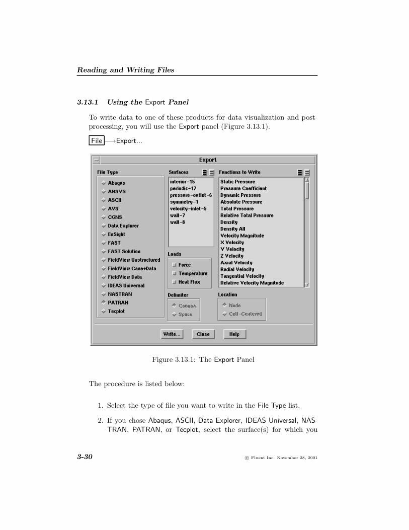
3.13.1 Using the Export Panel
To write data to one of these products for data visualization and post-processing, you will use the Export panel (Figure 3.13.1).
File −→Export...
Figure 3.13.1: The Export Panel
The procedure is listed below:
1. Select the type of file you want to write in the File Type list.
2. If you chose Abaqus, ASCII, Data Explorer, IDEAS Universal, NAS-TRAN, PATRAN, or Tecplot, select the surface(s) for which you
3-30 c© Fluent Inc. November 28, 2001

3.13 Exporting Data
want to write data in the Surfaces list. If no surfaces are selected,the entire domain is exported.
3. For all file types except ANSYS, FAST Solution, and NASTRAN,select the variable(s) for which data is to be saved in the Functionsto Write list.
4. (optional) For Abaqus, ASCII, IDEAS Universal, NASTRAN, andPATRAN files, select the Loads to be written (Force, Temperature,and/or Heat Flux). Saving these loads will allow you to analyze thestructural stresses (fluid pressure or thermal) in an FEA program.Note that loads are written only on boundary walls when the entiredomain is exported (i.e., if you select no Surfaces).
5. (optional) For ASCII files, select the Delimiter separating the fields(Comma or Space) and the Location from which the values of scalarfunctions are to be taken (Node values or Cell-Centered values).
6. Click on the Write... button to save a file for the specified func-tion(s) in the specified format, using the Select File dialog box.
3.13.2 Export File Formats
Below, the files that are written when you select each export file typeare listed:
Abaqus: a single file containing coordinates, connectivity, optional loads,zone groups, velocity, and selected scalars will be written. You canspecify which scalars you want in the Functions to Write list. Exportof data in solid zones to Abaqus is available for 3D models only.
ANSYS: a single file containing coordinates, connectivity, zone groups,velocity, pressure, temperature, and turbulence quantities will bewritten. The file written is an ANSYS results file with a .rflextension. Note that export to ANSYS is available on a limitednumber of platforms (listed in the release notes).
ASCII: a single ASCII file containing the coordinate and connectivityinformation and specified scalar function data.
c© Fluent Inc. November 28, 2001 3-31

Reading and Writing Files
AVS: an AVS version 4 UCD file containing coordinate and connectivityinformation and specified scalar function data.
CGNS (CFD general notation system): a single file containing coordi-nates, connectivity, velocity, and selected scalars will be written.You can specify which scalars you want in the Functions to Writelist.
Data Explorer: a single file containing coordinate, connectivity, velocity,and specified function data.
EnSight (formerly MPGS): a geometry file containing the coordinates andconnectivity information, a velocity file containing the velocity, ascalar file for each selected variable or function, and a results filelisting all the file names used.
FAST: a grid file in extended Plot3D format containing coordinates andconnectivity, a velocity file containing the velocity, and a scalar filefor each selected variable or function. This file type is valid onlyfor triangular and tetrahedral grids.
FAST Solution: a single file containing density, velocity, and total energy.This file type is valid only for triangular and tetrahedral grids.
FieldView Unstructured: a single binary file containing coordinate andconnectivity information and specified scalar function data. Thisfile type is valid only for 3D grids.
FieldView Case+Data: a FLUENT case file that can be read by FIELD-VIEW, and a data file containing node-averaged values for the se-lected variables.
FieldView Data: a data file containing node-averaged values for the se-lected variables. (For transient simulations, you will often exportmultiple FIELDVIEW data files but you will usually want to savethe case file just once. In such cases, you can use the FieldViewCase+Data option to save the first data set with a case file, andthen use the FieldView Data option to save subsequent data setswithout a case file.)
3-32 c© Fluent Inc. November 28, 2001

3.14 Grid-to-Grid Solution Interpolation
IDEAS Universal: a single file containing coordinates, connectivity, op-tional loads, zone groups, velocity, and selected scalars.
NASTRAN: a single file containing coordinates, connectivity, optionalloads, zone groups, and velocity. Pressure is written as PLOAD, andheat flux is written as QHBDY data. If wall zones are selected in theSurfaces list, nodal forces are written for the walls.
PATRAN: a single file containing coordinates, connectivity, optional loads,zone groups, velocity, and selected scalars. Pressure is written asa distributed load. If wall zones are selected in the Surfaces list,nodal forces are written for the walls. The PATRAN result tem-plate file is written. This file lists the scalars present in the nodalresult file (.rst).
Tecplot: a single file containing the coordinates and scalar functions inthe appropriate tabular format.
3.14 Grid-to-Grid Solution Interpolation
FLUENT can interpolate solution data for a given geometry from onegrid to another, allowing you to compute a solution using one grid (e.g.,hexahedral) and then change to another grid (e.g., hybrid) and continuethe calculation using the first solution as a starting point.
3.14.1 Performing Grid-to-Grid Solution Interpolation
The procedure for grid-to-grid solution interpolation is as follows:
1. Set up the model and calculate a solution on the initial grid.
2. Write an interpolation file for the solution data to be interpolatedonto the new grid, using the Interpolate Data panel (Figure 3.14.1).
File −→Interpolate...
(a) Under Options, select Write Data.
(b) In the Cell Zones list, select the cell zones for which you wantto save data to be interpolated.
c© Fluent Inc. November 28, 2001 3-33

Reading and Writing Files
Figure 3.14.1: The Interpolate Data Panel
If your case includes both fluid and solid zones, you will need!to write the data for the fluid zones and the data for the solidzones to separate files.
(c) Choose the variable(s) for which you want to interpolate datain the Fields list. All FLUENT solution variables are availablefor interpolation.
(d) Click on the Write... button and specify the interpolation filename in the resulting Select File dialog box. The file formatis described in Section 3.14.2.
3. If the new and original grids have the same zones, numbered in thesame order, simply read in the new grid.
file −→reread-grid
If the new and original grids have a different number of zones ortheir zones are numbered differently, you will need to set up a newcase:
3-34 c© Fluent Inc. November 28, 2001

3.14 Grid-to-Grid Solution Interpolation
(a) Read in the new grid, using the appropriate menu item in theFile/Read/ or File/Import/ menu.
(b) Define the appropriate models.
It is very important that you enable all of the models that!were enabled in the original case. If, for example, the energyequation was enabled in the original case and you forget toenable it in the new case, the temperature data in the inter-polation file will not be interpolated.
(c) Define the boundary conditions, material properties, etc.
4. Read in the data to be interpolated.
File −→Interpolate...
(a) Under Options, select Read and Interpolate.
(b) In the Cell Zones list, select the cell zones for which you wantto read and interpolate data.
Note that, if the solution has not been initialized, computed,or read, all zones in the Cell Zones list will be selected bydefault, to ensure that no zone remains without data afterthe interpolation. If all zones already have data (from initial-ization or a previously computed or read solution), you canselect a subset of the Cell Zones to read and interpolate dataonto a specific zone (or zones).
(c) Click on the Read... button and specify the interpolation filename in the resulting Select File dialog box.
If your case includes both fluid and solid zones, you will need to!perform these steps twice (once to interpolate the data for the fluidzones and once to interpolate the data for the solid zones), sincethe two sets of data were saved to separate files.
5. Lower the under-relaxation factors and calculate on the new gridfor a few iterations to avoid sudden changes due to any imbalanceof fluxes after interpolation. Then increase the under-relaxationfactors and compute a solution on the new grid.
c© Fluent Inc. November 28, 2001 3-35

Reading and Writing Files
3.14.2 Format of the Interpolation File
The format of the interpolation file is as follows:
• The first line is the interpolation file version. It is 1.0 for FLU-ENT 5 and 2.0 for FLUENT 6.
• The second line is the dimensionality (2 or 3).
• The third line is the total number of points.
• The fourth line is the total number of fields (temperature, pressure,etc.) included.
• A list of field names follows, from line 5. You can see a com-plete list of the field names used by FLUENT by selecting thedisplay/contours text command and viewing the available choicesfor contours of. The list depends on the models turned on.
• After the list of field names, comes a list of x, y, and (in 3D) zcoordinates for all the data points.
• All the field values at all the points in the same order as theirnames are listed last. The number of coordinate and field pointsshould match the number given in line 3.
An example is shown below:
22348003x-velocitypressurey-velocity-0.068062-0.0680413...
3-36 c© Fluent Inc. November 28, 2001

3.15 Reading Scheme Source Files
3.15 Reading Scheme Source Files
A Scheme source file can be loaded in three ways: through the menusystem as a scheme file, through the menu system as a journal file, orthrough Scheme itself.
For large source files you will normally use the Select File dialog box (seeSection 2.1.2) invoked by selecting the File/Read/Scheme... menu item
File −→ Read −→Scheme...
or the Scheme load function.
> (load "file.scm")
Shorter files can also be loaded with the File/Read/Journal... menu itemor the file/read-journal command in the text interface (or its . orsource alias).
> . file.scm
> source file.scm
In this case, each character of the file is echoed to the console as it isread in the same way as if you were typing the contents of the file in byhand.
3.16 The .fluent File
When starting up, FLUENT looks in your home directory for an optionalfile called .fluent. If it finds the file, it loads it with the Scheme loadfunction. This file can contain Scheme functions that customize thecode’s operation.
c© Fluent Inc. November 28, 2001 3-37

Reading and Writing Files
3.17 Saving the Panel Layout
The Save Layout command in the File pull-down menu allows you tosave the present panel and window layout. Specifically, you can arrangepanels and graphics windows on your screen in a preferred configurationand select the File/Save Layout menu item.
File −→Save Layout
A .cxlayout file is written in your home directory. (If you subsequentlyarrange different panels and save the layout again, the positions of thesepanels will be added to the positions of the panels that you saved earlier.If you move a panel for which a position is already saved, and thenyou save the layout, the new position will be written to the .cxlayoutfile.) In subsequent sessions, when you open a panel or create a graphicswindow, it will be positioned based on the saved configuration. Anypanel or window not specified in the saved configuration will use thedefault position. Note that the .cxlayout file in your home directoryapplies to all Cortex applications (i.e., FLUENT, FLUENT/Post, MixSim,and TGrid).
3-38 c© Fluent Inc. November 28, 2001

3.18 Formats of Case and Data Files
3.18 Formats of Case and Data Files
This section describes the contents and formats of FLUENT case anddata files. These files are broken into several sections according to thefollowing guidelines:
• Each section is enclosed in parentheses and begins with a decimalinteger indicating its type. This integer is different for formattedand binary files, as described in Section 3.18.1.
• All groups of items are enclosed in parentheses. This makes skip-ping to ends of (sub)sections and parsing them very easy. It alsoallows for easy and compatible addition of new items in futurereleases.
• Header information for lists of items is enclosed in separate setsof parentheses preceding the items, and the items are enclosed intheir own parentheses.
Descriptions of the sections are grouped according to function. If youare creating grids for FLUENT, you only need to consider the sectionsdescribed in Section 3.18.2. If you are attempting to import solutionsinto another postprocessor, you should study Sections 3.18.2 and 3.18.4.Section 3.18.3 describes the sections that store boundary conditions, ma-terial properties, and solver control settings. See Section 3.18.1 for detailsabout differences between formatted and binary files.
Note that the case and data files may contain other sections that areintended for internal use only.
3.18.1 Formatting Conventions in Binary and Formatted Files
For formatted files, examples of file sections are given in Sections 3.18.2and 3.18.3. For binary files, the header indices described in this section(e.g., 10 for the node section) are preceded by 20 for single-precisionbinary data, or by 30 for double-precision binary data (e.g., 2010 or3010 instead of 10). Also, the end of the binary data is indicated by Endof Binary Section 2010 or End of Binary Section 3010 before the
c© Fluent Inc. November 28, 2001 3-39

Reading and Writing Files
closing parameters of the section. An example is shown below (with thebinary data represented by periods):
(2010 (2 1 2aad 2 3)(...)End of Binary Section 2010)
3.18.2 Grid Sections
Grid sections are stored in the case file. (A “grid” file is a subset of a casefile, containing only those sections pertaining to the grid.) Following aredescriptions of the currently defined grid sections.
The section ID numbers are indicated below in both symbolic and nu-meric forms. The symbolic representations are available as symbols in aScheme source file (xfile.scm), which is available from Fluent Inc., oras macros in a C header file (xfile.h), which is located in the followingdirectory in your installation area:
/Fluent.Inc/fluent6.x/client/src/xfile.h
Comment
Index: 0Scheme symbol: xf-commentC macro: XF COMMENTStatus: optional
Comment sections can appear anywhere in the file (except within othersections), and appear as
(0 "comment text")
It is recommended that each long section, or group of related sections,be preceded by a comment section explaining what is to follow. Forexample,
3-40 c© Fluent Inc. November 28, 2001

3.18 Formats of Case and Data Files
(0 "Variables:")(37 ((relax-mass-flow 1)(default-coefficient ())(default-method 0)))
Header
Index: 1Scheme symbol: xf-headerC macro: XF HEADERStatus: optional
Header sections can appear anywhere in the file (except within othersections), and appear as
(1 "TGrid 2.1.1")
The purpose of this section is to identify the program that wrote thefile. Although it can appear anywhere, it is typically one of the firstsections in the file. Additional header sections indicate other programsthat may have been used in generating the file and thus provide a historymechanism showing where the file came from and how it was processed.
Dimensions
Index: 2Scheme symbol: xf-dimensionC macro: XF DIMENSIONStatus: optional
The dimensionality of the grid
(2 ND)
where ND is 2 or 3. This section is currently supported as a check thatthe grid has the appropriate dimensionality.
c© Fluent Inc. November 28, 2001 3-41

Reading and Writing Files
Nodes
Index: 10Scheme symbol: xf-nodeC macro: XF NODEStatus: required
(10 (zone-id first-index last-index type ND)(x1 y1 z1x2 y2 z2...))
If zone-id is zero, this is a declaration section providing the total numberof nodes in the grid. first-index will then be one, last-index will bethe total number of nodes in hexadecimal, type is equal to 1, ND is thedimensionality of the grid, and there are no coordinates following. Theparentheses for the coordinates are not there either. For example,
(10 (0 1 2d5 1 2))
If zone-id is greater than zero, it indicates the zone to which the nodesbelong. first-index and last-index are then the indices of the nodesin the zone, in hexadecimal. Of course, last-index in each zone mustbe less than or equal to the value in the declaration section. Type isalways equal to 1.
ND is an optional argument that indicates the dimensionality of the nodedata, where ND is 2 or 3.
If the number of dimensions in the grid is two, as specified by the Di-mensions section described above or in the node header, then only x andy coordinates are present on each line.
Below is a two-dimensional example:
3-42 c© Fluent Inc. November 28, 2001

3.18 Formats of Case and Data Files
(10 (1 1 2d5 1 2)(1.500000e-01 2.500000e-021.625000e-01 1.250000e-02
.
.
.1.750000e-01 0.000000e+002.000000e-01 2.500000e-021.875000e-01 1.250000e-02))
Because the grid connectivity is composed of integers representing point-ers (see Cells and Faces, below), using hexadecimal conserves space inthe file and provides for faster file input and output. The header indicesare also in hexadecimal so that they match the indices in the bodiesof the grid connectivity sections. The zone-id and type are also inhexadecimal for consistency.
Periodic Shadow Faces
Index: 18Scheme symbol: xf-periodic-faceC macro: XF PERIODIC FACEStatus: required only for grids with periodic boundaries
This section indicates the pairings of periodic faces on periodic bound-aries. Grids without periodic boundaries do not have sections of thistype. The format of the section is as follows:
(18 (first-index last-index periodic-zone shadow-zone)(f00 f01f10 f21f20 f21...))
c© Fluent Inc. November 28, 2001 3-43

Reading and Writing Files
where first-index is the index of the first periodic face pair in the list,last-index is the last one, periodic-zone is the zone ID of the periodicface zone, and shadow-zone is the zone ID of the corresponding shadowface zone. These are in hexadecimal format.
The indices in the section body (f*) refer to the faces on each of theperiodic boundaries (in hexadecimal), the indices being offsets into thelist of faces for the grid. Note that first-index and last-index do notrefer to face indices; they refer to indices in the list of periodic pairs.
A partial example of such a section follows.
(18 (1 2b a c) (12 1f13 21ad 1c2...))
Cells
Index: 12Scheme symbol: xf-cellC macro: XF CELLStatus: required
The declaration section for cells is similar to that for nodes.
(12 (zone-id first-index last-index type element-type))
Again, zone-id is zero to indicate that it is a declaration of the totalnumber of cells. If last-index is zero, then there are no cells in thegrid. This is useful when the file contains only a surface mesh to alertFLUENT that it cannot be used. In a declaration section, the type isignored, and is usually given as zero, while the element-type is ignoredcompletely. For example,
3-44 c© Fluent Inc. November 28, 2001

3.18 Formats of Case and Data Files
(12 (0 1 3e3 0))
states that there are 3e3 (hexadecimal) = 995 cells in the grid. Thisdeclaration section is required and must precede the regular cell sections.
The element-type in a regular cell section header indicates the type ofcells in the section, as follows:
element-type description nodes/cell faces/cell
0 mixed1 triangular 3 32 tetrahedral 4 43 quadrilateral 4 44 hexahedral 8 65 pyramid 5 56 wedge 6 5
Regular cell sections have no body, but they have a header of the sameformat where first-index and last-index indicate the range for theparticular zone, type indicates whether the cell zone is an active zone(solid or fluid), or inactive zone (currently only parent cells resultingfrom hanging node adaption). Active zones are represented with type=1,while inactive zones are represented with type=32.
Note that in past versions of FLUENT, a distinction was made usedbetween solid and fluid zones. This is now determined by properties(i.e., material type).
A type of zero indicates a dead zone and will be skipped by FLUENT.If a zone is of mixed type (element-type=0), it will have a body thatlists the element type of each cell. For example,
(12 (9 1 3d 0 0)(1 1 1 3 3 1 1 3 1...))
c© Fluent Inc. November 28, 2001 3-45

Reading and Writing Files
states that there are 3d (hexadecimal) = 61 cells in cell zone 9, of whichthe first 3 are triangles, the next 2 are quadrilaterals, and so on.
Faces
Index: 13Scheme symbol: xf-faceC macro: XF FACEStatus: required
The face section has a header with the same format as that for cells (butwith a section index of 13).
(13 (zone-id first-index last-index type element-type))
Again, a zone-id of zero indicates a declaration section with no body,and element-type indicates the type of faces in that zone.
The body of a regular face section contains the grid connectivity, andeach line appears as follows:
n0 n1 n2 cr cl
where n* are the defining nodes (vertices) of the face, and c* are theadjacent cells. This is an example of the triangular face format; theactual number of nodes depends on the element type. The orderingof the cell indices is important. The first cell, cr, is the cell on theright side of the face and cl is the cell on the left side. Handedness isdetermined by the right-hand rule: if you curl the fingers of your righthand in the order of the nodes, your thumb will point to the right sideof the face. In 2D grids, the k̂ vector pointing outside the grid plane isused to determine the right-hand-side cell (cr) from k̂× r̂. If there is noadjacent cell, then either cr or cl is zero. (All cells, faces, and nodeshave positive indices.) For files containing only a boundary mesh, boththese values are zero. If it is a two-dimensional grid, n2 is omitted.
If the face zone is of mixed type (element-type = 0), the body of thesection will include the face type and will appear as follows:
3-46 c© Fluent Inc. November 28, 2001

3.18 Formats of Case and Data Files
type v0 v1 v2 c0 c1
where type is the type of face, as defined in the following table:
element-type face type nodes/face
0 mixed2 linear 23 triangular 34 quadrilateral 4
The current valid boundary condition types are defined in the followingtable:
bc name bc id
interior 2wall 3
pressure-inlet, inlet-vent, intake-fan 4pressure-outlet, exhaust-fan, outlet-vent 5
symmetry 7periodic-shadow 8pressure-far-field 9
velocity-inlet 10periodic 12
fan, porous-jump, radiator 14mass-flow-inlet 20
interface 24parent (hanging node) 31
outflow 36axis 37
For non-conformal grid interfaces, the faces resulting from the intersec-tion of the non-conformal grids are placed in a separate face zone. Afactor of 1000 is added to the type of these sections, e.g., 1003 is a wallzone.
c© Fluent Inc. November 28, 2001 3-47
Reading and Writing Files
Face Tree
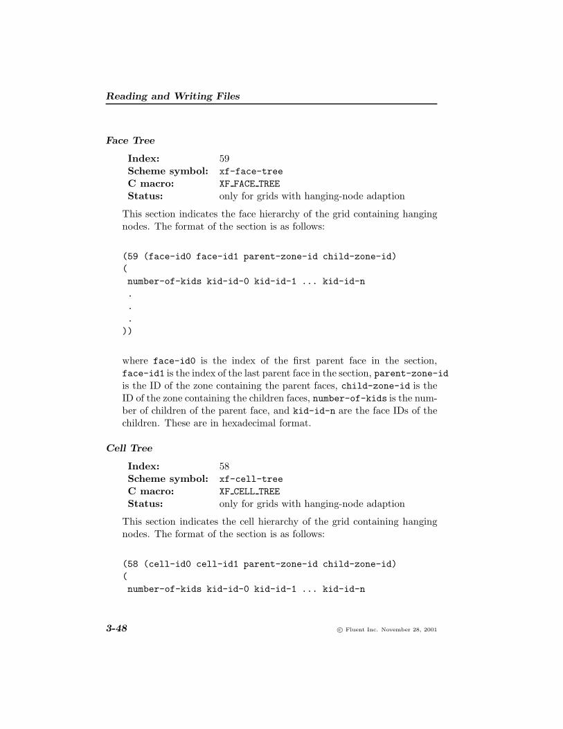
Index: 59Scheme symbol: xf-face-treeC macro: XF FACE TREEStatus: only for grids with hanging-node adaption
This section indicates the face hierarchy of the grid containing hangingnodes. The format of the section is as follows:
(59 (face-id0 face-id1 parent-zone-id child-zone-id)(number-of-kids kid-id-0 kid-id-1 ... kid-id-n...
))
where face-id0 is the index of the first parent face in the section,face-id1 is the index of the last parent face in the section, parent-zone-idis the ID of the zone containing the parent faces, child-zone-id is theID of the zone containing the children faces, number-of-kids is the num-ber of children of the parent face, and kid-id-n are the face IDs of thechildren. These are in hexadecimal format.
Cell Tree
Index: 58Scheme symbol: xf-cell-treeC macro: XF CELL TREEStatus: only for grids with hanging-node adaption
This section indicates the cell hierarchy of the grid containing hangingnodes. The format of the section is as follows:
(58 (cell-id0 cell-id1 parent-zone-id child-zone-id)(number-of-kids kid-id-0 kid-id-1 ... kid-id-n
3-48 c© Fluent Inc. November 28, 2001

3.18 Formats of Case and Data Files
.
.
.))
where cell-id0 is the index of the first parent cell in the section,cell-id1 is the index of the last parent cell in the section, parent-zone-idis the ID of the zone containing the parent cells, child-zone-id is theID of the zone containing the children cells, number-of-kids is the num-ber of children of the parent cell, and kid-id-n are the cell IDs of thechildren. These are in hexadecimal format.
Interface Face Parents
Index: 61Scheme symbol: xf-face-parentsC macro: XF FACE PARENTSStatus: only for grids with non-conformal interfaces
This section indicates the relationship between the intersection faces andoriginal faces. The intersection faces (children) are produced from inter-secting two non-conformal surfaces (parents) and are some fraction ofthe original face. Each child will refer to at least one parent.
The format of the section is as follows:
(61 (face-id0 face-id1)(parent-id-0 parent-id-1...
))
where face-id0 is the index of the first child face in the section, face-id1is the index of the last child face in the section, parent-id-0 is the in-dex of the right-side parent face, and parent-id-1 is the index of theleft-side parent face. These are in hexadecimal format.
c© Fluent Inc. November 28, 2001 3-49

Reading and Writing Files
If you read a non-conformal grid from FLUENT into TGrid, TGrid willskip this section, so it will not maintain all the information necessary topreserve the non-conformal interface. When you read the grid back intoFLUENT, you will need to recreate the interface.
Example Files
Example 1
Figure 3.18.1 illustrates a simple quadrilateral mesh with no periodicboundaries or hanging nodes.
bf8 bf7 bf6
bf3 bf4 bf5
bf10bf9 c1 c2 c3f1 f2
bn8 bn2 bn4 bn7
bn5 bn1 bn3 bn6
Figure 3.18.1: Quadrilateral Mesh
The following describes this mesh:
(0 "Grid:")
(0 "Dimensions:")(2 2)
(12 (0 1 3 0))(13 (0 1 a 0))(10 (0 1 8 0 2))
(12 (7 1 3 1 3))
3-50 c© Fluent Inc. November 28, 2001

3.18 Formats of Case and Data Files
(13 (2 1 2 2 2)(1 2 1 23 4 2 3))
(13 (3 3 5 3 2)(5 1 1 01 3 2 03 6 3 0))
(13 (4 6 8 3 2)(7 4 3 04 2 2 02 8 1 0))
(13 (5 9 9 a 2)(8 5 1 0))
(13 (6 a a 24 2)(6 7 3 0))
(10 (1 1 8 1 2)(1.00000000e+00 0.00000000e+001.00000000e+00 1.00000000e+002.00000000e+00 0.00000000e+002.00000000e+00 1.00000000e+000.00000000e+00 0.00000000e+003.00000000e+00 0.00000000e+003.00000000e+00 1.00000000e+000.00000000e+00 1.00000000e+00))
c© Fluent Inc. November 28, 2001 3-51

Reading and Writing Files
Example 2
Figure 3.18.2 illustrates a simple quadrilateral mesh with periodic bound-aries but no hanging nodes. In this example, bf9 and bf10 are faces onthe periodic zones.
bf8 bf7 bf6
bf3 bf4 bf5
bf10bf9 c1 c2 c3f1 f2
bn8 bn2 bn4 bn7
bn5 bn1 bn3 bn6
Figure 3.18.2: Quadrilateral Mesh with Periodic Boundaries
The following describes this mesh:
(0 "Dimensions:")(2 2)
(0 "Grid:")
(12 (0 1 3 0))(13 (0 1 a 0))(10 (0 1 8 0 2))
(12 (7 1 3 1 3))
(13 (2 1 2 2 2)(1 2 1 23 4 2 3))
(13 (3 3 5 3 2)(
3-52 c© Fluent Inc. November 28, 2001

3.18 Formats of Case and Data Files
5 1 1 01 3 2 03 6 3 0))
(13 (4 6 8 3 2)(7 4 3 04 2 2 02 8 1 0))
(13 (5 9 9 c 2)(8 5 1 0))
(13 (1 a a 8 2)(6 7 3 0))
(18 (1 1 5 1)(9 a))
(10 (1 1 8 1 2)(1.00000000e+00 0.00000000e+001.00000000e+00 1.00000000e+002.00000000e+00 0.00000000e+002.00000000e+00 1.00000000e+000.00000000e+00 0.00000000e+003.00000000e+00 0.00000000e+003.00000000e+00 1.00000000e+000.00000000e+00 1.00000000e+00))
c© Fluent Inc. November 28, 2001 3-53

Reading and Writing Files
Example 3
Figure 3.18.3 illustrates a simple quadrilateral mesh with hanging nodes.
bf15 bf14 bf12
bf8 bf9 bf11
bf17
bf16 c1 c2f5
f6
bn13 bn7 bn8 bn12
bn10 bn6 bn9 bn11
f7
c3
c4c5
c6
bf13bn2
f4 f2
bf18
bn3n5n1
bn4 bf10
f3
f1
Figure 3.18.3: Quadrilateral Mesh with Hanging Nodes
The following describes this mesh:
(0 "Grid:")
(0 "Dimensions:")(2 2)
(12 (0 1 7 0))(13 (0 1 16 0))(10 (0 1 d 0 2))
(12 (7 1 6 1 3))(12 (1 7 7 20 3))
(58 (7 7 1 7)(4 6 5 4 3))
(13 (2 1 7 2 2)(1 2 6 31 3 3 4
3-54 c© Fluent Inc. November 28, 2001

3.18 Formats of Case and Data Files
1 4 4 51 5 5 66 7 1 25 8 2 69 5 2 5))
(13 (3 8 b 3 2)(a 6 1 06 9 2 04 b 4 09 4 5 0))
(13 (4 c f 3 2)(2 8 6 0c 2 3 08 7 2 07 d 1 0))
(13 (5 10 10 a 2)(d a 1 0))
(13 (6 11 12 24 2)(3 c 3 0b 3 4 0))
(13 (b 13 13 1f 2)(c 8 7 0))
(13 (a 14 14 1f 2)(b c 7 0))
(13 (9 15 15 1f 2)(9 b 7 0))
(13 (8 16 16 1f 2)(9 8 2 7))
c© Fluent Inc. November 28, 2001 3-55

Reading and Writing Files
(59 (13 13 b 4)(2 d c))
(59 (14 14 a 6)(2 12 11))
(59 (15 15 9 3)(2 b a))
(59 (16 16 8 2)(2 7 6))
(10 (1 1 d 1 2)(2.50000000e+00 5.00000000e-012.50000000e+00 1.00000000e+003.00000000e+00 5.00000000e-012.50000000e+00 0.00000000e+002.00000000e+00 5.00000000e-011.00000000e+00 0.00000000e+001.00000000e+00 1.00000000e+002.00000000e+00 1.00000000e+002.00000000e+00 0.00000000e+000.00000000e+00 0.00000000e+003.00000000e+00 0.00000000e+003.00000000e+00 1.00000000e+000.00000000e+00 1.00000000e+00))
3-56 c© Fluent Inc. November 28, 2001

3.18 Formats of Case and Data Files
3.18.3 Other (Non-Grid) Case Sections
The following sections store boundary conditions, material properties,and solver control settings.
Zone
Index: 39 (45)Scheme symbol: xf-rp-tvC macro: XF RP TVStatus: required
There is typically one zone section for each zone referenced by the grid.Although some grid zones may not have corresponding zone sections,there cannot be more than one zone section for each zone.
A zone section has the following form:
(39 (zone-id zone-type zone-name)((condition1 . value1)(condition2 . value2)(condition3 . value3)...))
Grid generators and other preprocessors need only provide the sectionheader and leave the list of conditions empty, as in
(39 (zone-id zone-type zone-name)())
The empty parentheses at the end are required. The solver adds condi-tions as appropriate, depending on the zone type. When only zone-id,zone-type, and zone-name are specified, the index 45 is preferred for azone section. However, the index 39 must be used if boundary conditionsare present, because any and all remaining information in a section ofindex 45 after zone-id, zone-type, and zone-name will be ignored.
c© Fluent Inc. November 28, 2001 3-57

Reading and Writing Files
Here the zone-id is in decimal format. This is in contrast to the use ofhexadecimal in the grid sections.
The zone-type is one of the following:
axisexhaust fanfanfluidinlet ventintake faninterfaceinteriormass-flow-inletoutlet ventoutflowperiodicporous-jumppressure-far-fieldpressure-inletpressure-outletradiatorshadowsolidsymmetryvelocity-inletwall
The interior, fan, porous-jump, and radiator types can be assignedonly to zones of faces inside the domain. The interior type is used forthe faces within a cell zone; the others are for interior faces that forminfinitely thin surfaces within the domain. FLUENT allows the wall typeto be assigned to face zones both on the inside and on the boundariesof the domain. Some zone types are valid only for certain types of gridcomponents. For example, cell (element) zones can be assigned only oneof the following types:
3-58 c© Fluent Inc. November 28, 2001

3.18 Formats of Case and Data Files
fluidsolid
All of the other types listed above can be used only for boundary (face)zones.
The zone-name is a user-specified label for the zone. It must be a validScheme symbol1 and is written without quotes. The rules for a validzone-name (Scheme symbol) are as follows:
• The first character must be a lowercase letter2 or a special-initial.
• Each subsequent character must be a lowercase letter, a special-initial, a digit, or a special-subsequent.
where a special-initial character is one of the following:
! $ % & * / : < = > ? ~ _ ^
and a special-subsequent is one of the following:
. + -
Examples of valid zone names are inlet-port/cold!, eggs/easy, ande=m*c^2.
Below are some examples of zone sections produced by grid generatorsand preprocessors.
(39 (1 fluid fuel)())
(39 (8 pressure-inlet pressure-inlet-8)())
(39 (2 wall wing-skin)())
(39 (3 symmetry mid-plane)())
1See Revised(4) Report on the Algorithmic Language Scheme, William Clinger andJonathan Rees (Editors), 2 November 1991, Section 7.1.1.
2The Standard actually only requires that case be insignificant; the Fluent Inc.implementation accomplishes this by converting all uppercase input to lowercase.
c© Fluent Inc. November 28, 2001 3-59

Reading and Writing Files
Partitions
Index: 40Scheme symbol: xf-partitionC macro: XF PARTITIONStatus: only for partitioned grids
This section indicates each cell’s partition. The format of the section isas follows:
(40 (zone-id first-index last-index partition-count)(p1p2p3...pn))
p1 is the partition of the cell whose ID is first-index, p2 is the partitionof the cell whose ID is first-index+1, etc., and pn is the partition ofthe cell whose ID is last-index. Partition IDs must be between 0 andpartition-count−1, where partition-count is the total number ofpartitions.
3.18.4 Data Sections
The following sections store iterations, residuals, and data field values.
Grid Size
Index: 33Scheme symbol: xf-grid-sizeC macro: XF GRID SIZEStatus: optional
This section indicates the number of cells, faces, and nodes in the gridthat corresponds to the data in the file. This information is used to checkthat the data and grid match. The format is
3-60 c© Fluent Inc. November 28, 2001

3.18 Formats of Case and Data Files
(33 (n-elements n-faces n-nodes))
where the integers are written in decimal.
Data Field
Index: 300Scheme symbol: xf-rf-seg-dataC macro: XF RF SEG DATAStatus: required
This section lists a flow field solution variable for a cell or face zone. Thedata are stored in the same order as the cells or faces in the case file.Separate sections are written out for each variable for each face or cellzone on which the variable is stored. The format is
(300 (sub-section-id zone-id size n-time-levelsn-phases first-id last-id)
( data for cell or face with id = first-iddata-for-cell-or-face with id = first-id+1..data-for-cell-or-face with id = last-id
))
where sub-section-id is a (decimal) integer that identifies the variablefield (e.g., 1 for pressure, 2 for velocity). The complete list of these isavailable in the header file (xfile.h), which is located in the followingdirectory in your installation area:
/Fluent.Inc/fluent6.x/client/src/xfile.h
zone-id is the ID number of the cell or face zone and matches the IDused in case file. size denotes the length of the variable vector (1 for ascalar, 2 or 3 for a vector, equal to the number of species for variablesdefined for each species). n-time-levels and n-phases currently arenot used.
A sample data file section for the velocity field in a cell zone for a steady-state, single-phase, 2D problem is shown below:
c© Fluent Inc. November 28, 2001 3-61

Reading and Writing Files
(300 (2 16 2 0 0 17 100)(8.08462024e-01 8.11823010e-028.78750622e-01 3.15509699e-021.06139672e+00 -3.74040119e-02...1.33301604e+00 -5.04243895e-026.21703446e-01 -2.46118382e-024.41687912e-01 -1.27046436e-011.03528820e-01 -1.01711005e-01
))
The variables that are listed in the data file depend on the models activeat the time the file is written. Variables that are required by the solverbased on the current model settings but are missing from the data file areset to their default values when the data file is read. Any extra variablesthat are present in the data file but are not relevant according to currentmodel settings are ignored.
Residuals
Index: 301Scheme symbol: xf-rf-seg-residualsC macro: XF RF SEG RESIDUALSStatus: optional
This section lists the values of the residuals for a particular data fieldvariable at each iteration:
(301 (n residual-subsection-id size)(r1r2...rn))
where n is the number of residuals and size is the length of the variablevector (1 for a scalar, 2 or 3 for a vector, equal to the number of species
3-62 c© Fluent Inc. November 28, 2001

3.18 Formats of Case and Data Files
for variables defined for each species). The residual-subsection-idis an integer (decimal) indicating the equation for which the residual isstored in the section, according to the C constants defined in a header file(xfile.h) available in your installation area, as noted in Section 3.18.2.
The equations for which residuals are listed in the data file depend onthe models active at the time the file is written. If the residual history ismissing from the data file for a currently active equation, it is initializedwith zeros.
c© Fluent Inc. November 28, 2001 3-63

Reading and Writing Files
3-64 c© Fluent Inc. November 28, 2001