Embed Size (px)
Citation preview
1
Chapter 3Resistive Network Analysis
Jaesung Jang
Node Voltage/Mesh Current MethodSuperposition
Thevenin and Norton Equivalent CircuitsVoltage and Current Source Transformation
Maximum Power Transfer
2
Network Analysis• The analysis of electrical network consists of determining each
of unknown branch currents (currents flowing through each branch) and node voltages (voltage at each node).
• Once the known (usually resistances and sources) and unknown (branch currents and node voltages) variables are identified, a set of equations relating these variables is constructed.
• If the number of unknown variables and equations are equal, the set of equations can be solved.
3
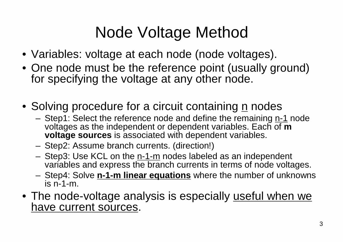
Node Voltage Method• Variables: voltage at each node (node voltages).• One node must be the reference point (usually ground)
for specifying the voltage at any other node.
• Solving procedure for a circuit containing n nodes– Step1: Select the reference node and define the remaining n-1 node
voltages as the independent or dependent variables. Each of m voltage sources is associated with dependent variables.
– Step2: Assume branch currents. (direction!)– Step3: Use KCL on the n-1-m nodes labeled as an independent
variables and express the branch currents in terms of node voltages.– Step4: Solve n-1-m linear equations where the number of unknowns
is n-1-m.
• The node-voltage analysis is especially useful when we have current sources.
4
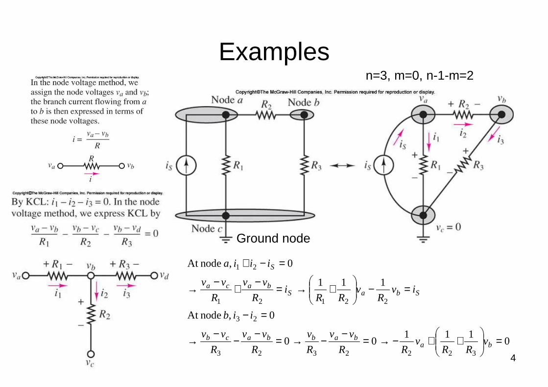
Examples
0111
00
0 , nodeAt
111
0 , nodeAt
3222323
23
22121
21
=
++−→=
−−→=
−−
−→
=−
=−
+→=
−+
−→
=−+
bababbacb
SbaSbaca
S
vRR
vRR
vv
R
v
R
vv
R
vv
iib
ivR
vRR
iR
vv
R
vv
iiia
n=3, m=0, n-1-m=2
Ground node
5
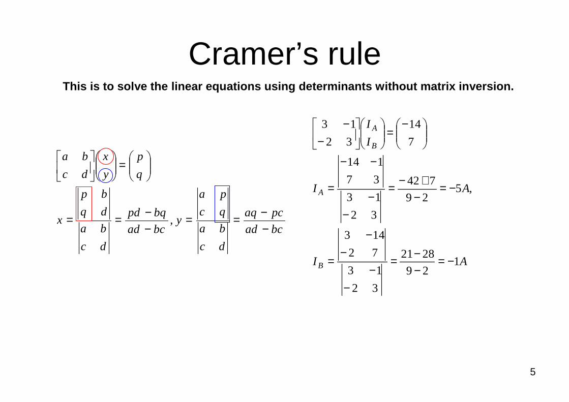
Cramer’s rule
bcad
pcaq
dc
ba
qc
pa
ybcad
bqpd
dc
ba
dq
bp
x
q
p
y
x
dc
ba
−−==
−−==
=
,
AI
AI
I
I
B
A
B
A
129
2821
32
13
72
143
,529
742
32
13
37
114
7
14
32
13
−=−−=
−−
−−
=
−=−
+−=
−−
−−
=
−=
−−
This is to solve the linear equations using determi nants without matrix inversion.
6
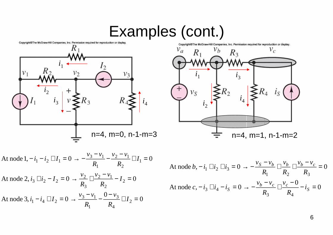
Examples (cont.)
00
0 ,3 nodeAt
00 ,2 nodeAt
00 ,1 nodeAt
24
3
1
13241
22
12
3
2223
12
12
1
13121
=+−
−−
→=+−
=−−+→=−+
=+−
−−
−→=+−−
IR
v
R
vvIii
IR
vv
R
vIii
IR
vv
R
vvIii
00
0 , nodeAt
00 , nodeAt
4343
321321
=−−
+−
−→=−+−
=−++−−→=++−
Sccb
S
cbbbS
iR
v
R
vviiic
R
vv
R
v
R
vviiib
n=4, m=1, n-1-m=2n=4, m=0, n-1-m=3
i2
i3
i1
i4 i2
i3i1
i4
7
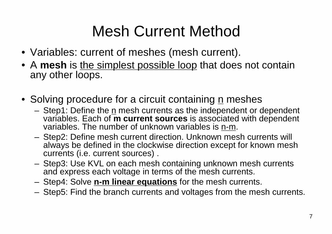
Mesh Current Method• Variables: current of meshes (mesh current).• A mesh is the simplest possible loop that does not contain
any other loops.
• Solving procedure for a circuit containing n meshes– Step1: Define the n mesh currents as the independent or dependent
variables. Each of m current sources is associated with dependent variables. The number of unknown variables is n-m.
– Step2: Define mesh current direction. Unknown mesh currents will always be defined in the clockwise direction except for known mesh currents (i.e. current sources) .
– Step3: Use KVL on each mesh containing unknown mesh currents and express each voltage in terms of the mesh currents.
– Step4: Solve n-m linear equations for the mesh currents.– Step5: Find the branch currents and voltages from the mesh currents.
8
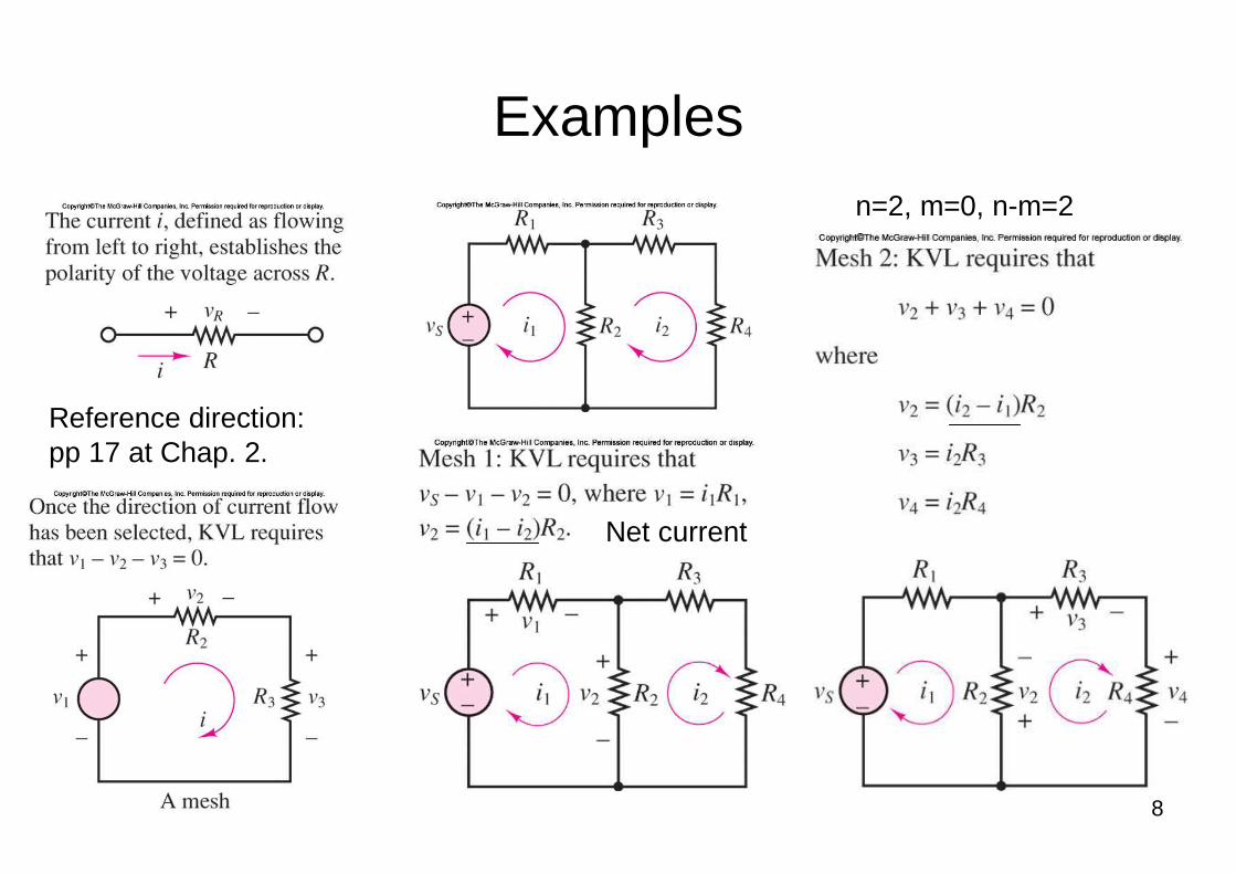
Examplesn=2, m=0, n-m=2
Reference direction: pp 17 at Chap. 2.
Net current
9
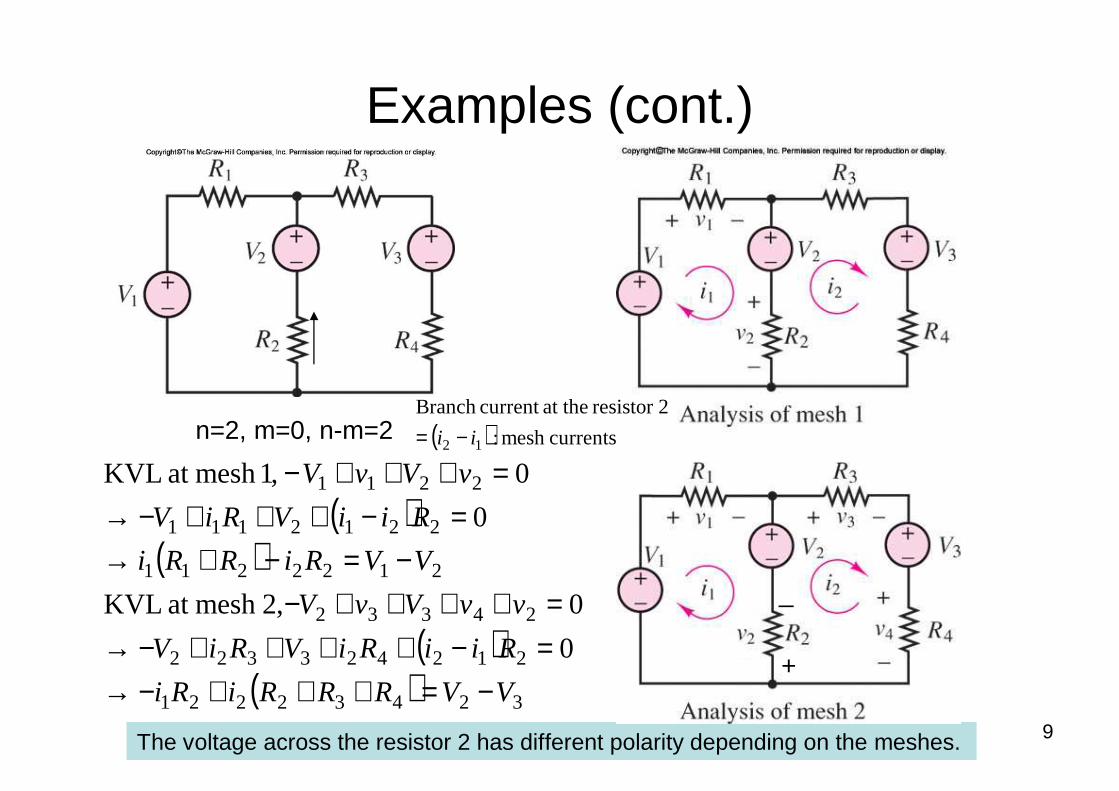
Examples (cont.)
( )( )
( )( ) 32432221
212423322
24332
2122211
2212111
2211
0
0,2mesh at KVL
0
0 ,1mesh at KVL
VVRRRiRi
RiiRiVRiV
vvVvV
VVRiRRi
RiiVRiV
vVvV
−=+++−→=−++++−→=++++−
−=−+→=−+++−→
=+++−n=2, m=0, n-m=2
The voltage across the resistor 2 has different polarity depending on the meshes.
+
_
( ) currentsmesh :
2resistor at thecurrent Branch
12 ii −=
10
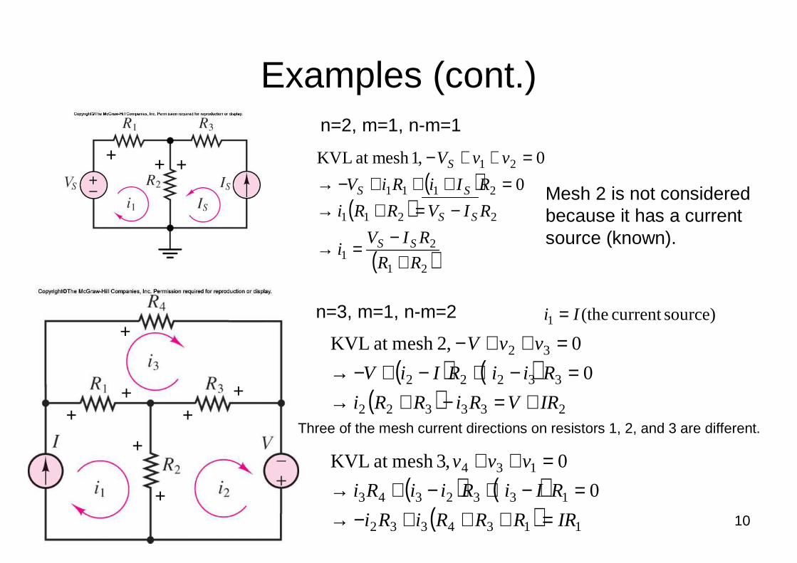
Examples (cont.)
( )( )
( )21
21
2211
2111
21
0
0 ,1mesh at KVL
RR
RIVi
RIVRRi
RIiRiV
vvV
SS
SS
SS
S
+−
=→
−=+→=+++−→
=++−
n=2, m=1, n-m=1
( ) ( )( )
( ) ( )( ) 1134332
1332343
134
233322
33222
32
0
0,3mesh at KVL
0
0 ,2mesh at KVL
IRRRRiRi
RIiRiiRi
vvv
IRVRiRRi
RiiRIiV
vvV
=+++−→=−+−+→
=++
+=−+→=−+−+−→
=++−
n=3, m=1, n-m=2
Mesh 2 is not considered because it has a current source (known).
+ + +
source)current (the1 Ii =+
+
+
++
+
+Three of the mesh current directions on resistors 1, 2, and 3 are different.
11
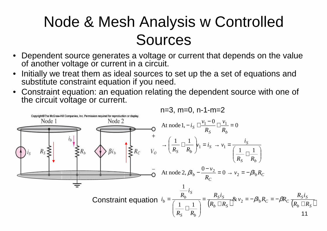
Node & Mesh Analysis w Controlled Sources
• Dependent source generates a voltage or current that depends on the value of another voltage or current in a circuit.
• Initially we treat them as ideal sources to set up the a set of equations and substitute constraint equation if you need.
• Constraint equation: an equation relating the dependent source with one of the circuit voltage or current.
( ) ( )Sb
SSCCb
Sb
SS
bS
Sb
b
CbC
b
bS
SS
bS
bSS
RR
iRRRiv
RR
iR
RR
iR
i
RivR
vi
RR
iviv
RR
R
v
R
vi
+−=−=
+=
+
=
−=→=−−
+
=→=
+→
=+−+−
ββ
ββ
2
22
11
11
&11
1
00
,2 nodeAt
11
11
00
,1 nodeAt
n=3, m=0, n-1-m=2
Constraint equation
12
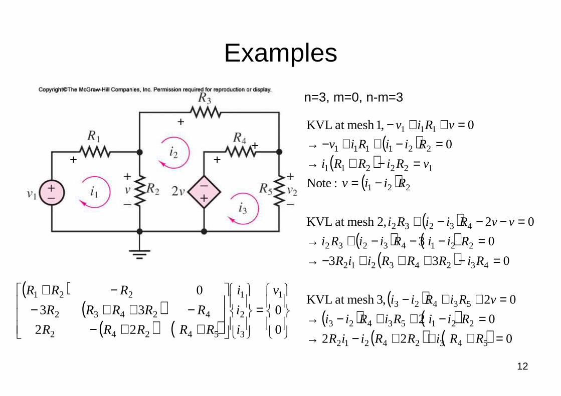
Examples
( )( )
( )
( )( ) ( )
( )
( )( ) ( )
( ) ( ) 022
02
02,3mesh at KVL
033
03
02,2mesh at KVL
:Note
0
0 ,1mesh at KVL
54324212
22153423
53423
43243212
22143232
43232
221
122211
221111
111
=+++−→=−++−→
=++−
=−+++−→=−−−+→
=−−−+
−==−+→
=−++−→=++−
RRiRRiiR
RiiRiRii
vRiRii
RiRRRiiR
RiiRiiRi
vvRiiRi
Riiv
vRiRRi
RiiRiv
vRiv
n=3, m=0, n-m=3
++
+
+
( )( )
( ) ( )
=
++−−++−
−+
0
0
22
33
0 1
3
2
1
54242
42432
221 v
i
i
i
RRRRR
RRRRR
RRR
13
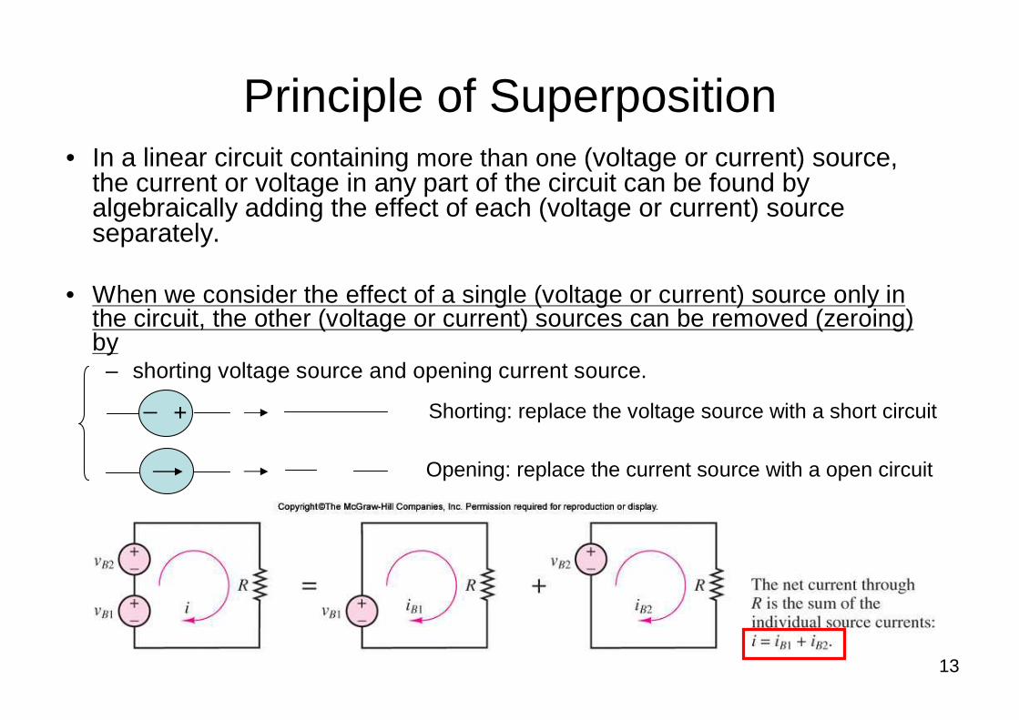
Principle of Superposition• In a linear circuit containing more than one (voltage or current) source,
the current or voltage in any part of the circuit can be found by algebraically adding the effect of each (voltage or current) source separately.
• When we consider the effect of a single (voltage or current) source only in the circuit, the other (voltage or current) sources can be removed (zeroing) by
– shorting voltage source and opening current source.
+_ Shorting: replace the voltage source with a short circuit
Opening: replace the current source with a open circuit
14
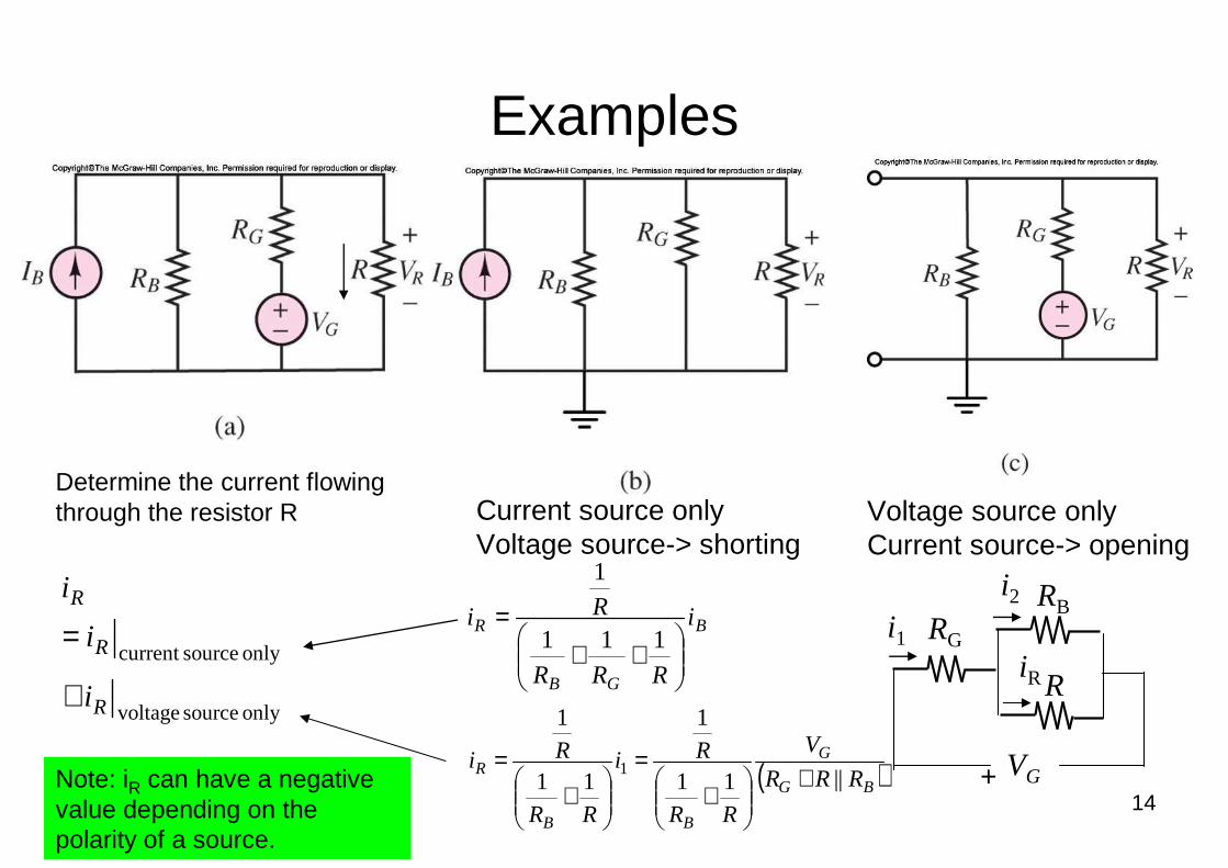
Examples
only source voltage
only sourcecurrent
R
R
R
i
i
i
+
=
Determine the current flowing through the resistor R Current source only
Voltage source-> shortingVoltage source only Current source-> opening
B
GB
R i
RRR
Ri
++
=111
1
( )BG
G
BB
R RRR
V
RR
Ri
RR
Ri||11
1
11
1
1 +
+
=
+
=Note: iR can have a negative value depending on the polarity of a source.
i1 RG
RBi2
VG
RiR
+
15
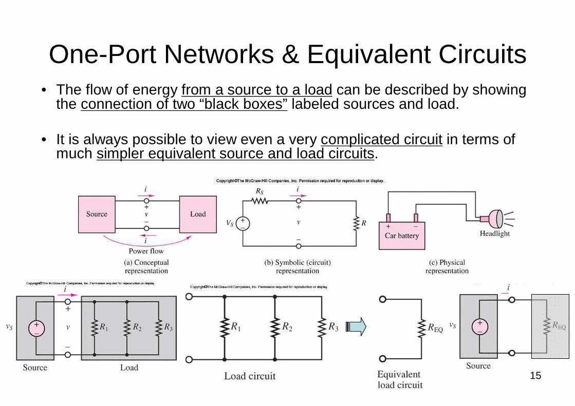
One-Port Networks & Equivalent Circuits• The flow of energy from a source to a load can be described by showing
the connection of two “black boxes” labeled sources and load.
• It is always possible to view even a very complicated circuit in terms of much simpler equivalent source and load circuits.
16
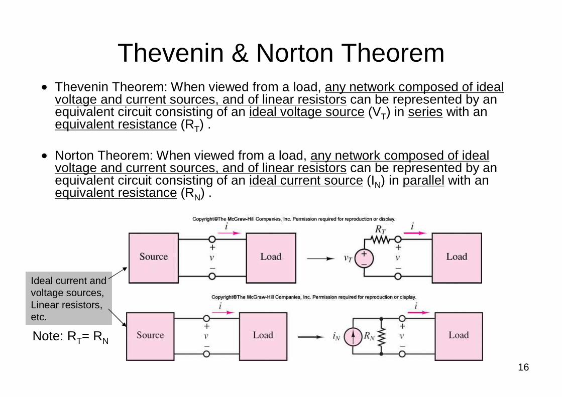
Thevenin & Norton Theorem• Thevenin Theorem: When viewed from a load, any network composed of ideal
voltage and current sources, and of linear resistors can be represented by an equivalent circuit consisting of an ideal voltage source (VT) in series with an equivalent resistance (RT) .
• Norton Theorem: When viewed from a load, any network composed of ideal voltage and current sources, and of linear resistors can be represented by an equivalent circuit consisting of an ideal current source (IN) in parallel with an equivalent resistance (RN) .
Ideal current and voltage sources, Linear resistors, etc.
Note: RT= RN
17
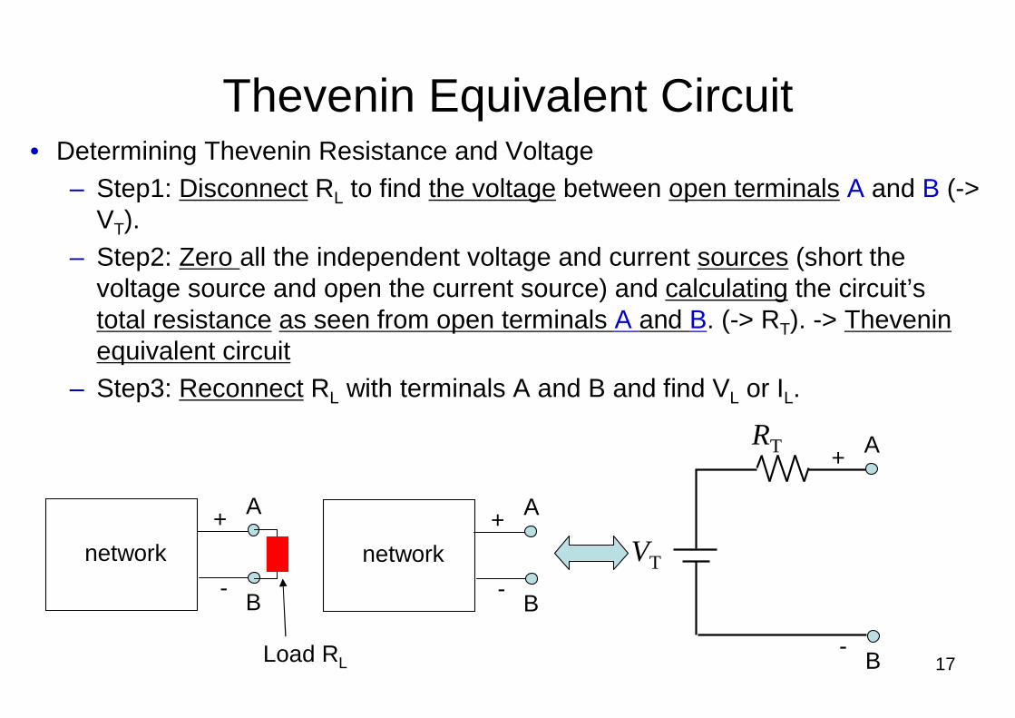
Thevenin Equivalent Circuit• Determining Thevenin Resistance and Voltage
– Step1: Disconnect RL to find the voltage between open terminals A and B (->VT).
– Step2: Zero all the independent voltage and current sources (short the voltage source and open the current source) and calculating the circuit’s total resistance as seen from open terminals A and B. (-> RT). -> Thevenin equivalent circuit
– Step3: Reconnect RL with terminals A and B and find VL or IL.
network
A
B
+
-
RT
VT
A
B
+
-
network
A
B
+
-
Load RL
18
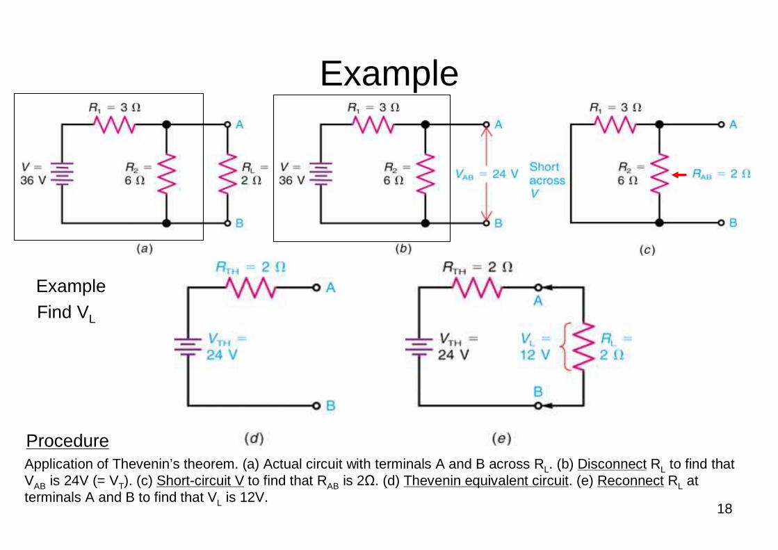
Example
Application of Thevenin’s theorem. (a) Actual circuit with terminals A and B across RL. (b) Disconnect RL to find that VAB is 24V (= VT). (c) Short-circuit V to find that RAB is 2Ω. (d) Thevenin equivalent circuit. (e) Reconnect RL at terminals A and B to find that VL is 12V.
Example
Procedure
Find VL
19
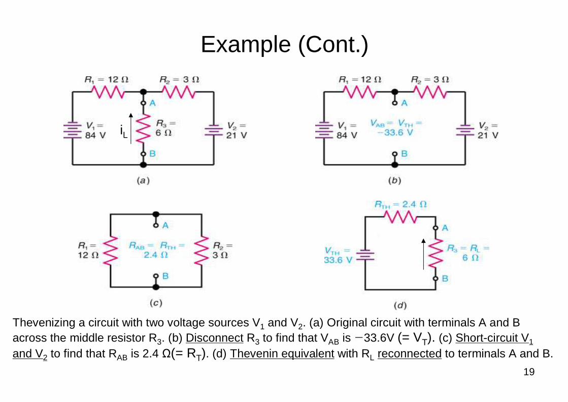
Example (Cont.)
Thevenizing a circuit with two voltage sources V1 and V2. (a) Original circuit with terminals A and B across the middle resistor R3. (b) Disconnect R3 to find that VAB is −33.6V (= VT). (c) Short-circuit V1
and V2 to find that RAB is 2.4 Ω(= RT). (d) Thevenin equivalent with RL reconnected to terminals A and B.
iL
20
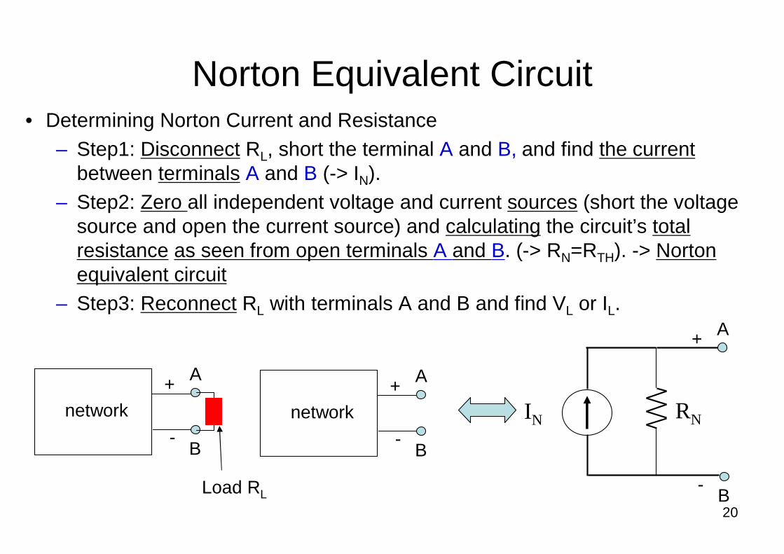
Norton Equivalent Circuit• Determining Norton Current and Resistance
– Step1: Disconnect RL, short the terminal A and B, and find the currentbetween terminals A and B (-> IN).
– Step2: Zero all independent voltage and current sources (short the voltage source and open the current source) and calculating the circuit’s total resistance as seen from open terminals A and B. (-> RN=RTH). -> Norton equivalent circuit
– Step3: Reconnect RL with terminals A and B and find VL or IL.
network
A
B
+
-
RNIN
A
B
+
-
network
A
B
+
-
Load RL
21
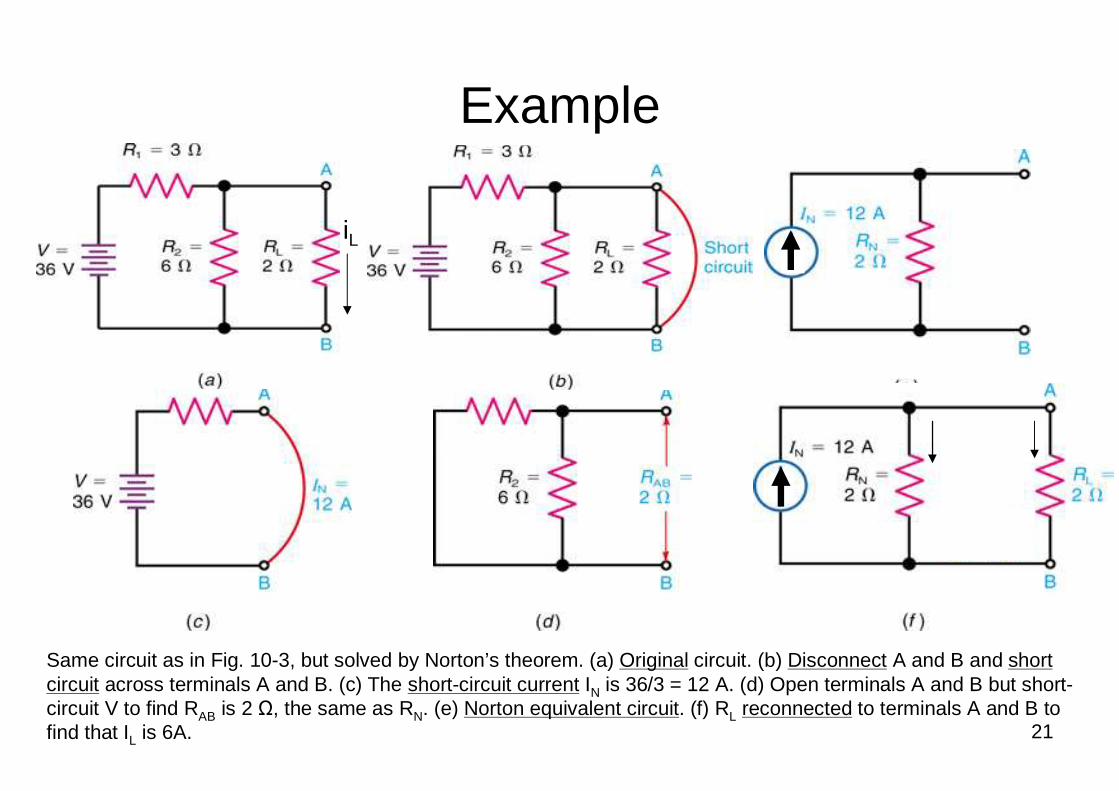
Example
Same circuit as in Fig. 10-3, but solved by Norton’s theorem. (a) Original circuit. (b) Disconnect A and B and short circuit across terminals A and B. (c) The short-circuit current IN is 36/3 = 12 A. (d) Open terminals A and B but short-circuit V to find RAB is 2 Ω, the same as RN. (e) Norton equivalent circuit. (f) RL reconnected to terminals A and B to find that IL is 6A.
iL
22
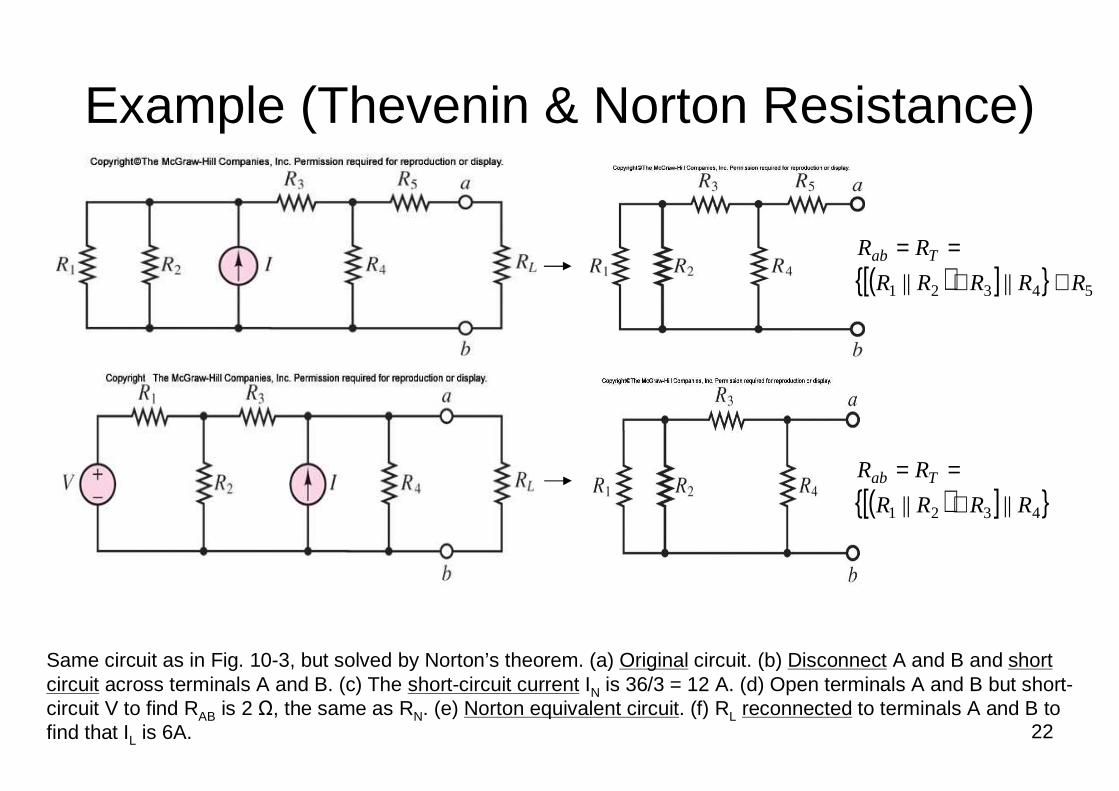
Example (Thevenin & Norton Resistance)
Same circuit as in Fig. 10-3, but solved by Norton’s theorem. (a) Original circuit. (b) Disconnect A and B and short circuit across terminals A and B. (c) The short-circuit current IN is 36/3 = 12 A. (d) Open terminals A and B but short-circuit V to find RAB is 2 Ω, the same as RN. (e) Norton equivalent circuit. (f) RL reconnected to terminals A and B to find that IL is 6A.
( )[ ] 54321 |||| RRRRR
RR Tab
++==
( )[ ] 4321 |||| RRRR
RR Tab
+==
23
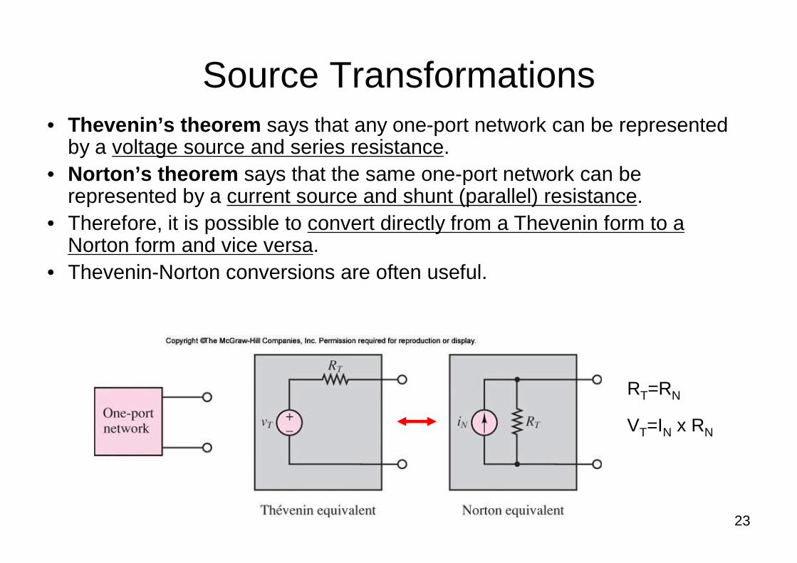
Source Transformations• Thevenin’s theorem says that any one-port network can be represented
by a voltage source and series resistance.• Norton’s theorem says that the same one-port network can be
represented by a current source and shunt (parallel) resistance.• Therefore, it is possible to convert directly from a Thevenin form to a
Norton form and vice versa.• Thevenin-Norton conversions are often useful.
RT=RN
VT=IN x RN
24
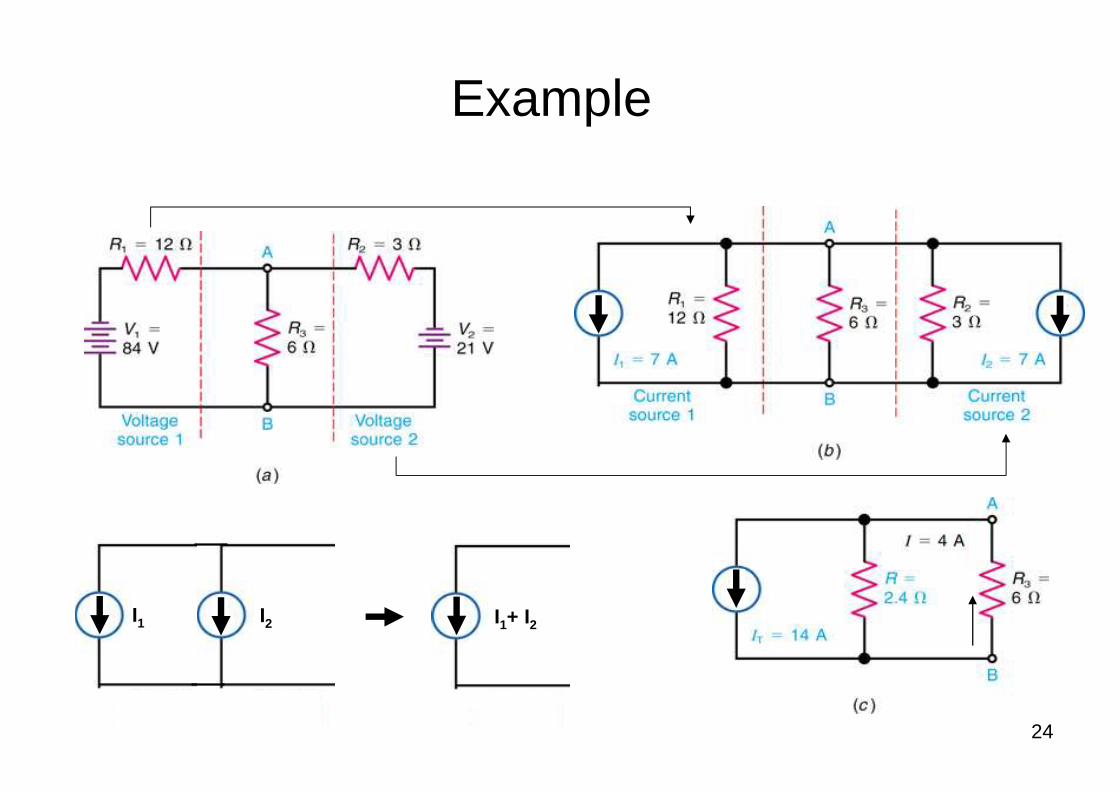
Example
I1 I2 I1+ I2
25
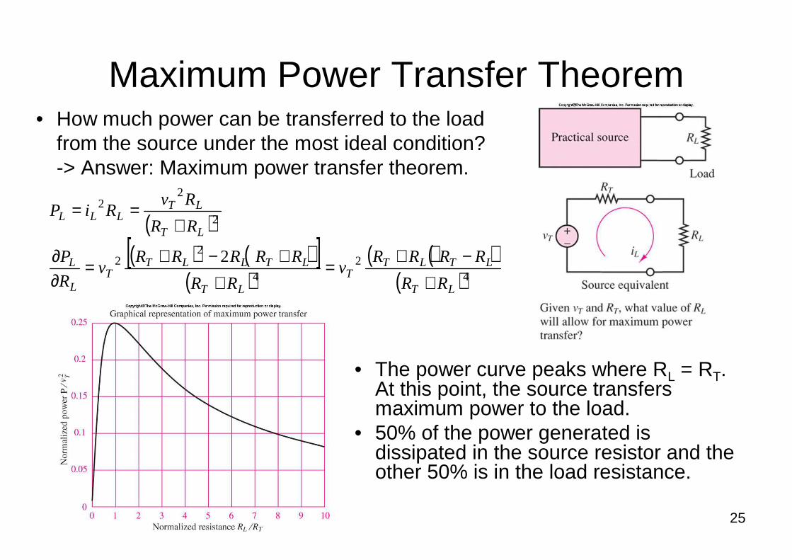
Maximum Power Transfer Theorem• How much power can be transferred to the load
from the source under the most ideal condition? -> Answer: Maximum power transfer theorem.
( )( ) ( )[ ]
( )( )( )
( )42
4
22
2
22
2
LT
LTLTT
LT
LTLLTT
L
L
LT
LTLLL
RR
RRRRv
RR
RRRRRv
R
P
RR
RvRiP
+−+=
++−+=
∂∂
+==
• The power curve peaks where RL = RT. At this point, the source transfers maximum power to the load.
• 50% of the power generated is dissipated in the source resistor and the other 50% is in the load resistance.