Embed Size (px)
Citation preview
CHAPTER 39
COOLING TOWERS
MOST air-conditioning systems and industrial processes generate heat that must be removed and dissipated. Water is commonly used as a heat transfer medium to remove heat from refrigerant condensers or industrial process heat exchangers. In the past, this was accomplished by drawing a continuous stream of water from a utility water supply or a natural body of water, heating it as it passed through the process, and then discharging the water directly to a sewer or returning it to the body of water. Water purchased from utilities for this purpose has now become prohibitively expensive because of increased water supply and disposal costs. Similarly, cooling water drawn from natural sources is relatively unavailable because the ecological disturbance caused by the increased temperature of discharge water has become unacceptable.
Air-cooled heat exchangers cool water by rejecting heat directly to the atmosphere, but the first cost and fan energy consumption of these devices are high and the plan area required is relatively large. They can economically cool water to within approximately 20°F of the ambient dry-bulb temperature—too high for the cooling water
requirements of most refrigeration systems and many industrial processes.
Cooling towers overcome most of these problems and therefore are commonly used to dissipate heat from water-cooled refrigeration, air-conditioning, and industrial process systems. The water consumption rate of a cooling tower system is only about 5% of that of a once-through system, making it the least expensive system to operate with purchased water supplies. Additionally, the amount of heated water discharged (blowdown) is very small, so the ecological effect is greatly reduced. Lastly, cooling towers can cool water to within 4 to 5°F of the ambient wet-bulb temperature, or about 35°F lower than can air-cooled systems of reasonable size. This lower temperature improves the efficiency of the overall system, thereby reducing energy use significantly and increasing process output.
PRINCIPLE OF OPERATION
A cooling tower cools water by a combination of heat and mass transfer. Water to be cooled is distributed in the tower by spray nozzles, splash bars, or film-type fill, which exposes a very large water surface area to atmospheric air. Atmospheric air is circulated by (1) fans, (2) convective currents, (3) natural wind currents, or (4) induction effect from sprays. A portion of the water absorbs heat to change from a liquid to a vapor at constant pressure. This heat of vaporization at atmospheric pressure is transferred from the water remaining in the liquid state into the airstream.
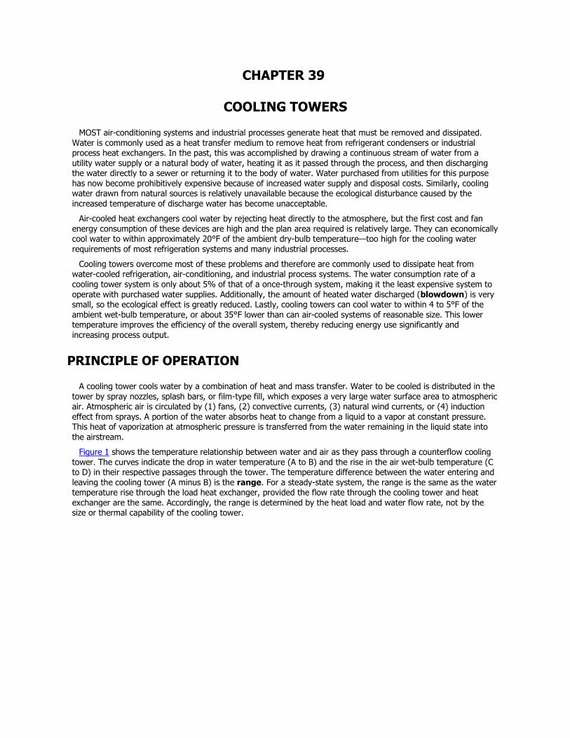
Figure 1 shows the temperature relationship between water and air as they pass through a counterflow cooling tower. The curves indicate the drop in water temperature (A to B) and the rise in the air wet-bulb temperature (C to D) in their respective passages through the tower. The temperature difference between the water entering and leaving the cooling tower (A minus B) is the range. For a steady-state system, the range is the same as the water temperature rise through the load heat exchanger, provided the flow rate through the cooling tower and heat exchanger are the same. Accordingly, the range is determined by the heat load and water flow rate, not by the size or thermal capability of the cooling tower.
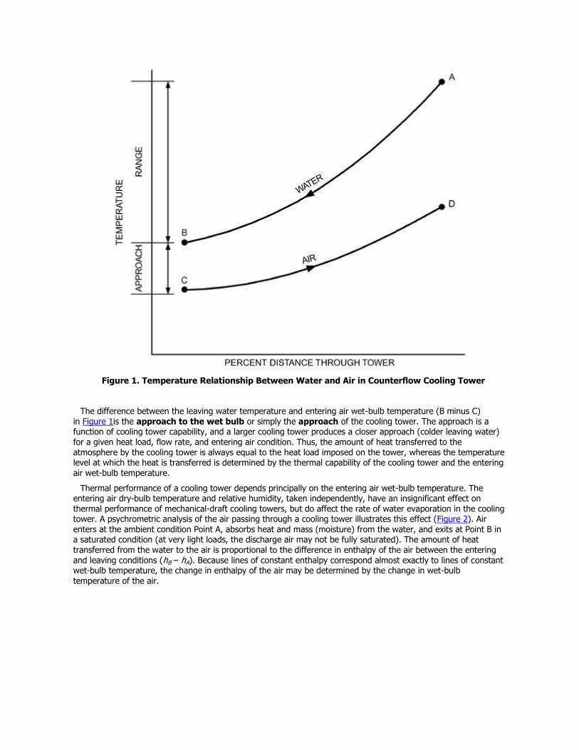
Figure 1. Temperature Relationship Between Water and Air in Counterflow Cooling Tower
The difference between the leaving water temperature and entering air wet-bulb temperature (B minus C) in Figure 1is the approach to the wet bulb or simply the approach of the cooling tower. The approach is a function of cooling tower capability, and a larger cooling tower produces a closer approach (colder leaving water) for a given heat load, flow rate, and entering air condition. Thus, the amount of heat transferred to the atmosphere by the cooling tower is always equal to the heat load imposed on the tower, whereas the temperature level at which the heat is transferred is determined by the thermal capability of the cooling tower and the entering air wet-bulb temperature.
Thermal performance of a cooling tower depends principally on the entering air wet-bulb temperature. The entering air dry-bulb temperature and relative humidity, taken independently, have an insignificant effect on thermal performance of mechanical-draft cooling towers, but do affect the rate of water evaporation in the cooling tower. A psychrometric analysis of the air passing through a cooling tower illustrates this effect (Figure 2). Air enters at the ambient condition Point A, absorbs heat and mass (moisture) from the water, and exits at Point B in a saturated condition (at very light loads, the discharge air may not be fully saturated). The amount of heat transferred from the water to the air is proportional to the difference in enthalpy of the air between the entering and leaving conditions (hB – hA). Because lines of constant enthalpy correspond almost exactly to lines of constant wet-bulb temperature, the change in enthalpy of the air may be determined by the change in wet-bulb
temperature of the air.
Figure 2. Psychrometric Analysis of Air Passing Through Cooling Tower
Air heating (Vector AB in Figure 2) may be separated into component AC, which represents the sensible portion of the heat absorbed by the air as the water is cooled, and component CB, which represents the latent portion. If the entering air condition is changed to Point D at the same wet-bulb temperature but at a higher dry-bulb temperature, the total heat transfer (Vector DB) remains the same, but the sensible and latent components change dramatically. DE represents sensible cooling of air, while EB represents latent heating as water gives up heat and mass to the air. Thus, for the same water-cooling load, the ratio of latent to sensible heat transfer can vary significantly.
The ratio of latent to sensible heat is important in analyzing water usage of a cooling tower. Mass transfer (evaporation) occurs only in the latent portion of heat transfer and is proportional to the change in specific humidity. Because the entering air dry-bulb temperature or relative humidity affects the latent to sensible heat transfer ratio, it also affects the rate of evaporation. In Figure 2, the rate of evaporation in Case AB (WB – WA) is less than in Case DB (WB – WD) because the latent heat transfer (mass transfer) represents a smaller portion of the total.
The evaporation rate at typical design conditions is approximately 1% of the water flow rate for each 12.5°F of water temperature range; however, the average evaporation rate over the operating season is less than the design rate because the sensible component of total heat transfer increases as entering air temperature decreases.
In addition to water loss from evaporation, losses also occur because of liquid carryover into the discharge airstream and blowdown to maintain acceptable water quality. Both of these factors are addressed later in this chapter.
DESIGN CONDITIONS
The thermal capability of any cooling tower may be defined by the following parameters:
Entering and leaving water temperatures
Entering air wet-bulb or entering air wet-bulb and dry-bulb temperatures
Water flow rate
The entering air dry-bulb temperature affects the amount of water evaporated from any evaporative cooling tower. It also affects airflow through hyperbolic towers and directly establishes thermal capability in any indirect-contact cooling tower component operating in a dry mode. Variations in tower performance associated with changes in the remaining parameters are covered in the section on Performance Curves.
The thermal capability of a cooling tower used for air conditioning is often expressed in nominal cooling tower tons. A nominal cooling tower ton is defined as cooling 3 gpm of water from 95°F to 85°F at a 78°F entering air wet-bulb temperature. At these conditions, the cooling tower rejects 15,000 Btu/h per nominal cooling tower ton. The historical derivation of this 15,000 Btu/h cooling tower ton, as compared to the 12,000 Btu/h evaporator ton, is based on the assumption that at typical air-conditioning conditions, for every 12,000 Btu/h of heat picked up in the evaporator, the cooling tower must dissipate an additional 3000 Btu/h of compressor heat. For specific applications, however, nominal tonnage ratings are not used, and the thermal performance capability of the tower is usually expressed as a water flow rate at specific operating temperature conditions (entering water temperature, leaving water temperature, entering air wet-bulb temperature).
TYPES OF COOLING TOWERS
Two basic types of evaporative cooling devices are used. The first of these, the direct-contact or open cooling tower (Figure 3), exposes water directly to the cooling atmosphere, thereby transferring the source heat load directly to the air. The second type, often called a closed-circuit cooling tower, involves indirect contact between heated fluid and atmosphere (Figure 4), essentially combining a heat exchanger and cooling tower into one relatively compact device.
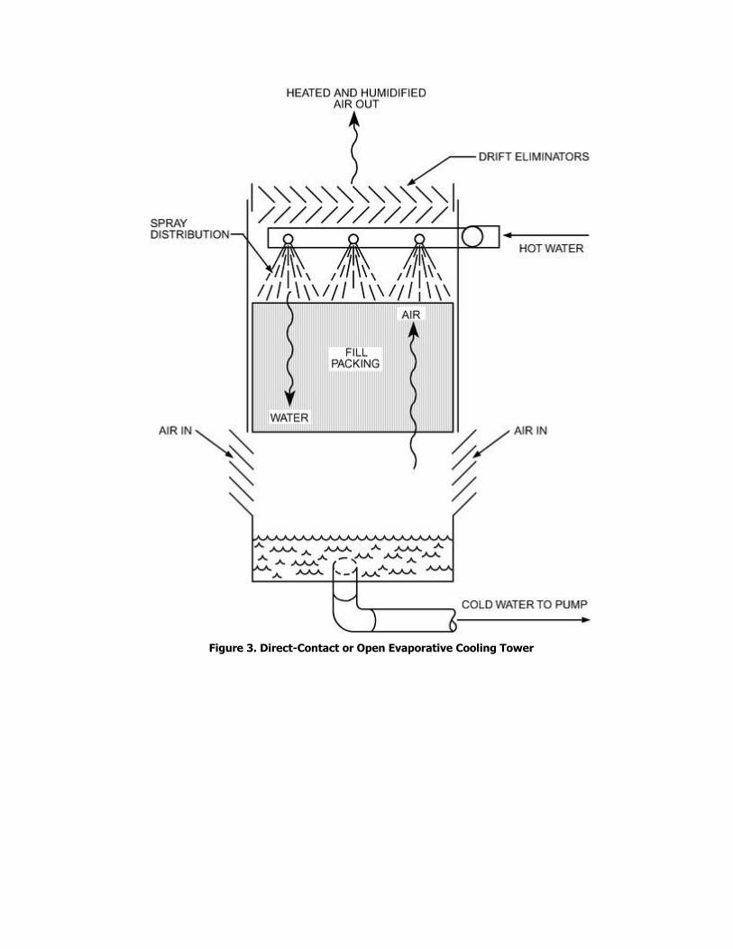
Figure 3. Direct-Contact or Open Evaporative Cooling Tower
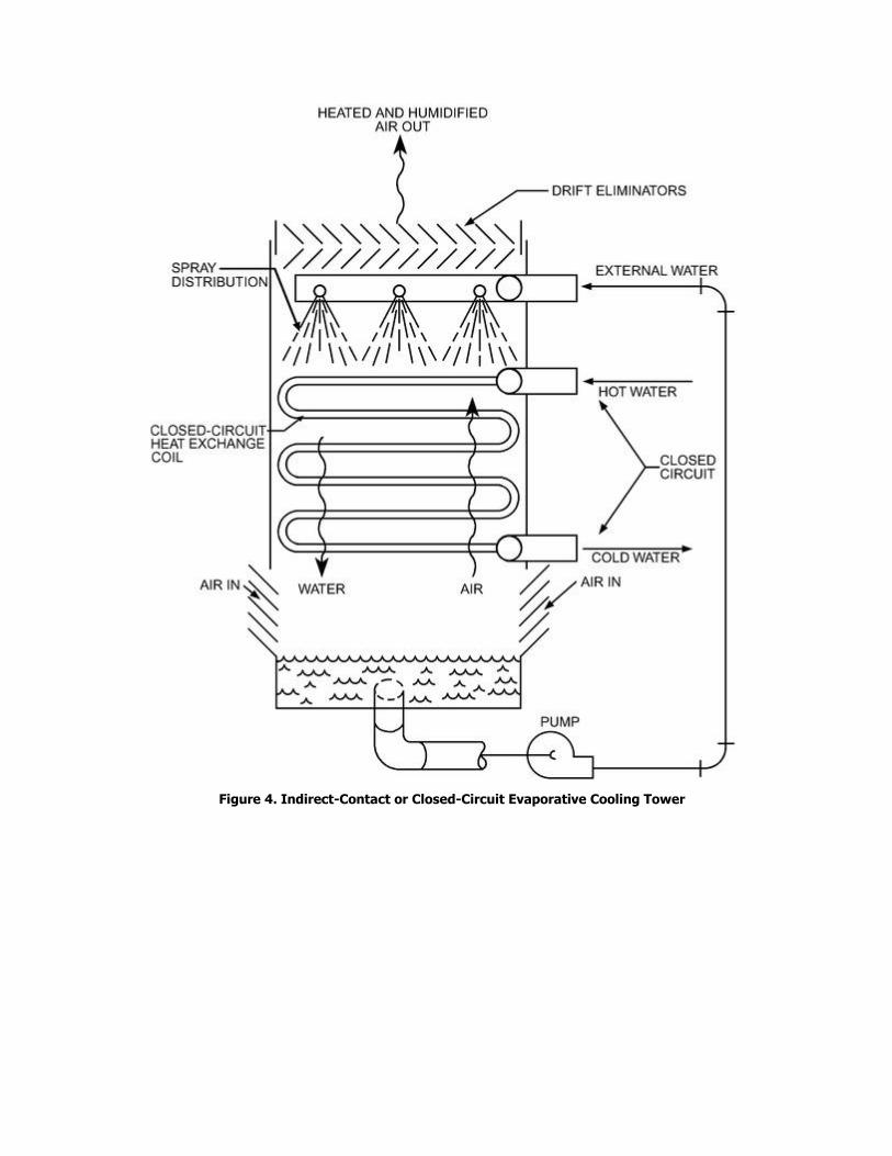
Figure 4. Indirect-Contact or Closed-Circuit Evaporative Cooling Tower
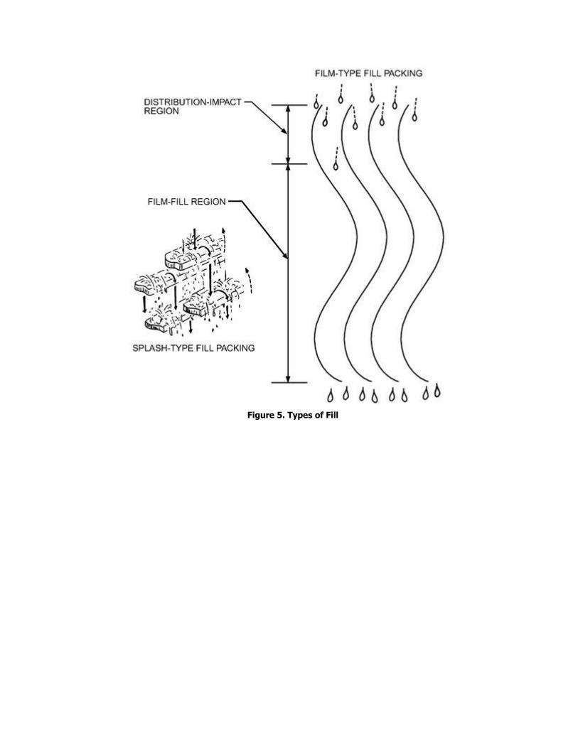
Figure 5. Types of Fill
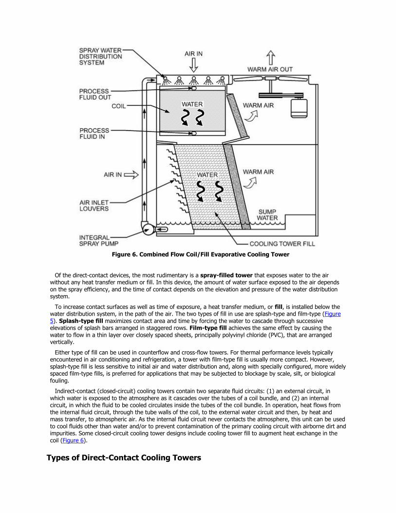
Figure 6. Combined Flow Coil/Fill Evaporative Cooling Tower
Of the direct-contact devices, the most rudimentary is a spray-filled tower that exposes water to the air without any heat transfer medium or fill. In this device, the amount of water surface exposed to the air depends on the spray efficiency, and the time of contact depends on the elevation and pressure of the water distribution system.
To increase contact surfaces as well as time of exposure, a heat transfer medium, or fill, is installed below the water distribution system, in the path of the air. The two types of fill in use are splash-type and film-type (Figure 5). Splash-type fill maximizes contact area and time by forcing the water to cascade through successive elevations of splash bars arranged in staggered rows. Film-type fill achieves the same effect by causing the water to flow in a thin layer over closely spaced sheets, principally polyvinyl chloride (PVC), that are arranged vertically.
Either type of fill can be used in counterflow and cross-flow towers. For thermal performance levels typically encountered in air conditioning and refrigeration, a tower with film-type fill is usually more compact. However, splash-type fill is less sensitive to initial air and water distribution and, along with specially configured, more widely spaced film-type fills, is preferred for applications that may be subjected to blockage by scale, silt, or biological fouling.
Indirect-contact (closed-circuit) cooling towers contain two separate fluid circuits: (1) an external circuit, in which water is exposed to the atmosphere as it cascades over the tubes of a coil bundle, and (2) an internal circuit, in which the fluid to be cooled circulates inside the tubes of the coil bundle. In operation, heat flows from the internal fluid circuit, through the tube walls of the coil, to the external water circuit and then, by heat and mass transfer, to atmospheric air. As the internal fluid circuit never contacts the atmosphere, this unit can be used to cool fluids other than water and/or to prevent contamination of the primary cooling circuit with airborne dirt and impurities. Some closed-circuit cooling tower designs include cooling tower fill to augment heat exchange in the coil (Figure 6).
Types of Direct-Contact Cooling Towers
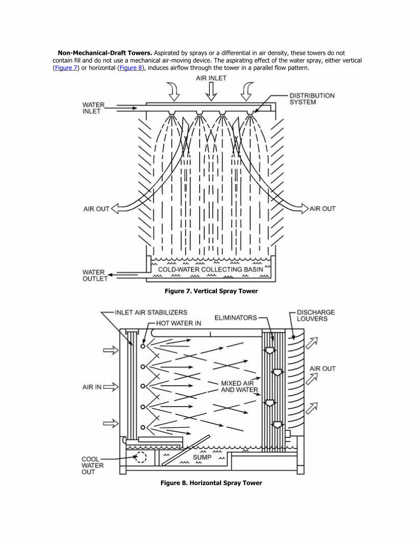
Non-Mechanical-Draft Towers. Aspirated by sprays or a differential in air density, these towers do not
contain fill and do not use a mechanical air-moving device. The aspirating effect of the water spray, either vertical (Figure 7) or horizontal (Figure 8), induces airflow through the tower in a parallel flow pattern.
Figure 7. Vertical Spray Tower
Figure 8. Horizontal Spray Tower
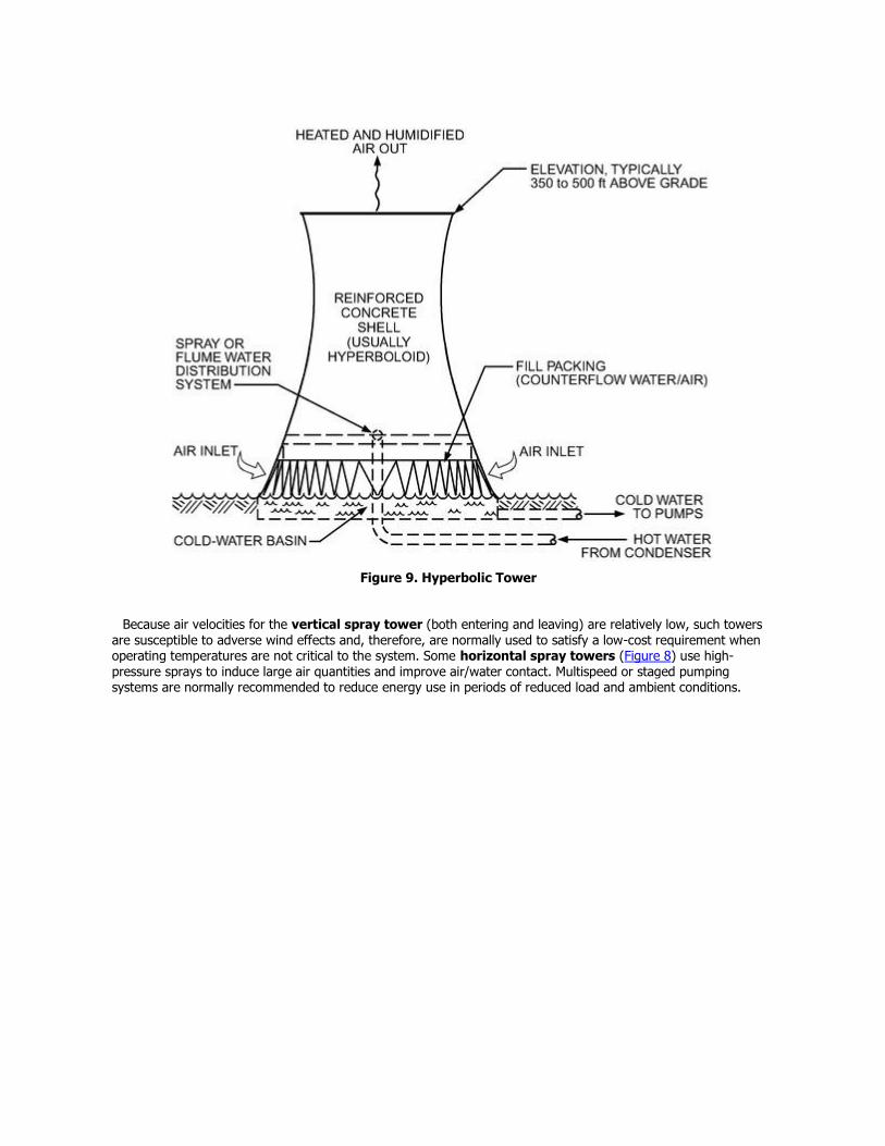
Figure 9. Hyperbolic Tower
Because air velocities for the vertical spray tower (both entering and leaving) are relatively low, such towers are susceptible to adverse wind effects and, therefore, are normally used to satisfy a low-cost requirement when operating temperatures are not critical to the system. Some horizontal spray towers (Figure 8) use high-pressure sprays to induce large air quantities and improve air/water contact. Multispeed or staged pumping systems are normally recommended to reduce energy use in periods of reduced load and ambient conditions.
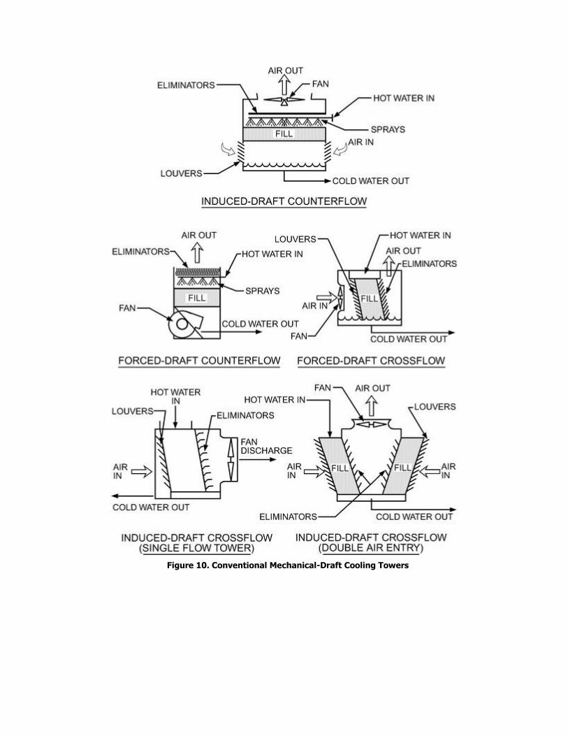
Figure 10. Conventional Mechanical-Draft Cooling Towers
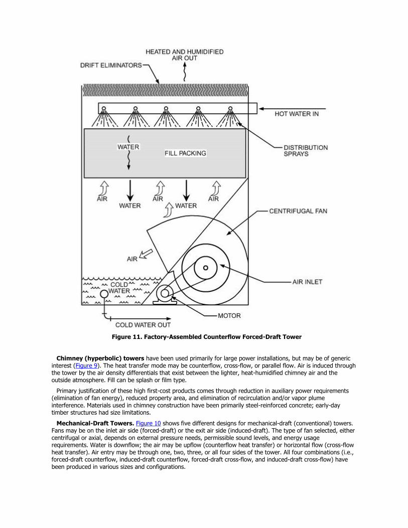
Figure 11. Factory-Assembled Counterflow Forced-Draft Tower
Chimney (hyperbolic) towers have been used primarily for large power installations, but may be of generic interest (Figure 9). The heat transfer mode may be counterflow, cross-flow, or parallel flow. Air is induced through the tower by the air density differentials that exist between the lighter, heat-humidified chimney air and the outside atmosphere. Fill can be splash or film type.
Primary justification of these high first-cost products comes through reduction in auxiliary power requirements (elimination of fan energy), reduced property area, and elimination of recirculation and/or vapor plume
interference. Materials used in chimney construction have been primarily steel-reinforced concrete; early-day timber structures had size limitations.
Mechanical-Draft Towers. Figure 10 shows five different designs for mechanical-draft (conventional) towers. Fans may be on the inlet air side (forced-draft) or the exit air side (induced-draft). The type of fan selected, either centrifugal or axial, depends on external pressure needs, permissible sound levels, and energy usage requirements. Water is downflow; the air may be upflow (counterflow heat transfer) or horizontal flow (cross-flow heat transfer). Air entry may be through one, two, three, or all four sides of the tower. All four combinations (i.e., forced-draft counterflow, induced-draft counterflow, forced-draft cross-flow, and induced-draft cross-flow) have been produced in various sizes and configurations.
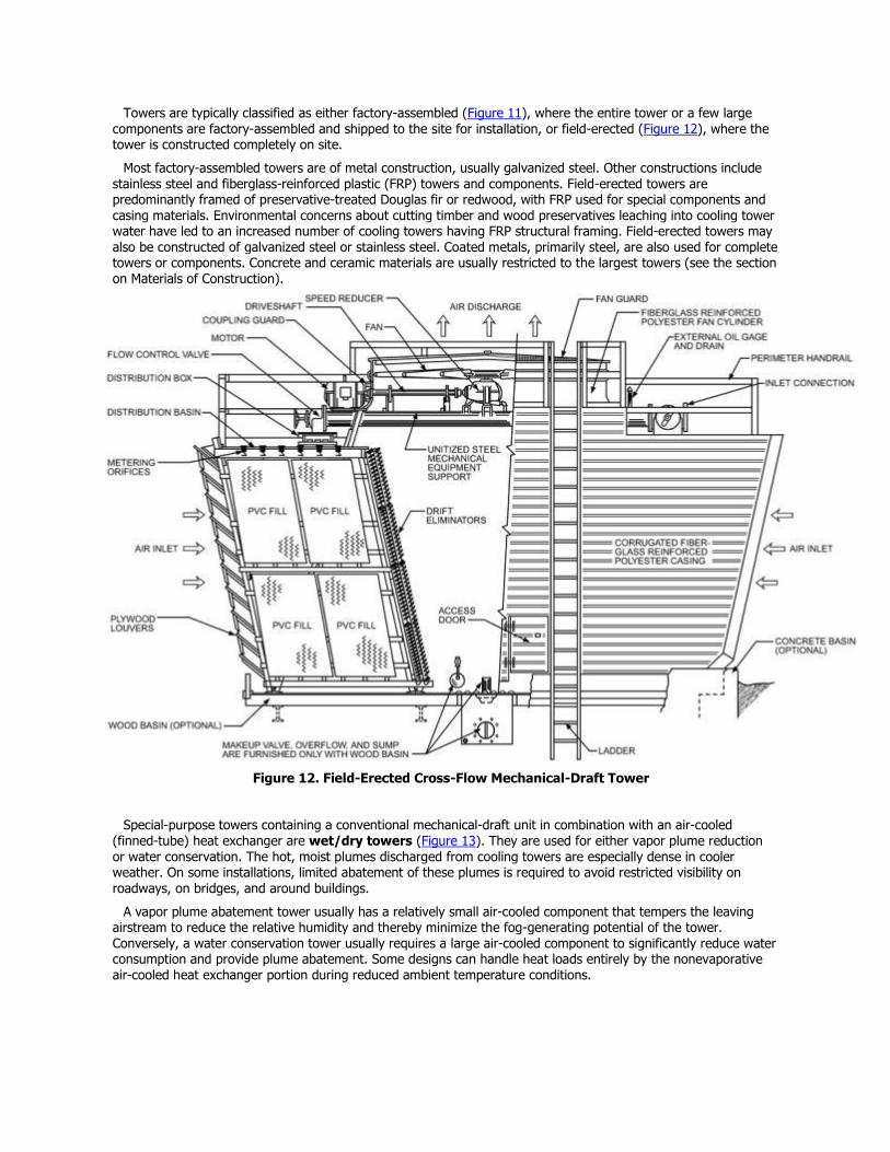
Towers are typically classified as either factory-assembled (Figure 11), where the entire tower or a few large
components are factory-assembled and shipped to the site for installation, or field-erected (Figure 12), where the tower is constructed completely on site.
Most factory-assembled towers are of metal construction, usually galvanized steel. Other constructions include stainless steel and fiberglass-reinforced plastic (FRP) towers and components. Field-erected towers are predominantly framed of preservative-treated Douglas fir or redwood, with FRP used for special components and casing materials. Environmental concerns about cutting timber and wood preservatives leaching into cooling tower water have led to an increased number of cooling towers having FRP structural framing. Field-erected towers may also be constructed of galvanized steel or stainless steel. Coated metals, primarily steel, are also used for complete towers or components. Concrete and ceramic materials are usually restricted to the largest towers (see the section on Materials of Construction).
Figure 12. Field-Erected Cross-Flow Mechanical-Draft Tower
Special-purpose towers containing a conventional mechanical-draft unit in combination with an air-cooled (finned-tube) heat exchanger are wet/dry towers (Figure 13). They are used for either vapor plume reduction or water conservation. The hot, moist plumes discharged from cooling towers are especially dense in cooler weather. On some installations, limited abatement of these plumes is required to avoid restricted visibility on
roadways, on bridges, and around buildings.
A vapor plume abatement tower usually has a relatively small air-cooled component that tempers the leaving airstream to reduce the relative humidity and thereby minimize the fog-generating potential of the tower. Conversely, a water conservation tower usually requires a large air-cooled component to significantly reduce water consumption and provide plume abatement. Some designs can handle heat loads entirely by the nonevaporative air-cooled heat exchanger portion during reduced ambient temperature conditions.
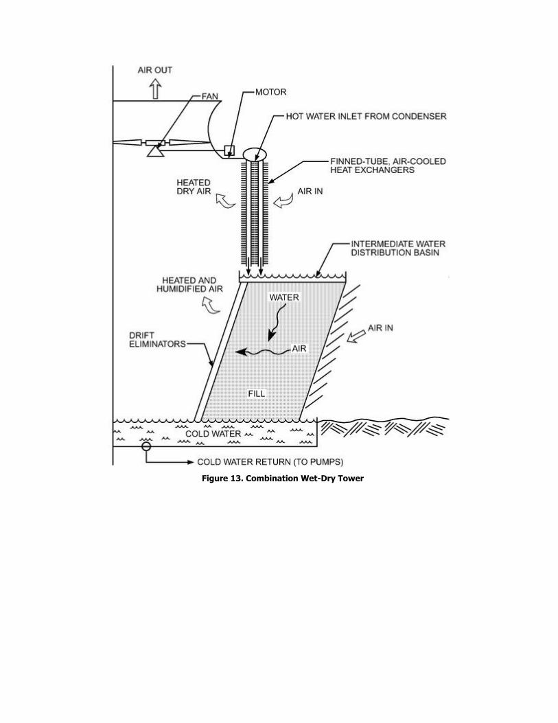
Figure 13. Combination Wet-Dry Tower
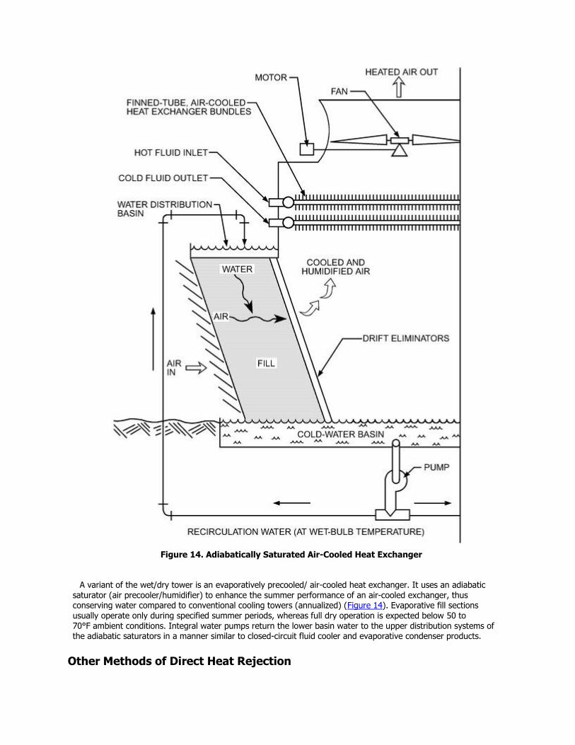
Figure 14. Adiabatically Saturated Air-Cooled Heat Exchanger
A variant of the wet/dry tower is an evaporatively precooled/ air-cooled heat exchanger. It uses an adiabatic saturator (air precooler/humidifier) to enhance the summer performance of an air-cooled exchanger, thus conserving water compared to conventional cooling towers (annualized) (Figure 14). Evaporative fill sections usually operate only during specified summer periods, whereas full dry operation is expected below 50 to 70°F ambient conditions. Integral water pumps return the lower basin water to the upper distribution systems of the adiabatic saturators in a manner similar to closed-circuit fluid cooler and evaporative condenser products.
Other Methods of Direct Heat Rejection
Ponds, Spray Ponds, Spray Module Ponds, and Channels. Heat dissipates from the surface of a body of
water by evaporation, radiation, and convection. Captive lakes or ponds (man-made or natural) are sometimes used to dissipate heat by natural air currents and wind. This system is usually used in large plants where real estate is not limited.
A pump-spray system above the pond surface improves heat transfer by spraying water in small droplets, thereby extending the water surface and bringing it into intimate contact with the air. Heat transfer is largely the result of evaporative cooling (see the section on Cooling Tower Theory). The system is a piping arrangement using branch arms and nozzles to spray circulated water into the air. The pond acts largely as a collecting basin. Temperature control, real estate demands, limited approach to the wet-bulb temperature, and winter operational difficulties have ruled out the spray pond in favor of more compact and more controllable mechanical- or natural-draft towers.
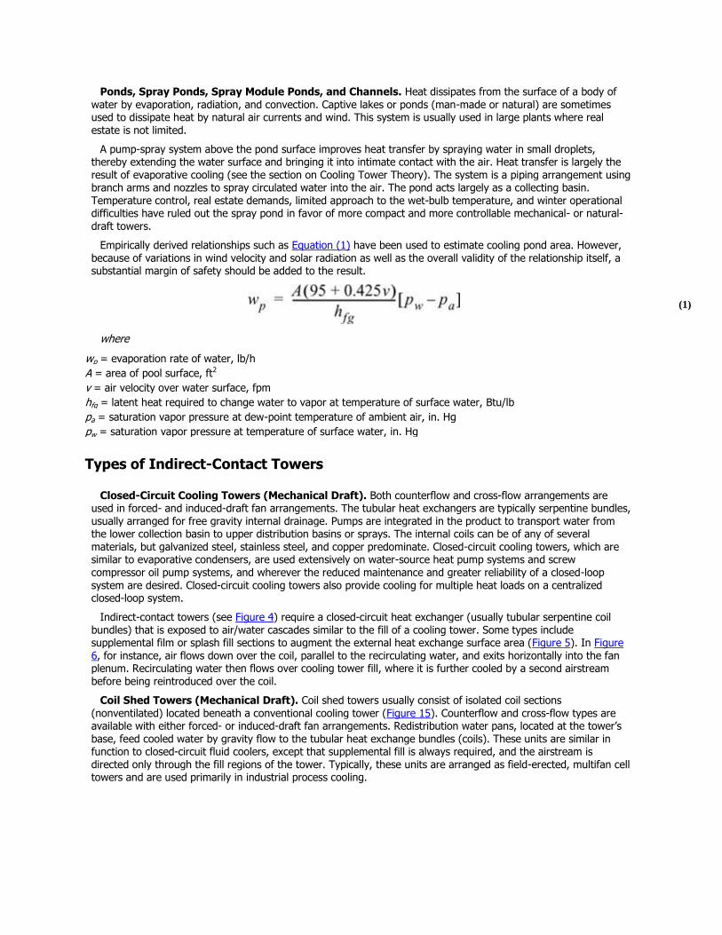
Empirically derived relationships such as Equation (1) have been used to estimate cooling pond area. However, because of variations in wind velocity and solar radiation as well as the overall validity of the relationship itself, a substantial margin of safety should be added to the result.
(1)
where
wp = evaporation rate of water, lb/h
A = area of pool surface, ft2
v = air velocity over water surface, fpm
hfg = latent heat required to change water to vapor at temperature of surface water, Btu/lb
pa = saturation vapor pressure at dew-point temperature of ambient air, in. Hg
pw = saturation vapor pressure at temperature of surface water, in. Hg
Types of Indirect-Contact Towers
Closed-Circuit Cooling Towers (Mechanical Draft). Both counterflow and cross-flow arrangements are used in forced- and induced-draft fan arrangements. The tubular heat exchangers are typically serpentine bundles, usually arranged for free gravity internal drainage. Pumps are integrated in the product to transport water from the lower collection basin to upper distribution basins or sprays. The internal coils can be of any of several materials, but galvanized steel, stainless steel, and copper predominate. Closed-circuit cooling towers, which are similar to evaporative condensers, are used extensively on water-source heat pump systems and screw compressor oil pump systems, and wherever the reduced maintenance and greater reliability of a closed-loop system are desired. Closed-circuit cooling towers also provide cooling for multiple heat loads on a centralized closed-loop system.
Indirect-contact towers (see Figure 4) require a closed-circuit heat exchanger (usually tubular serpentine coil bundles) that is exposed to air/water cascades similar to the fill of a cooling tower. Some types include supplemental film or splash fill sections to augment the external heat exchange surface area (Figure 5). In Figure 6, for instance, air flows down over the coil, parallel to the recirculating water, and exits horizontally into the fan plenum. Recirculating water then flows over cooling tower fill, where it is further cooled by a second airstream before being reintroduced over the coil.
Coil Shed Towers (Mechanical Draft). Coil shed towers usually consist of isolated coil sections
(nonventilated) located beneath a conventional cooling tower (Figure 15). Counterflow and cross-flow types are available with either forced- or induced-draft fan arrangements. Redistribution water pans, located at the tower’s base, feed cooled water by gravity flow to the tubular heat exchange bundles (coils). These units are similar in function to closed-circuit fluid coolers, except that supplemental fill is always required, and the airstream is directed only through the fill regions of the tower. Typically, these units are arranged as field-erected, multifan cell towers and are used primarily in industrial process cooling.
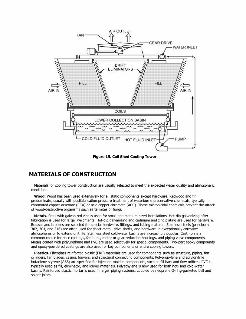
Figure 15. Coil Shed Cooling Tower
MATERIALS OF CONSTRUCTION
Materials for cooling tower construction are usually selected to meet the expected water quality and atmospheric conditions.
Wood. Wood has been used extensively for all static components except hardware. Redwood and fir predominate, usually with postfabrication pressure treatment of waterborne preservative chemicals, typically chromated copper arsenate (CCA) or acid copper chromate (ACC). These microbicidal chemicals prevent the attack of wood-destructive organisms such as termites or fungi.
Metals. Steel with galvanized zinc is used for small and medium-sized installations. Hot-dip galvanizing after fabrication is used for larger weldments. Hot-dip galvanizing and cadmium and zinc plating are used for hardware. Brasses and bronzes are selected for special hardware, fittings, and tubing material. Stainless steels (principally 302, 304, and 316) are often used for sheet metal, drive shafts, and hardware in exceptionally corrosive atmospheres or to extend unit life. Stainless steel cold-water basins are increasingly popular. Cast iron is a common choice for base castings, fan hubs, motor or gear reduction housings, and piping valve components. Metals coated with polyurethane and PVC are used selectively for special components. Two-part epoxy compounds and epoxy-powdered coatings are also used for key components or entire cooling towers.
Plastics. Fiberglass-reinforced plastic (FRP) materials are used for components such as structure, piping, fan cylinders, fan blades, casing, louvers, and structural connecting components. Polypropylene and acrylonitrile butadiene styrene (ABS) are specified for injection-molded components, such as fill bars and flow orifices. PVC is typically used as fill, eliminator, and louver materials. Polyethylene is now used for both hot- and cold-water basins. Reinforced plastic mortar is used in larger piping systems, coupled by neoprene O-ring-gasketed bell and spigot joints.
Graphite Composites. Graphite composite drive shafts are available for use on cooling tower installations.
These shafts offer a strong, corrosion-resistant alternative to steel/stainless steel shafts and are often less expensive, more forgiving of misalignment, and transmit less vibration.
Concrete, Masonry, and Tile. Concrete is typically specified for cold-water basins of field-erected cooling towers and is used in piping, casing, and structural systems of the largest towers, primarily in the power and process industries. Special tiles and masonry are used when aesthetic considerations are important.
SELECTION CONSIDERATIONS
Selecting the proper water-cooling equipment for a specific application requires consideration of cooling duty, economics, required services, environmental conditions, maintenance requirements, and aesthetics. Many of these factors are interrelated, but they should be evaluated individually.
Because a wide variety of water-cooling equipment may meet the required cooling duty, factors such as height, length, width, volume of airflow, fan and pump energy consumption, materials of construction, water quality, and availability influence final equipment selection.
The optimum choice is generally made after an economic evaluation. Chapter 37 of the ASHRAE Handbook—HVAC Applications describes two common methods of economic evaluation—life-cycle costing and payback analysis. Each of these procedures compares equipment on the basis of total owning, operating, and maintenance costs.
Initial-cost comparisons consider the following factors:
Erected cost of equipment
Costs of interface with other subsystems, which include items such as
o Basin grillage and value of the space occupied
o Pumps and prime movers
o Electrical wiring to pump and fan motors
o Electrical controls and switchgear
o Piping to and from the tower (some designs require more inlet and discharge connections than others, thus affecting the cost of piping)
o Tower basin, sump screens, overflow piping, and makeup lines, if not furnished by the manufacturer
o Shutoff and control valves, if not furnished by the manufacturer
o Walkways, ladders, etc., providing access to the tower, if not furnished by the manufacturer
o Fire protection sprinkler system
In evaluating owning and maintenance costs, consider the following major items:
System energy costs (fans, pumps, etc.) on the basis of operating hours per year
Energy demand charges
Expected equipment life
Maintenance and repair costs
Money costs
Other factors are (1) safety features and safety codes; (2) conformity to building codes; (3) general design and rigidity of structures; (4) relative effects of corrosion, scale, or deterioration on service life; (5) availability of spare parts; (6) experience and reliability of manufacturers; (7) independent certification of thermal ratings; and (8) operating flexibility for economical operation at varying loads or during seasonal changes. In addition, equipment vibration, sound levels, acoustical attenuation, and compatibility with the architectural design are important. The following section details many of these more important considerations.
APPLICATION
This section describes some of the major design considerations, but the cooling tower manufacturer should be consulted for more detailed recommendations.
Siting
When a cooling tower can be located in an open space with free air motion and unimpeded air supply, siting is normally not an obstacle to satisfactory installation. However, towers are often situated indoors, against walls, or in enclosures. In such cases, the following factors must be considered:
Sufficient free and unobstructed space should be provided around the unit to ensure an adequate air supply to the fans and to allow proper servicing.
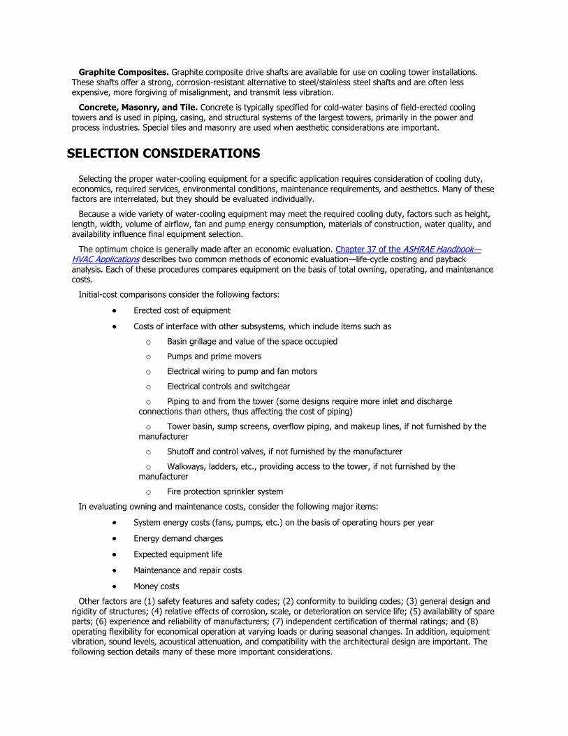
Tower discharge air should not be deflected in any way that might promote recirculation [a portion of the warm, moist discharge air reentering the tower (Figure 16)]. Recirculation raises the entering wet-bulb temperature, causing increased hot water and cold water temperatures, and, during cold weather operation, can promote the icing of air intake areas. The possibility of air recirculation should be considered, particularly on multiple-tower installations.
Additionally, cooling towers should be located to prevent introducing the warm discharge air and any associated drift, which may contain chemical and/or biological contaminants, into the fresh air intake of the building that the tower is serving or into those of adjacent buildings.
Figure 16. Discharge Air Reentering Tower
Location of the cooling tower is usually determined by one or more of the following: (1) structural support requirements, (2) rigging limitations, (3) local codes and ordinances, (4) cost of bringing auxiliary services to the
cooling tower, and (5) architectural compatibility. Sound, plume, and drift considerations are also best handled by proper site selection during the planning stage. For additional information on seismic and wind restraint, see Chapter 55 of theASHRAE Handbook—HVAC Applications.
Piping
Piping should be adequately sized according to standard commercial practice. All piping should be designed to allow expansion and contraction. If the tower has more than one inlet connection, balancing valves should be installed to balance the flow to each cell properly. Positive shutoff valves should be used, if necessary, to isolate individual cells for servicing.
When two or more towers operate in parallel, an equalizer line between the tower sumps handles imbalances in
the piping to and from the units and changing flow rates that arise from obstructions such as clogged orifices and strainers. All heat exchangers, and as much tower piping as possible, should be installed below the operating water level in the cooling tower to prevent overflowing of the cooling tower at shutdown and to ensure satisfactory pump operation during start-up. Tower basins must carry the proper amount of water during operation to prevent air entrainment into the water suction line. Tower basins should also have enough reserve volume between the operating and overflow levels to fill riser and water distribution lines on start-up and to fulfill the water-in-suspension requirement of the tower. Unlike open towers, closed-circuit cooling towers can be installed anywhere, even below the heat exchangers, as the fluid to be cooled is contained in a closed loop; the external spray water is self-contained within the closed-circuit cooling tower.
Capacity Control
Most cooling towers encounter substantial changes in ambient wet-bulb temperature and load during the normal operating season. Accordingly, some form of capacity control may be required to maintain prescribed condensing temperatures or process conditions.
Fan cycling is the simplest method of capacity control on cooling towers and is often used on multiple-unit or multiple-cell installations. In nonfreezing climates, where close control of the exit water temperature is not essential, fan cycling is an adequate and inexpensive method of capacity control. However, motor burnout from too-frequent cycling is a concern.
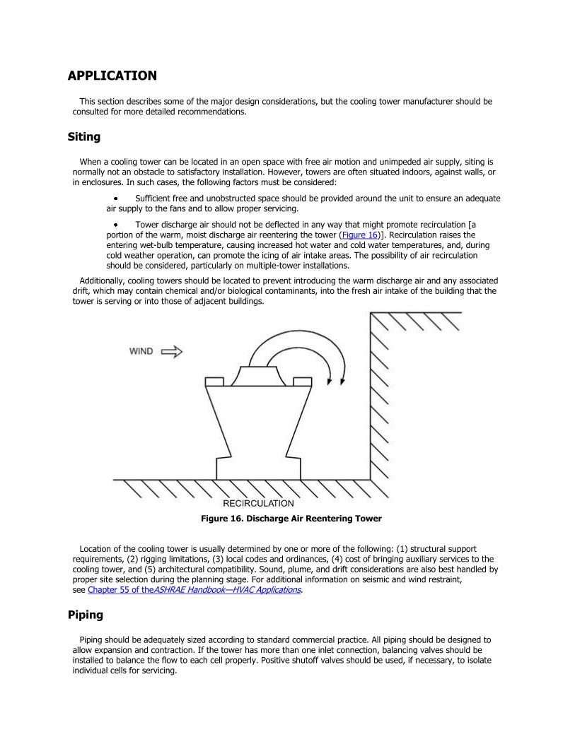
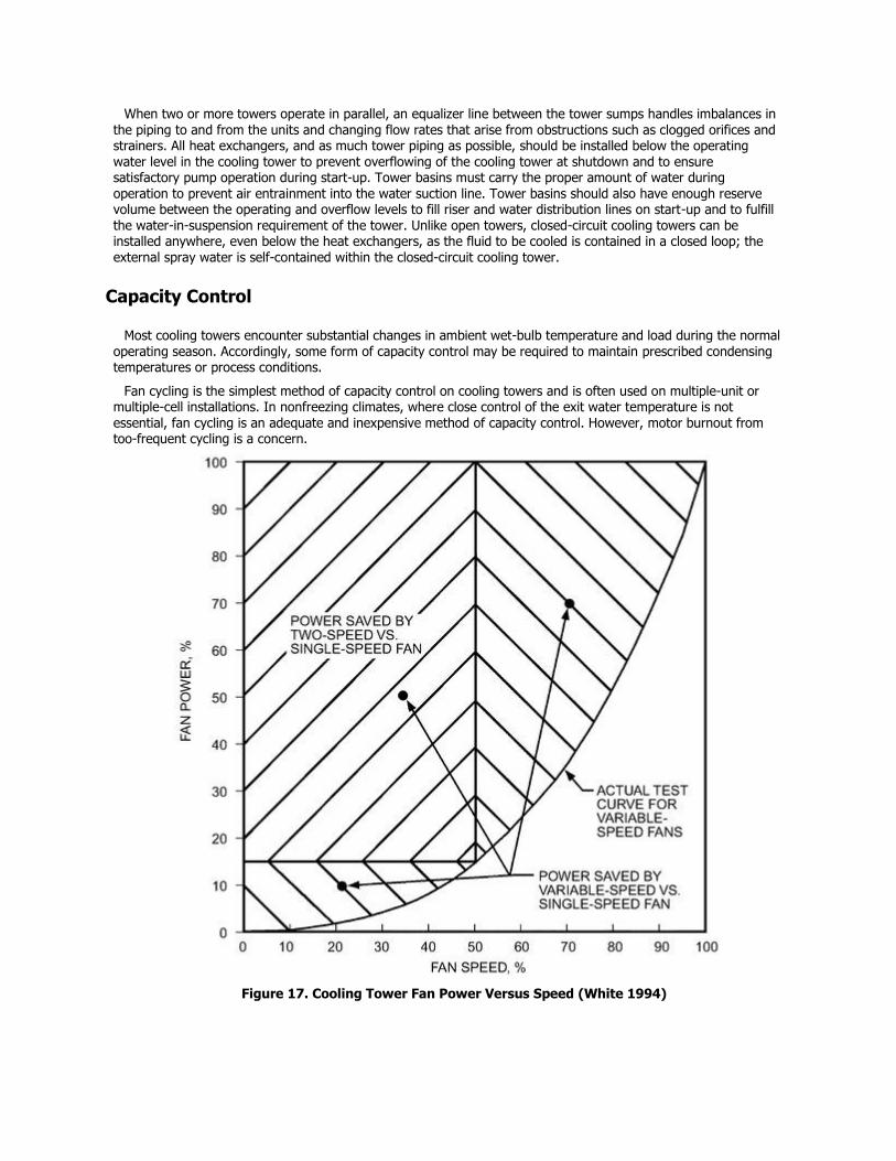
Figure 17. Cooling Tower Fan Power Versus Speed (White 1994)
Two-speed fan motors or additional lower-power pony motors, in conjunction with fan cycling, can double the
number of steps of capacity control compared to fan cycling alone. This is particularly useful on single-fan motor units, which would have only one step of capacity control by fan cycling. Two-speed fan motors are commonly used on cooling towers as the primary method of capacity control, and provide the added advantage of reduced energy consumption at reduced load. Pony motors also provide some redundancy in case one motor fails.
It is more economical to operate all fans at the same speed than to operate one fan at full speed before starting the next. Figure 17 compares cooling tower fan power versus speed for single-, two-, and variable-speed fan motors.
Frequency-modulating controls for fan motor speed can provide virtually infinite capacity control and energy management. Previously, automatic, variable-pitch propeller fans were the only way to do this; however, these mechanically complex drive systems are more expensive and have higher sound levels, because they operate at full design speed only. They have largely been replaced by variable-frequency drives (VFDs) coupled with a standard fixed-pitch fan, thereby saving more fan energy and operating significantly more quietly when the tower is at less than full load.
Variable-frequency fan drives are economical and can save considerable energy as well as extend the life of the motor, fan, and drive (gearbox or V-belt) assembly compared to fan cycling with two-speed control. However, special considerations that should be discussed with the tower manufacturer and the supplier of the VFD include the following:
Care must be taken to avoid operating the fan system at a critical speed or a multiple thereof. Critical speedsare fan operating speeds identical to one of the natural frequencies of the fan assembly and/or supporting structure. At these speeds, fan resonance occurs, resulting in excessive vibration and possibly fan system failure, sometimes very quickly. Consult the tower manufacturer on what speeds (if any) must be avoided. Alternatively, the tower can be tested at start-up using an accelerometer to identify critical frequencies throughout the full speed range, thought this is generally not necessary with pre-engineered, factory-assembled units. Critical frequencies, identified either by the manufacturer or through actual testing, must be locked out in the VFD skip frequency program.
Some VFDs, particularly pulse-width modulating (PWM) drives, create overvoltages at the motor that can cause motor and bearing failures. The magnitude of these overvoltages increases significantly with the length of cable between the controller and the motor, so lead lengths should be kept as short as possible. Special motors, filters, or other corrective measures may be necessary to ensure dependable operation. Consult the cooling tower manufacturer and/or the VFD supplier. Chapter 44 also has more information on variable-frequency drives.
A VFD-compatible motor should be specified on all cooling towers with variable-frequency drives.
Variable-frequency drives should not be operated at speeds below approximately 25% of the full design fan speed. Although most VFDs can modulate down to 10% or less of motor speed, a 25% lower limit is recommended to maintain proper air and water distribution. At very low airflow rates, the water and air can channel into separate streams, especially in counterflow units where uniform water distribution may depend on the airflow rate. Uneven water distribution can lead to wet/dry areas and scaling. In freezing climates, these separate streams could also result in localized ice formation. Additionally, the fan energy saving at 10% compared to 25% of full design speed is typically insignificant.
This precaution is particularly true for units with gear speed reducers because low speeds can cause rotational ―cogging,‖ vibration, noise or ―gear chatter,‖ and pose a lubrication problem if the gear is either not equipped with an electric oil pump or not specifically designed to run at these low speeds. Consult the tower manufacturer for proper selection and adjustments of the VFD.
Modulating dampers in the discharge of centrifugal blower fans are also used for cooling tower capacity control, as well as for energy management. In some cases, modulating dampers may be used with two-speed motors. Note that modulating dampers have increasingly been replaced by variable-frequency drives for these purposes.
Cooling towers that inject water to induce airflow through the cooling tower have various pumping arrangements for capacity control. Multiple pumps in series or two-speed pumping provide capacity control and also reduce energy consumption.
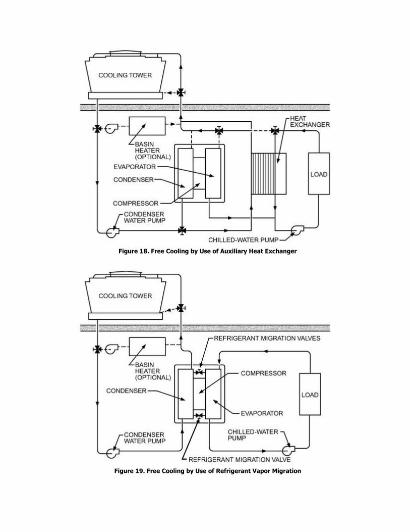
Figure 18. Free Cooling by Use of Auxiliary Heat Exchanger
Figure 19. Free Cooling by Use of Refrigerant Vapor Migration
Modulating water bypasses for capacity control should be used only after consultation with the cooling tower manufacturer. This is particularly important at low ambient conditions in which the reduced water flows can promote freezing within the tower.
Water-Side Economizer (Free Cooling)
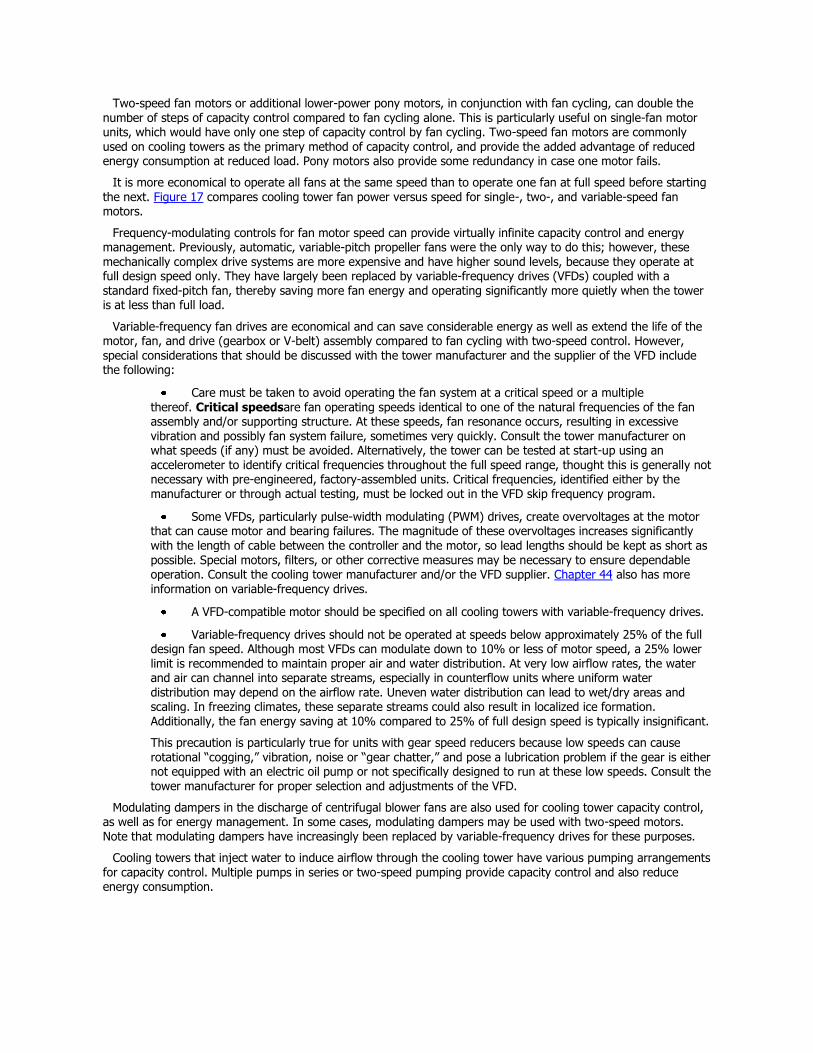
With an appropriately equipped and piped system, using the tower for free cooling during reduced load and/or reduced ambient conditions can significantly reduce system energy consumption. Because the tower’s cold-water temperature drops as the load and ambient temperature drop, the water temperature will eventually be low enough to serve the load directly, allowing the energy-intensive chiller to be shut off. Figures 18, 19, and 20 outline three methods of free cooling but do not show all of the piping, valving, and controls that may be necessary for the functioning of a specific system.
Maximum use of free-cooling operation occurs when a drop in the ambient temperature reduces the need for dehumidification. Therefore, higher temperatures in the chilled-water circuit can normally be tolerated during the
free-cooling season and are beneficial to the system’s heating/cooling balance. In many cases, typical 45°F chilled water temperatures are allowed to rise to 55°F or higher in free cooling. This maximizes tower usage and minimizes system energy consumption. Some applications require a constant chilled-water supply temperature, which can reduce the hours of free cooling operation, depending on ambient temperatures.
If the spray water temperature is allowed to fall too low, freezing may be a concern. Close control of spray water temperature per the manufacturer’s recommendations minimizes unit icing and helps ensure trouble-free operation. Refer to the guidelines from the manufacturer and to the section on Winter Operation in this chapter.
Indirect Free Cooling. This type of cooling separates the condenser-water and chilled-water circuits and may be accomplished in the following ways:
1. A separate heat exchanger in the system (usually plate-and-frame) allows heat to transfer from the chilled-water circuit to the condenser-water circuit by total bypass of the chiller system (Figure 18).
2. An indirect-contact, closed-circuit evaporative cooling tower (Figures 4 and 6) also permits indirect free cooling. Its use is covered in the following section on Direct Free Cooling.
3. In vapor migration system (Figure 19), bypasses between the evaporator and condenser permit
migratory flow of refrigerant vapor to the condenser; they also allow gravity flow of liquid refrigerant back to the evaporator without compressor operation. Not all chiller systems are adaptable to this arrangement, and those that are may offer limited load capability under this mode. In some cases, auxiliary pumps enhance refrigerant flow and, therefore, load capability.
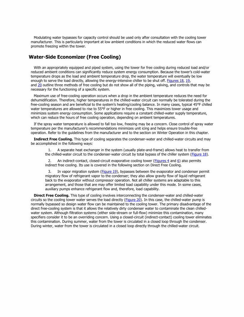
Direct Free Cooling. This type of cooling involves interconnecting the condenser-water and chilled-water circuits so the cooling tower water serves the load directly (Figure 20). In this case, the chilled-water pump is normally bypassed so design water flow can be maintained to the cooling tower. The primary disadvantage of the direct free-cooling system is that it allows the relatively dirty condenser water to contaminate the clean chilled-water system. Although filtration systems (either side-stream or full-flow) minimize this contamination, many specifiers consider it to be an overriding concern. Using a closed-circuit (indirect-contact) cooling tower eliminates this contamination. During summer, water from the tower is circulated in a closed loop through the condenser. During winter, water from the tower is circulated in a closed loop directly through the chilled-water circuit.
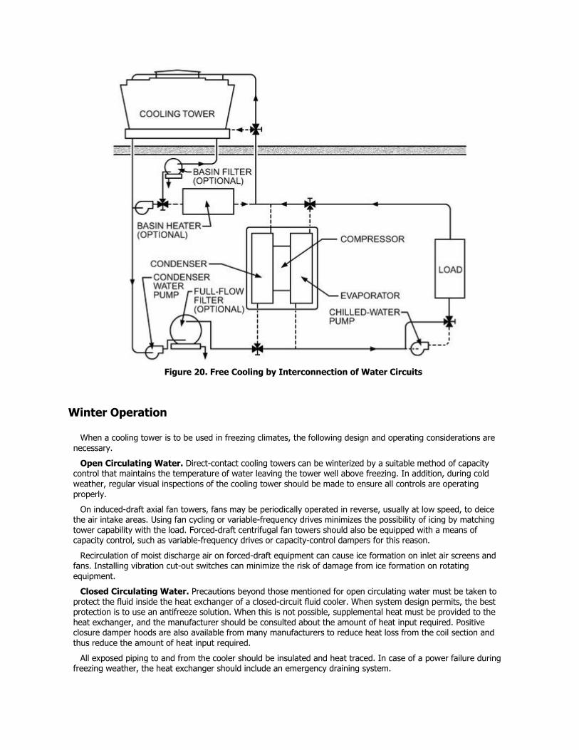
Figure 20. Free Cooling by Interconnection of Water Circuits
Winter Operation
When a cooling tower is to be used in freezing climates, the following design and operating considerations are necessary.
Open Circulating Water. Direct-contact cooling towers can be winterized by a suitable method of capacity control that maintains the temperature of water leaving the tower well above freezing. In addition, during cold weather, regular visual inspections of the cooling tower should be made to ensure all controls are operating properly.
On induced-draft axial fan towers, fans may be periodically operated in reverse, usually at low speed, to deice the air intake areas. Using fan cycling or variable-frequency drives minimizes the possibility of icing by matching tower capability with the load. Forced-draft centrifugal fan towers should also be equipped with a means of capacity control, such as variable-frequency drives or capacity-control dampers for this reason.
Recirculation of moist discharge air on forced-draft equipment can cause ice formation on inlet air screens and fans. Installing vibration cut-out switches can minimize the risk of damage from ice formation on rotating
equipment.
Closed Circulating Water. Precautions beyond those mentioned for open circulating water must be taken to protect the fluid inside the heat exchanger of a closed-circuit fluid cooler. When system design permits, the best protection is to use an antifreeze solution. When this is not possible, supplemental heat must be provided to the heat exchanger, and the manufacturer should be consulted about the amount of heat input required. Positive closure damper hoods are also available from many manufacturers to reduce heat loss from the coil section and thus reduce the amount of heat input required.
All exposed piping to and from the cooler should be insulated and heat traced. In case of a power failure during freezing weather, the heat exchanger should include an emergency draining system.
Sump Water. Freeze protection for the sump water in an idle tower or closed-circuit fluid cooler can be
obtained by various means. A good method is to use an auxiliary sump tank located in a heated space. When a remote sump is impractical, auxiliary heat must be supplied to the tower sump to prevent freezing. Common sources are electric immersion heaters and steam and hot-water coils. Consult the tower manufacturer for the exact heat requirements to prevent freezing at design winter temperatures.
All exposed water lines susceptible to freezing should be protected by electric heat tape or cable and insulation. This precaution applies to all lines or portions of lines that have water in them when the tower is shut down.
Sound
Sound has become an important consideration in the selection and siting of outdoor equipment such as cooling towers and other evaporative cooling devices. Many communities have enacted legislation that limits allowable sound levels of outdoor equipment. Even if legislation does not exist, people who live and work near a tower installation may object if the sound intrudes on their environment. Because the cost of correcting a sound problem may exceed the original cost of the cooling tower, sound should be considered in the early stages of system design.
To determine the acceptability of tower sound in a given environment, the first step is to establish a noise criterion for the area of concern. This may be an existing or pending code or an estimate of sound levels that will be acceptable to those living or working in the area. The second step is to estimate the sound levels generated by the tower at the critical area, taking into account the effects of the tower installation geometry and the distance from the tower to the critical area. Often, the tower manufacturer can supply sound rating data on a specific unit that serve as the basis for this estimate. Lastly, the noise criterion is compared to the estimated tower sound levels to determine the acceptability of the installation.
In cases where the installation may present a sound problem, several potential solutions are available. It is good practice to situate the tower as far as possible from any sound-sensitive areas. Two-speed fan motors should be considered to reduce tower sound levels (by a nominal 12 dB) during light-load periods, such as at night, if these correspond to critical sound-sensitive periods. However, fan motor cycling should be held to a minimum because a fluctuating sound is usually more objectionable than a constant sound. Using variable-frequency drives can also reduce noise by matching fan speed to capacity and by minimizing sound fluctuation caused by fan cycling.
In critical situations, effective solutions may include barrier walls between the tower and the sound-sensitive area, acoustical treatment of the tower, or using low-sound fans. Attenuators specifically designed for the tower are available from most manufacturers. It may be practical to install a tower larger than would normally be required and lower the sound levels by operating the unit at reduced fan speed. For additional information on sound control, see Chapter 48 of the ASHRAE Handbook—HVAC Applications.
Drift
Water droplets become entrained in the airstream as it passes through the tower. Although eliminators strip most of this water from the discharge airstream, some discharges from the tower as drift. The rate of drift loss from a tower is a function of tower configuration, eliminator design, airflow rate through the tower, and water loading. Generally, an efficient eliminator design reduces drift loss to between 0.001 and 0.005% of the water circulation rate.
Because drift contains the minerals of the makeup water (which may be concentrated three to five times) and often contains water treatment chemicals, cooling towers should not be placed near parking areas, large windowed areas, or architectural surfaces sensitive to staining or scale deposits.
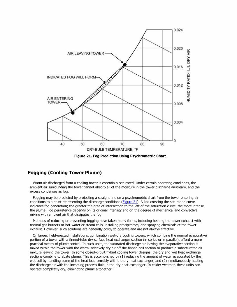
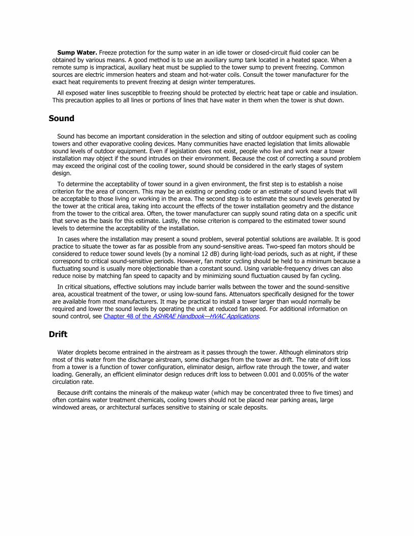
Figure 21. Fog Prediction Using Psychrometric Chart
Fogging (Cooling Tower Plume)
Warm air discharged from a cooling tower is essentially saturated. Under certain operating conditions, the ambient air surrounding the tower cannot absorb all of the moisture in the tower discharge airstream, and the excess condenses as fog.
Fogging may be predicted by projecting a straight line on a psychrometric chart from the tower entering air conditions to a point representing the discharge conditions (Figure 21). A line crossing the saturation curve indicates fog generation; the greater the area of intersection to the left of the saturation curve, the more intense the plume. Fog persistence depends on its original intensity and on the degree of mechanical and convective mixing with ambient air that dissipates the fog.
Methods of reducing or preventing fogging have taken many forms, including heating the tower exhaust with natural gas burners or hot-water or steam coils, installing precipitators, and spraying chemicals at the tower exhaust. However, such solutions are generally costly to operate and are not always effective.
On larger, field-erected installations, combination wet-dry cooling towers, which combine the normal evaporative portion of a tower with a finned-tube dry surface heat exchanger section (in series or in parallel), afford a more practical means of plume control. In such units, the saturated discharge air leaving the evaporative section is mixed within the tower with the warm, relatively dry air off the finned-coil section to produce a subsaturated air mixture leaving the tower. In some closed-circuit hybrid cooling tower designs, the dry and wet heat exchange sections combine to abate plume. This is accomplished by (1) reducing the amount of water evaporated by the wet coil by handling some of the heat load sensibly with the dry heat exchanger, and (2) simultaneously heating the discharge air with the incoming process fluid in the dry heat exchanger. In colder weather, these units can operate completely dry, eliminating plume altogether.
Often, however, the most practical solution to tower fogging is to locate the tower where visible plumes, should
they form, will not be objectionable. Accordingly, when selecting cooling tower sites, the potential for fogging and its effect on tower surroundings, such as large windowed areas or traffic arteries, should be considered.
Maintenance
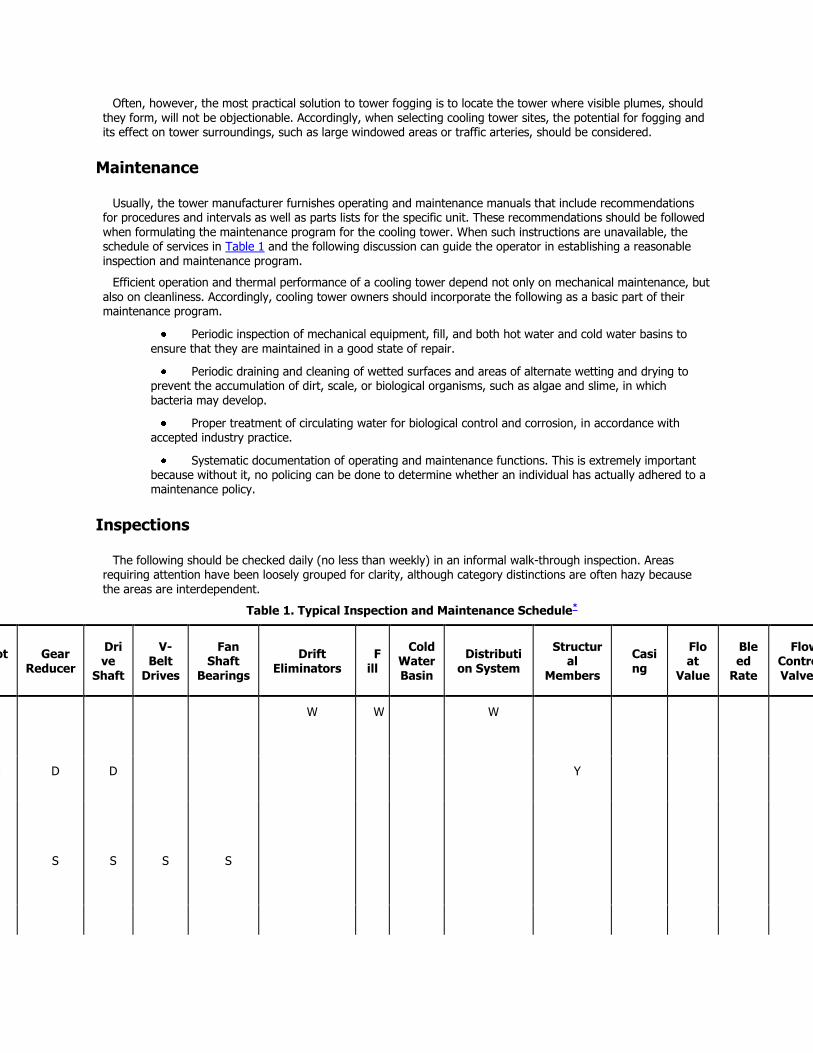
Usually, the tower manufacturer furnishes operating and maintenance manuals that include recommendations for procedures and intervals as well as parts lists for the specific unit. These recommendations should be followed when formulating the maintenance program for the cooling tower. When such instructions are unavailable, the schedule of services in Table 1 and the following discussion can guide the operator in establishing a reasonable inspection and maintenance program.
Efficient operation and thermal performance of a cooling tower depend not only on mechanical maintenance, but also on cleanliness. Accordingly, cooling tower owners should incorporate the following as a basic part of their maintenance program.
Periodic inspection of mechanical equipment, fill, and both hot water and cold water basins to
ensure that they are maintained in a good state of repair.
Periodic draining and cleaning of wetted surfaces and areas of alternate wetting and drying to prevent the accumulation of dirt, scale, or biological organisms, such as algae and slime, in which bacteria may develop.
Proper treatment of circulating water for biological control and corrosion, in accordance with accepted industry practice.
Systematic documentation of operating and maintenance functions. This is extremely important because without it, no policing can be done to determine whether an individual has actually adhered to a maintenance policy.
Inspections
The following should be checked daily (no less than weekly) in an informal walk-through inspection. Areas requiring attention have been loosely grouped for clarity, although category distinctions are often hazy because the areas are interdependent.
Table 1. Typical Inspection and Maintenance Schedule*
F
an Motor
Gear Reducer
Drive
Shaft
V-Belt
Drives
Fan Shaft
Bearings
Drift Eliminators
Fill
Cold Water Basin
Distribution System
Structural
Members
Casing
Float
Value
Bleed
Rate
Flow Control Valves
Suction
Screen
1.
Inspect for clogging
W W
W
W
2.
Check for unusual
D D D D
Y
noise or
vibration
3.
Inspect keys and set
S S S S S
screws
F
an Motor
Gear Reducer
Drive
Shaft
V-Belt
Drives
Fan Shaft
Bearings
Drift Eliminators
Fill
Cold Water Basin
Distribution System
Structural
Members
Casing
Float
Value
Bleed
Rate
Flow Control Valves
Suction
Screen
4.
Lubricate
Q
Q
S
5.
Check oil seals
S
6.
Check oil level
W
7.
Check oil for water and dirt
M
8.
Change oil (at least)
S
9.
Adjust tension
M
10.
Check water level
W W
11.
Check flow rate
M
12.
Check for leakage
S S
S
13.
Inspect general condition
S M
Y Y Y
S Y Y
S
14.
Tighten loose bolts
S S S S
S
Y R
15.
Clean R S R R
R R S R
R
R W
16.
Repaint R R R R
R
R R
17.
Completely open and close
S
18.
Make sure vents are open
M
D—daily; W—
F
an Motor
Gear Reducer
Drive
Shaft
V-Belt
Drives
Fan Shaft
Bearings
Drift Eliminators
Fill
Cold Water Basin
Distribution System
Structural
Members
Casing
Float
Value
Bleed
Rate
Flow Control Valves
Suction
Screen
weekly; M—monthly; Q—quarterly; S—semiannually; Y—yearly; R—as required.
* More frequent inspections and maintenance may be
desirable.
Performance. Optimum performance and safety depend on the operation of each individual component at its designed capability. A single blocked strainer, for instance, can adversely affect the capacity and efficiency of the entire system. Operators should always be alert to any degradation in performance, as this usually is the first sign of a problem and is invaluable in pinpointing minor problems before they become major. Consult the equipment manufacturers to obtain specific information on each piece of equipment (for both maintenance and technical characteristics), and keep manuals handy for quick reference.
Check and record all water and refrigerant temperatures, pump pressures, outdoor conditions, and pressure drops (differential pressure) across condensers, heat exchangers and filtration devices. This record helps operators become familiar with the equipment as it operates under various load conditions and provides a permanent record that can be used to calculate flow rates, assess equipment efficiency, expedite diagnostic procedures, and adjust maintenance and water treatment regimens to obtain maximum performance from the system.
For those units with water-side economizers using plate heat exchangers, check temperature and pressure differentials daily for evidence of clogging or fouling.
Major Mechanical Components. During tower inspections, be alert for any unusual noise or vibration from pumps, motors, fans, and other mechanical equipment. This is often the first sign of mechanical trouble. Operators thoroughly familiar with their equipment generally have little trouble recognizing unusual conditions. Also listen for cavitation noises from pumps, which can indicate blocked strainers.
Check the tower fan and drive system assembly for loose mounting hardware, condition of fasteners, grease and oil leaks, and noticeable vibration or wobble when the fan is running. Excessive vibration can rapidly deteriorate the tower.
Observe at least one fan start and stop each week. If a fan has a serious problem, lock it out of operation and call for expert assistance. To be safe, do not take chances by running defective fans.
Fan and drive systems should be professionally checked for dynamic balance, alignment, proper fan pitch (if adjustable), and vibration whenever major repair work is performed on the fan or if unusual noises or vibrations are present. It is good practice to have these items checked at least once every third year on all but the smallest towers. Any vibration switches should be checked for proper operation at least annually.
Verify calibration of the fan thermostat periodically to prevent excessive cycling and to ensure that the most economical temperature to the chiller is maintained.
Tower Structure. Check the tower structure and casing for water and air leaks as well as deterioration. Inspect louvers, fill, and drift eliminators for clogging, excessive scale or algal growth. Clean as necessary, using high-pressure water and taking care not to damage fragile fill and eliminator components.
Watch for excessive drift (water carryover), and take corrective action as required. Drift is the primary means ofLegionella transmittal by cooling towers and evaporative condensers (see ASHRAE Guideline 12 for recommendations on control of Legionella). Deteriorated drift eliminators should be replaced. Many older towers have drift eliminators that contain asbestos. In the United States, deteriorated asbestos-type eliminators should as
a rule be designated friable material and be handled and disposed of in a manner approved by the Environment
Protection Agency (EPA) and the Occupational Safety and Health Administration (OSHA).
Check the tower basin, structural members and supports, fasteners, safety rails, and ladders for corrosion or other deterioration and repair as necessary. Replace deteriorated tower components as required.
Water Distribution and Quality. Check the hot-water distribution system frequently, and clear clogged nozzles as required. Water distribution should be evenly balanced when the system is at rated flow and should be rechecked periodically. Towers with open distribution pans benefit from covers because this retards algal growth.
The sump water level should be within the manufacturer’s range for normal operating level, and high enough to allow most solids to settle out, thereby improving water quality to the equipment served by the tower.
Tower water should be clear, and the surface should not have an oily film, excessive foaming, or scum. Oil inhibits heat transfer in cooling towers, condensers, and other heat exchangers and should not be present in tower water. Foam and scum can indicate excess organic material that can provide nutrients to bacteria (Rosa 1992). If such conditions are encountered, contact the water treatment specialist, who will take steps to correct the problem.
Check the cold-water basin in several places for corrosion, accumulated deposits, and excessive algae, because
sediments and corrosion may not be uniformly distributed. Corrosion and microbiological activity often occur under sediments. Tower outlet strainers should be in place and free of clogging.
Do not neglect the strainers in the system. In-line strainers may be the single most neglected component in the average installation. They should be inspected and, if necessary, cleaned each time the tower is cleaned. Pay particular attention to the small, fine strainers used on auxiliary equipment such as computer cooling units and blowdown lines.
Blow down chilled water risers frequently, particularly on systems using direct free cooling. Exercise all valves in the system periodically by opening and closing them fully.
For systems with water-side economizers, maintaining good water quality is paramount to prevent fouling of the heat exchanger or chilled-water system, depending on the type of economizer used.
Check, operate, and enable winterization systems well before freezing temperatures are expected, to allow time to obtain parts and make repairs as necessary. Ensure that tower sediments do not build up around immersion heater elements, because this will cause rapid failure of the elements.
Maintain sand filters in good order, and inspect the media bed for channeling at least quarterly. If channeling is found, either replace or clean the media as soon as possible. Do not forget to carefully clean the underdrain assembly while the media is removed. If replacing the media, use only that which is specified for cooling towers. Do not use swimming pool filter sand in filters designed for cooling towers and evaporative condensers.
Centrifugal separators rarely require service, although they must not be allowed to overfill with contaminants. Verify proper flow rate, pressure drop, and purge operation.
Check bag and cartridge filters as necessary. Clean the tower if it is dirty.
Cleanliness. Towers are excellent air washers, and the water quality in a given location quickly reflects that of the ambient air (Hensley 1985). A typical 200 ton cooling tower operating 1000 hours may assimilate upwards of 600 lb of particulate matter from airborne dust and the makeup water supply (Broadbent et al. 1992). Proximity to highways and construction sites, air pollution, and operating hours are all factors in tower soil loading.
Design improvements in cooling towers that increase thermal performance also increase air scrubbing capability (Hensley 1985). Recommendations by manufacturers regarding cleaning schedules are, therefore, to be recognized as merely guidelines. The actual frequency of cleanings should be determined at each location by
careful observation and system history. Do not expect sand filters, bag filters, centrifugal separators, water treatment programs, and so forth, to take the place of a physical cleaning. They are designed to improve water quality and as such should increase the time interval between cleanings. Conversely, regular cleanings should not be expected to replace water treatment.
Towers should not be allowed to become obviously fouled, but should be cleaned often enough that sedimentation and visible biological activity (algae and slime) are easily controlled by water treatment between cleanings. The tower is the only component in the condenser loop that can be viewed easily without system shutdown, so it should be considered an indicator of total system condition and cleanliness.
Water treatment should not be expected to protect surfaces it cannot reach, such as the metal or wood
components under accumulated sediments. Biocides are not likely to be effective unless used in conjunction with a regular cleaning program. Poorly maintained systems create a greater demand upon the biocide because organic sediments neutralize the biocide and tend to shield bacterial cells from the chemical, thus requiring higher and more frequent doses to keep microbial populations under control (Broadbent et al. 1992; McCann 1988). High concentrations of an oxidizing biocide can contribute to corrosion. Keeping the tower clean reduces the breeding grounds and nutrients available to the microbial organisms (ASHRAE 1989; Broadbent 1989; Meitz 1986, 1988).
Proper cleaning procedures address the entire tower, including not only the cold-water basin but also the distribution system, strainers, eliminators, casing, fan and fan cylinders, and louvers. The water treatment specialist should be advised and consulted prior to and following the cleaning.
It is recommended that personnel involved wear high-efficiency particulate air (HEPA) type respirators, gloves, goggles, and other body coverings approved by the appropriate agency, such as the U.S. Department of Labor Occupational Health & Safety Administration (OSHA) or National Institute for Occupational Safety and Health (NIOSH) in the United States. This is especially true if the cleaning procedures involve the use of high-pressure water, air, and steam (ASHRAE 1989) or wet-dry vacuum equipment. If any chemicals are used, they must be handled according to their material safety data sheets (MSDSs), available from the chemical supplier.
Operation in Freezing Weather. During operation in freezing weather, the tower should be inspected more frequently, preferably daily, for ice formation on fill, louvers, fans, etc. This is especially true when the system is being operated outside the tower design parameters, such as when the main system is shut down and only supplementary units (e.g., computer cooling equipment) are operating. Ice on fan and drive systems is dangerous and can destroy the fan. Moderate icing on fill is generally not dangerous but can cause damage if allowed to build up.
Follow the manufacturer’s specific recommendations both for operation in freezing temperatures and for deicing methods such as low-speed reversal of fan direction for short periods of time. Monitor the operation of winterization equipment, such as immersion heaters and heat-tracing tape on makeup lines, to ensure that they are working properly. Check for conditions that could render the freeze protection inoperable, such as tripped breakers, closed valves, and erroneous temperature settings.
Help from Manufacturers. Equipment manufacturers will provide assistance and technical publications on the efficient operation of their equipment; some even provide training. Also, manufacturers can often provide names of reputable local service companies that are experienced with their equipment. Most of these services are free or
of nominal cost.
Water Treatment
The quality of water circulating through an evaporative cooling system significantly affects the overall system efficiency, degree of maintenance required, and useful life of system components. Because the water is cooled primarily by evaporation of a portion of the circulating water, the concentration of dissolved solids and other impurities in the water can increase rapidly. Also, appreciable quantities of airborne impurities, such as dust and gases, may enter during operation. Depending on the nature of the impurities, they can cause scaling, corrosion, and/or silt deposits.
Simple blowdown (discharge of a small portion of recirculating water to a drain) may be adequate to control scale and corrosion on sites with good-quality makeup water, but it will not control biological contaminants, including Legionella pneumophila. All cooling tower systems should be treated to restrict biological growth, and many benefit from treatment to control scale and corrosion. For a complete and detailed description of water treatment, see Chapter 49 of theASHRAE Handbook—HVAC Applications. ASHRAE Guideline 12 should also be
consulted for recommendations regarding control of Legionella. Specific recommendations on water treatment, including control of biological contaminants, can be obtained from any qualified water treatment supplier.
PERFORMANCE CURVES
The combination of flow rate and heat load dictates the range a cooling tower must accommodate. The entering air wet-bulb temperature and required system temperature level combine with cooling tower size to balance the heat rejected at a specified approach. The performance curves in this section are typical and may vary from
project to project. Computerized selection and rating programs are also available from many manufacturers to
generate performance ratings and curves for their equipment.
Cooling towers can accommodate a wide diversity of temperature levels, ranging as high as 150 to 160°F hot-water temperature in the hydrocarbon processing industry. In the air-conditioning and refrigeration industry, towers are generally used in the range of 90 to 115°F hot water temperature. A typical standard design condition for such cooling towers is 95°F hot water to 85°F cold water, and 78°F wet-bulb temperature.
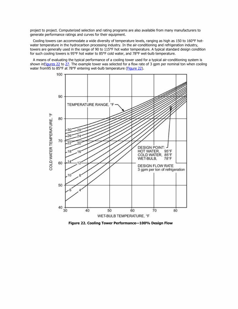
A means of evaluating the typical performance of a cooling tower used for a typical air-conditioning system is shown inFigures 22 to 27. The example tower was selected for a flow rate of 3 gpm per nominal ton when cooling water from95 to 85°F at 78°F entering wet-bulb temperature (Figure 22).
Figure 22. Cooling Tower Performance—100% Design Flow
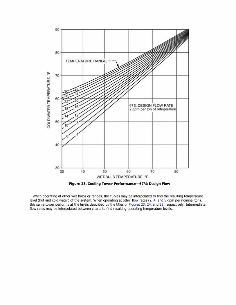
Figure 23. Cooling Tower Performance—67% Design Flow
When operating at other wet bulbs or ranges, the curves may be interpolated to find the resulting temperature level (hot and cold water) of the system. When operating at other flow rates (2, 4, and 5 gpm per nominal ton), this same tower performs at the levels described by the titles of Figures 23, 24, and 25, respectively. Intermediate flow rates may be interpolated between charts to find resulting operating temperature levels.
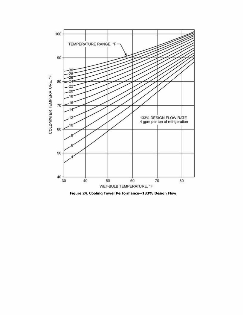
Figure 24. Cooling Tower Performance—133% Design Flow
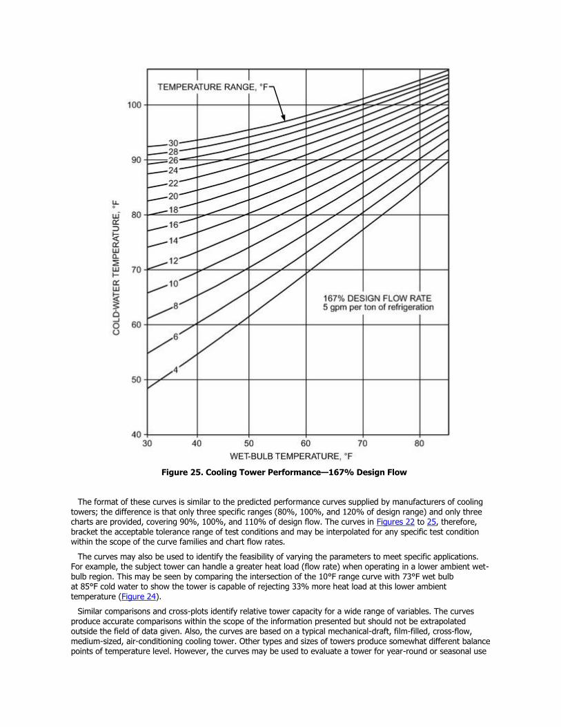
Figure 25. Cooling Tower Performance—167% Design Flow
The format of these curves is similar to the predicted performance curves supplied by manufacturers of cooling towers; the difference is that only three specific ranges (80%, 100%, and 120% of design range) and only three charts are provided, covering 90%, 100%, and 110% of design flow. The curves in Figures 22 to 25, therefore, bracket the acceptable tolerance range of test conditions and may be interpolated for any specific test condition within the scope of the curve families and chart flow rates.
The curves may also be used to identify the feasibility of varying the parameters to meet specific applications. For example, the subject tower can handle a greater heat load (flow rate) when operating in a lower ambient wet-bulb region. This may be seen by comparing the intersection of the 10°F range curve with 73°F wet bulb at 85°F cold water to show the tower is capable of rejecting 33% more heat load at this lower ambient temperature (Figure 24).
Similar comparisons and cross-plots identify relative tower capacity for a wide range of variables. The curves produce accurate comparisons within the scope of the information presented but should not be extrapolated outside the field of data given. Also, the curves are based on a typical mechanical-draft, film-filled, cross-flow, medium-sized, air-conditioning cooling tower. Other types and sizes of towers produce somewhat different balance points of temperature level. However, the curves may be used to evaluate a tower for year-round or seasonal use
if they are restricted to the general operating characteristics described. (See specific manufacturer’s data for
maximum accuracy when planning for test or critical temperature needs.)
A cooling tower selected for a specified design condition will operate at other temperature levels when the ambient temperature is off-design or when heat load or flow rate varies from the design condition. When flow rate is held constant, range falls as heat load falls, causing temperature levels to fall to a closer approach. Hot- and cold-water temperatures fall when the ambient wet bulb falls at constant heat load, range, and flow rate. As water loading to a particular tower falls at constant ambient wet bulb and range, the tower cools the water to a lower temperature level or closer approach to the wet bulb.
COOLING TOWER THERMAL PERFORMANCE
Three basic alternatives are available to a purchaser/designer seeking assurance that a cooling tower will perform as specified: (1) certification of performance by an independent third party such as the Cooling Technology Institute (CTI), (2) an acceptance test performed at the site after the unit is installed, or (3) a performance bond. Codes and standards that pertain to performance certification and field testing of cooling towers are listed in Chapter 51.
Certification. The thermal performance of many commercially available cooling tower lines, both open- and closed-circuit, is certified by CTI in accordance with their Standard STD-201, which applies to mechanical-draft, open- and closed-circuit water cooling towers. It is based on entering wet-bulb temperature and certifies tower performance when operating in an open, unrestricted environment. Independent performance certification eliminates the need for field acceptance tests and performance bonds.
Field Acceptance Test. As an alternative to certification, tower performance can be verified after installation by conducting a field acceptance test in accordance with one of the two available test standards. Of the two standards, CTI Standard ATC-105 is more commonly used, although American Society of Mechanical Engineers (ASME) StandardPTC-23 is also used. These standards are similar in their requirements, and both base the performance evaluation on entering wet-bulb temperature. ASME Standard PTC-23, however, provides an alternative for evaluation based on ambient wet-bulb temperature as well.
With either procedure, the test consists of measuring the hot-water temperature in the inlet piping to the tower or in the hot-water distribution basin. Preferably, the cold-water temperature is measured at the discharge of the circulating pump, where there is much less chance for temperature stratification. The wet-bulb temperature is measured by an array of mechanically aspirated psychrometers. The recirculating water flow rate is measured by any of several approved methods, usually a pitot-tube traverse of the piping leading to the tower. Recently calibrated instruments should be used for all measurements, and electronic data acquisition is recommended for all but the smallest installations.
For an accurate test, the tower should be running under a steady heat load combined with a steady flow of recirculating water, both as near design as possible. Weather conditions should be reasonably stable, with prevailing winds of 10 mph or less. The tower should be clean and adjusted for proper water distribution, with all fans operating at design speed. Both the CTI and ASME standards specify maximum recommended deviations from design operating conditions of range, flow, wet-bulb temperature, heat load, and fan power.
Performance Bond. A few manufacturers offer a performance bond, which provides for seeking redress from a surety in the event the cooling tower does not meet the manufacturer’s rated thermal performance.
COOLING TOWER THEORY
Baker and Shryock (1961) developed the following theory. Consider a cooling tower having one square foot of plan area; cooling volume V, containing extended water surface per unit volume a; and water mass flow rate L and air mass flow rate G. Figure 26 schematically shows the processes of mass and energy transfer. The bulk water at temperature tis surrounded by the bulk air at dry-bulb temperature ta, having enthalpy ha and humidity ratio Wa. The interface is assumed to be a film of saturated air with an intermediate temperature t″, enthalpy h″, and humidity ratio W″. Assuming a constant value of 1 Btu/lb ·°F for the specific heat of water cp, the total energy transfer from the water to the interface is
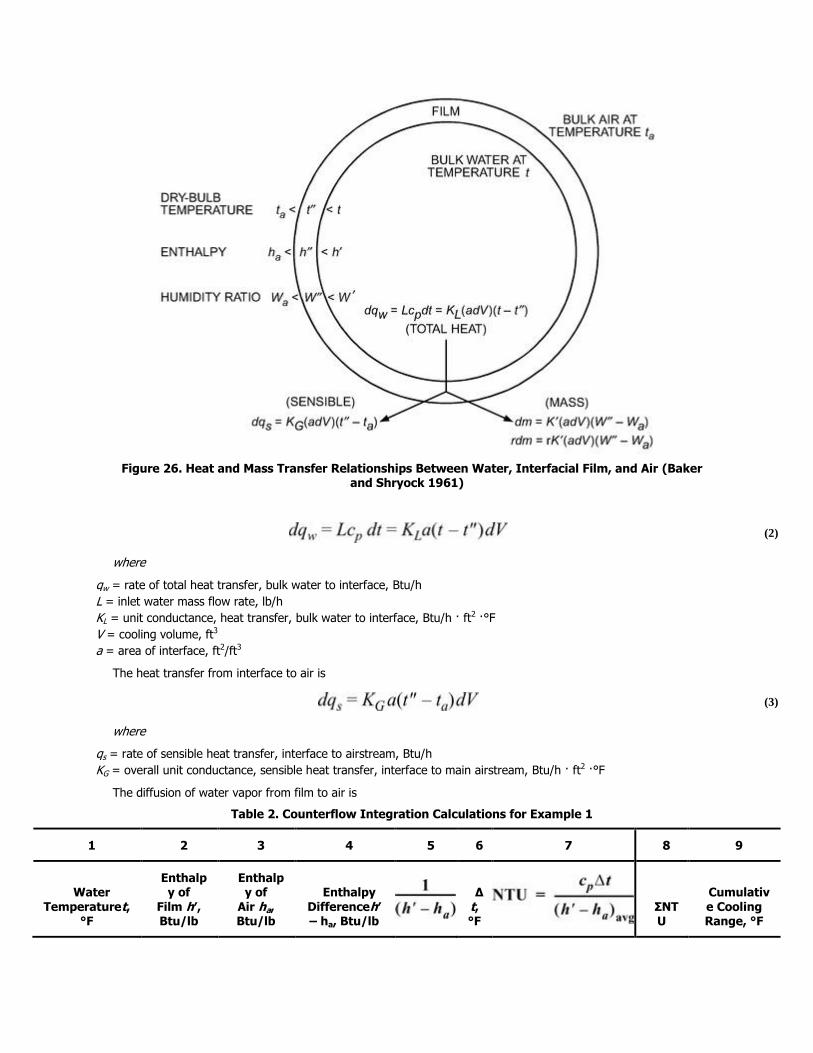
Figure 26. Heat and Mass Transfer Relationships Between Water, Interfacial Film, and Air (Baker and Shryock 1961)
(2)
where
qw = rate of total heat transfer, bulk water to interface, Btu/h
L = inlet water mass flow rate, lb/h
KL = unit conductance, heat transfer, bulk water to interface, Btu/h · ft2 ·°F
V = cooling volume, ft3
a = area of interface, ft2/ft3
The heat transfer from interface to air is
(3)
where
qs = rate of sensible heat transfer, interface to airstream, Btu/h
KG = overall unit conductance, sensible heat transfer, interface to main airstream, Btu/h · ft2 ·°F
The diffusion of water vapor from film to air is
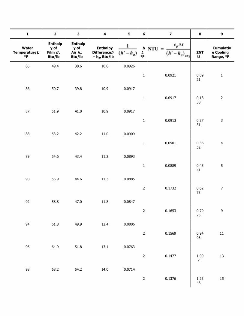
Table 2. Counterflow Integration Calculations for Example 1
1 2 3 4 5 6 7 8 9
Water Temperaturet,
°F
Enthalpy of
Film h′, Btu/lb
Enthalpy of
Air ha, Btu/lb
Enthalpy Differenceh′ – ha, Btu/lb
Δt, °F
ΣNTU
Cumulative Cooling Range, °F
1 2 3 4 5 6 7 8 9
Water Temperaturet,
°F
Enthalpy of
Film h′, Btu/lb
Enthalpy of
Air ha, Btu/lb
Enthalpy Differenceh′ – ha, Btu/lb
Δt, °F
ΣNTU
Cumulative Cooling Range, °F
85 49.4 38.6 10.8 0.0926
1 0.0921 0.09
21 1
86 50.7 39.8 10.9 0.0917
1 0.0917 0.18
38 2
87 51.9 41.0 10.9 0.0917
1 0.0913 0.27
51 3
88 53.2 42.2 11.0 0.0909
1 0.0901 0.36
52 4
89 54.6 43.4 11.2 0.0893
1 0.0889 0.45
41 5
90 55.9 44.6 11.3 0.0885
2 0.1732 0.62
73 7
92 58.8 47.0 11.8 0.0847
2 0.1653 0.79
25 9
94 61.8 49.9 12.4 0.0806
2 0.1569 0.94
93 11
96 64.9 51.8 13.1 0.0763
2 0.1477 1.09
7 13
98 68.2 54.2 14.0 0.0714
2 0.1376 1.23
46 15
1 2 3 4 5 6 7 8 9
Water Temperaturet,
°F
Enthalpy of
Film h′, Btu/lb
Enthalpy of
Air ha, Btu/lb
Enthalpy Differenceh′ – ha, Btu/lb
Δt, °F
ΣNTU
Cumulative Cooling Range, °F
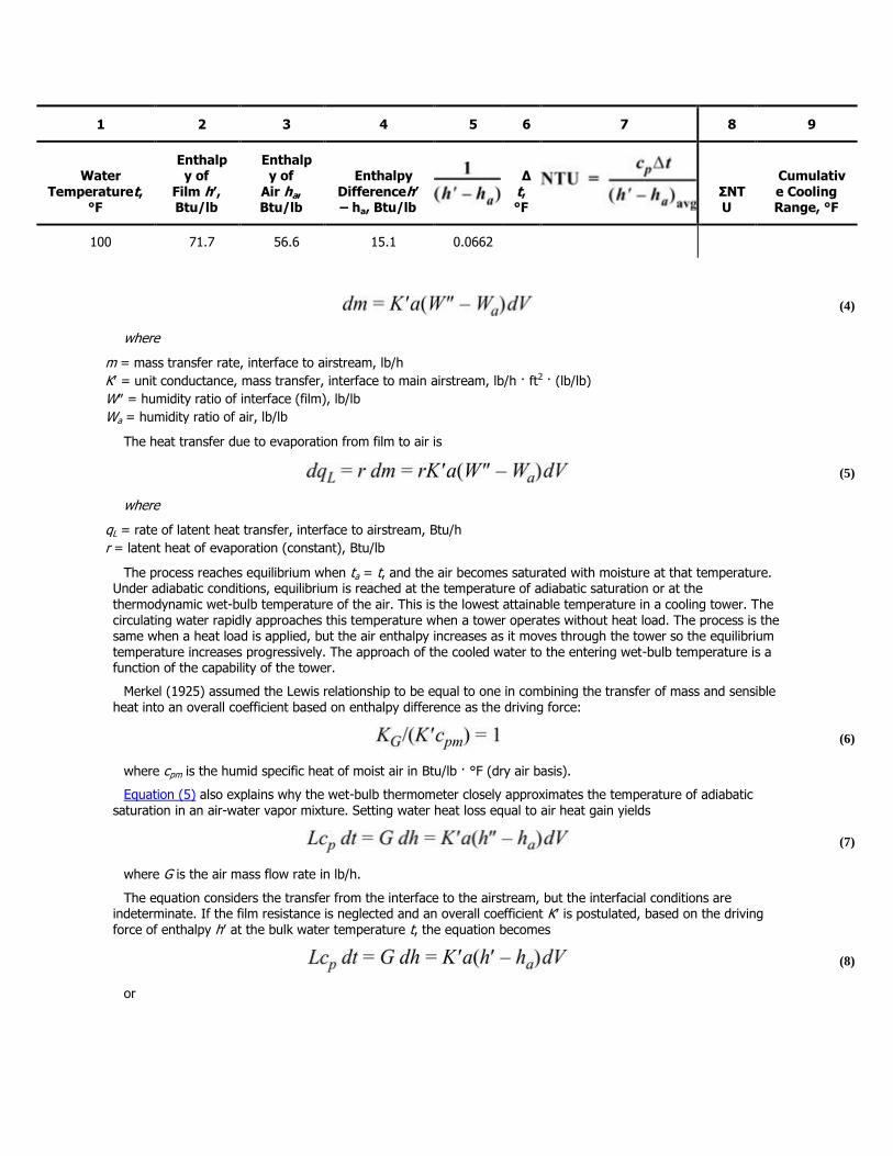
100 71.7 56.6 15.1 0.0662
(4)
where
m = mass transfer rate, interface to airstream, lb/h
K′ = unit conductance, mass transfer, interface to main airstream, lb/h · ft2 · (lb/lb)
W″ = humidity ratio of interface (film), lb/lb
Wa = humidity ratio of air, lb/lb
The heat transfer due to evaporation from film to air is
(5)
where
qL = rate of latent heat transfer, interface to airstream, Btu/h
r = latent heat of evaporation (constant), Btu/lb
The process reaches equilibrium when ta = t, and the air becomes saturated with moisture at that temperature. Under adiabatic conditions, equilibrium is reached at the temperature of adiabatic saturation or at the thermodynamic wet-bulb temperature of the air. This is the lowest attainable temperature in a cooling tower. The circulating water rapidly approaches this temperature when a tower operates without heat load. The process is the same when a heat load is applied, but the air enthalpy increases as it moves through the tower so the equilibrium temperature increases progressively. The approach of the cooled water to the entering wet-bulb temperature is a function of the capability of the tower.
Merkel (1925) assumed the Lewis relationship to be equal to one in combining the transfer of mass and sensible heat into an overall coefficient based on enthalpy difference as the driving force:
(6)
where cpm is the humid specific heat of moist air in Btu/lb · °F (dry air basis).
Equation (5) also explains why the wet-bulb thermometer closely approximates the temperature of adiabatic saturation in an air-water vapor mixture. Setting water heat loss equal to air heat gain yields
(7)
where G is the air mass flow rate in lb/h.
The equation considers the transfer from the interface to the airstream, but the interfacial conditions are indeterminate. If the film resistance is neglected and an overall coefficient K′ is postulated, based on the driving force of enthalpy h′ at the bulk water temperature t, the equation becomes
(8)
or
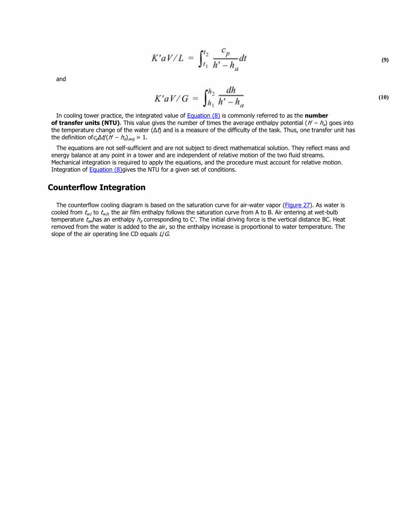
(9)
and
(10)
In cooling tower practice, the integrated value of Equation (8) is commonly referred to as the number of transfer units (NTU). This value gives the number of times the average enthalpy potential (h′ – ha) goes into the temperature change of the water (Δt) and is a measure of the difficulty of the task. Thus, one transfer unit has the definition ofcpΔt/(h′ – ha)avg = 1.
The equations are not self-sufficient and are not subject to direct mathematical solution. They reflect mass and energy balance at any point in a tower and are independent of relative motion of the two fluid streams. Mechanical integration is required to apply the equations, and the procedure must account for relative motion. Integration of Equation (8)gives the NTU for a given set of conditions.
Counterflow Integration
The counterflow cooling diagram is based on the saturation curve for air-water vapor (Figure 27). As water is cooled from tw1 to tw2, the air film enthalpy follows the saturation curve from A to B. Air entering at wet-bulb temperature tawhas an enthalpy ha corresponding to C′. The initial driving force is the vertical distance BC. Heat removed from the water is added to the air, so the enthalpy increase is proportional to water temperature. The slope of the air operating line CD equals L/G.
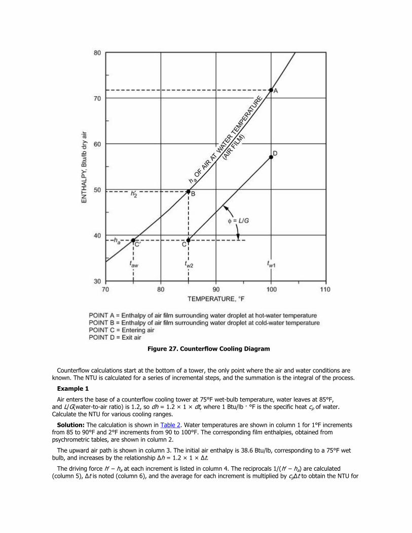
Figure 27. Counterflow Cooling Diagram
Counterflow calculations start at the bottom of a tower, the only point where the air and water conditions are known. The NTU is calculated for a series of incremental steps, and the summation is the integral of the process.
Example 1
Air enters the base of a counterflow cooling tower at 75°F wet-bulb temperature, water leaves at 85°F, and L/G(water-to-air ratio) is 1.2, so dh = 1.2 × 1 × dt, where 1 Btu/lb · °F is the specific heat cp of water. Calculate the NTU for various cooling ranges.
Solution: The calculation is shown in Table 2. Water temperatures are shown in column 1 for 1°F increments from 85 to 90°F and 2°F increments from 90 to 100°F. The corresponding film enthalpies, obtained from psychrometric tables, are shown in column 2.
The upward air path is shown in column 3. The initial air enthalpy is 38.6 Btu/lb, corresponding to a 75°F wet bulb, and increases by the relationship Δh = 1.2 × 1 × Δt.
The driving force h′ – ha at each increment is listed in column 4. The reciprocals 1/(h′ – ha) are calculated (column 5), Δt is noted (column 6), and the average for each increment is multiplied by cpΔt to obtain the NTU for
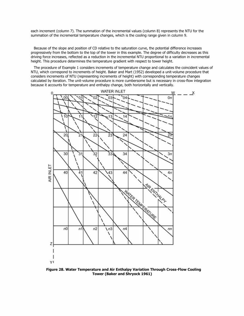
each increment (column 7). The summation of the incremental values (column 8) represents the NTU for the
summation of the incremental temperature changes, which is the cooling range given in column 9.
Because of the slope and position of CD relative to the saturation curve, the potential difference increases progressively from the bottom to the top of the tower in this example. The degree of difficulty decreases as this driving force increases, reflected as a reduction in the incremental NTU proportional to a variation in incremental height. This procedure determines the temperature gradient with respect to tower height.
The procedure of Example 1 considers increments of temperature change and calculates the coincident values of NTU, which correspond to increments of height. Baker and Mart (1952) developed a unit-volume procedure that considers increments of NTU (representing increments of height) with corresponding temperature changes calculated by iteration. The unit-volume procedure is more cumbersome but is necessary in cross-flow integration because it accounts for temperature and enthalpy change, both horizontally and vertically.
Figure 28. Water Temperature and Air Enthalpy Variation Through Cross-Flow Cooling Tower (Baker and Shryock 1961)
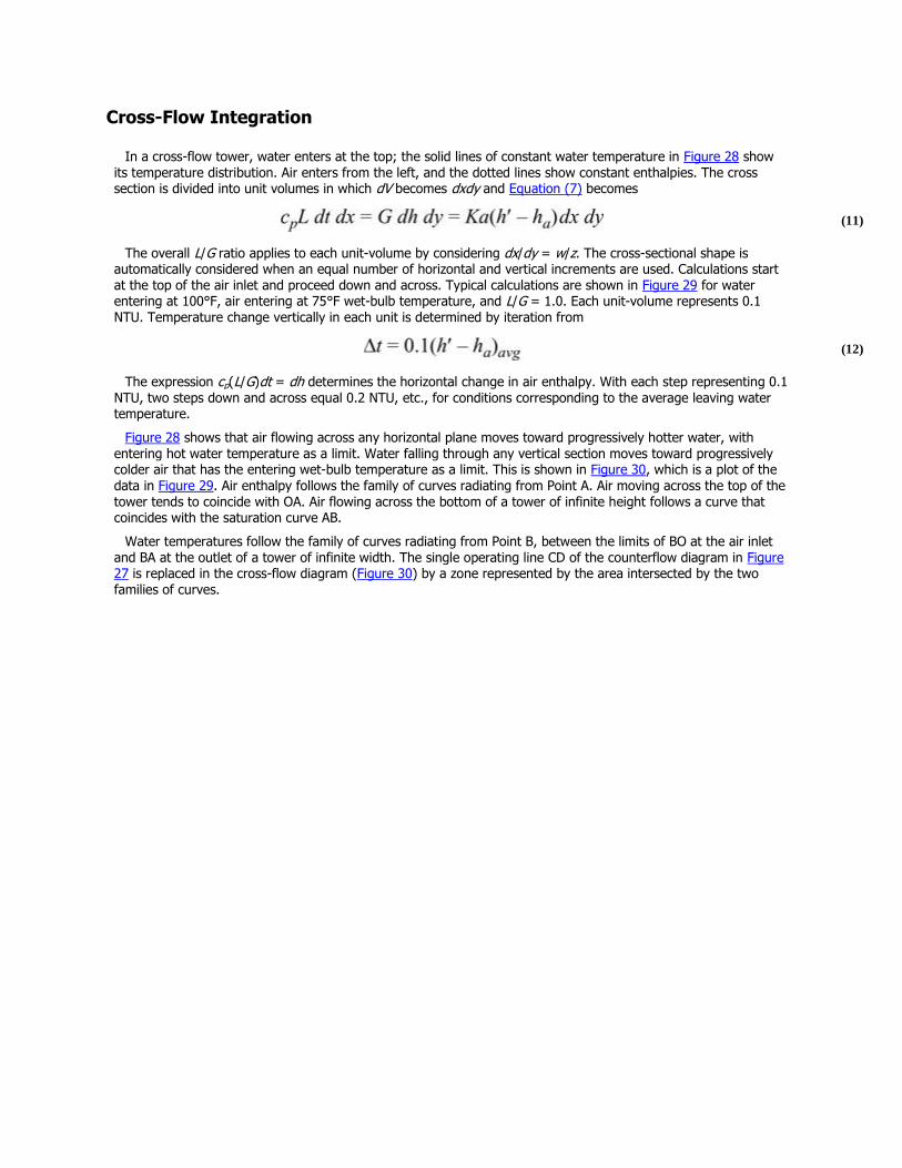
Cross-Flow Integration
In a cross-flow tower, water enters at the top; the solid lines of constant water temperature in Figure 28 show its temperature distribution. Air enters from the left, and the dotted lines show constant enthalpies. The cross section is divided into unit volumes in which dV becomes dxdy and Equation (7) becomes
(11)
The overall L/G ratio applies to each unit-volume by considering dx/dy = w/z. The cross-sectional shape is automatically considered when an equal number of horizontal and vertical increments are used. Calculations start at the top of the air inlet and proceed down and across. Typical calculations are shown in Figure 29 for water entering at 100°F, air entering at 75°F wet-bulb temperature, and L/G = 1.0. Each unit-volume represents 0.1 NTU. Temperature change vertically in each unit is determined by iteration from
(12)
The expression cp(L/G)dt = dh determines the horizontal change in air enthalpy. With each step representing 0.1 NTU, two steps down and across equal 0.2 NTU, etc., for conditions corresponding to the average leaving water temperature.
Figure 28 shows that air flowing across any horizontal plane moves toward progressively hotter water, with entering hot water temperature as a limit. Water falling through any vertical section moves toward progressively colder air that has the entering wet-bulb temperature as a limit. This is shown in Figure 30, which is a plot of the data in Figure 29. Air enthalpy follows the family of curves radiating from Point A. Air moving across the top of the tower tends to coincide with OA. Air flowing across the bottom of a tower of infinite height follows a curve that coincides with the saturation curve AB.
Water temperatures follow the family of curves radiating from Point B, between the limits of BO at the air inlet and BA at the outlet of a tower of infinite width. The single operating line CD of the counterflow diagram in Figure 27 is replaced in the cross-flow diagram (Figure 30) by a zone represented by the area intersected by the two families of curves.
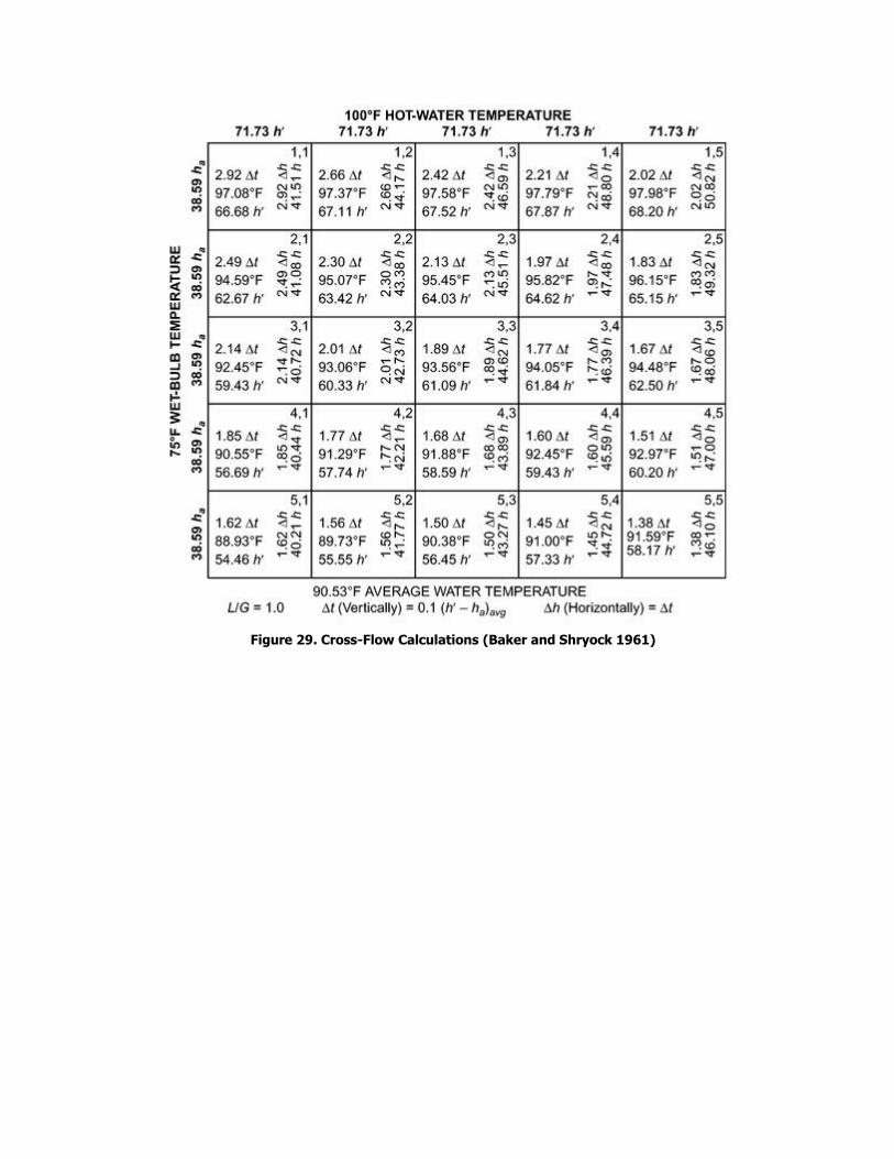
Figure 29. Cross-Flow Calculations (Baker and Shryock 1961)
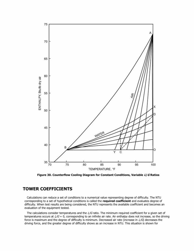
Figure 30. Counterflow Cooling Diagram for Constant Conditions, Variable L/G Ratios
TOWER COEFFICIENTS
Calculations can reduce a set of conditions to a numerical value representing degree of difficulty. The NTU corresponding to a set of hypothetical conditions is called the required coefficient and evaluates degree of difficulty. When test results are being considered, the NTU represents the available coefficient and becomes an evaluation of the equipment tested.
The calculations consider temperatures and the L/G ratio. The minimum required coefficient for a given set of temperatures occurs at L/G = 0, corresponding to an infinite air rate. Air enthalpy does not increase, so the driving force is maximum and the degree of difficulty is minimum. Decreased air rate (increase in L/G) decreases the driving force, and the greater degree of difficulty shows as an increase in NTU. This situation is shown for
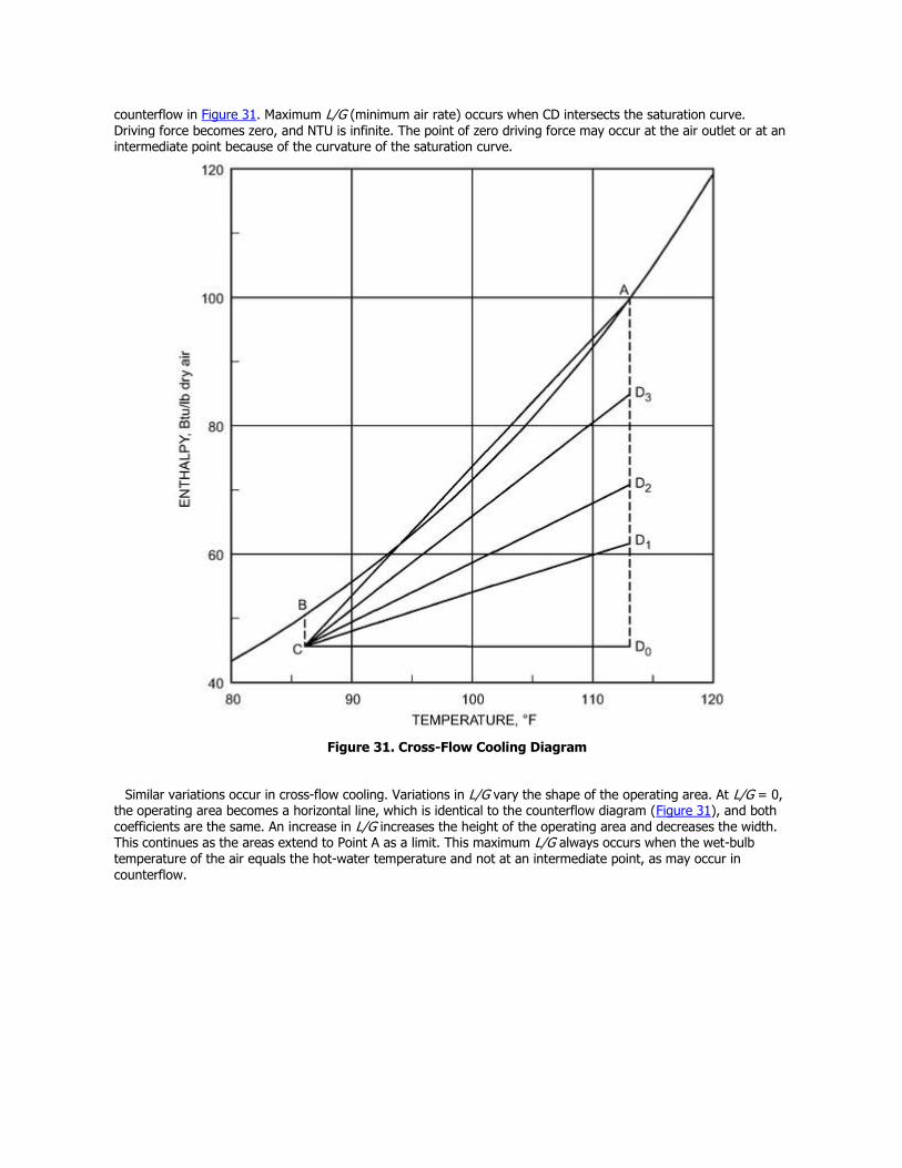
counterflow in Figure 31. Maximum L/G (minimum air rate) occurs when CD intersects the saturation curve.
Driving force becomes zero, and NTU is infinite. The point of zero driving force may occur at the air outlet or at an intermediate point because of the curvature of the saturation curve.
Figure 31. Cross-Flow Cooling Diagram
Similar variations occur in cross-flow cooling. Variations in L/G vary the shape of the operating area. At L/G = 0, the operating area becomes a horizontal line, which is identical to the counterflow diagram (Figure 31), and both coefficients are the same. An increase in L/G increases the height of the operating area and decreases the width. This continues as the areas extend to Point A as a limit. This maximum L/G always occurs when the wet-bulb temperature of the air equals the hot-water temperature and not at an intermediate point, as may occur in counterflow.
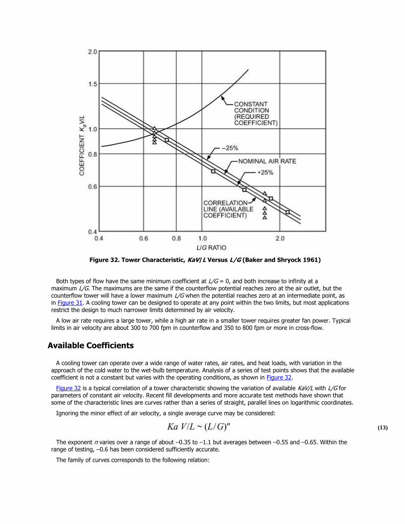
Figure 32. Tower Characteristic, KaV/L Versus L/G (Baker and Shryock 1961)
Both types of flow have the same minimum coefficient at L/G = 0, and both increase to infinity at a maximum L/G. The maximums are the same if the counterflow potential reaches zero at the air outlet, but the counterflow tower will have a lower maximum L/G when the potential reaches zero at an intermediate point, as in Figure 31. A cooling tower can be designed to operate at any point within the two limits, but most applications restrict the design to much narrower limits determined by air velocity.
A low air rate requires a large tower, while a high air rate in a smaller tower requires greater fan power. Typical limits in air velocity are about 300 to 700 fpm in counterflow and 350 to 800 fpm or more in cross-flow.
Available Coefficients
A cooling tower can operate over a wide range of water rates, air rates, and heat loads, with variation in the approach of the cold water to the wet-bulb temperature. Analysis of a series of test points shows that the available coefficient is not a constant but varies with the operating conditions, as shown in Figure 32.
Figure 32 is a typical correlation of a tower characteristic showing the variation of available KaV/L with L/G for parameters of constant air velocity. Recent fill developments and more accurate test methods have shown that
some of the characteristic lines are curves rather than a series of straight, parallel lines on logarithmic coordinates.
Ignoring the minor effect of air velocity, a single average curve may be considered:
(13)
The exponent n varies over a range of about –0.35 to –1.1 but averages between –0.55 and –0.65. Within the range of testing, –0.6 has been considered sufficiently accurate.
The family of curves corresponds to the following relation:
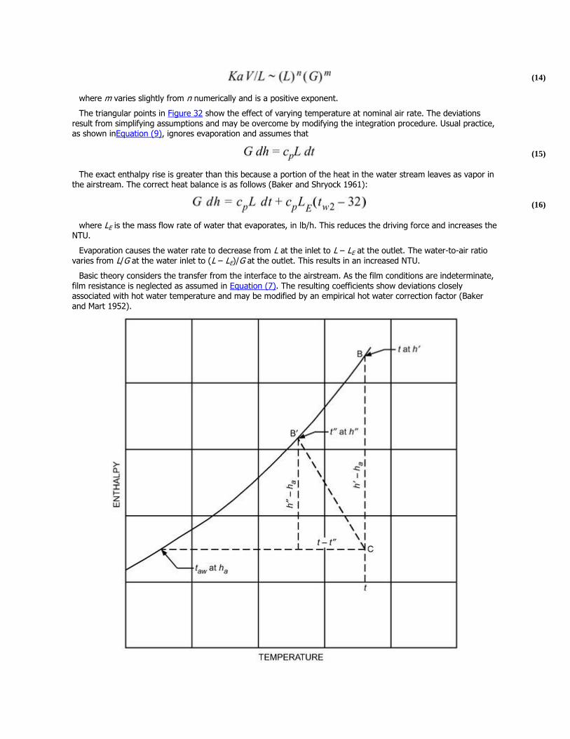
(14)
where m varies slightly from n numerically and is a positive exponent.
The triangular points in Figure 32 show the effect of varying temperature at nominal air rate. The deviations result from simplifying assumptions and may be overcome by modifying the integration procedure. Usual practice, as shown inEquation (9), ignores evaporation and assumes that
(15)
The exact enthalpy rise is greater than this because a portion of the heat in the water stream leaves as vapor in the airstream. The correct heat balance is as follows (Baker and Shryock 1961):
(16)
where LE is the mass flow rate of water that evaporates, in lb/h. This reduces the driving force and increases the NTU.
Evaporation causes the water rate to decrease from L at the inlet to L – LE at the outlet. The water-to-air ratio varies from L/G at the water inlet to (L – LE)/G at the outlet. This results in an increased NTU.
Basic theory considers the transfer from the interface to the airstream. As the film conditions are indeterminate, film resistance is neglected as assumed in Equation (7). The resulting coefficients show deviations closely associated with hot water temperature and may be modified by an empirical hot water correction factor (Baker and Mart 1952).
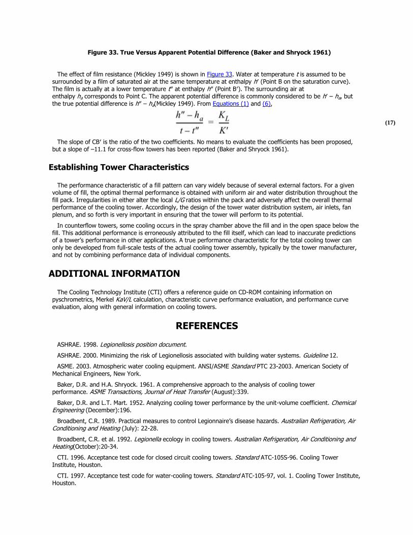
Figure 33. True Versus Apparent Potential Difference (Baker and Shryock 1961)
The effect of film resistance (Mickley 1949) is shown in Figure 33. Water at temperature t is assumed to be surrounded by a film of saturated air at the same temperature at enthalpy h′ (Point B on the saturation curve). The film is actually at a lower temperature t″ at enthalpy h″ (Point B′). The surrounding air at enthalpy ha corresponds to Point C. The apparent potential difference is commonly considered to be h′ – ha, but the true potential difference is h″ – ha(Mickley 1949). From Equations (1) and (6),
(17)
The slope of CB′ is the ratio of the two coefficients. No means to evaluate the coefficients has been proposed, but a slope of –11.1 for cross-flow towers has been reported (Baker and Shryock 1961).
Establishing Tower Characteristics
The performance characteristic of a fill pattern can vary widely because of several external factors. For a given volume of fill, the optimal thermal performance is obtained with uniform air and water distribution throughout the fill pack. Irregularities in either alter the local L/G ratios within the pack and adversely affect the overall thermal performance of the cooling tower. Accordingly, the design of the tower water distribution system, air inlets, fan plenum, and so forth is very important in ensuring that the tower will perform to its potential.
In counterflow towers, some cooling occurs in the spray chamber above the fill and in the open space below the fill. This additional performance is erroneously attributed to the fill itself, which can lead to inaccurate predictions of a tower’s performance in other applications. A true performance characteristic for the total cooling tower can only be developed from full-scale tests of the actual cooling tower assembly, typically by the tower manufacturer, and not by combining performance data of individual components.
ADDITIONAL INFORMATION
The Cooling Technology Institute (CTI) offers a reference guide on CD-ROM containing information on pyschrometrics, Merkel KaV/L calculation, characteristic curve performance evaluation, and performance curve evaluation, along with general information on cooling towers.
REFERENCES
ASHRAE. 1998. Legionellosis position document.
ASHRAE. 2000. Minimizing the risk of Legionellosis associated with building water systems. Guideline 12.
ASME. 2003. Atmospheric water cooling equipment. ANSI/ASME Standard PTC 23-2003. American Society of Mechanical Engineers, New York.
Baker, D.R. and H.A. Shryock. 1961. A comprehensive approach to the analysis of cooling tower performance. ASME Transactions, Journal of Heat Transfer (August):339.
Baker, D.R. and L.T. Mart. 1952. Analyzing cooling tower performance by the unit-volume coefficient. Chemical Engineering (December):196.
Broadbent, C.R. 1989. Practical measures to control Legionnaire’s disease hazards. Australian Refrigeration, Air Conditioning and Heating (July): 22-28.
Broadbent, C.R. et al. 1992. Legionella ecology in cooling towers. Australian Refrigeration, Air Conditioning and Heating(October):20-34.
CTI. 1996. Acceptance test code for closed circuit cooling towers. Standard ATC-105S-96. Cooling Tower Institute, Houston.
CTI. 1997. Acceptance test code for water-cooling towers. Standard ATC-105-97, vol. 1. Cooling Tower Institute, Houston.
CTI. 1996. Standard for the certification of water-cooling tower thermal performance. Standard STD-201-96.
Cooling Tower Institute, Houston.
Hensley, J.C., ed. 1985. Cooling tower fundamentals, 2nd ed. Marley Cooling Tower Company, Kansas City.
McCann, M. 1988. Cooling towers take the heat. Engineered Systems 5(October):58-61.
Meitz, A. 1986. Clean cooling systems minimize Legionella exposure. Heating, Piping and Air Conditioning 58(August):99-102.
Merkel, F. 1925. Verduftungskühlung. Forschungarbeiten 275.
Mickley, H.S. 1949. Design of forced-draft air conditioning equipment. Chemical Engineering Progress 45:739.
Rosa, F. 1992. Some contributing factors in indoor air quality problems. National Engineer (May):14.
BIBLIOGRAPHY
Baker, D.R. 1962. Use charts to evaluate cooling towers. Petroleum Refiner (November).
Braun, J.E. and Diderrich, G.T. 1990. Near-optimal control of cooling towers for chilled water systems. ASHRAE Transactions 96(2):806-813.
CIBSE. 1991. Minimizing the risk of Legionnaire’s disease. Technical Memorandum TM13. The Chartered Institute of Building Services Engineers, London.
CTI. 2003. CTI ToolKit, v. 3.0. Cooling Technology Institute, Houston.
Fliermans, C.B. et al. 1981. Measure of Legionella pneumophila activity in situ. Current Microbiology 6:89-94.
Fluor Products Company. 1958. Evaluated weather data for cooling equipment design.
Kohloss, F.H. 1970. Cooling tower application. ASHRAE Journal (August).
Landon, R.D. and J.R. Houx, Jr. 1973. Plume abatement and water conservation with the wet-dry cooling tower. Marley Cooling Tower Company, Mission, Kansas City.
Mallison, G.F. 1980. Legionellosis: Environmental aspects. Annals of the New York Academy of Science 353:67-70.
McBurney, K. 1990. Maintenance suggestions for cooling towers and accessories. ASHRAE Journal 32(6):16-26.
Meitz, A. 1988. Microbial life in cooling water systems. ASHRAE Journal 30(August):25-30.
White, T.L. 1994. Winter cooling tower operation for a central chilled water system. ASHRAE Transactions 100(1):811-816.


![Natural Gas Engine-Driven Chillers Water-Cooled STx / … Cooling Tower Flow [GPM] - Flow To Condenser Only [GPM] - 40Flow To Dump HX Only ... data acquisition and system control by](https://img.pdfslide.net/doc/110x75/5aaff1e67f8b9a59478df696/natural-gas-engine-driven-chillers-water-cooled-stx-cooling-tower-flow-gpm.jpg)


![Georgetown University New Science Center · 2010. 12. 10. · Preheat HW Coil Cooling Coil Enthalpy Wheel EWT [°F] GPM EWT GPM Effectiveness Sens. Effectiveness Latent AHU‐1 80](https://img.pdfslide.net/doc/110x75/60fd65782914721a882d2fd4/georgetown-university-new-science-2010-12-10-preheat-hw-coil-cooling-coil-enthalpy.jpg)


![[GPM 083] Mi-14[1].GPM](https://img.pdfslide.net/doc/110x75/577d20571a28ab4e1e9298ca/gpm-083-mi-141gpm.jpg)

![[GPM 032] - F-18 Hornet](https://img.pdfslide.net/doc/110x75/55cfe3d45503467d968b6603/gpm-032-f-18-hornet.jpg)