Embed Size (px)
Citation preview
Chapter 4-1 – Automation
2013
This latest edition incorporates all rule changes. The latest revisions are shown with a vertical line. The section title is framed if the section is revised completely. Changes after the publication of the rule are written in red colour. Unless otherwise specified, these Rules apply to ships for which the date of contract for construction as defined in IACS PR No.29 is on or after 2nd of September 2013. New rules or amendments entering into force after the date of contract for construction are to be applied if required by those rules. See Rule Change Notices on TL website for details. "General Terms and Conditions" of the respective latest edition will be applicable (see Rules for Classification and Surveys). If there is a difference between the rules in English and in Turkish, the rule in English is to be considered as valid. This publication is available in print and electronic pdf version. Once downloaded, this document will become UNCONTROLLED. Please check www.turkloydu.org for the amended and valid version. All rights are reserved by Türk Loydu, and content may not be reproduced, disseminated, published, or transferred in any form or by any means, except with the prior written permission of TL.
TÜRK LOYDU
Head Office Postane Mah. Tersaneler Cad. No:26 Tuzla 34944 İSTANBUL / TÜRKİYE
Tel : (90-216) 581 37 00
Fax : (90-216) 581 38 00
E-mail : [email protected]
http://www.turkloydu.org
Regional Offices
Ankara Eskişehir Yolu Mustafa Kemal Mah. 2159. Sokak No : 6/4 Çankaya - ANKARA / TÜRKİYE
Tel : (90-312) 219 56 34 - 219 68 25
Fax : (90-312) 219 69 72
E-mail : [email protected]
İzmir Atatürk Cad. No :378 K.4 D.402 Kavalalılar Apt. 35220 Alsancak - İZMİR / TÜRKİYE
Tel : (90-232) 464 29 88
Fax : (90-232) 464 87 51
E-mail : [email protected]
Adana Çınarlı Mah. Atatürk Cad. Aziz Naci İş Merkezi No:5 K.1 D.2 Seyhan - ADANA / TÜRKİYE
Tel : (90- 322) 363 30 12
Fax : (90- 322) 363 30 19
E-mail : [email protected] Marmaris Atatürk Cad. 99 Sok. No:1 Ketenbaş Apt. Kat:4 Daire 6 Marmaris - MUĞLA / TÜRKİYE
Tel : (90- 252) 412 46 55
Fax : (90- 252) 412 46 54
E-mail : [email protected]
Contents
Rules for Classification of Steel Ships – Automation
Section 1- General Rules and Instructions Page
A. General ...................................................................................................................... ......................... 1-2
B. Class Notations...................................................................................................................... ................ 1-2
C. Definitions ............................................................................................................................................. 1-3
D. Documents for Submission ................................................................................................................... 1-3
E. Ship Documents .................................................................................................................................... 1-3
F. Maintenance .......................................................................................................................................... 1-4
G. Spare Parts ........................................................................................................................................... 1-4
Section 2- Range of Control and Monitoring Equipment
A. Machinery With Class Notation Aut ................................................................................................ 2-2
B. MACHINERY WITH CLASS NOTATION AUT-nh ............................................................................ 2-3
C. Machinery With Class Notation Aut-C ............................................................................................. 2-3
Section 3- Basic Requirements
A. Design and Performance ............................................................................................................. 3-2
B. Computer Systems ........................................................................................................................ 3-3
C. Input and Output Units ................................................................................................................... 3-3
D. Open / Closed Loop Control Equipment .......................................................................................... 3-3
E. Integration of Systems for Essential Equipment ............................................................................... 3-4
Section 4- Automation Systems
A. Machinery Alarm Systems ............................................................................................................. 4-2
B. Duty Alarm Systems ...................................................................................................................... 4-3
C. Safety Systems ............................................................................................................................. 4-4
D. Reductions ................................................................................................................................... 4-4
E. Safety Devices .............................................................................................................................. 4-4
F. Communication Systems ....................................................................................................................... 4-5
G. Fire Detection Systems For Machinery Spaces .................................................................................... 4-5
H. Stand-By Circuits / Automatic Controls ................................................................................................. 4-5
Contents
Section 5- Main Propulsion Plant
A. Remote Controls ................................................................................................................................... 5-2
B. Diesel Engines ...................................................................................................................................... 5-3
C. Main Steam Plants ................................................................................................................................ 5-4
D. Gas Turbine Systems ............................................................................................................................ 5-4
E. Electrical Propulsion Plants ................................................................................................................... 5-5
F. Multi-Shaft Systems, Systems With Several Propulsion Machines ....................................................... 5-5
Section 6- Auxiliary Machinery Systems
A. General ................................................................................................................................................. 6-2
B. Auxiliary Diesel Engines ........................................................................................................................ 6-2
C. Auxiliary Turbines .................................................................................................................................. 6-2
D. Auxiliary Steam Plants .......................................................................................................................... 6-2
E. Thermal Oil Systems ............................................................................................................................. 6-2
F. Purifier Systems .................................................................................................................................... 6-2
G. Air Compressor ..................................................................................................................................... 6-2
H. Bilge and Drain Facilities ....................................................................................................................... 6-3
I. Valves on The Shell Plating .................................................................................................................. 6-3
Section 7- Tests
A. General ................................................................................................................................................. 7-2
B. Examination of Technical Documents ................................................................................................... 7-2
C. Tests Conducted at The Manufacturer’s Works ................................................................................... 7-2
D. Tests on Board ...................................................................................................................................... 7-2
E. Type Tests ............................................................................................................................................ 7-4
Section 8- Tables
A. General ................................................................................................................................................. 8-2
B. Sensors for Main Propulsion Diesel Engines ........................................................................................ 8-3
C. Sensors for Main Steam Plant ............................................................................................................... 8-7
D. Sensors for Propulsion Gas Turbines ................................................................................................... 8-9
E. Sensors for Propulsion Plant and Steering Devices .............................................................................. 8-10
F. Sensors for Auxiliary Diesel Engines .................................................................................................... 8-12
G. Sensors for Fuel, Separator, Generation and Utilization of Heat ........................................................... 8-13
H. Sensors for Fire Alarm Systems, Electrical Plants and Others .............................................................. 8-15
I. Stand-By Circuit and Remote Control Facility for Essential Equipment ................................................ 8-17
Section 1 – General Rules and Instructions 1-1
TÜRK LOYDU - AUTOMATION - 2013
SECTION 1
GENERAL RULES AND INSTRUCTIONS Page
A. GENERAL....................................................................................................................................................... 1-2
1. Scope
2. References to Other Rules and Regulations
B. CLASS NOTATIONS..................................................................................................................................... 1-2
1. AUT
2. AUT-nh
3. AUT-C
C. DEFINITIONS.................................................................................................................................................. 1-3
1. Alarms
2. Protective Devices
3. Safety Devices
4. Safety Systems
5. Systems
D. DOCUMENTS FOR SUBMISSION…….......................................................................................................... 1-3
1. Newbuildings
2. Modifications and Additions
E. SHIP DOCUMENTS……………...................................................................................................................... 1-3
F. MAINTENANCE.............................................................................................................................................. 1-4
G. SPARE PARTS…........................................................................................................................................… 1-4
1-2 Section 1 – General Rules and Instructions A,B
TÜRK LOYDU - AUTOMATION - 2013
A. General
1. Scope
1.1 These Construction rules apply additionally to
automated machinery systems on seagoing ships,
classified by TL which have one of the class notations in
the class certificate relating to the machinery system as
listed below under B.
1.2 Approval may be given for designs which
differ from the Rules for Constructions if they have been
checked for suitability by TL and accepted as being of
equivalent design.
1.3 TL reserve the right to specify additional
requirements to the Rules for Construction where these
are related to new systems or installations or where
they are necessary due to new findings or practical
experience.
Deviations from the Rules for Construction may be
permitted in particularly justified instances.
2. References to other rules and
regulations
2.1 The following additional TL Rules for
Construction apply:
- Chapter 4 - Machinery Installations,
- Chapter 5 - Electrical Installations.
2.2 Where requirements in respect of automated
machinery systems are not covered by these Rules for
Construction, the application of other rules and
standards is to be agreed as necessary.
2.3 Allowance is made in substance in these
Rules for Construction for the provisions of the
“International Convention for the Safety of Life at Sea”
(SOLAS) where these relate to unattended machinery
spaces.
2.4 Further Rules and Regulations, named in the
Construction Rules.
2.5 If necessary, beside of the TL Rules for
Construction national regulations are to be observed
as well.
B. Class Notations
Machinery installations which comply with TL’s Rules
for Construction for automated and/or remotely
controlled systems are given the following additions to
the class notation:
1. AUT
The machinery installation has been designed to
operate in an unmanned machinery space so that no
control and maintenance operations are required for at
least 24 hours.
Equipment must comply with the conditions laid down in
Section 2, A.
2. AUT-nh
This denotes the period during which no control and
maintenance operations are necessary, whereby nh
means that the machinery installation may be left
unmanned for n hours (h).
Equipment must comply with the conditions laid down in
Section 2, B.
3. AUT-C
Applies to machinery systems on ships with a
permanently manned machinery control room for
centralized control, remote control of the propulsion
plant from the bridge or facilities for manoeuvring the
ship from the machinery control room.
Equipment must comply with the conditions laid down in
Section 2, C.
C,D,E Section 1 – General Rules and Instructions 1-3
TÜRK LOYDU - AUTOMATION - 2013
C. Definitions
1. Alarms
An alarm gives optical and acoustical warning of
abnormal operating conditions.
2. Protective Devices
Protective devices detect actual values, activate alarms
in the event of limit-value violation and prevent
machinery and equipment being endangered. They
automatically initiate curative measures or call for
appropriate ones.
3. Safety Devices
Safety devices detect critical limit-value violations and
prevent any prevent any immediate danger to persons,
ship or machinery.
4. Safety systems
Combination of several safety-devices and/or protective
devices into one functional unit.
5. Systems
Systems contain all equipment necessary for
monitoring, control and safety including the in- and
output devices. Systems cover defined functions
including behaviour under varying operation conditions,
cycles and running.
D. Documents for Submission
The following documents are to be submitted for
examination in triplicate and in good time so that they
can be approved and made available to the surveyor
at the start of manufacture or installation of the
systems.
1. Newbuildings
1.1 Questionnaire PL-M-CL006 for motor
systems.
1.2 For each of the systems listed in Section 2:
- General plan,
- Wiring diagrams,
- Power supply plan,
- Description of functional relationships,
- General arrangement,
- Functional description.
Section 3, E is to be observed additionally for integrated
automation systems.
1.3 The list of measure points is to be submitted
for the monitoring system.
1.4 Safety programmes giving details of limit
values which result in shutdown or reduction are to be
submitted for the main propulsion plant and also for
other equipment where necessary.
1.5 TL reserve the right to demand other
documents where those submitted are not adequate to
provide an evaluation of the system.
1.6 Documents are to be marked with the ship’s
name or the shipyard’s newbuilding number and the
date of issue.
2. Modifications and Additions
Major modifications which may affect the automation
systems on a ship which is under construction or at sea
are subject to approval. Documents are to be submitted
in time before conversion.
E. Ship Documents
When a vessel is commissioned or following major
modifications and additions to the automated machinery
installations, the documents listed under D which show
the final from of the system are to be provided for
onboard use.
1-4 Section 1 – General Rules and Instructions F,G
TÜRK LOYDU - AUTOMATION - 2013
F. Maintenance
1. Access must be provided to automation
systems to allow measurements and repairs to be
carried out. Facilities such as simulation circuits, test
jacks, pilot lamps etc. are to be provided to allow
functional checks to be carried out and faults to be
located.
2. The operational capability of other systems
shall not be impaired as a result of maintenance
procedures.
3. Where maintenance for equipment which is
switched on may result in the failure of components or
in the critical condition of systems, a warning sign must
be fitted to indicate the risk.
As an alternative a statement in the operator manual
can be done in order to indicate the risk.
4. Circuit boards and plug-in connections must
be protected against unintentional mixing up.
Alternatively they must be clearly marked to show
where they belong to.
G. Spare Parts
1. When specifying the amount of spare parts
for automation systems, allowance is to be made for the
manufacturer’s recommendations.
2. The amount of spare parts is to be
documented and a corresponding list is to be carried on
board.

Section 2 – Range of Control and Monitoring Equipment 2-1
TÜRK LOYDU - AUTOMATION - 2013
SECTION 2
RANGE OF CONTROL AND MONITORING EQUİPMENT
Page
A. MACHINERY WITH CLASS NOTATION AUT.............................................................................................. 2-2
B. MACHINERY WITH CLASS NOTATION AUT-nh........................................................................................ 2-3
C. MACHINERY WITH CLASS NOTATION AUT-C…………............................................................................. 2-3
2-2 Section 2 – Range of Control and Monitoring Equipment A
TÜRK LOYDU - AUTOMATION - 2013
A. Machinery with Class Notation AUT
1. The propulsion plant and the auxiliary
equipment necessary for operation is to be prepared
free of maintenance for 24 hours.
2. Service tanks are to be refilled automatically
or are to be so sized that they do not require topping up
for 24 hours. A reserve capacity of 15 % is also to be
provided.
3. A remote control system for the propulsion
plant is to be installed on the bridge in accordance with
Section 5, A.
4. A safety system for the propulsion plant is to
be installed in accordance with Section 4, C. and
Section 5, B. with regard to diesel engines and 5, C.
with regard to steam turbine plants.
5. A machinery alarm system is to be provided
in accordance with Section 4, A. and a duty alarm
system in accordance with Section 4, B.
6. An alarm point/data recording device is to be
provided in accordance with Section 4, A.14 for
propulsion output above 1500 kW; cf Section 8.
7. A communication system is to be installed in
accordance with Section 4, F.
8. Boilers and thermal oil systems are to be
equipped as described in Section 5, E. and Section 6,
D., E.
9. Auxiliary diesels are to be equipped as
described in Section 6, B.
10. Auxiliary turbines are to be equipped as
described in Section 6, C.
11. Starting air and control air vessels must be
filled-up automatically.
12. Fuel and lubrication oil purifiers are to be of
self-cleaning type, unless no operation and
maintenance is required to keep them in service during
the period of which the machinery spaces are to remain
unattended according to the class notation.
Purifier systems are to be designed in accordance with
Section 6, F.
13. Air compressors are to be designed in
accordance with Section 6, G.
14. For essential auxiliary machinery, a stand-by
circuit is to be provided in accordance with Section 4, H.
and Section 8, C.
15. Where required for system operation,
pressures and temperatures are to be controlled
automatically.
16. Valves in the shell which are open during
machinery operation must be accessible and must be
capable of being operated from a safe height above the
floor plates.
17. Engine room bilges and bilge wells are to be
designed in accordance with Section 6, H.
18. Interruptions in the power supply are to be
avoided or overcome in accordance with Section 4,
H.2.
19. A fire alarm and detection system is to be
provided in accordance with Section 4, G.
20. Approved fire extinguishing equipment is to
be provided in the engine and boiler spaces.
21. A remote start system for one of the main fire
pumps is to be installed on the bridge and where
applicable at the main fire control station. The
associated valves are to be equipped with a an
instruction table:
“Keep valves open at all times!”
B,C Section 2 – Range of Control and Monitoring Equipment 2-3
TÜRK LOYDU - AUTOMATION - 2013
B. Machinery with Class Notation AUT-nh
1. For the range of equipment see A.3. to 21. of
this section.
2. The propulsion plant and the auxiliary
equipment necessary for operation is to be prepared
free of maintenance for at least the length of time in
which the machinery spaces may be left unmanned in
accordance with their class notation
3. Service tanks are to be refilled automatically
or are to be designed so that they do not require topping
up during the period in which the machinery space is left
unmanned. A reserve capacity of 15 % is also to be
provided.
C. Machinery with Class Notation AUT-C
1. Facilities are to be provided so that the
propulsion system can be remotely controlled from the
bridge as described in Section 5, A or from a central
machinery control station to enable the ship to be
manoeuvred, without restriction, by one person.
2. The machinery control station is to be
installed in a closed machinery control room.
3. All the operating data of the propulsion plant,
together with the operating status of the auxiliary
machinery essential to the propulsion plant are to be
displayed at the control station.
4. A safety system in accordance with Section
4, C, Section 5, B., and C is to be provided for the
propulsion plant, engine systems and steam turbine
plant respectively.
5. A machinery alarm system is to be fitted in
accordance with Section 4, A and Section 8.
6. If the propulsion plant is remotely controlled
from the bridge, the machinery alarms listed in Section
8, at least those alarms which require a shut down or a
power reduction, are to be announced at the control
station as a “stop engines” or “reduce speed or power”
group alarm.
7. Boilers and thermal oil systems are to be
designed in accordance with Section 5, C, Section 6, D
and E. The steam pressure is to be continuously
displayed at the control station.
8. The auxiliary machinery which is essential to
the main propulsion plant and their standby units must
be capable of being started and stopped from the
control station. Further details are given in Section 8, C.
9. It must be possible to start and connect the
diesel generators from the control station.
10. Purifier systems are to be designed in
accordance with Section 6, F.
11. Air compressors are to be designed in
accordance with Section 6, G.
12. Where required for system operation,
pressures and temperatures are to be controlled
automatically.
13. A fire alarm and detection system is to be
provided in accordance with Section 4, G.
14. Engine room bilges and bilge wells are to be
designed in accordance with Section 6, H.
Section 3 – Basic Requirements 3-1
TÜRK LOYDU - AUTOMATION - 2013
SECTION 3
BASIC REQUIREMENTS Page
A. DESIGN AND PERFORMANCE...................................................……………………………………………. 3-2
B. COMPUTER SYSTEMS................................................................................................................................ 3-3
C. INPUT AND OUTPUT UNITS……................................................................................................................ 3-3
D. OPEN / CLOSED LOOP CONTROL EQUIPMENT....................................................................................... 3-3
1. Open Loop Control Equipment
2. Closed Loop Control Equipment
E. INTEGRATION OF SYSTEMS FOR ESSENTIAL EQUIPMENT..........................................………………… 3-4
3-2 Section 3 – Basic Requirements A
TÜRK LOYDU - AUTOMATION - 2013
A. Design and Performance
1. The requirements laid down for each unit and
system depend on their intended use and the process
technological conditions. The Construction Rules
stipulate the minimum requirements for these.
2. In all circumstances the operation of the ship
using automated machinery installations must be at
least as safe as operation with a manned machinery
installation.
3. If special operating conditions call for a
particular system design, TL reserves the right to
impose additional requirements depending on the
operational and system-specific considerations.
4. Systems must be intelligible and user-friendly
and must follow ergonomic principles.
5. The potential risk in the event of break down
of safety, protection and monitoring equipment, open
and closed loop controls must be limited to a justifiable
level of residual risk.
6. As far as required, the following basic
requirements shall be observed:
- Compatibility with the environmental and
operating conditions,
- Compliance with accuracy requirements,
- Recognizability and constancy of the
parameter settings, limiting- and actual
values,
- Compatibility of the measuring, open and
closed loop controls and monitoring systems
with the process and its special
requirements,
- Immunity of system elements to reactive
effects in overall system operation,
- Non-critical behaviour in the event of power
failure, restoration and of faults,
- Unambiguous operation,
- Maintainability, the ability to recognise faults
and test capability,
- Reproducibility of values.
7. Systems must operate with sufficient speed
to allow automatic open and closed loop controls to be
carried out promptly in all operating conditions, to
provide the user with accurate information in time and to
allow commands given by the user to be executed at
the right time.
8. Redundant systems shall be individually
protected against short circuit and overload and
selectively supplied with power.
9. The required drain facilities are either to be
automated or of a type which requires no intervention
during the period in which the machinery spaces are to
be left unmanned in line with their class notation.
10. Automatic interventions shall be provided
where damage cannot be avoided by manual
intervention.
11. Machinery alarm systems, protection and
safety systems, together with open and closed loop
control systems for essential equipment shall be
constructed in such a way that faults and malfunctions
affect only the directly involved function.
This also applies to measuring facilities.
12. For machinery and systems which are
controlled remotely or automatically, control and
monitoring facilities must be provided to permit manual
operation.
12.1 The actual control mode shall be discernible
at the concerned control stations.
12.2 The manual operation facilities shall have
provisions to override the automated or remote
controls. Failure of any part of the automatic or
remote control system shall not prevent the manual
operation.
A,B,C,D Section 18 – Automation 3-3
TÜRK LOYDU - AUTOMATION - 2013
12.3 At manual operation influence of the
automated or remote mode shall be prevented by
technical measures.
13. If danger to persons or the safety of the ship
arising from normal operation or from faults or
malfunctions in machinery or plant, or in control,
monitoring and measuring systems, cannot be ruled out,
safety devices or safety measures are required.
14. If danger to machinery and systems arising
from faults or malfunctions in control, monitoring and
measuring systems cannot be ruled out, protective
devices or protective measures are required.
15. Where mechanical systems or equipment are
either completely or partly replaced by electric /
electronic equipment, the requirements relating to
mechanical systems and equipment according to
Chapter 4 - Machinery shall be met accordingly.
16. To avoid unnecessary interruption of the
operation the respond of stand-by functions, alarm
systems and safety systems shall occur in this
sequence.
17. Disturbed units which are automatically shut
down shall be restarted only directly at the unit after a
manual release.
18. Where approved systems are modified, the
proper functioning of the system as a whole must be
demonstrated.
B. Computer Systems
Where computer systems are used for systems
according to Section 2 the requirements relating to
hardware and software in accordance Chapter 5 -
Electrical Installations, Section 10 shall be fulfilled.
C. Input and Output Units
1. Controls shall correspond to the system
being controlled with regard to their position and
direction of operation
.
2. It shall be possible to control the essential
equipment at or near the equipment concerned.
3. Input units located on the bridge shall be
individually illuminated where the general lighting is not
adequate. The lighting must be adapted non-glare.
4. It shall be possible to adapt the brightness of
output units in order to suit the ambient conditions in
each case.
5. The use of monochrome displays is
permitted if a clear recognition of the signals can be
guaranteed.
6. With regard to the use of colour in optical
signal equipment, reference is made to Chapter 5 -
Electrical Installations, Section 1, J.
D. Open / Closed Loop Control Equipment
1. Open Loop Control Equipment
1.1 Main engines and essential equipment shall
be provided with effective means for the control of its
operation. All controls for essential equipment shall be
independent or designed such that failure of one system
does not degrade the performance of other systems, cf.
A.6. and E.
1.2 Protection measures shall be designated
where incorrect operation would result in serious
damage or the loss of essential functions.
1.3 The consequences of control commands
shall be indicated at the respective control station.
1.4 Where controls are possible from several
control stations, the following shall be observed:
1.4.1 Competitive commands shall be prevented
by suitable interlocks.
The control station in operation shall be recognisable as
such.
3-4 Section 3 – Basic Requirements D,E
TÜRK LOYDU - AUTOMATION - 2013
1.4.2 Taking over of command shall only be
possible with the authorization of the user of the control
station which is in operation.
1.4.3 Precautions shall be taken to prevent
changes to desired values due to a change-over in
command station.
2. Closed Loop Control Equipment
2.1 Closed loop control equipment shall keep the
process variables within the limits specified, under
normal conditions.
2.2 Closed loop controls must show the specified
reaction over the full control range. Anticipated
variations of the parameters must be considered during
the planning.
2.3 Defects in one control loop shall not impair
the function of other control loops for essential
equipment.
2.4 The power supply of operationally essential
control loops is to be monitored and power failure must
be signalled by an alarm.
E. Integration of Systems for Essential
Equipment
1. The integration of functions of independent
equipment shall not decrease the reliability of the single
equipment.
2. The required independence of conventional
alarm, control and safety functions shall be secured by
other sufficient measures where two or more of those
functions are integrated in one system.
These measures have to be documented and suitable
proofs have to be furnished.
3. A defect in one of the subsystems (individual
module, unit or subsystem) of the integrated system
shall not affect the function of other subsystems.
4. The interrupt of the transfer of datas between
conected autarkic subsystems shall not impair their
independent functions.
5. Operation of essential equipment shall be
possible independently of integrated systems.
6. Networks shall be designed according to
international standard.
7. The creation and configuration of a network
with regard to the use of:
- Transmission media,
- Topologies,
- Access methods,
- Access speeds,
- Network systems,
- Interfaces,
- Any redundancy which may be required.
Shall comply with the system requirement in each case.
8. Standard interfaces shall be used to
ensure the exchange of data between different
systems.
Section 4 – Automation System 4-1
TÜRK LOYDU - AUTOMATION - 2013
SECTION 4
AUTOMATION SYSTEMS Page
A. MACHINERY ALARM SYSTEMS..................……………………………………………………………………. 4-2
B. DUTY ALARM SYSTEMS.............................................................................................................…............ 4-3
1. General
2. Hard Wired Duty Alarm Systems
3. Wireless Duty Alarm Systems
C. SAFETY SYSTEMS...........................................................................................................................…......... 4-4
D. REDUCTIONS………………………................................................................................................…............ 4-4
E. SAFETY DEVICES..……………….................................................................................................…............. 4-4
F. COMMUNICATION SYSTEMS......................................................................................................…............. 4-5
G. FIRE DETECTION SYSTEMS FOR MACHINERY SPACES…..................................................................... 4-5
H. STAND-BY CIRCUITS / AUTOMATIC CONTROLS……………………………………………….…………… 4-5
1. General
2. Stand-by Circuits for Generators
4-2 Section 4 – Automation System A
TÜRK LOYDU - AUTOMATION - 2013
A. Machinery Alarm Systems
1. The machinery alarm system shall provide an
optical and an audible signal of unacceptable deviations
from operating figures, cf. Section 8, B.
2. Alarm delays shall be kept within time limits
to prevent any risk to the monitored system in the event
of exceeding the limit value.
3. Optical signals shall be individually indicated
at a central position. The meaning of the individual
indications must be clearly identifiable by text or
symbols.
If a fault is indicated, the optical signal must remain
visible until the fault has been eliminated. It must be
possible to distinguish between an optical signal which
has been acknowledged and one that has not been
acknowledged.
4. It must be possible to acknowledge audible
signals independent from the visual signal.
5. Acknowledgement of optical alarms shall only
be possible where the fault has been indicated as an
individual signal and a sufficient overview of the
concerned process is been given.
6. The acknowledgement of an alarm shall not
inhibit an alarm which has been generated by new
causes.
7. Alarms must be discernible under all
operating conditions. Where this cannot be guaranteed,
for example due to the noise level, additional optical
signals, e.g. flashing lights must be installed.
8. Transient faults which are self-correcting
without intervention shall be memorized and indicated
by optical signals which shall only disappear when the
alarm has been acknowledged.
9. The audible signal in the machinery space
may be switched off during unmanned operation, if the
operational readiness of the audible signalling
equipment is ensured by appropriate measures during
the remaining time.
10. During the port operation, the alarms in the
machinery space must be signalled at least in from of a
collective alarm in the accommodation and mess areas
of the engineering officers or the crew member
responsible for the machinery plant.
11. The alarms on the bridge shall be prepared in
from of collective alarms into three groups according to
their urgency.
11.1 “Stop” group: alarms signalling faults which
require the propulsion system to be shut down
immediately.
This alarm is a summarization of the alarms, for which
the measurand has to effect a shutdown in accordance
with Section 8. This alarm has to be activated before the
safety system shuts the engine down.
11.2 “Reduce” group: alarms signalling faults
which require a reduction in power of the propulsion
system.
This alarm is a summarization of the alarms, for
which the measurand has to effect a reduction in
accordance with Section 8. In case of automatic
reduction, the alarm has to be activated before the
engine will be reduced.
11.3 “Common” group: alarms signalling faults
which do not require actions as described in 11.1 or
11.2.
12. Alarm systems shall be designed on the
closed-circuit or the monitored open-circuit principle.
Equivalent monitoring principles are permitted.
13. The alarm system must be supplied from the
main power source with battery backup for at least 15
minutes.
The failure of the supply from the main power source is
to be alarmed.
14. If limit values are exceeded, this is to be
recorded with date and time relating to the occurrence
and the clearing of he fault in chronological order. The
A,B Section 4 – Automation System 4-3
TÜRK LOYDU - AUTOMATION - 2013
beginning and end of a fault must be clearly
recognisable.
15. In individual cases, TL may approved
collective alarm from essential, stand-alone systems
which are signaled to the machinery alarm system.
15.1 Each additional new single alarm has to
retrigger the collective alarm.
15.2 The individual alarms must be recognizable
at the concerned system.
15.3 Collective alarms are to be recorded.
16. The automatic suppression of alarm
signals is allowed. The necessary signals are to be
monitored for correct function or shall be of
redundant type.
17. The failure of the machinery alarm system
shall be signalled on the bridge and in the
accommodation and mess areas of the engineer officers
or the responsible crew members.
18. Machinery alarm systems are subject to
mandatory type testing.
19. UR M29 is to be complied with for alarm
systems for vessels with periodically unattended
machinery spaces
B. Duty Alarm Systems
1. General
The duty alarm system sends alarms to the responsible
persons in case of incorrect situations whenever the
machinery spaces are unattended.
1.1 It shall be possible to choose the person on
duty and this must be indicated on the bridge and at the
location where the choice was made.
1.2 Where an alarm has not been acknowledged
within a preset time at the machinery alarm system, an
alarm must be released on the bridge and in the
accommodation and mess areas of the engineer
officers. The acoustic alarm on the bridge and the
accommodation and mess areas of the engineer officers
can be acknowledged individually. The reset of the
general alarm will be done by acknowledging at the
machinery alarm system.
1.3 Duty alarm systems are subject to mandatory
type approval.
1.4 The duty alarm system must be supplied
from the main power source. On failure of the ship’s
main power supply of the duty alarm system must be
guaranted for at least 15 minutes. The failure of the
supply from the main power source is to be alarmed.
2. Hard Wired Duty Alarm Systems
2.1 Alarms have to be given on the bridge and
the accommodation and mess areas of the engineer
officer.
2.2 The loss of the duty alarm system has to be
alarmed at an attended space.
3. Wireless Duty Alarm Systems
Where the alarms for the engineer officers or those of
the crew members responsible for the machinery plant
according to A.9 be designed as a wireless duty alarm
system, the following is to be observed:
3.1 The function of the system has to be proved
in all areas of the ship.
3.2 The minimum operation time of the mobile
units shall be at least 12 hours without intermediate
charging. An alarm shall be given in time before the
automatic switch off.
3.3 At least two charged reserve units shall be
available.
3.4 Alarms shall be set above personnel calls.
Calls to persons shall not suppress alarms.
4-4 Section 4 – Automation System B,C,D,E
TÜRK LOYDU - AUTOMATION - 2013
3.5 The fixed stations shall be supplied at least
for 15 minutes in case of a failure of the ship’s mains.
3.6 Watch and alarm functionalities shall be
realised as in standard hardwired systems.
3.7 Radio contact between the fixed and mobile
units shall be checked regularly automatically. The loss
of the contact has to be alarmed.
C. Safety Systems
1. Safety systems shall be independent of open
and closed loop control and alarm systems. Faults in
one system must not affect other systems.
Deviations from this requirement may be allowed for
redundant equipment with the agreement of TL where
this would entail no risk to human life and where ship
safety would not be endangered.
2. Safety systems shall be assigned to systems
which need protection.
3. Where safety systems are provided with
overriding arrangements, these shall be safeguarded
against accidental operation. The actuation of overriding
arrangements is to be indicated at each control position
and recorded.
4. The monitored open-circuit principle is to be
applied to safety systems. Alternatively, the closed
circuit principle may be applied where it is demanded by
the provisions of national regulations (e.g. boiler and oil-
fired systems).
Equivalent monitoring principles are permitted.
Faults, and also the activation of safety systems shall
be alarmed and recorded.
5. On failure of the ship’s main power supply,
the power supply to a safety system must be
guaranteed for at least 15 minutes.
6. The power supply is to be monitored and
loss of power is to be indicated by an alarm and
recorded.
7. Safety systems shall be designed preferably
using conventional technology (hard wired). Alternative
technical solutions shall be agreed with TL.
8. Safety systems are subject to mandatory
type testing.
9. UR M30 is to be complied with for safety
systems for vessels with periodically unattended
machinery spaces
D. Reductions
1. When reaching dangerous limits,
reductions shall manually or automatically adapt the
operation temporary to the remaining technical
capabilities.
The reduction may be a function of the machinery alarm
system.
2. Where reductions are provided with overrid-
ing arrangements, these shall be safeguarded against
accidental operation. The actuation of overriding
arrangements is to be indicated at each control position
and recorded.
E. Safety Devices
1. The design of safety devices shall be as
simple as possible and must be reliable and
inevitable in operation. Proven safety devices which
are not depending on a power source are to be
preferred.
2. The suitability and function of safety devices
must be demonstrated in the given application.
3. Safety devices shall be so designed that
potential faults such as, for example, loss of voltage or a
broken wire shall not create a hazard to human life, ship
or machinery.
E,F,G Section 4 – Automation System 4-5
TÜRK LOYDU - AUTOMATION - 2013
These faults and also the tripping of safety devices shall
be signalled by an alarm.
4. Where faults which affect the operation of
the devices cannot be identified, appropriate test
facilities shall be provided which shall be actuated
periodically.
5. The adjustment facilities for safety devices
shall be so designed that the last setting can be
detected.
6. Safety devices shall be designed
preferably using conventional technology (hard
wired). Alternative technical solutions shall be agreed
with TL.
7. Where auxiliary energy is required for the
function of safety devices, this has to be monitored and
a failure has to be alarmed.
8. Safety devices are subject to mandatory type
testing.
F. Communication Systems
Reliable voice communications, e.g. designated
telephones, battery-powered telephones or sound-
powered communication systems, shall be provided
between the machinery control room or the
machinery control station, the bridge and the
accommodation and mess areas of the engineer
officers or the crew members responsible for the
machinery.
Cf. Chapter 5 - Electrical Installation, Section 9 and
Section 14, F.
G. Fire Detection Systems for Machinery
Spaces
1. For general requirements relating to fire
alarm systems, see Chapter 5 - Electrical Installation,
Section 9 and Section 14.
2. Fire detection systems shall signal a fire at
an early stage.
3. The fire alarm shall be optical and audible
recognised on the bridge, in the accommodation and
mess areas of the engineer officers or the crew member
responsible for the machinery plant and also in the
machinery space and it must be distinguishable from
other alarms.
4. Each detection loop shall not comprise more
than one fire subdivision or one watertight compartment
or, wherever possible, more than two superimposed
decks. Separate detection loops shall be used where
facilities are provided for the separate flooding of
different machinery spaces with gaseous fire
extinguishing media (e.g. CO2).
For non addressable detectors, the number of detectors
in each loop shall not exceed 10.
5. For requirements relating to fire detection
systems with remotely and individually identified
detectors, see Chapter 5 - Electrical Installations,
Section 9, D.3.2.
6. The position and number of detectors shall
be specified under consideration of machinery space
ventilation, so that all endangered areas are safely
covered. This particularly applies to areas in which
boilers, thermal oil systems, waste and sludge
incinerators, generators, switchboards, refrigeration
machinery and purifiers are installed and also in the
engine casing.
7. In workshops and rooms where detectors are
liable to be actuated, e.g. by welding, they may be
temporarily ineffective.
The detectors must automatically become operative
again after a preset time.
8. For requirements relating to fixed water-
based local application fire fighting systems
(FWBLAFFS) see Chapter 5 - Electric Installation,
Section 9, D.4.
4-6 Section 4 – Automation System G,H
TÜRK LOYDU - AUTOMATION - 2013
9. For fire detection in unmanned machinery
spaces, see Chapter 4 – Machinery, Section 18 C.4.5.
H. Stand-by Circuits / Automatic Controls
1. General
1.1 Stand-by circuits as described in Section 8, C
must automatically start stand-by units, if these are
required according to relevant sections of Machinery
installations:
- In the case of failure of units in operation,
- To meet the demand of auxiliary machinery
with staggered operation.
1.2 Automatic controls must automatically start
units as described in Section 8, I.:
- To maintain stored energy (e.g. compressed
air),
- Following restoration of the power supply after
black-out, due to a failure of the ship’s mains.
1.3 A reciprocal operation capability is to be
provided for similar units.
1.4 The automatic change-over to another unit is
to be signalled by an alarm.
1.5 Where auxiliary machinery is mechanically
driven from the propulsion system, stand-by units shall
be provided for automatic start-up when carrying out
manoeuvres in the lower speed range where the output
of the mechanically-driven auxiliary machines is not
adequate under these conditions.
1.6 An alarm must not be tripped in the case of
machinery installation with mechanically connected
pumps, when the independent pumps start up due to
normal operation.
1.7 The sensors for stand-by circuits have to be
independent from other systems.
2. Stand-by Circuits for Generators
2.1 For the stand-by circuits for generators see
Chapter 5 - Electrical Installation, Section 3, B.5.
2.2 Following a black-out and restoration of the
power supply, essential auxiliary machinery must start
up again automatically, possibly in staggered formation.
See also Section 8, I.
Section 5 – Main Propulsion Plant 5-1
TÜRK LOYDU - AUTOMATION - 2013
SECTION 5
MAIN PROPULSION PLANT
Page
A. REMOTE CONTROLS………….........………………………………………………………………………………. 5-2
1. General
2. Facilities on the Bridge
3. Facilities in the Machinery Control Room
4. Facilities at the Engine Maneuvering Platform
B. DIESEL ENGINES……………….................................................................................................................... 5-3
C. MAIN STEAM PLANTS…….......................................................................................................................... 5-4
D. GAS TURBINE SYSTEMS……..................................................................................................................... 5-4
1. General Requirements
2. Governors and Over Speed Protection
3. Safety Devices
E. ELECTRICAL PROPULSION PLANTS…..................................................................................................... 5-5
F. MULTI-SHAFT SYSTEMS, SYSTEMS WITH SEVERAL PROPULSION MACHINES…............................ 5-5
5-2 Section 5 – Main Propulsion Plant A
TÜRK LOYDU - AUTOMATION - 2013
A. Remote Controls
1. General
1.1 The remote control shall be capable to
control, speed, direction of thrust and, as appropriate,
torque or propeller pitch without restriction under all
navigating and operating conditions.
1.2 Single lever control is to be preferred for
remote control systems. Lever movement shall be in
accordance to the desired course of the ship.
Commands entered into the remote control system
from the bridge must be recognisable at all control
stations.
1.3 The remote control system shall carry out
commands which are ordered, including emergency
maneuvers, in accordance with the propulsion plant
manufacturer’s specifications.
Where critical speed ranges are incorporated, their
quick passing is to be guaranteed and a reference input
within them have to be inhibited.
1.4 With each new command, stored commands
must be erased and replaced by the new input.
1.5 In the case of set speed stages, a facility
must be provided to change the speed in the individual
stages.
1.6 An overload limitation facility is to be
provided for the propulsion machinery.
1.7 On ships with shaft-driven generators, it
shall be ensured in case of maneuvers which would
prevent operation of the shaft-driven generator
system, that the supply of the equipment in
accordance with Section 4, H.2 is maintained without
interruption.
1.8 Following emergency manual shutdown of
automatic shutdown of the main propulsion plant, a
restart shall only be possible via the stop position of the
command entry.
1.9 When the turning gear is engaged or
automatic shutdown has not been acknowledged, any
start attempts are to be prevented.
1.10 The failure of the remote control system and
of the control power shall not result in any sudden
change in the propulsion power nor in the speed and
direction of rotation of the propeller.
In individual cases, TL may approve other failure
conditions, whereby is assumed that:
- There is no increase in ship’s speed,
- There is no course change,
- No unintentional start- up processes are
initiated.
1.11 The failure of the remote control system and
of the control power is to be signalled by an alarm.
1.12 Remote control systems for main propulsion
plants are subject to mandatory type testing.
1.13 It shall be ensured that control is only
possible from one control station at any time.
Transfer of command from one control station to
another shall only be possible when the respective
control levers are in the same position and when a
signal to accept the transfer is given from the
selected control station.
A display at each control station shall indicate which
control station is in operation.
1.14 The take of control independent of the accept
signal, stated in 1.13, shall only be possible in the
machinery space.
The less of control at the concerned control station is to
be signaled audibly and visually.
2. Facilities on the Bridge
2.1 Change-over of control within the bridge area
is not required where the control levers at the control
stations are mechanically or electrically connected
A,B Section 5 – Main Propulsion Plant 5-3
TÜRK LOYDU - AUTOMATION - 2013
together and with the control unit of the remote control
system so that they automatically adopt the same
position.
2.2 An engine telegraph with feedback facility is
to be fitted. The engine telegraph may be mechanically
linked to the operation of the remote control system.
Remote control and telegraph shall, however, according
to the system, be mutually independent and shall have
separate supplies.
2.3 The main propulsion system must be
capable of being shutdown with an emergency
manual shutdown facility from the bridge. This device
shall be independent of the remote control system
and it’s power supply.
2.4 The emergency shutdown facility shall not be
automatically cancelled and shall be protected against
unintentional operation.
2.5 Where the safety system of the main
propulsion plant shall be equipped with an overriding
arrangement, this has to be installed on the bridge.
2.6 With the consent of TL, for systems with
clutch couplings, the shafting may be disconnected from
the bridge as an emergency stop facility. The state of
the coupling shall be indicated.
2.7 An indicator for the propeller shaft speed and
the direction of rotation shall be provided for propulsion
systems with fixed propellers.
2.8 In the case controllable pitch propeller
systems, an indicator shall be provided to display the
speed of the propeller shaft and the pitch of the
propeller.
2.9 In the case of systems which have
reversing gears, indicators shall be provided to
display the speed and direction of rotation of the
propeller shaft and also the speed of the propulsion
machinery.
2.10 Override opportunity is permitted for
shutdown criteria, as required in Section 8, except for
shutdown in case of overspeed.
2.11 Override opportunity shall be realized for
shutdown criteria, as required in Section 8. It shall be
also realized for additional shutdown and slowdown
criterra, not listed in Section 8.
3. Facilities in the Machinery Control
Room
If remote control of the propulsion plant is provided
from a machinery control room, the equipment listed
under 2. shall also be fitted in the machinery control
room.
4. Facilities at the Engine Maneuvering
Platform
A manual operating facility for the engine which is
independent of the remote control system is to be
installed at the local machinery control station.
The indicators listed in 2.7 to 2.9 shall be fitted at the
control station.
B. Diesel Engines
1. The number and duration of automatic start-
attempts are to be limited.
Proof of the number of start attempts is also to be
provided for maneuvering with the remote control
system.
2. The controller and the actuator shall be
suitable for controlling the engine under the operating
conditions laid down in the Rules for Construction and
also in line with the requirements specified by the
engine manufacturer.
3. For details of the requirements relating to
electronic governors and actuators, and also their power
supplies, see Chapter 5 - Electrical Installations, Section
9, B.8.
4. At least those stop and reduce criteria listed
in Section 8, Table 8.1 and 8.2 have to stop or reduce
the main propulsion plant or have to request for
reduction.
5-4 Section 5 – Main Propulsion Plant B,C,D
TÜRK LOYDU - AUTOMATION - 2013
Override is permitted except for the over speed
protection and for shutdown in case of oil mist
detection.
5. Where a reduction is not sufficient to protect
the engine, an automatic shutdown facility shall be
provided see Section 8, Table 8.1 and 8.2.
6. Additional facilities for operating the
engines with gas are to be established with TL in
each individual case, taking into account the rules
relating to seagoing ships, Chapter 10 - Liquefied
Gas Tankers Section 16.
C. Main Steam Plants
1. The alarms listed in Section 8, Table 8.2 are
to be provided for monitoring the main steam plant and
the equipment needed for boiler operation.
The requirements according to Chapter 4 - Machinery,
Section 12 are to be observed additionally.
2. The operational turbine plant is to be
protected against damage by means of devices to
permit automatic turning using steam. Facilities are to
be provided on the bridge to stop turning.
It is necessary to ensure an adequate supply of
lubricating oil to the turbine plant.
3. Automatic control devices are to be provided
for the following operating parameters:
- Lubrication oil temperature of turbine and
gearing,
- Gland sealing steam pressure,
- Water level in condenser,
- Water level in the de-aerator,
- Pressure in de-aerator,
- Water level in boiler.
4. At least those stop and reduce criteria
listed in Section 8, Table 8.3 have to stop or reduce
the main propulsion plant or have to request for
reduction.
5. When changing over the plant from pont
operation to manoeuvring mode and from manoeuvring
mode to sea service mode and vice versa, it is
necessary to ensure that all the change-over processes
necessary for each change in operating mode are
carried out automatically.
D. Gas Turbine Systems
1. General Requirements
For the monitoring, protection and control concept,
Section 8, Table 8.4 shall be observed.
2. Governors and Over Speed Protection
2.1 Main propulsion gas turbines shall be fitted
with an over speed protection which ensures that the
speed of the engine cannot exceed the maximum
continuous rating of the engine by more than 115%.
2.2 If a main propulsion gas turbine is coupled to
a reversing gear, an electrical power transmission, a
variable-pitch propeller or a clutch coupling, an
independent speed governor shall be provided that is
suitable for controlling the speed of the unloaded gas
turbine without the over speed protection being
triggered.
3. Safety Devices
3.1 Main propulsion gas turbines shall be fitted
with a quick-action turbine stopping device which
automatically interrupts or stops the fuel feed to the
turbine in accordance with Section 8, Table 8.4.
3.2 The following auxiliary systems for auxiliary
turbines shall be fitted with an automatic temperature
control system, which is able to keep the normal
operating values over the entire output range:
D,E,F Section 5 – Main Propulsion Plant 5-5
TÜRK LOYDU - AUTOMATION - 2013
- Lubricating oil supply,
- Fuel supply, or alternatively fuel viscosity,
- Exhaust gas.
3.3 There shall be facilities or interlocks which
purge accumulations of liquid fuel, or blow out gaseous
fuel, from all parts of the main propulsion gas turbine
before the ignition sequences can begin or re-ignition
after a misfire can take place.
3.4 An emergency manual quick-closing device
for the fuel feed shall be provided at the control
position.
3.5 In the event of misfire, the starting device of
the gas turbine shall be capable of aborting the ignition
sequence and of shutting off the fuel feed within a
specified period of time.
3.6 Safety devices prescribed in addition by the
manufacturer with the purpose of preventing dangerous
situations in the event of a malfunction in the turbine
plant shall be submitted for approval.
E. Electrical Propulsion Plants
See Chapter 5 - Electric Installations.
F. Multi-Shaft Systems, Systems with
Several Propulsion Machines
1. Safety systems are to be divided so that in
the event of failure of one part of the system, the
function of the other system parts is still maintained or
can be restored by adopting simple measures.
2. In the case of multi-shaft systems the
capability shall be provided for controlling and shutting
down the individual drive systems from the bridge.
3. Individual visual alarm displays for each drive
system are to be provided on the bridge.
4. Separate supply facilities are to be provided
for each control system where there is a multiple
number of main engines.
5. The stand-by circuits specified for these
systems may be omitted where a multiple drive system
is installed which has separate systems and automatic
individual shutdown (decoupling).
Section 6 – Auxiliary Machinery Systems 6-1
TÜRK LOYDU - AUTOMATION - 2013
SECTION 6
AUXILIARY MACHINERY SYSTEMS Page
A. GENERAL……………..................……………………………………..……………………………………………. 6-2
B. AUXILIARY DIESEL ENGINES…….............................................................................................................. 6-2
C. AUXILIARY TURBINES................................................................................................................................. 6-2
D. AUXILIARY STEAM PLANTS……………..................................................................................................... 6-2
E. THERMAL OIL SYSTEMS………….............................................................................................................. 6-2
F. PURIFIER SYSTEMS…………...................................................................................................................... 6-2
G. AIR COMPRESSOR…………………………………….................................................................................... 6-2
H. BILGE AND DRAIN FACILITIES……………..……………………………………………………….…………… 6-3
I. VALVES ON THE SHELL PLATING ............................................................................................................. 6-3
6-2 Section 6 – Auxiliary Machinery Systems A,B,C,D,E,F
TÜRK LOYDU - AUTOMATION - 2013
A. General
1. Means shall be provided for auxiliary
machines which are started automatically or by
remote control to prevent remote and automatic start-
up.
For the scope of standby circuits and remote control
facilities for essential auxiliary machinery, see Section
8, I.
2. The alarms and recording points listed in
Section 8, are to be observed.
B. Auxiliary Diesel Engines
1. Automatic or remotely controlled start
attempts are to be limited in duration and number.
With regard to the remotely controlled or automatic
start of engines, the only systems permitted are
those which allow the start in any position of the
crankshaft.
2. For details of auxiliary engines with electric
start-up, see Chapter 5 - Electrical Installations, Section
7, D.6.
3. An automatic shutdown is to be provided for
the event of overspeed detection of oil mist and failure
of the lubrication oil supply of diesel engines.
C. Auxiliary Turbines
1. Remotely controlled or automatic start-up of
auxiliary turbines and acceleration to rated speed are to
be accomplished in such a way that the load applied is
without risk to the turbines.
2. Safety system
See steam turbines, Section 5, C.
D. Auxiliary Steam Plants
The requirements according to Chapter 4 – Machinery,
Section 12 are to be observed.
E. Thermal Oil Systems
The requirements according to Chapter 4 – Machinery,
Section 13 are to be observed.
F. Purifier Systems
1. The temperature of the separating medium
shall be automatically controlled and monitored.
2. Malfunctions in the purifying process must
cause the flow to the flow to the purifier to be cut off
automatically.
3. The inrush of water in the discharge of the
medium to be separated shall trip an alarm.
Depending upon type and method of separation, the
unintentional opening of the drum and the loss of the
water seal shall trip an alarm.
4. The heating system of the preheater is to
be designed that an interruption of the flow to the
purifier does not result in overheating of the
preheaters.
5. Fuel and lubrication oil purifiers are to be of
self-cleaning type, unless no operation or maintenance
is required to keep them in service during the period of
which the machinery spaces are to remain unattendent
according to the class notation.
G. Air Compressor
In the event of failure of the pressurized lubrication
G,H,I Section 6 – Auxiliary Machinery Systems 6-3
TÜRK LOYDU - AUTOMATION - 2013
system, independently driven compressors must shut
down automatically. A suitable automatic drain facility
must be provided for the cooler and water traps (where
appropriate also during operation).
H. Bilge and Drain Facilities
1. Bilge wells shall be located and monitored in
such a way that the accumulation of liquid is detected at
normal angles of trim and heel, and shall be large
enough to accommodate easily the normal drainage
during the unattended period.
2. Where devices are fitted to provide automatic
drainage of engine room bilges or bilge wells, an alarm
must be tripped to indicate when the bilge pump is
running too often or too long.
3. At least two level sensors are to be fitted in
each machinery space and the tripping of these sensors
is to be indicated by an individual alarm.
4. Where, as a result of the MARPOL
convention, a facility is specified for monitoring the
residual oil contend in the bilge water and, where
appropriate, an automatic interruption in the drain
process, an alarm is to trip when the limit value is
exceeded and – where specified – the drainage process
is to be stopped.
I. Valves on the Shell Plating
1. The location of the controls of any valve
serving a sea inlet, a discharge below the waterline or a
bilge injection system shall be so sited as to allow
adequate time for operation in case of influx of water to
the space, having regard to the time likely to be required
in order to reach and operate such controls. If the level
to which the space could become flooded with the ship
in the fully loaded condition so requires, arrangements
shall be made to operate the controls from a position
above such level.
1.1 ‘Bilge injection system’ is same as ‘direct
suction’ referred in SOLAS Reg.II-1/35-1 3.7.1 and 3.7.2
and is understood to mean ‘Emergency bilge suction’,
which is used to discharge overboard large quantities of
sea water accumulated in engine room bilges using the
main circulating pump or another suitable pump as
permitted by 35-1 3.7.2.
1.2 The requirements for the controls of the
“valves serving a sea inlet, a discharge below the
waterline or a bilge injection system” are not applicable
to valves serving an emergency bilge system provided:
1.2.1 The emergency bilge valve is normally
maintained in a closed position,
1.2.2 A non-return device is installed in the
emergency bilge piping, and
Note:
A normally closed non-return valve with positive means of
closing is considered to satisfy both 1.2.1 and 1.2.2 above.
1.2.3 The emergency bilge suction piping is
located inboard of a shell valve that is fitted with the
control arrangements required by 1.
2. A calculation is to be carried out to show that
the time taken from alarm activation plus the time to reach
and fully close manually operated or powered valves is
less than the time taken for the influx of water to reach the
control without submergence of the platform on which the
person is operating the valves. If necessary a remote
control device is to be fitted above the level.
Note 1 :
The time it takes for the influx of water to reach the control of
valves should be based on a breach in the largest diameter
seawater line in the lowest location in the engine room when
the ship is fully loaded.
Note 2 :
The time it takes to reach the sea valves should be determined
based on the distance between the navigation bridge and the
platform from where the valves associated with the
aforementioned seawater line are manually operated (or the
actuator for valves controlled by stored mechanical energy).
Note 3 :
In the event calculations are not available, 10 minutes shall
be regarded as adequate time for operation unless other
requirements are specified by the flag Administration.
Non return discharge valves need not to be considered.
Section 7 – Tests 7-1
TÜRK LOYDU - AUTOMATION - 2013
SECTION 7
TESTS
Page
A. GENERAL…………….…..................………………………………………………………………………………… 7-2
B. EXAMINATION OF TECHNICAL DOCUMENTS..................................................................................…...….7-2
C. TESTS CONDUCTED AT THE MANUFACTURER’S WORKS.........………………................................……7-2
D. TESTS ON BOARD……………………..........................................................................................................…7-2
1. General
2. Tests During Construction / Installation
3. Tests During Commissioning
4. Tests During Sea Trials
5. Repeated Tests
E. TYPE TESTS…………..………….................................................................................................................….7-4
7-2 Section 7– Tests A,B,C,D
TÜRK LOYDU - AUTOMATION - 2013
A. General
1. The testing of systems, equipment and
assemblies demanded according to Section 2 are
subject to the following rules.
2. As part of the general quality assurance
system, the manufacturer must ensure that the products
which he manufactures meet the requirements as
specified.
Records of the measures adopted and tests carried out
as part of the quality assurance procedure shall be
prepared.
3. For certain systems, equipment and
components specified in the rules, tests are to be
carried out in the presence of a TL Surveyor.
The tests and test specimen specified below represent
the minimum requirement.
TL reserve the right to demand that tests also be carried
out on other items either on the manufacturer’s
premises or on board.
4. In the case of new systems or systems which
are being used for the first time on ships classed by TL,
additional tests and trials are to be agreed, as required,
between the manufacturer and TL.
5. Where computers are used for functions
which are essential to ship, cargo, crew or passenger
safety and which are subject to classification,
records, test results and assessments are to be
provided for the hardware and software in
accordance with Chapter 5 – Electrical Installation,
Section 10.
6. The purpose of the tests is to demonstrate
compliance with the requirements as laid down in the
Rules for Construction and the suitability of the test
specimen for their intended use.
7. Tests comprise:
- Examination of technical documentation,
- Tests conducted at the manufacturer’s
works,
- Tests on board,
- Type tests.
B. Examination of Technical Documents
1. The list of documents which are subject to
approval is specified in Section 1, D.
2. Documents which have been examined and
marked accordingly are to be submitted to the Surveyor
on request.
C. Tests Conducted at the Manufacturer’s
Works
TL reserve the right to demand tests for systems which
have safety implications or where there are extensive
automation systems or where individual systems are
being integrated. This test might be a factory
acceptance (FAT) with presence of TL.
D. Tests on Board
1. General
Tests comprise:
- Tests during construction / installation,
- Tests during commissioning,
- Tests during sea trials,
- Repeated tests.
The test procedures are based on forms AUT M and
AUT D for engine driven systems and steam driven
systems respectively.
D Section 7 – Tests 7-3
TÜRK LOYDU - AUTOMATION - 2013
1.1 AUT 1
Form AUT 1 – “Details on Automatic and Remote
Controls of Propelling Machinery” is used to apply for
the relevant class notation. Concept approval for the
whole system is given due to the information
provided.
1.2 AUT 2
Form AUT 2 – “Test report for Automatic and Remote
Controls of Propelling Machinery” is used for the
operational testing of the whole system. Following
successful completion of the tests, the relevant class
notation is issued.
2. Tests During Construction / Installation
2.1 During the period of construction of the ship,
installations are to be checked for compliance with the
documents which have been approved by TL and with
the Rules for Construction.
2.2 Test certificates relating to tests which have
already been carried out are to be submitted to the
Surveyor on request.
3. Tests During Commissioning
The satisfactory condition and correct operation of all
automation equipment are to be demonstrated.
Where not specified in the Rules for Construction, the
tests to be conducted are to be agreed with the TL
Surveyor in accordance with the system
requirements.
Form AUT 2 is to be used as a basis.
4. Tests During Sea Trials
4.1 Scope
The purpose of the test is to prove that all systems
are adjusted properly and that ship’s machinery
operation can be performed without manual
intervention.
4.2 Preparation
4.2.1 A list has to be provided to the attending
surveyor which shows all equipment that is switched off
with sufficient explanation.
4.2.2 It has to be agreed on representative persons
who are allowed to enter engine room and engine
control room for checking and watch keeping during the
test.
4.2.3 If applicable, the following is to be prepared:
4.2.3.1 All systems to be prepared for automatic
control and adjusted to the correct settings.
4.2.3.2 Manual operated valves shall be completely
closed or open.
4.2.3.3 All electric equipment is functioning and
switched on.
4.2.3.4 Main propulsion control shall be on the
bridge.
4.2.3.5 No alarms shall be manual inhibited.
4.2.3.6 The Duty alarm system shall be switched to
“Unattended machinery”
4.3 Execution
4.3.1 The start and completion of the test shall be
clearly communicated between control room and bridge.
If appropriate, also announcement via the PA-system
may be made.
4.3.2 The start and end of the test shall be marked
on the alarm registration device.
4.3.3 Other tests which may be carried out during
the endurance test shall be agreed before.
4.3.4 The minimum test time is four hours.
7-4 Section 7– Tests D,E
TÜRK LOYDU - AUTOMATION - 2013
4.3.5 The test shall include at least two hours at
100% main engine load.
4.3.6 The test shall include manoeuvres from full
ahead to dead slow astern.
4.4 De-Briefing
4.4.1 The trials report is to be completed in
accordance with form AUT 2.
4.4.2 Basically no alarms shall occur during the
test.
4.4.3 If alarms come up which indicate malfunction
of equipment or wrong system settings, the cause is to
be rectified. This may result in repetition of the test.
5. Repeated Tests
Periodical surveys are to be carried out at preset
intervals following award or renewal of the classification.
E. Type Tests
1. The following installations, equipment and
assemblies are subject to mandatory type testing.
2. Installations, equipment and assemblies
which are subject to type testing:
- Computers and computer systems for open
and closed loop controls and monitoring of
equipment essential to ship operation.
- Remote control systems for the main
propulsion plant,
- Fire detection systems and sensors,
- Sensors and actuators for specified
automation equipment,
- Machinery alarm systems,
- Duty alarm systems,
- Safety devices,
- Safety systems.
3. As an alternative to the type tests
specified, particular tests may be carried out, where
justified in individual cases, in the presence of a
presence of a TL Surveyor, with the prior consent of
TL.
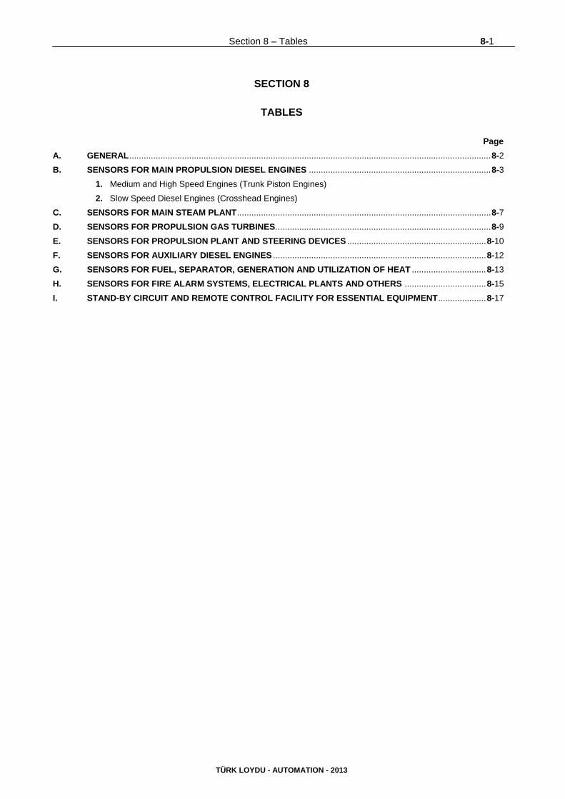
Section 8 – Tables 8-1
TÜRK LOYDU - AUTOMATION - 2013
SECTION 8
TABLES
Page
A. GENERAL ....................................................................................................................................................... 8-2
B. SENSORS FOR MAIN PROPULSION DIESEL ENGINES ............................................................................ 8-3
1. Medium and High Speed Engines (Trunk Piston Engines)
2. Slow Speed Diesel Engines (Crosshead Engines)
C. SENSORS FOR MAIN STEAM PLANT .......................................................................................................... 8-7
D. SENSORS FOR PROPULSION GAS TURBINES. ......................................................................................... 8-9
E. SENSORS FOR PROPULSION PLANT AND STEERING DEVICES .......................................................... 8-10
F. SENSORS FOR AUXILIARY DIESEL ENGINES ......................................................................................... 8-12
G. SENSORS FOR FUEL, SEPARATOR, GENERATION AND UTILIZATION OF HEAT ............................... 8-13
H. SENSORS FOR FIRE ALARM SYSTEMS, ELECTRICAL PLANTS AND OTHERS .................................. 8-15
I. STAND-BY CIRCUIT AND REMOTE CONTROL FACILITY FOR ESSENTIAL EQUIPMENT .................... 8-17
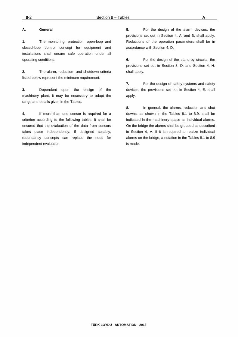
8-2 Section 8 – Tables A
TÜRK LOYDU - AUTOMATION - 2013
A. General
1. The monitoring, protection, open-loop and
closed-loop control concept for equipment and
installations shall ensure safe operation under all
operating conditions.
2. The alarm, reduction- and shutdown criteria
listed below represent the minimum requirement.
3. Dependent upon the design of the
machinery plant, it may be necessary to adapt the
range and details given in the Tables.
4. If more than one sensor is required for a
criterion according to the following tables, it shall be
ensured that the evaluation of the data from sensors
takes place independently. If designed suitably,
redundancy concepts can replace the need for
independent evaluation.
5. For the design of the alarm devices, the
provisions set out in Section 4, A. and B. shall apply.
Reductions of the operation parameters shall be in
accordance with Section 4, D.
6. For the design of the stand-by circuits, the
provisions set out in Section 3, D. and Section 4, H.
shall apply.
7. For the design of safety systems and safety
devices, the provisions set out in Section 4, E. shall
apply.
8. In general, the alarms, reduction and shut
downs, as shown in the Tables 8.1 to 8.9, shall be
indicated in the machinery space as individual alarms.
On the bridge the alarms shall be grouped as described
in Section 4, A. If it is required to realize individual
alarms on the bridge, a notation in the Tables 8.1 to 8.9
is made.
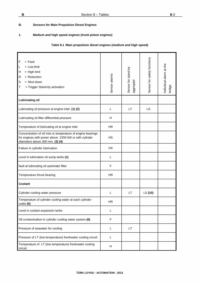
B Section 8 – Tables 8-3
TÜRK LOYDU - AUTOMATION - 2013
B. Sensors for Main Propulsion Diesel Engines
1. Medium and high speed engines (trunk piston engines)
Table 8.1 Main propulsion diesel engines (medium and high speed)
F = Fault
L = Low limit
H = High limit
R = Reduction
S = Shut down
T = Trigger Stand-by activation
Sen
sor
ala
rms
Sen
sor
for
stan
d-by
aggr
egat
e
Sen
sor
for
safe
ty f
unct
ions
Indi
vidu
al a
larm
at t
he
brid
ge
Lubricating oil
Lubricating oil pressure at engine inlet (1) (2) L LT LS
Lubricating oil filter differential pressure H
Temperature of lubricating oil at engine inlet HR
Concentration of oil mist or temperature of engine bearings for engines with power above 2250 kW or with cylinder diameters above 300 mm. (3) (4)
HS
Failure in cylinder lubrication FR
Level in lubrication oil sump tanks (1) L
fault at lubricating oil automatic filter F
Temperature thrust bearing HR
Coolant
Cylinder cooling water pressure L LT LS (10)
Temperature of cylinder cooling water at each cylinder outlet (5)
HR
Level in coolant expansion tanks L
Oil contamination in cylinder cooling water system (6) F
Pressure of seawater for cooling L LT
Pressure of LT (low temperature) freshwater cooling circuit L
Temperature of LT (low temperature) freshwater cooling circuit
H
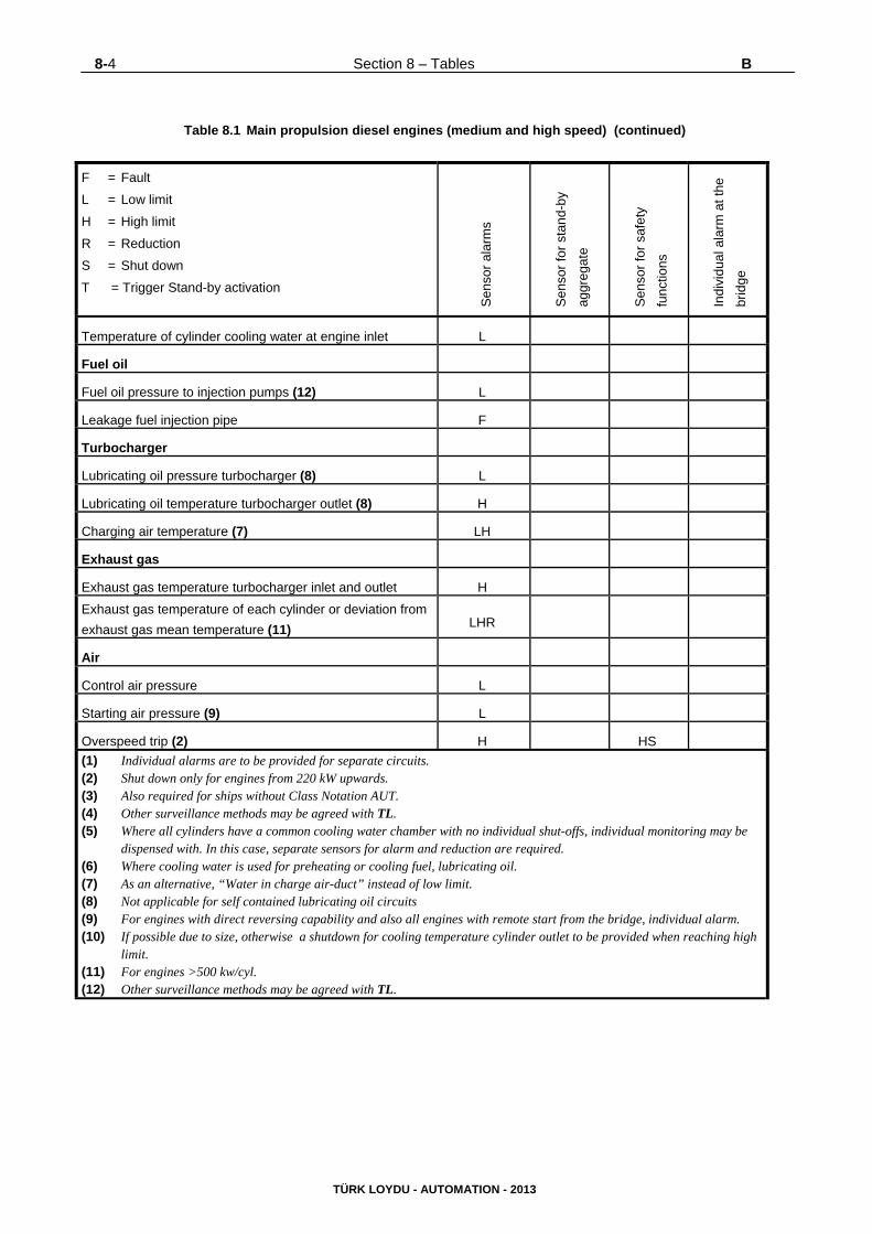
8-4 Section 8 – Tables B
TÜRK LOYDU - AUTOMATION - 2013
Table 8.1 Main propulsion diesel engines (medium and high speed) (continued)
F = Fault
L = Low limit
H = High limit
R = Reduction
S = Shut down
T = Trigger Stand-by activation
Sen
sor
ala
rms
Sen
sor
for
stan
d-by
aggr
egat
e
Sen
sor
for
safe
ty
func
tions
Indi
vidu
al a
larm
at t
he
brid
ge
Temperature of cylinder cooling water at engine inlet L
Fuel oil
Fuel oil pressure to injection pumps (12) L
Leakage fuel injection pipe F
Turbocharger
Lubricating oil pressure turbocharger (8) L
Lubricating oil temperature turbocharger outlet (8) H
Charging air temperature (7) LH
Exhaust gas
Exhaust gas temperature turbocharger inlet and outlet H
Exhaust gas temperature of each cylinder or deviation from
exhaust gas mean temperature (11) LHR
Air
Control air pressure L
Starting air pressure (9) L
Overspeed trip (2) H HS
(1) Individual alarms are to be provided for separate circuits. (2) Shut down only for engines from 220 kW upwards. (3) Also required for ships without Class Notation AUT. (4) Other surveillance methods may be agreed with TL. (5) Where all cylinders have a common cooling water chamber with no individual shut-offs, individual monitoring may be
dispensed with. In this case, separate sensors for alarm and reduction are required. (6) Where cooling water is used for preheating or cooling fuel, lubricating oil. (7) As an alternative, “Water in charge air-duct” instead of low limit. (8) Not applicable for self contained lubricating oil circuits (9) For engines with direct reversing capability and also all engines with remote start from the bridge, individual alarm. (10) If possible due to size, otherwise a shutdown for cooling temperature cylinder outlet to be provided when reaching high
limit. (11) For engines >500 kw/cyl. (12) Other surveillance methods may be agreed with TL.
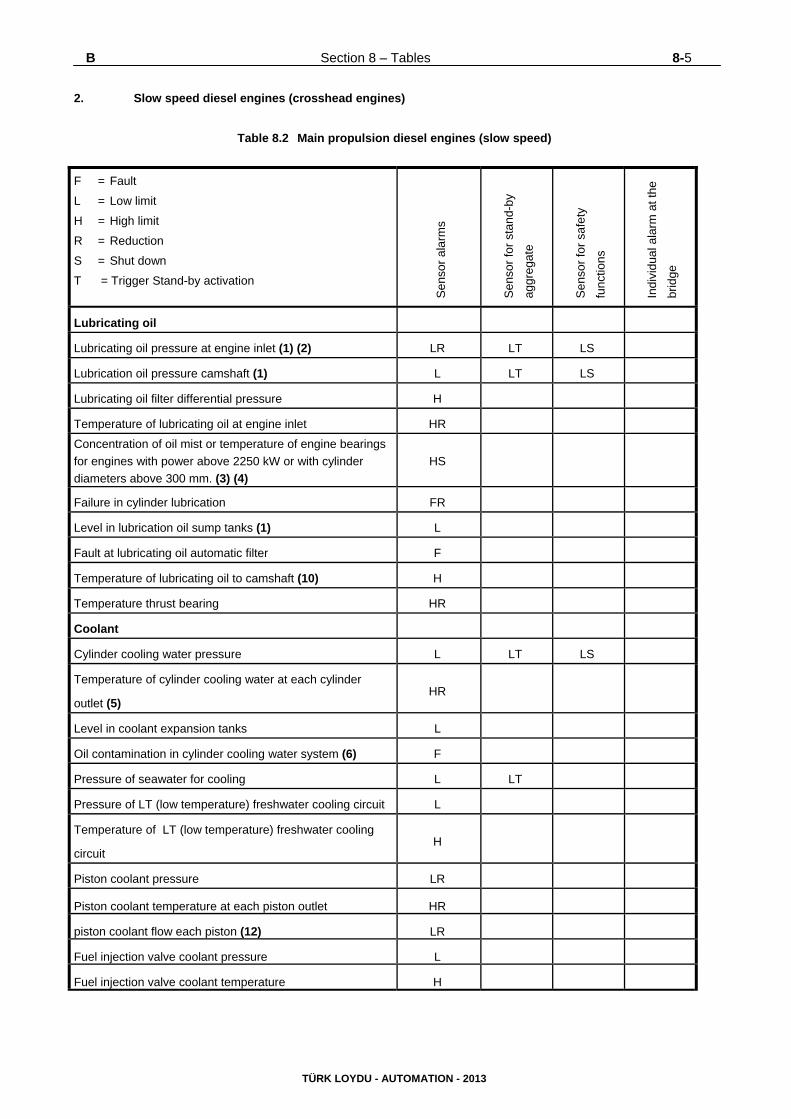
B Section 8 – Tables 8-5
TÜRK LOYDU - AUTOMATION - 2013
2. Slow speed diesel engines (crosshead engines)
Table 8.2 Main propulsion diesel engines (slow speed)
F = Fault
L = Low limit
H = High limit
R = Reduction
S = Shut down
T = Trigger Stand-by activation
Sen
sor
ala
rms
Sen
sor
for
stan
d-by
aggr
egat
e
Sen
sor
for
safe
ty
func
tions
Indi
vidu
al a
larm
at t
he
brid
ge
Lubricating oil
Lubricating oil pressure at engine inlet (1) (2) LR LT LS
Lubrication oil pressure camshaft (1) L LT LS
Lubricating oil filter differential pressure H
Temperature of lubricating oil at engine inlet HR
Concentration of oil mist or temperature of engine bearings
for engines with power above 2250 kW or with cylinder
diameters above 300 mm. (3) (4)
HS
Failure in cylinder lubrication FR
Level in lubrication oil sump tanks (1) L
Fault at lubricating oil automatic filter F
Temperature of lubricating oil to camshaft (10) H
Temperature thrust bearing HR
Coolant
Cylinder cooling water pressure L LT LS
Temperature of cylinder cooling water at each cylinder
outlet (5) HR
Level in coolant expansion tanks L
Oil contamination in cylinder cooling water system (6) F
Pressure of seawater for cooling L LT
Pressure of LT (low temperature) freshwater cooling circuit L
Temperature of LT (low temperature) freshwater cooling
circuit H
Piston coolant pressure LR
Piston coolant temperature at each piston outlet HR
piston coolant flow each piston (12) LR
Fuel injection valve coolant pressure L
Fuel injection valve coolant temperature H
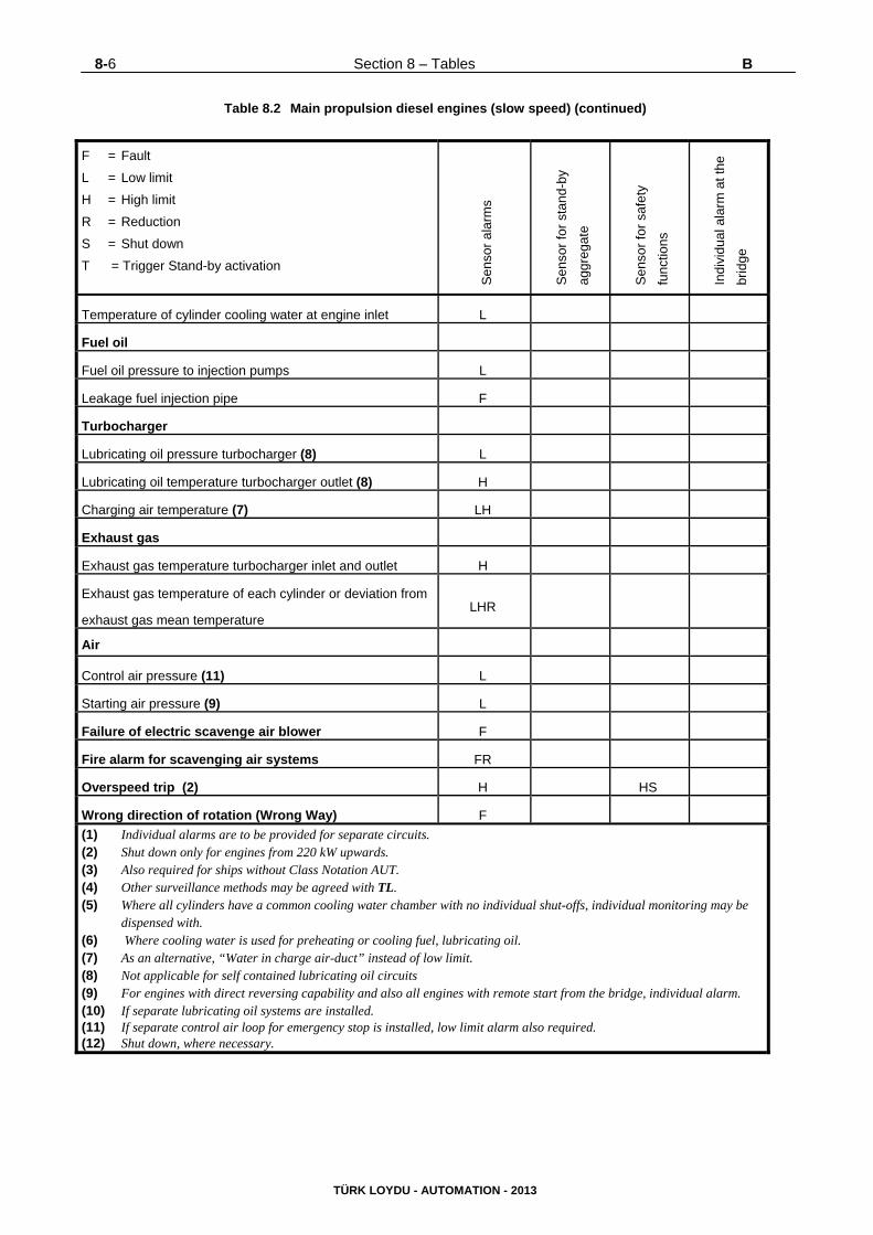
8-6 Section 8 – Tables B
TÜRK LOYDU - AUTOMATION - 2013
Table 8.2 Main propulsion diesel engines (slow speed) (continued)
F = Fault
L = Low limit
H = High limit
R = Reduction
S = Shut down
T = Trigger Stand-by activation
Sen
sor
ala
rms
Sen
sor
for
stan
d-by
aggr
egat
e
Sen
sor
for
safe
ty
func
tions
Indi
vidu
al a
larm
at t
he
brid
ge
Temperature of cylinder cooling water at engine inlet L
Fuel oil
Fuel oil pressure to injection pumps L
Leakage fuel injection pipe F
Turbocharger
Lubricating oil pressure turbocharger (8) L
Lubricating oil temperature turbocharger outlet (8) H
Charging air temperature (7) LH
Exhaust gas
Exhaust gas temperature turbocharger inlet and outlet H
Exhaust gas temperature of each cylinder or deviation from
exhaust gas mean temperature LHR
Air
Control air pressure (11) L
Starting air pressure (9) L
Failure of electric scavenge air blower F
Fire alarm for scavenging air systems FR
Overspeed trip (2) H HS
Wrong direction of rotation (Wrong Way) F
(1) Individual alarms are to be provided for separate circuits. (2) Shut down only for engines from 220 kW upwards. (3) Also required for ships without Class Notation AUT. (4) Other surveillance methods may be agreed with TL. (5) Where all cylinders have a common cooling water chamber with no individual shut-offs, individual monitoring may be
dispensed with. (6) Where cooling water is used for preheating or cooling fuel, lubricating oil. (7) As an alternative, “Water in charge air-duct” instead of low limit. (8) Not applicable for self contained lubricating oil circuits (9) For engines with direct reversing capability and also all engines with remote start from the bridge, individual alarm. (10) If separate lubricating oil systems are installed. (11) If separate control air loop for emergency stop is installed, low limit alarm also required. (12) Shut down, where necessary.
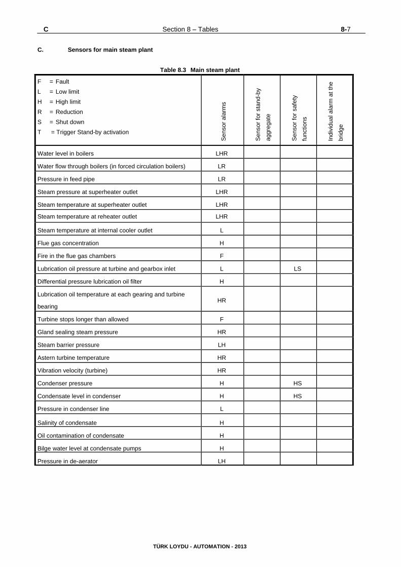
C Section 8 – Tables 8-7
TÜRK LOYDU - AUTOMATION - 2013
C. Sensors for main steam plant
Table 8.3 Main steam plant
F = Fault
L = Low limit
H = High limit
R = Reduction
S = Shut down
T = Trigger Stand-by activation
Sen
sor
ala
rms
Sen
sor
for
stan
d-by
aggr
egat
e
Sen
sor
for
safe
ty
func
tions
Indi
vidu
al a
larm
at t
he
brid
ge
Water level in boilers LHR
Water flow through boilers (in forced circulation boilers) LR
Pressure in feed pipe LR
Steam pressure at superheater outlet LHR
Steam temperature at superheater outlet LHR
Steam temperature at reheater outlet LHR
Steam temperature at internal cooler outlet L
Flue gas concentration H
Fire in the flue gas chambers F
Lubrication oil pressure at turbine and gearbox inlet L LS
Differential pressure lubrication oil filter H
Lubrication oil temperature at each gearing and turbine
bearing HR
Turbine stops longer than allowed F
Gland sealing steam pressure HR
Steam barrier pressure LH
Astern turbine temperature HR
Vibration velocity (turbine) HR
Condenser pressure H HS
Condensate level in condenser H HS
Pressure in condenser line L
Salinity of condensate H
Oil contamination of condensate H
Bilge water level at condensate pumps H
Pressure in de-aerator LH
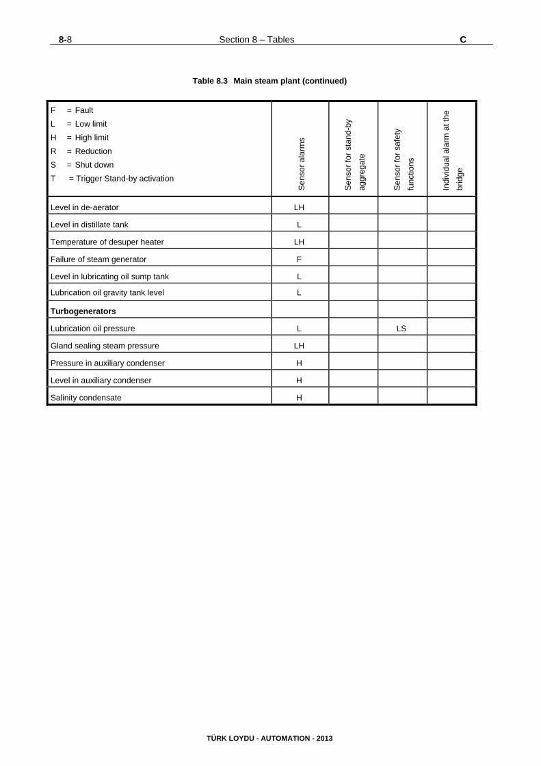
8-8 Section 8 – Tables C
TÜRK LOYDU - AUTOMATION - 2013
Table 8.3 Main steam plant (continued)
F = Fault
L = Low limit
H = High limit
R = Reduction
S = Shut down
T = Trigger Stand-by activation
Sen
sor
ala
rms
Sen
sor
for
stan
d-by
aggr
egat
e
Sen
sor
for
safe
ty
func
tions
Indi
vidu
al a
larm
at t
he
brid
ge
Level in de-aerator LH
Level in distillate tank L
Temperature of desuper heater LH
Failure of steam generator F
Level in lubricating oil sump tank L
Lubrication oil gravity tank level L
Turbogenerators
Lubrication oil pressure L LS
Gland sealing steam pressure LH
Pressure in auxiliary condenser H
Level in auxiliary condenser H
Salinity condensate H
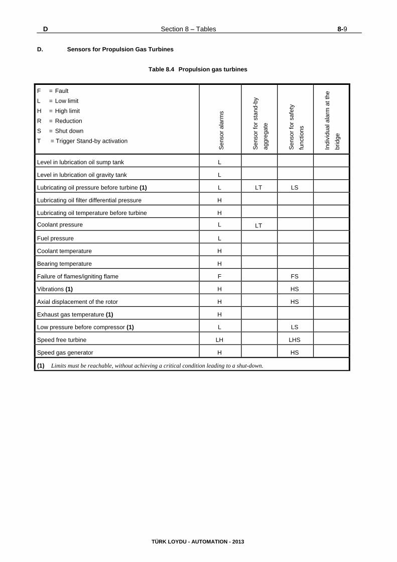
D Section 8 – Tables 8-9
TÜRK LOYDU - AUTOMATION - 2013
D. Sensors for Propulsion Gas Turbines
Table 8.4 Propulsion gas turbines
F = Fault
L = Low limit
H = High limit
R = Reduction
S = Shut down
T = Trigger Stand-by activation
Sen
sor
ala
rms
Sen
sor
for
stan
d-by
aggr
egat
e
Sen
sor
for
safe
ty
func
tions
Indi
vidu
al a
larm
at t
he
brid
ge
Level in lubrication oil sump tank L
Level in lubrication oil gravity tank L
Lubricating oil pressure before turbine (1) L LT LS
Lubricating oil filter differential pressure H
Lubricating oil temperature before turbine H
Coolant pressure L LT
Fuel pressure L
Coolant temperature H
Bearing temperature H
Failure of flames/igniting flame F FS
Vibrations (1) H HS
Axial displacement of the rotor H HS
Exhaust gas temperature (1) H
Low pressure before compressor (1) L LS
Speed free turbine LH LHS
Speed gas generator H HS
(1) Limits must be reachable, without achieving a critical condition leading to a shut-down.
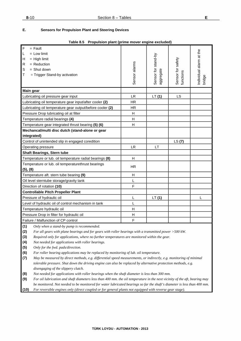
8-10 Section 8 – Tables E
TÜRK LOYDU - AUTOMATION - 2013
E. Sensors for Propulsion Plant and Steering Devices
Table 8.5 Propulsion plant (prime mover engine excluded)
F = Fault
L = Low limit
H = High limit
R = Reduction
S = Shut down
T = Trigger Stand-by activation
Sen
sor
ala
rms
Sen
sor
for
stan
d-by
aggr
egat
e
Sen
sor
for
safe
ty
func
tions
Indi
vidu
al a
larm
at t
he
brid
ge
Main gear
Lubricating oil pressure gear input LR LT (1) LS
Lubricating oil temperature gear input/after cooler (2) HR
Lubricating oil temperature gear output/before cooler (2) HR
Pressure Drop lubricating oil at filter H
Temperature radial bearings (4) H
Temperature gear integrated thrust bearing (5) (6) H
Mechancal/multi disc dutch (stand-alone or gear
integrated)
Control of unintended slip in engaged coredition LS (7)
Operating pressure LR LT
Shaft Bearings, Stern tube
Temperature or lub. oil temperature radial bearings (8) H
Temperature or lub. oil temperaturethrust bearings
(5), (8) HR
Temperature aft. stern tube bearing (9) H
Oil level sterntube storage/gravity tank L
Direction of rotation (10) F
Controllable Pitch Propeller Plant
Pressure of hydraulic oil L LT (1) L
Level of hydraulic oil of control mechanism in tank L
Temperature hydraulic oil H
Pressure Drop in filter for hydraulic oil H
Failure / Malfunction of CP control F
(1) Only when a stand-by pump is recommended.
(2) For all gears with plane bearings and for gears with roller bearings with a transmitted power >500 kW.
(3) Required only for applications, where no further temperatures are monitored within the gear.
(4) Not needed for applications with roller bearings.
(5) Only for the fwd. pads/direction.
(6) For roller bearing applications may be replaced by monitoring of lub. oil temperature.
(7) May be measured by direct methods, e.g. differential speed measurements, or indirectly, e.g. monitoring of minimal
tolerable pressure. Shut down the driving engine can also be replaced by alternative protection methods, e.g.
disengaging of the slippery clutch.
(8) Not needed for applications with roller bearings when the shaft diameter is less than 300 mm.
(9) For oil lubrication and shaft diameters less than 400 mm. the oil temperature in the next vicinity of the aft, bearing may
be monitored. Not needed to be monitored for water lubricated bearings so far the shaft’s diameter is less than 400 mm.
(10) For reversible engines only (direct coupled or for general plants not equipped with reverse gear stage).
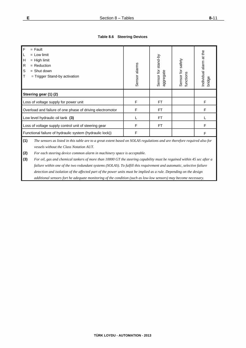
E Section 8 – Tables 8-11
TÜRK LOYDU - AUTOMATION - 2013
Table 8.6 Steering Devices
F = Fault
L = Low limit
H = High limit
R = Reduction
S = Shut down
T = Trigger Stand-by activation
Sen
sor
ala
rms
Sen
sor
for
stan
d-by
aggr
egat
e
Sen
sor
for
safe
ty
func
tions
Indi
vidu
al a
larm
at t
he
brid
ge
Steering gear (1) (2)
Loss of voltage supply for power unit F FT F
Overload and failure of one phase of driving electromotor F FT F
Low level hydraulic oil tank (3) L FT L
Loss of voltage supply control unit of steering gear F FT F
Functional failure of hydraulic system (hydraulic lock)) F F
(1) The sensors as listed in this table are to a great extent based on SOLAS regulations and are therefore required also for
vessels without the Class Notation AUT.
(2) For each steering device common alarm in machinery space is acceptable.
(3) For oil, gas and chemical tankers of more than 10000 GT the steering capability must be regained within 45 sec after a
failure within one of the two redundant systems (SOLAS). To fulfill this requirement and automatic, selective failure
detection and isolation of the affected part of the power units must be implied as a rule. Depending on the design
additional sensors fort he adequate monitoring of the condition (such as low-low sensors) may become necessary.
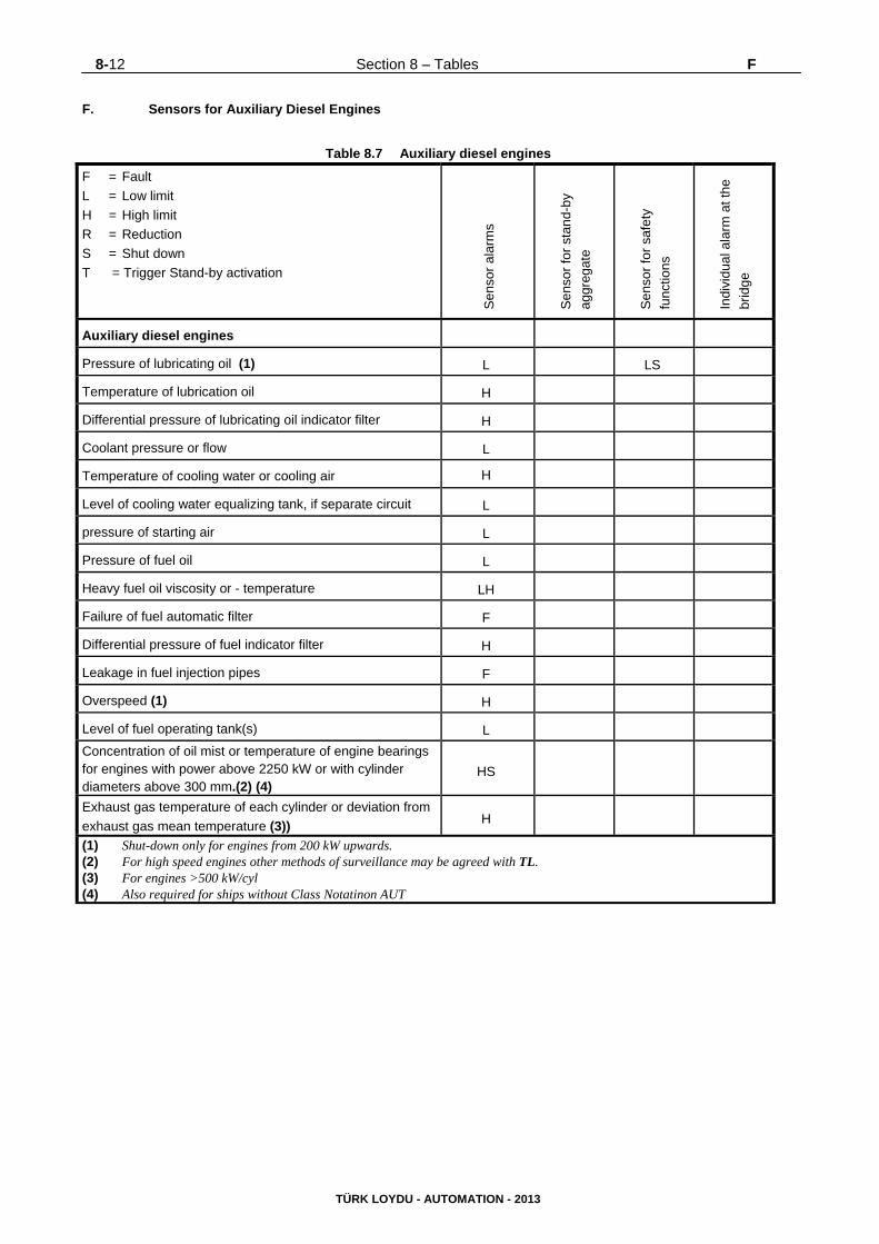
8-12 Section 8 – Tables F
TÜRK LOYDU - AUTOMATION - 2013
F. Sensors for Auxiliary Diesel Engines
Table 8.7 Auxiliary diesel engines
F = Fault
L = Low limit
H = High limit
R = Reduction
S = Shut down
T = Trigger Stand-by activation
Sen
sor
ala
rms
Sen
sor
for
stan
d-by
aggr
egat
e
Sen
sor
for
safe
ty
func
tions
Indi
vidu
al a
larm
at t
he
brid
ge
Auxiliary diesel engines
Pressure of lubricating oil (1) L LS
Temperature of lubrication oil H
Differential pressure of lubricating oil indicator filter H
Coolant pressure or flow L
Temperature of cooling water or cooling air H
Level of cooling water equalizing tank, if separate circuit L
pressure of starting air L
Pressure of fuel oil L
Heavy fuel oil viscosity or - temperature LH
Failure of fuel automatic filter F
Differential pressure of fuel indicator filter H
Leakage in fuel injection pipes F
Overspeed (1) H
Level of fuel operating tank(s) L
Concentration of oil mist or temperature of engine bearings for engines with power above 2250 kW or with cylinder diameters above 300 mm.(2) (4)
HS
Exhaust gas temperature of each cylinder or deviation from
exhaust gas mean temperature (3)) H
(1) Shut-down only for engines from 200 kW upwards. (2) For high speed engines other methods of surveillance may be agreed with TL. (3) For engines >500 kW/cyl (4) Also required for ships without Class Notatinon AUT
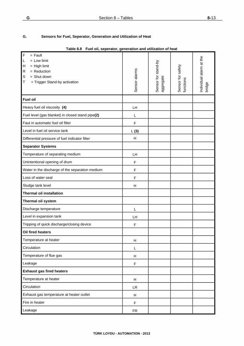
G Section 8 – Tables 8-13
TÜRK LOYDU - AUTOMATION - 2013
G. Sensors for Fuel, Seperator, Generation and Utilization of Heat
Table 8.8 Fuel oil, seperator, generation and utilization of heat
F = Fault
L = Low limit
H = High limit
R = Reduction
S = Shut down
T = Trigger Stand-by activation
Sen
sor
ala
rms
Sen
sor
for
stan
d-by
aggr
egat
e
Sen
sor
for
safe
ty
func
tions
Indi
vidu
al a
larm
at t
he
brid
ge
Fuel oil
Heavy fuel oil viscosity (4) LH
Fuel level (gas blanket) in closed stand pipe(2) L
Faut in automatic fuel oil filter F
Level in fuel oil service tank L (3)
Differential pressure of fuel indicator filter H
Separator Systems
Temperature of separating medium LH
Unintentional opening of drum F
Water in the discharge of the separation medium F
Loss of water seal F
Sludge tank level H
Thermal oil installation
Thermal oil system
Discharge temperature L
Level in expansion tank LH
Tripping of quick discharge/closing device F
Oil fired heaters
Temperature at heater H
Circulation L
Temperature of flue gas H
Leakage F
Exhaust gas fired heaters
Temperature at heater H
Circulation LR
Exhaust gas temperature at heater outlet H
Fire in heater F
Leakage FR
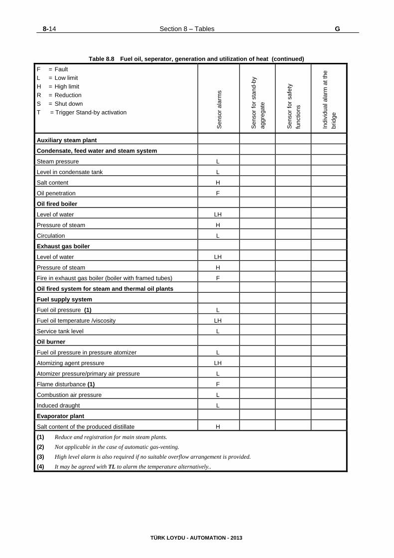
8-14 Section 8 – Tables G
TÜRK LOYDU - AUTOMATION - 2013
Table 8.8 Fuel oil, seperator, generation and utilization of heat (continued)
F = Fault
L = Low limit
H = High limit
R = Reduction
S = Shut down
T = Trigger Stand-by activation
Sen
sor
ala
rms
Sen
sor
for
stan
d-by
aggr
egat
e
Sen
sor
for
safe
ty
func
tions
Indi
vidu
al a
larm
at t
he
brid
ge
Auxiliary steam plant
Condensate, feed water and steam system
Steam pressure L
Level in condensate tank L
Salt content H
Oil penetration F
Oil fired boiler
Level of water LH
Pressure of steam H
Circulation L
Exhaust gas boiler
Level of water LH
Pressure of steam H
Fire in exhaust gas boiler (boiler with framed tubes) F
Oil fired system for steam and thermal oil plants
Fuel supply system
Fuel oil pressure (1) L
Fuel oil temperature /viscosity LH
Service tank level L
Oil burner
Fuel oil pressure in pressure atomizer L
Atomizing agent pressure LH
Atomizer pressure/primary air pressure L
Flame disturbance (1) F
Combustion air pressure L
Induced draught L
Evaporator plant
Salt content of the produced distillate H
(1) Reduce and registration for main steam plants.
(2) Not applicable in the case of automatic gas-venting.
(3) High level alarm is also required if no suitable overflow arrangement is provided.
(4) It may be agreed with TL to alarm the temperature alternatively..
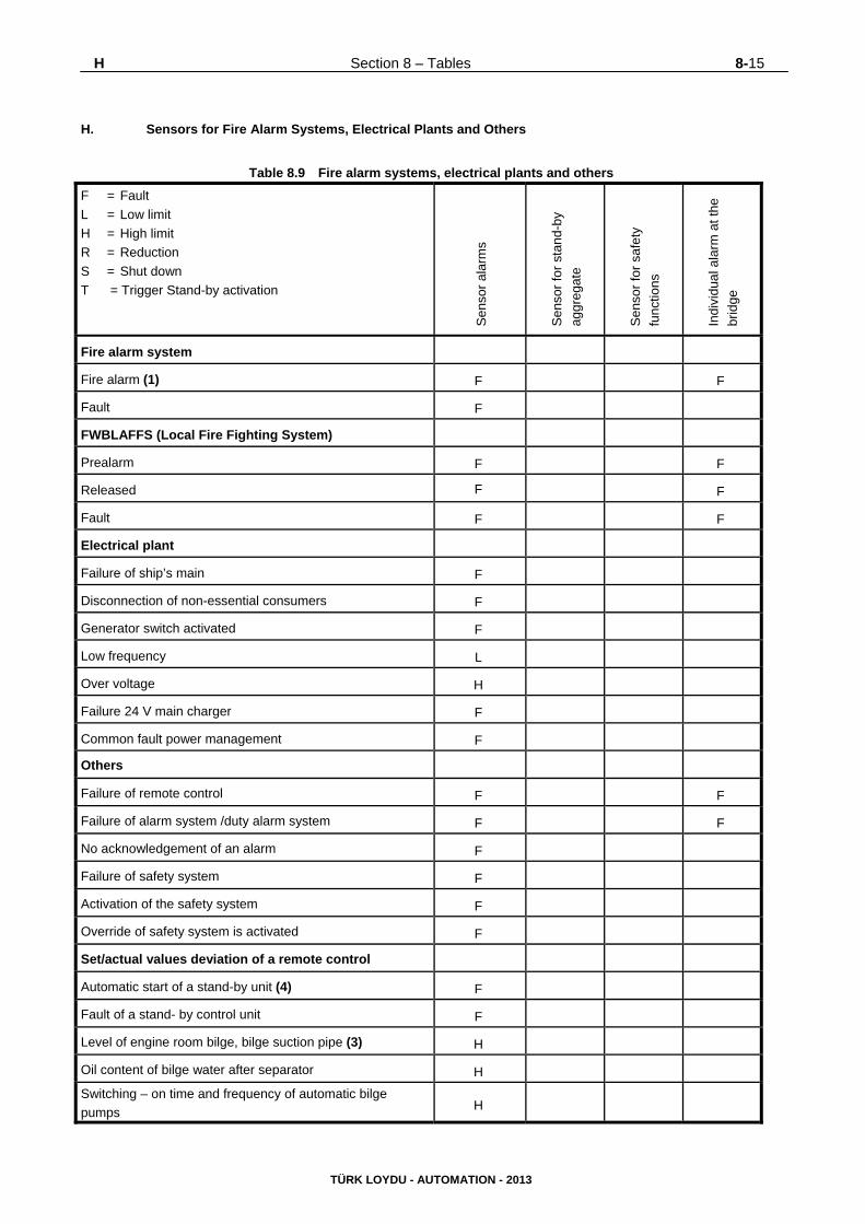
H Section 8 – Tables 8-15
TÜRK LOYDU - AUTOMATION - 2013
H. Sensors for Fire Alarm Systems, Electrical Plants and Others
Table 8.9 Fire alarm systems, electrical plants and others
F = Fault
L = Low limit
H = High limit
R = Reduction
S = Shut down
T = Trigger Stand-by activation
Sen
sor
ala
rms
Sen
sor
for
stan
d-by
aggr
egat
e
Sen
sor
for
safe
ty
func
tions
Indi
vidu
al a
larm
at t
he
brid
ge
Fire alarm system
Fire alarm (1) F F
Fault F
FWBLAFFS (Local Fire Fighting System)
Prealarm F F
Released F F
Fault F F
Electrical plant
Failure of ship’s main F
Disconnection of non-essential consumers F
Generator switch activated F
Low frequency L
Over voltage H
Failure 24 V main charger F
Common fault power management F
Others
Failure of remote control F F
Failure of alarm system /duty alarm system F F
No acknowledgement of an alarm F
Failure of safety system F
Activation of the safety system F
Override of safety system is activated F
Set/actual values deviation of a remote control
Automatic start of a stand-by unit (4) F
Fault of a stand- by control unit F
Level of engine room bilge, bilge suction pipe (3) H
Oil content of bilge water after separator H
Switching – on time and frequency of automatic bilge
pumps H
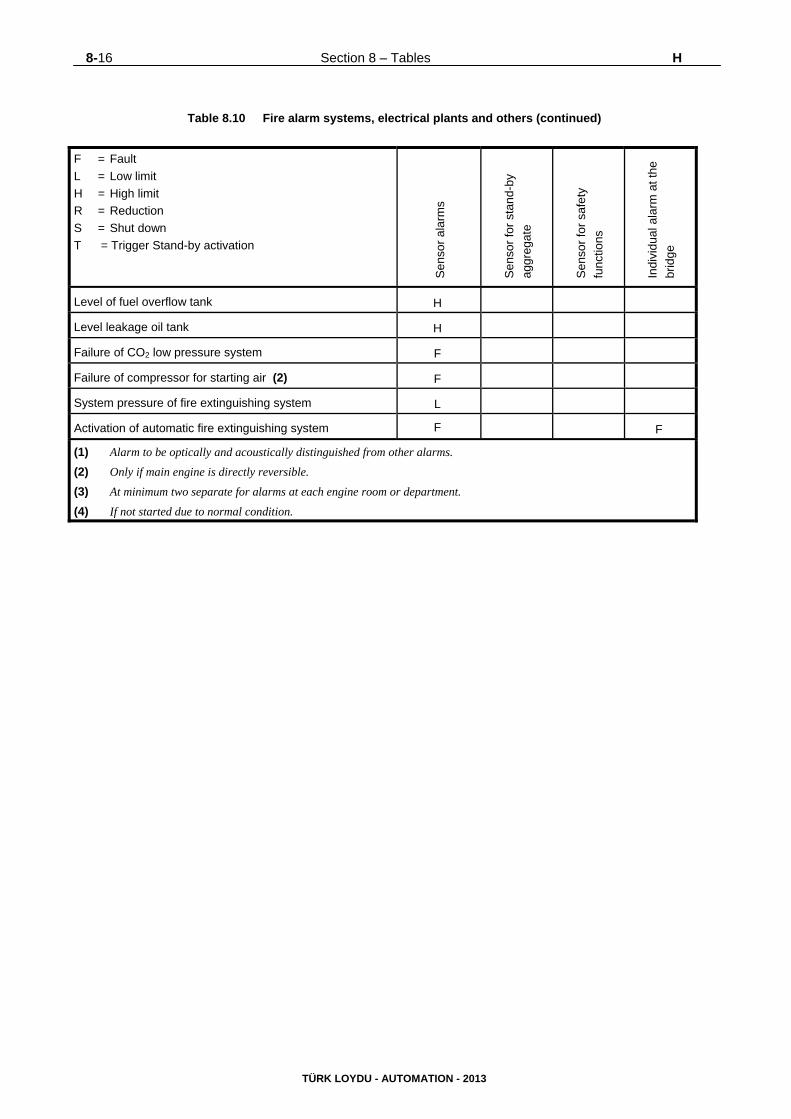
8-16 Section 8 – Tables H
TÜRK LOYDU - AUTOMATION - 2013
Table 8.10 Fire alarm systems, electrical plants and others (continued)
F = Fault
L = Low limit
H = High limit
R = Reduction
S = Shut down
T = Trigger Stand-by activation
Sen
sor
ala
rms
Sen
sor
for
stan
d-by
aggr
egat
e
Sen
sor
for
safe
ty
func
tions
Indi
vidu
al a
larm
at t
he
brid
ge
Level of fuel overflow tank H
Level leakage oil tank H
Failure of CO2 low pressure system F
Failure of compressor for starting air (2) F
System pressure of fire extinguishing system L
Activation of automatic fire extinguishing system F F
(1) Alarm to be optically and acoustically distinguished from other alarms.
(2) Only if main engine is directly reversible.
(3) At minimum two separate for alarms at each engine room or department.
(4) If not started due to normal condition.
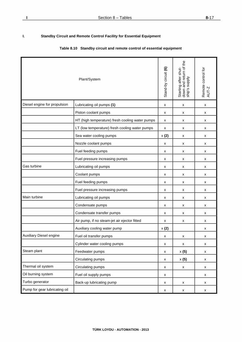
I Section 8 – Tables 8-17
TÜRK LOYDU - AUTOMATION - 2013
I. Standby Circuit and Remote Control Facility for Essential Equipment
Table 8.10 Standby circuit and remote control of essential equipment
Plant/System
Sta
nd-b
y ci
rcui
t (6)
Sta
rtin
g af
ter
shut
-do
wn
and
retu
rn o
f the
sh
ip’s
sup
ply
Rem
ote
cont
rol f
or
AU
T-Z
Diesel engine for propulsion Lubricating oil pumps (1) x x x
Piston coolant pumps x x x
HT (high temperature) fresh cooling water pumps x x x
LT (low temperature) fresh cooling water pumps x x x
Sea water cooling pumps x (2) x x
Nozzle coolant pumps x x x
Fuel feeding pumps x x x
Fuel pressure increasing pumps x x x
Gas turbine Lubricating oil pumps x x x
Coolant pumps x x x
Fuel feeding pumps x x x
Fuel pressure increasing pumps x x x
Main turbine Lubricating oil pumps x x x
Condensate pumps x x x
Condensate transfer pumps x x x
Air pump, if no steam-jet air ejector fitted x x x
Auxiliary cooling water pump x (2) x
Auxiliary Diesel engine Fuel oil transfer pumps x x x
Cylinder water cooling pumps x x x
Steam plant Feedwater pumps x x (5) x
Circulating pumps x x (5) x
Thermal oil system Circulating pumps x x x
Oil burning system Fuel oil supply pumps x x
Turbo generator Back-up lubricating pump x x x
Pump for gear lubricating oil x x x
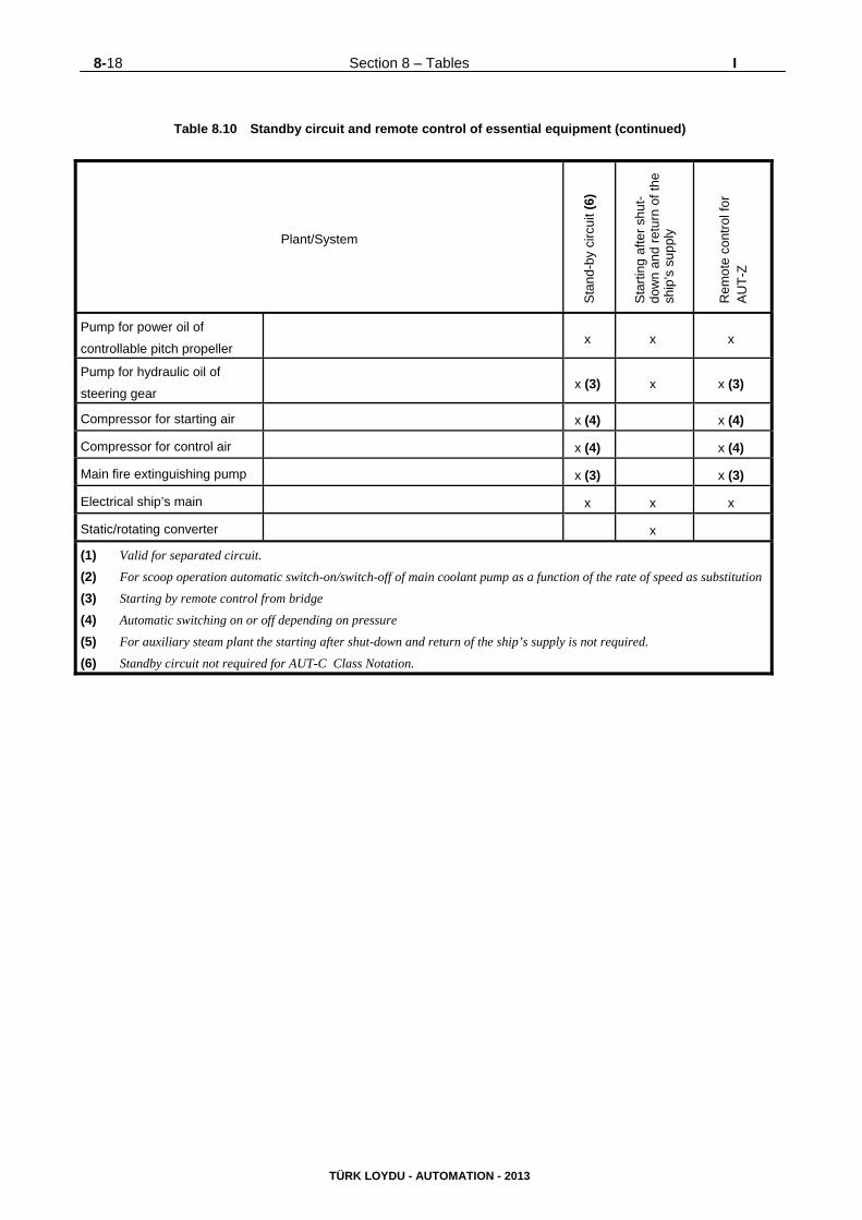
8-18 Section 8 – Tables I
TÜRK LOYDU - AUTOMATION - 2013
Table 8.10 Standby circuit and remote control of essential equipment (continued)
Plant/System
Sta
nd-b
y ci
rcui
t (6)
Sta
rtin
g af
ter
shut
-do
wn
and
retu
rn o
f the
sh
ip’s
sup
ply
Rem
ote
cont
rol f
or
AU
T-Z
Pump for power oil of
controllable pitch propeller x x x
Pump for hydraulic oil of
steering gear
x (3) x x (3)
Compressor for starting air x (4) x (4)
Compressor for control air x (4) x (4)
Main fire extinguishing pump x (3) x (3)
Electrical ship’s main x x x
Static/rotating converter x
(1) Valid for separated circuit.
(2) For scoop operation automatic switch-on/switch-off of main coolant pump as a function of the rate of speed as substitution
(3) Starting by remote control from bridge
(4) Automatic switching on or off depending on pressure
(5) For auxiliary steam plant the starting after shut-down and return of the ship’s supply is not required.
(6) Standby circuit not required for AUT-C Class Notation.