Embed Size (px)
Citation preview

Grand Forks International Airport: Airport Master Plan January 2017 DRAFT Chapter 4 – Facility Requirements Page 4-1
CHAPTER 4: FACILITY REQUIREMENTS
Introduction
This chapter of the Airport Master Plan analyzes the existing and anticipated future facility needs at the Grand Forks International Airport (GFK). The report is divided into sections that assess the needs of primary airport elements including airfield, commercial passenger terminal, general aviation, air cargo, support and landside facilities.
Airside requirements are those necessary for the operation of aircraft. Landside requirements are those necessary to support airport, aircraft and passenger operations. Proposed airport needs are based on a review of existing conditions, capacity levels, activity demand forecasts and airport design standards using FAA guidance and industry standards. This chapter identifies existing facility deficiencies along with facility needs to meet demand through the planning period. The level of review completed is sufficient to identify major elements that should be addressed in this comprehensive airport plan.
This chapter provides a review of the facility needs for the following airport infrastructure categories:
Airside Facilities
Passenger Terminal
Air Cargo
General Aviation
Support Facilities
Landside Facilities
Specific alternatives that propose solutions to address facility needs are evaluated in Chapter 5: Alternatives Analysis.
Background
GFK has completed significant airport improvements to address facility needs since the last master plan study was completed in 2008 including the construction of fourth runway (Runway 9R/27L), construction of a new air carrier terminal building, as well as construction of a new Snow Removal Equipment (SRE) building and Aircraft Rescue and Fire Fighting (ARFF) building. The construction of an east-side general aviation development area began in 2016.
Through coordination with the airport sponsor/airport stakeholders in conjunction with a forecast showing growth, there are key areas in the facility requirements chapter that require emphasis in the future development plans of GFK. These include:
Runway/Airfield Capacity
Passenger Terminal Building Space Requirements
General Aviation Hangar Needs
Automobile Parking Needs
This chapter will explain facility needs at GFK with recommendations based on specific activity-levels or time periods.
Planning Activity Levels (PALs)
There are various airport activity measures used to determine airport facility requirements including passenger enplanements, peak hour activity, annual operations and based aircraft. Airport activity can be sensitive to industry changes, national and local economic conditions. This results in difficulty in identifying a specific calendar year for associated demand-driven improvements.

Grand Forks International Airport: Airport Master Plan January 2017 DRAFT Chapter 4 – Facility Requirements Page 4-2
For this Master Plan study, PALs are used to identify demand thresholds for many recommended facility improvements. If an activity level is approaching a PAL, then the airport should prepare to implement the improvements. Alternatively, activity levels that are not approaching a PAL can allow improvements to be deferred. The demand forecasts developed in this study correspond to an anticipated planning level calendar year to each PAL (2019, 2024, 2029, 2034) from the preferred aviation forecasts as seen in Table 4-1.
Table 4-1 – Planning Activity Levels (PALs) Key Activity Metrics Base PAL 1 PAL 2 PAL 3 PAL 4
Passengers
Annual Enplanements 146,531 147,612 170,763 194,170 220,787
Design Hour Departing 192 193 223 254 289
Design Hour Arriving 192 193 223 254 289
Design Hour Total 363 366 423 481 547
Passenger Airline Operations
Total Operations 4,756 4,251 4,191 4,638 5,097
Design Hour Departures 2.1 1.9 1.9 2.1 2.3
Design Hour Arrivals 2.1 1.9 1.9 2.1 2.3
Design Hour Total 4.2 3.7 3.7 4.1 4.5
Total Airport Operations
Total Operations 324,196 312,613 334,205 347,330 350,477
Design Hour 151 145 155 161 163
Air Cargo
Enplaned/Deplaned Cargo (lbs.) 58,351,637 598,901 620,158 637,620 660,139
Based Aircraft
GFK Based Aircraft 147 160 169 174 179 Source: KLJ Analysis
Exhibit 4-2 graphically depicts the PAL enplanement activity thresholds.
Exhibit 4-2 – Passenger Enplanement Planning Activity Levels (PALs)
Source: KLJ Analysis
125,000
150,000
175,000
200,000
225,000
250,000
Pass
enger
Enpla
nem
ents
Year
GFK Enplanements: Planning Activity Levels (PALs)
Preferred Enplanement ForecastPAL 1
PAL 2
PAL 3
PAL 4

Grand Forks International Airport: Airport Master Plan January 2017 DRAFT Chapter 4 – Facility Requirements Page 4-3
Airside Facil it ies
Airfield Design Standards
Guidance on FAA airport design standards is found in FAA AC 150/5300-13A, Airport Design (Change 1). Airport design standards provide basic guidelines for a safe, efficient, and economic airport system. Careful selection of basic aircraft characteristics for which the airport will be designed is important. Airport designs based only on existing aircraft can severely limit the ability to expand the airport to meet future requirements for larger, more demanding aircraft. Airport designs that are based on large aircraft unlikely to operate at the airport are not economical.
CRITICAL DESIGN AIRCRAFT
Aircraft characteristics relate directly to the design standards of an airport. Planning airport improvements requires the selection of one or more “critical design aircraft.” The critical design aircraft is the most demanding aircraft fleet operating or forecast to operate at the airport on a regular basis. FAA design standards for an airport are determined by a coding system that relates the physical and operational characteristics of the design aircraft to the airfield design geometry.
It is not the usual practice to base the airport design on an aircraft that uses the airport infrequently. Projects are eligible for FAA funding if they are needed for the critical design aircraft. The minimum threshold is 500 annual itinerant operations. See discussion further in this chapter regarding the critical design aircraft at GFK.
AIRFIELD DESIGN CLASSIFICATIONS
The FAA has established aircraft classification systems that group aircraft types based on their performance and geometric characteristics. These classification systems (see Exhibit 4-3) are used to determine the appropriate airport design standards for specific runway, taxiway, apron, or other facilities, as described in FAA AC 150/5300-13A, Change 1.
Aircraft Approach Category (AAC): a grouping of aircraft based on approach reference speed, typically 1.3 times the stall speed. Approach speed affects the dimensions and size of runway safety and object free areas.
Airplane Design Group (ADG): a classification of aircraft based on wingspan and tail height. When the aircraft wingspan and tail height fall in different groups, the higher group is used. Wingspan affects the dimensions of taxiway and apron object free areas, as well as apron and parking configurations.
Taxiway Design Group (TDG): a classification of airplanes based on outer to outer Main
Gear Width (MGW) and Cockpit to Main Gear (CMG) distance. TDG affects taxiway/taxilane
pavement width and fillet design at intersections.
Approach Visibility Minimums: relates to the visibility minimums expressed by Runway Visual Range (RVR) values in feet. This is the minimum distance pilots must be able to see the runway to execute an approach to land. Visibility categories include visual (V), non-precision (NPA), approach procedure with vertical guidance (APV) and precision (PA). Lower visibility minimums require more complex airfield infrastructure and enhanced protection areas.
Although not a classification, runway length is driven by the landing and departure performance characteristics of the most demanding design aircraft as identified in FAA AC 5325-4B, Runway Length Recommendations for Airport Design.
AIRPORT REFERENCE CODE (ARC)
The Airport Reference Code (ARC) is an airport designation that represents the AAC and ADG of the aircraft that the entire airfield is intended to accommodate on a regular basis. The ARC is used for

Grand Forks International Airport: Airport Master Plan January 2017 DRAFT Chapter 4 – Facility Requirements Page 4-4
planning and design only and does not limit the aircraft that may be able to operate safely on the airport.
RUNWAY DESIGN CODE (RDC)
RDC is a code signifying the design standards to which the overall runway is to be planned and built, typical based on the design aircraft and approach visibility minimums for a particular runway. RDC provides the information needed to determine the design standards that apply.
RUNWAY REFERENCE CODE (RRC)
RRC is a code signifying the current operational capabilities of each specific runway end and adjacent parallel taxiway. RRC is split into Approach Reference Code (APRC) and Departure Reference Codes (DPRC) for each phase of flight. APRC classifications are expressed in three components: AAC, ADG, and the lowest approach visibility minimums that either end of the runway is planned to provide. DPRC classifications utilize AAC and ADG components only. A runway end may have more than one RRC depending on the minimums available to a specific AAC.
Exhibit 4-3 – Airfield Classification Systems Aircraft Approach Category (AAC)
AAC Approach Speed
A Approach speed less than 91 knots
B Approach speed 91 knots or more but less than 121 knots
C Approach speed 121 knots or more but less than 141 knots
D Approach speed 141 knots or more but less than 166 knots
E Approach speed 166 knots or more
Airplane Design Group (ADG)
ADG Tail Height (ft.) Wingspan (ft.)
I < 20’ < 49’
II 20’ - < 30’ 49’ - < 79’
III 30’ - < 45’ 79’ - < 118’
IV 45’ - < 60’ 118’ - < 171’
V 60’ - < 66’ 171’ - < 214’
IV 66’ - < 80’ 214’ - < 262’
Approach Visibility Minimums
RVR (ft.)* Instrument Flight Visibility Category (statue mile)
N/A (VIS) Visual (V)
5000 Not lower than 1 mile (NPA)
4000 Lower than 1 mile but not lower than ¾ mile (APV)
2400 Lower than ¾ mile but not lower than ½ mile (CAT-I PA)
1600 Lower than ½ mile but not lower than ¼ mile (CAT-II PA)
1200 Lower than ¼ mile (CAT-III PA) Source: FAA AC 150/5300-13A – Change 1, Airport Design; *RVR values are not exact equivalents APV = Approach with Vertical Guidance, PA = Precision Approach
TAXIWAY DESIGN GROUP (TDG)
TDG relates to the dimensions of the aircraft landing gear including distance from cockpit to main gear (CMG) or wheelbase and main gear width (MGW). These dimensions relate to an aircraft’s ability to safely maneuver taxiways at an airport. Taxiways/taxilanes on an airport can be construct to a different TDG based on the expected use of that taxiway/taxilane by the design aircraft. See Exhibit 4-4 for TDG standards.
Grand Forks International Airport: Airport Master Plan January 2017 DRAFT Chapter 4 – Facility Requirements Page 4-5
Exhibit 4-4 – Taxiway Design Group
Source: FAA AC 150/5300-13A – Change 1, Airport Design
OTHER DESIGN CONSIDERATIONS
Other airport design principles are important to consider for a safe and efficient airport design:
Runway/Taxiway Configuration: The configuration of runways and taxiways affects the airport’s capacity/delay, risk of incursions with other aircraft on the runway and overall operational safety. Location of and type of taxiways connecting with runways correlates to runway occupancy time. The design of taxiway infrastructure should promote safety by minimizing confusing or complex geometry to reduce risk of an aircraft inadvertently entering the runway environment.
Approach and Departure Airspace & Land Use: Runways each have imaginary surfaces that extend upward and outward from the runway end to protect normal flight operations. Runways also have land use standards beyond the runway end to protect the flying public as well as persons and property on the ground from potential operational hazards. Runways must meet grading and clearance standards considering natural and man-made obstacles that may obstruct these airspace surfaces. Surrounding land use should be compatible with airport operations. Airports should develop comprehensive land use controls to prevent new hazards outside the airport property line. Obstructions can limit the utility of a runway.
Meteorological Conditions: An airport’s runways should be designed so that aircraft land and takeoff into the prevailing wind. As wind conditions change, the addition of an additional runway may be needed to mitigate the effects of significant crosswind conditions that occur more than five percent of the year. Airports that experience lower cloud ceiling and/or visibility should also consider implementing an instrument procedures and related navigational aids to runways to maximize airport utility.
Controller Line of Sight: The local Airport Traffic Control Tower (ATCT) relies on a clear line of sight from the controller cab to the airport’s movement areas which includes the runways, taxiways, aprons and arrival/departure corridors. Structures on an airport need to consider this design standard, and in some cases require the completion of a shadow study to demonstrate no adverse impact.
Navigation Aids & Critical Areas: Visual navigational aids (NAVAIDs) to a runway or the airfield require necessary clear areas for these NAVAIDs to be effective for pilots. Instrument NAVAIDs on an airport require sufficient clear areas for the NAVAID to properly function without
Grand Forks International Airport: Airport Master Plan January 2017 DRAFT Chapter 4 – Facility Requirements Page 4-6
interference to provide guidance to pilots. These NAVAID protection areas restrict development.
Airfield Line of Sight: Runways need to meet grading standards so that objects and aircraft can be seen along the entire runway. A clear line of sight is also required for intersecting runways within the Runway Visibility Zone to allow pilots to maintain visual contact with other objects and/or aircraft that may pose a hazard.
Interface with Landside: The airfield configuration should be designed to provide for the safe and efficient operation of aircraft as they transition from the airfield to landside facilities such as hangars and terminals.
Environmental Factors: Airport development must consider potential impacts in and around the airport environs through the National Environmental Policy Act (NEPA). Additionally, development should also reduce the risk of potential wildlife hazards such as deer and birds that may cause hazards to flight operations.
Critical Design Aircraft
The critical design aircraft types must be identified to determine the appropriate airport design standards to incorporate into airport planning. The existing and future critical design aircraft characteristics at GFK are summarized in the following sections. Exhibit 4-5 provides a breakdown of examples aircraft types and Airport Reference Code (ARC) characteristics.
OPERATIONAL BREAKDOWN
Passenger Airlines Table 4-5 summarizes GFK scheduled passenger design aircraft operations. The design aircraft for scheduled & unscheduled passenger aircraft is currently an ARC D-III, TDG-4 airplane transitioning to an ARC C-III, TDG-3 airplane in the future. The heaviest aircraft to regularly use the airport will transition from maximum aircraft weight will transition from 166,000 pounds to 172,000 pounds in the future (dual wheel).
Table 4-5 – Scheduled Passenger Design Aircraft Operations Breakdown Representative Aircraft Design Base PAL 1 PAL 2 PAL 3 PAL 4
Boeing MD-83 (Allegiant) ARC D-III, TDG-4 456 416 286 0 0
CRJ-200 (Delta) ARC D-II, TDG-3 3,526 1,716 624 0 0
Boeing 757-200 (Allegiant) ARC C-IV, TDG-4 60 31 31 0 0
Airbus A319/A320 (Allegiant) ARC C-III, TDG-3 326 416 858 1,196 1,248
Boeing 717-200 (Delta) ARC C-III, TDG-3 0 10 10 10 530
CRJ-900 (Delta) ARC C-III, TDG-3 320 1,664 2,392 3,432 3,328
Aircraft Approach Category Total AAC D 3,982 2,132 910 0 0
Total AAC C 706 2,122 3,292 4,638 5,106
Airplane Design Group Total ADG-III 1,102 2,506 3,546 4,638 5,106
Taxiway Design Group Total TDG-4 516 447 317 0 0
Total TDG-3 4,172 3,806 3,884 4,638 5,106 Source: KLJ Analysis, FAA Traffic Flow Management System (2014) Aircraft operations exceeding FAA regular use threshold are shown in Green
Calendar Year 2015 FAA Traffic Flow Management System (TFMSC) data confirms the existing passenger design aircraft fleet mix. The MD-83/88 airplane (ARC D-III) operated by Allegiant Airlines performed 502 annual operations alone. The CRJ-900 (ARC C-III) aircraft grew in operations with 1,102 annually compared to 2,746 in the smaller CRJ-200 (ARC D-II).

Grand Forks International Airport: Airport Master Plan January 2017 DRAFT Chapter 4 – Facility Requirements Page 4-7
Exhibit 4-6 – Example ARC Aircraft ARC A-I/Small Aircraft ARC A-II/Small Aircraft
Cessna 150 Cessna 182 Piper Archer Piper Seneca
Cessna 208 Pilatus PC-12 Aero Commander
ARC B-I/Small Aircraft ARC B-II/Small Aircraft
Beech Baron 58 Cessna 421 Beech King Air 100
Beech King Air 90 Beech King Air 200
ARC B-II ARC B-III
Beech King Air 350 Cessna Citation CJ2 Swearingen Metro III
ATR-42, ATR-72 Bombardier Q-400
ARC C-I, C-II, D-II ARC C-III, D-III
CRJ-200/700 Cessna Citation X Embraer 145 Learjet 35
CRJ-900 Airbus A319/A320 Embraer 170/190 Boeing MD-83
ARC C-IV, D-IV ARC D-V, D-IV
Airbus A300/A310 Boeing 757/767 C-130 Douglas DC-10
Boeing 747 Boeing 777 Airbus A340 Airbus A380
Source: KLJ Analysis, Airliners.net

Grand Forks International Airport: Airport Master Plan January 2017 DRAFT Chapter 4 – Facility Requirements Page 4-8
Air Cargo In 2014, the air cargo design aircraft is an ARC C-IV, TDG-5 airplane. The heaviest mainline aircraft to regularly use the airport has maximum aircraft weight of 376,000 pounds (dual tandem wheel). Feeder aircraft to support mainline cargo operations have been ADG-II, TDG-2 aircraft up to 18,000 pounds.
In the future, mainline and feeder air cargo aircraft is expected to decrease dramatically as FedEx moves its air cargo base from GFK to Fargo. Feeder aircraft that do continue to use GFK will be associated with UPS feeder operations to/from their regional hub in Sioux Falls. Other occasional air cargo operations are expected. The expected future air cargo design aircraft is an ARC B-II, TDG-2 airplane such as the Swearingen Metroliner III with a maximum takeoff weight of 16,000 pounds.
Table 4-7 summarizes the air cargo design aircraft operations.
Table 4-7 – Air Cargo Design Aircraft Operations Breakdown Representative Aircraft Design Base PAL 1 PAL 2 PAL 3 PAL 4
Airbus A300 (FedEx) ARC C-IV, TDG-5 396 0 0 0 0
Airbus A310 (FedEx) ARC C-IV, TDG-5 236 0 0 0 0
Boeing 757-200 (FedEx) ARC C-IV, TDG-4 324 10 10 10 10
Cessna 208 Caravan ARC A-II, TDG 1A 6,503* 634 656 680 704
Aerospatiale ATR-42 ARC B-III, TDG-2 54* 0 0 0 0
Aerospatiale ATR-72 ARC B-III, TDG-3 32* 0 0 0 0
Beechcraft 1900 ARC B-II, TDG-2 87* 51 53 54 56
Turbojet (FA20) 135* 127 131 136 141 Source: KLJ Analysis, FAA Traffic Flow Management System (2014, 2015*) Aircraft operations exceeding FAA regular use threshold are shown in Green
General Aviation The general aviation design aircraft fleet mix is currently an ARC B-II, TDG-2 turbojet airplane. The heaviest aircraft to regularly use the airport is approximately up to 60,000 pounds maximum aircraft weight (dual wheel). A full breakdown is available in Table 4-8.
In the long-term the design aircraft AAC may see an increase from AAC-B to AAC-C. An increase from ADG-II to ADG-III is unlikely, but occasional operations including large charter aircraft do utilize this general aviation area. Airport operations should be monitored regularly using available FAA data.
Future general aviation development is planned on the east side of the airport for up to ADG-II, TDG-2 aircraft such as Beechcraft King Air B200 turboprop up to 12,500 pounds. This along with existing activity supports the future ARC B-II, small design aircraft for Runway 17L-35R also on the east side of the airfield.
University of North Dakota flight training operations currently utilize small single-engine and multi-engine aircraft with ARC A-I design. These aircraft are considered the critical design aircraft fleet for Runway 9R-27L.

Grand Forks International Airport: Airport Master Plan January 2017 DRAFT Chapter 4 – Facility Requirements Page 4-9
Table 4-8 – General Aviation Design Aircraft Operations Breakdown
Aircraft Type 2015 IFR
Operations FAA AAC FAA ADG FAA TDG
Pilatus PC-12 1,116 A II -
Raytheon Premier I 76 B I -
Beechjet 400 50 B I -
Cessna Citation Mustang 22 B I 2
Cessna Citation CJ2 32 B I 2
Cessna Citation CJ3 24 B I 2
Cessna Citation CJ4 124 B I 1B
Cessna CitationJet 117 B I 2
Beechcraft King Air 200 665 B II 2
Beechcraft Super King Air 300/350 49 B II 2
Cessna Citation II 94 B II 2
Cessna Citation V 52 B II 2
Cessna Citation XLS+ 59 B II 2
Cessna Citation III/VI/VII 12 B II -
Cessna Citation Sovereign 24 B II 1B
Bombardier Challenger 300 47 B II -
Embraer Phenom 100/300 24 B II -
Dassault Falcon 2000 8 B II -
Dassault Falcon 900 2 B II -
Dassault Falcon 10 6 B II -
Dassault Falcon 20 109 B II -
Dassault Falcon 50 6 B II 1B
Hawker 800 16 B II -
Hawker 1000 2 B II -
Hawker 4000 2 C II -
Learjet 35 28 C I -
Learjet 40 6 C I -
Learjet 45 40 C I -
Learjet 55 4 C I -
Learjet 60 22 C I -
Learjet 75 2 C I -
IAI Astra 1125 2 C I -
Gulfstream G200 8 C II -
Gulfstream G400 2 C II -
Cessna Citation X 10 C II 1B
Bombardier Challenger 600 26 C II -
Bombardier Global 5000 4 C III -
Gulfstream G500 2 C III 2
Total AAC-B 1,620 - -
Total AAC-C 158 - -
Total ADG-II - 2,339 -
Total ADG-III - 6 -
Total TDG-2 - 1,060 Source: KLJ Analysis, FAA Traffic Flow Management System (2015) Aircraft operations exceeding FAA regular use threshold are shown in Green Note: Representative airplanes identified.
Overall The overall existing critical design airplane at GFK is an ARC D-IV with a TDG-5 classification. The design airplane is driven by passenger airline and air cargo operations. In the future the critical design

Grand Forks International Airport: Airport Master Plan January 2017 DRAFT Chapter 4 – Facility Requirements Page 4-10
airplane classification is expected to change to ARC C-III, TDG-3. The tabulation of forecast design aircraft operations is shown in Table 4-9.
Table 4-9 – Design Aircraft Operations Metric Base PAL 1 PAL 2 PAL 3 PAL 4
Aircraft Approach Category (AAC)
Aircraft Approach Category D 3,982 2,132 910 0 0
Aircraft Approach Category C 1,662 2,132 3,302 4,648 5,116
Airplane Design Group (ADG)
Airplane Design Group IV 1,016 41 41 10 10
Airplane Design Group III 1,102 2,506 3,546 4,638 5,106
Taxiway Design Group (TDG)
Taxiway Design Group 5 632 0 0 0 0
Taxiway Design Group 4 840 457 327 10 10
Taxiway Design Group 3 4,172 3,806 3,884 4,638 5,106
Overall Design Aircraft
AAC-ADG-TDG D-IV-5 D-III-3 D-III-3 C-III-3 C-III-3 Source: KLJ Analysis. Green highlight depicts substantial use of the design aircraft category.
SUMMARY
The existing design airplane characteristics for each air carrier runway is described in Table 4-10.
Table 4-10 – Existing Airfield Design Aircraft Fleet Mix Summary – Air Carrier Design Characteristics Runway 17R-35L Runway 9L-27R
Planning Period Existing Existing
Representative Aircraft Make(s)/Model(s)
Airbus A-300F4-600R Boeing MD-83
Cessna Citation XLS+
Airplane Approach Category D B
Airplane Design Group IV II
Taxiway Design Group 5 2
Wingspan 147.1 feet 56.3 feet
Length 177.0 feet 52.5 feet
Tail Height 55.0 feet 17.2 feet
Cockpit to Main Gear 75.0 feet 18.6 feet
Main Gear Width 35.7 feet 15.5 feet
Approach Speed (1.3 x Stall) 144 knots 117 knots
Maximum Takeoff Weight 363,763 lbs. 20,200 lbs.
Landing Gear Configuration Dual Tandem (DTW) Dual Wheel (DW)
Aircraft Classification Number 71 6 Source: Airbus, Boeing, Cessna, Piper, Transport Canada, FAA AC 150/5300-13A, KLJ Analysis
The future design airplane will change from an AAC-D to AAC-C airplane. Other airfield capacity-driven factors may drive the secondary runway to accommodate air carrier aircraft of ARC C-III, TDG-3 aircraft types in the future. Table 4-11 summarizes the future design airplane characteristics for each air carrier runway.

Grand Forks International Airport: Airport Master Plan January 2017 DRAFT Chapter 4 – Facility Requirements Page 4-11
Table 4-11 – Future Airfield Design Aircraft Fleet Mix Summary – Air Carrier Runways Design Characteristics Runway 17R-35L Runway 9L-27R*
Planning Period Future Future
Representative Aircraft Make(s)/Model(s)
Airbus A320-200 Boeing 717-200
Bombardier CRJ-900LR
Airplane Approach Category C C
Airplane Design Group III III
Taxiway Design Group 3 3
Wingspan 111.9 feet 81.5 feet
Length 124.0 feet 119.3 feet
Tail Height 39.6 feet 24.6 feet
Cockpit to Main Gear 55.8 feet 55.0 feet
Main Gear Width 29.5 feet 16.4 feet
Approach Speed (1.3 x Stall) 136 knots 140 knots
Maximum Takeoff Weight 171,961 lbs. 84,500 lbs.
Landing Gear Configuration Dual Wheel (DW) Dual Wheel (DW)
Aircraft Classification Number 51 26 Source: Airbus, Bombardier, Piper, Transport Canada, FAA AC 150/5300-13A, KLJ Analysis Blue highlight represents a change from existing configuration. *Further discussion contained in study to support air carrier use on crosswind runway
For the non-air carrier runways, the existing and future design standards will remain the same for each of the two runways (see Table 4-12). Runway 17L-35R will be designed for small general aviation based aircraft up to a Beechcraft King Air B200. This is supported by new general aviation infrastructure being constructed on the east side of the terminal area. Runway 9R-27L will continue to be designed for small general aviation flight training aircraft.
Table 4-12 – Airfield Design Aircraft Fleet Mix Summary – Non-Air Carrier Runways Design Characteristics Runway 17L-35R Runway 9R-27L
Planning Period Existing/Future Existing/Future
Representative Aircraft Make(s)/Model(s)
Beechcraft King Air B200
Piper Seminole
Airplane Approach Category B B
Airplane Design Group II (Small) I (Small)
Taxiway Design Group 2 1A
Wingspan 54.5 feet 38.9 feet
Length 43.9 feet 28.5 feet
Tail Height 14.8 feet 8.5 feet
Cockpit to Main Gear 8.4 feet 2.6 feet
Main Gear Width 18.6 feet 11.6 feet
Approach Speed (1.3 x Stall) 98 knots 72 knots
Maximum Takeoff Weight 12,500 lbs. 3,800 lbs.
Landing Gear Configuration Single (SW) Single (SW)
Aircraft Classification Number 4 N/A Source: Airbus, Boeing, Cessna, Piper, Transport Canada, FAA AC 150/5300-13A, KLJ Analysis

Grand Forks International Airport: Airport Master Plan January 2017 DRAFT Chapter 4 – Facility Requirements Page 4-12
Meteorological Considerations
Meteorological conditions that affect the facility requirements of an airport include but are not limited to wind direction, wind speed, cloud ceiling, visibility and temperature. True hourly metrological data was reviewed data from the GFK Automated Surface Observation System (ASOS) facility from 2005-2014 available from the National Climatic Data Center (NCDC). Periodic “special” weather observations within each hour were removed. This method provides a comprehensive look into the true average weather trends at an airport without skewing conditions toward IFR where multiple observations may be taken each hour due to changing conditions.
Wind coverage and weather conditions are evaluated based on the two different flight rules, VFR and IFR. Visual Meteorological Conditions (VMC) are encountered when the visibility is 3 nautical miles or greater, and the cloud ceiling height is 1,000 feet or greater. Conditions less than these weather minimums are considered Instrument Meteorological Conditions (IMC) requiring all flights to be operated under IFR.
WIND COVERAGE
Wind coverage is important to airfield configuration and utilization. Aircraft ideally takeoff and land into a headwind aligned with the runway orientation. Aircraft are designed and pilots are trained to land aircraft during limited crosswind conditions. Small, light aircraft are most affected by crosswinds. To mitigate the effect of crosswinds, FAA recommends runways be aligned so that excessive crosswind conditions are encountered at most 5 percent of the time. This is known as a “95 percent wind coverage” standard. Each aircraft’s ADG-ADG combination corresponds to a maximum crosswind wind speed component.
Even when the 95 percent wind coverage standard is achieved for the design airplane or airplane design group, cases arise where certain airplanes with lower crosswind capabilities are unable to utilize the primary runway. The maximum crosswind component for different aircraft sizes and speeds are shown in Table 4-13.
Table 4-13 – FAA Wind Coverage Standards
AAC-ADG Maximum Crosswind
Component Applicable Runway(s)
A-I & B-I 10.5 knots Runway 9R-27L
A-II & B-II 13.0 knots Runway 9L-27R (Existing)
Runway 17L-35R
A-III, B-III, C-I through D-III 16.0 knots Runway 17R-35L (Future) Runway 9L-27R (Future)
A-IV through D-VI 20.0 knots Runway 17R-35L (Existing) Source: FAA AC 150/5300-13A – Change 1, Airport Design
Wind coverage for the airport is separated into all-weather, VMC and IMC alone. An all-weather analysis helps determine runway orientation and use. VMC is when most flight training operations occur. Local weather patterns commonly change in IMC. An IMC review helps determine the runway configuration for establishing instrument approaches.
The all-weather wind analysis for GFK is summarized in Table 4-14.
Small Aircraft Crosswind Landing Diagram
(faasafety.gov)

Grand Forks International Airport: Airport Master Plan January 2017 DRAFT Chapter 4 – Facility Requirements Page 4-13
Table 4-14 – All-Weather Wind Analysis
Runway AAC-ADG Crosswind Component (Wind Speed)
10.5 knots 13.0 knots 16.0 knots 20.0 knots
Runway 17-35 D-IV 91.40% 95.26% 98.25% 99.52%
Runway 9-27 B-II 76.82% 84.36% 92.57% 97.28%
Combined* - 97.81% 99.29% 99.84% 99.99%
*Combined assumes up to maximum design aircraft crosswind component for each runway Source: National Climatic Data Center data from GFK ASOS (2005-2014; hourly)
The existing and future design aircraft crosswind component is accommodated on Runway 17R-35L during all-weather conditions. The overall airfield wind coverage exceeds 95 percent for this aircraft. For A-I and B-I small aircraft, the combination of Runway 17-35 and Runway 9-27 provides adequate wind coverage (10.5 knots) exceeding 95 percent. The current runway configuration meets FAA standards for all-weather wind coverage.
Due to the high volume of flight training activity primarily conducted during VMC, a VMC-only wind analysis was completed at GFK with results in Table 4-15.
Table 4-15 – VMC Wind Analysis
Runway AAC-ADG Crosswind Component (Wind Speed)
10.5 knots 13.0 knots 16.0 knots 20.0 knots
Runway 17-35 D-IV 91.28% 95.17% 98.21% 99.51%
Runway 9-27 B-II 78.22% 85.61% 93.59% 97.94%
Combined* - 97.90% 99.32% 99.85% 99.99%
*Combined assumes up to maximum design aircraft crosswind component for each runway Source: National Climatic Data Center data from GFK ASOS (2005-2014; hourly)
In VMC for A-I and B-I small aircraft, the combination of Runway 17-35 and Runway 9-27 provides wind coverage (10.5 knots) exceeding 95 percent. The current runway configuration meets FAA standards for VMC wind coverage.
Table 4-16 summarizes the IMC wind coverage by runway and by runway end. The combination of Runway 17-35 and Runway 9-27 provides adequate wind coverage exceeding 95 percent for 10.5 through 20-knot crosswind components. The current runway configuration meets FAA standards for IMC wind coverage.
Exhibit 4-16 – IMC Wind Analysis
Runway AAC-ADG Crosswind Component (Wind Speed)
10.5 knots 13.0 knots 16.0 knots 20.0 knots
Runway 17-35 D-IV 92.62% 96.23% 98.66% 99.60%
Runway 9-27 B-II 61.34% 70.56% 81.29% 90.03%
Combined* - 96.77% 98.90% 99.75% 99.97%
Runway 17 End D-IV 38.32% 39.47% 40.30% 40.48%
Runway 35 End D-IV 61.94% 64.43% 66.08% 66.84%
Runway 9 End B-II 36.94% 40.90% 45.12% 47.79%
Runway 27 End B-II 32.13% 37.38% 43.89% 49.97%
*Combined assumes up to maximum design aircraft crosswind component for each runway Source: National Climatic Data Center data from GFK ASOS (2005-2014; hourly)
Large Airplane Crosswind Landing
(YouTube)

Grand Forks International Airport: Airport Master Plan January 2017 DRAFT Chapter 4 – Facility Requirements Page 4-14
When reviewing each runway end, the Runway 35 end clearly accommodates the highest percentage of aircraft given the prevailing wind conditions during IMC. Runway 35L captures aircraft during the lowest weather minimums with a published precision instrument approach. Runway 17R, 9L and 27L have published non-precision instrument approach procedures.
WEATHER CONDITIONS
Cloud Ceiling & Visibility When IMC weather conditions occur, aircraft must operate under IFR and utilize instrument approach procedures to land. IMC conditions drive the need for instrument approach procedures with sufficient weather minimums to enhance airport utilization.
The existing Runway 35L Instrument Landing System (ILS) approach weather minimums are 200-foot cloud celling and ½ mile flight visibility. Runway 17R has a vertically-guided GPS approach with minimums of 264-foot cloud ceiling and 1 mile flight visibility. Runways 9L and 27R both have vertically-guided GPS approaches approach weather minimums of 250-foot cloud ceiling and 1 mile flight visibility.
Weather conditions are broken down into occurrence percentages based on current instrument approach minimums in Table 4-17.
Table 4-17 – Meteorological Analysis
Minimum Weather Condition
Cloud Ceiling
Minimum
Visibility Minimum
Annual Hours
Total Observation Percentage
Above Marginal VMC 3,000 feet 5 miles 6,960 79.45%
Marginal VMC 1,000 feet 3 miles 1,080 12.33%
IMC as low as Category I 200 feet ½ mile 638 7.28%
IMC as low as Category II 100 feet ¼ mile 62 0.71%
IMC Category III & Below < 100 feet < ¼ mile 20 0.23% Source: National Climatic Data Center data from GFK ASOS (2005-2014; hourly), KLJ Analysis
Based on cloud ceiling and visibility observations, GFK can be accessed 99.06% of the time with the current Category I (CAT-I) ILS approach. This equates to 82 hours per year or the equivalent of 3.4 days annually where the airport cannot operate.
An approach procedure with Category II (CAT-II) minimums could provide as much as another 62 hours or 2.5 days of accessibility per year. This could reduce the meteorological inaccessibility by over 75 percent. Implementing a CAT-II ILS requires additional airfield infrastructure and lighting equipment.
Achieving lower instrument approach weather minimums would increase airport utilization by reducing the frequency of diversions to alternative airports (or cancellations) during poor weather conditions. This is especially important for scheduled and on-demand passenger airline flights, air cargo, air ambulance and corporate operators that do not have the flexibility of scheduling flights around local weather conditions. Diversions result in significant lost business productivity, additional costs and a general inconvenience.
Each runway end was reviewed to quantify the benefit of lower approach minimums with results summarized in Table 4-18. Lowering minimums to ¾ mile visibility for Runway 17R, 9L and 27R each provided at most 0.12% net benefit or 10 total hours per year. GFK tends to experience easterly winds during lower IMC conditions.
Low Visibility Airport Operations
(skybrary.aero)
Grand Forks International Airport: Airport Master Plan January 2017 DRAFT Chapter 4 – Facility Requirements Page 4-15
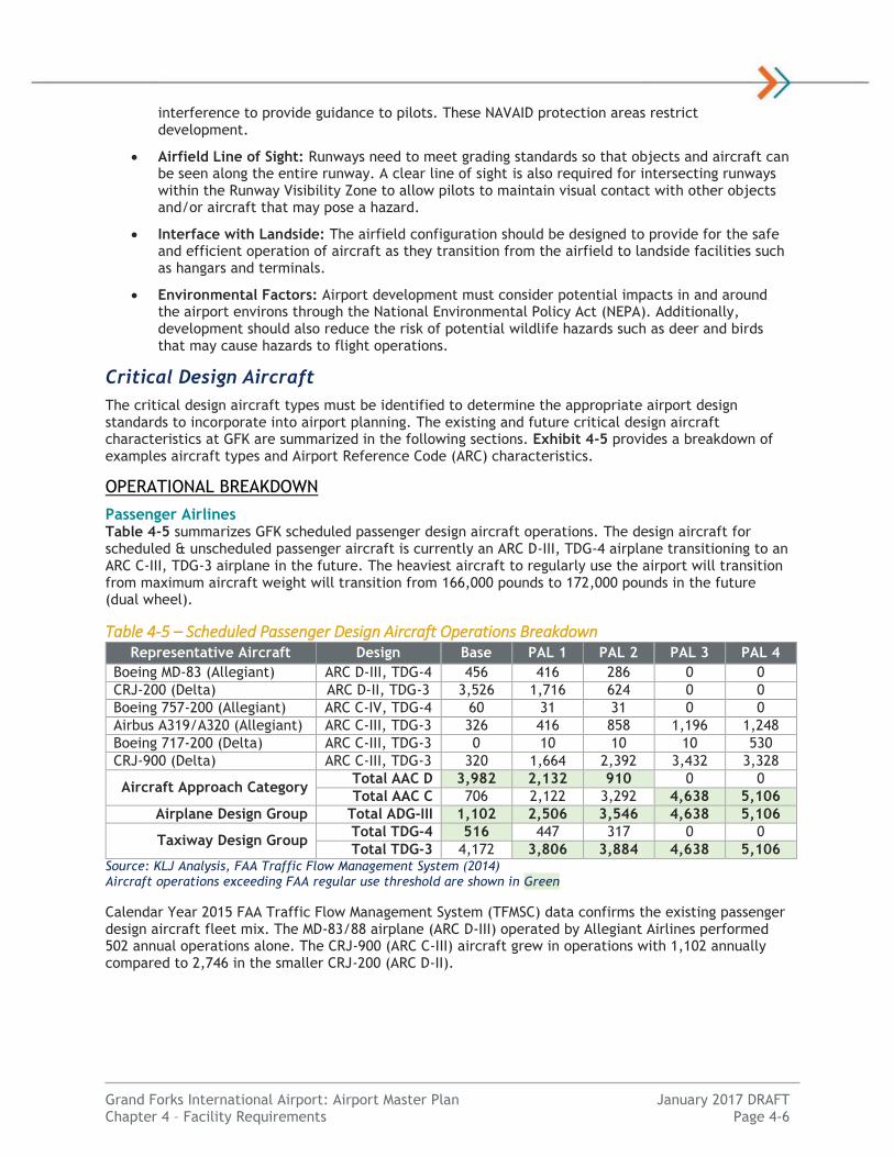
Table 4-18 – Additional Capture Meteorological Analysis
Runway End
Approach Type
Proposed Minimums
Additional Capture
Additional Capture
Wind Coverage*
Net Additional Capture
Net Additional
Utility
35L PA (CAT-II) 100 feet, 1200 RVR 0.71% 69.23% 0.49% 52.1%
17R PA (CAT-I) 200 feet, ½ mile 1.09% 35.34% 0.38% 19.0%
9L APV 250 feet, ¾ mile 0.38% 30.69% 0.12% 6.3%
17R APV 250 feet, ¾ mile 0.38% 25.83% 0.10% 4.8%
27R APV 250 feet, ¾ mile 0.38% 11.72% 0.04% 2.7% Source: National Climatic Data Center data from GFK ASOS (2005-2014; hourly), KLJ Analysis RVR = Runway Visual Range, n.m. = statute miles (reported), APV = Approach with Vertical Guidance, PA = Precision Approach *Wind coverage by runway end only using maximum crosswind components per FAA AC 150/5300-13A.
Lowering approach minimums for Runway 35L to a CAT-II ILS would have the most net benefit by providing an additional 52.1% of additional utility or 43 total additional hours per year (2 days). This could reduce the inaccessibility of the airport by half. A CAT-II ILS system is difficult to justify for FAA funding as a stand-alone project. An interim improvement of lowering visibility minimum to 1800 RVR (3/8 mile) is possible by installing in-pavement runway lighting however.
Lower minimums on Runway 17R to 200-foot cloud ceiling and ½ mile visibility (precision approach) would provide 19.0% of additional airport utility or 33 total hours per year. It is recommended the airport pursue lower approach minimums on Runway 17R through GPS technology and the establishment of an approach lighting system. GPS currently can provide minimums nearly equivalent to CAT-I precision approaches. Further coordination with FAA is required to conduct a feasibility study for the lowest weather minimums to runway ends.
Significant infrastructure improvements to lower instrument approach minimums to other runway ends is not recommended because of the low additional net utility.
Lowering approach weather minimums however requires additional airfield infrastructure and safety areas of varying degrees. It is recommended GFK explore the following approach procedure enhancements:
Accommodate a future GPS precision approach (1/2 mile) to Runway 17R.
Plan to accommodate CAT-II ILS approach (1600 RVR, 1/4 mile) to Runway 35L ultimately with an interim improvement to 1800 RVR.
Upgrade all runway ends to achieve the lowest minimums without substantial improvements or airfield design impacts. Coordinate with FAA Flight Procedures Office.
Infrastructure and navigational aid standards for improvements are outlined further in this chapter. Options for improvements will be evaluated in Chapter 5: Alternatives Analysis.
Temperature Average high temperature data for the hottest month was reviewed from climate data available from the NCDC for GFK. Using locally available data from Grand Forks, the average high temperature in the hottest month from 2006-2015 was 82.6 degrees Fahrenheit. On average there are 9.5 days per year where the high temperature is at or above 90 degrees. This NCDC data from 1981-2012 indicates the average high temperature in July to be 81.0 degrees Fahrenheit. Temperature affects recommended runway lengths.
Airfield Capacity
A master planning-level airfield capacity analysis was completed using the methods outlined in FAA AC 150/5060-5, Airport Capacity and Delay and Airport Cooperative Research Program (ACRP) Report 79:

Grand Forks International Airport: Airport Master Plan January 2017 DRAFT Chapter 4 – Facility Requirements Page 4-16
Evaluating Airport Capacity. Due to the unique operations at GFK and the increased activity, an update review was completed using the Spreadsheet Capacity Model available from ACRP Report 79.
GFK was identified as one of 48 airports in an FAA Study, FACT3: Airport Capacity Needs in the National Airspace System (January 2015). This study identified GFK with a substantial level of traffic that can affect airspace and air traffic. Further evaluation is needed to determine capacity levels at GFK.
FAA has historically defined total capacity of the airfield as the measure of the maximum number of annual aircraft arrivals and departures capable of being accommodated for a runway and taxiway configuration. Delay occurs when operations exceed the available capacity at an airport. Airports should plan to provide capacity enhancements well in advance to avoid unacceptable operational delays.
Airfield capacity is measured using various metrics as defined by FAA:
Hourly Capacity: The maximum number of aircraft operations that can take place on a runway system with a specific runway use configuration in a 1-hour period.
Annual Service Volume (ASV): The reasonable (practical) estimate of an airport’s annual capacity accounting for differences in runway use, aircraft mix, weather conditions, etc. that would be encountered over a year’s time.
Delay: The added trip time attributable to congestion at the study airport, where congestion constitutes any impediment to the free flow of aircraft and/or people through the system.
Annual capacity estimates determine the number of operations at which new airfield infrastructure
would be needed to accommodate demand.
INPUT FACTORS
Aircraft Fleet Mix Different types of aircraft operating on an airport impacts airport capacity. In addition to required arrival and departure flow separation requirements between similar aircraft types, aircraft with different speeds require additional spacing requirements to maintain minimum separation. Greater spacing is also required for small aircraft to avoid wake turbulence created by larger aircraft. The airport’s fleet mix index is established using guidelines established in ACRP Report 79 identified in Table 4-19.
Table 4-19 – Aircraft Fleet Mix Classifications Aircraft Classification Characteristics
Small - S Less than 12,500 lbs. (Single Engine)
Small - T Less than 12,500 lbs. (Twin Engine)
Small + Corporate airplanes between 12,500 lbs. and 41,000 lbs.
Large - TP Turboprop between 12,500 lbs. and 255,000 lbs.
Large - Jet Jet between 41,000 lbs. and 300,000 lbs.
Large - 757 Boeing 757 series
Heavy More than 300,000 lbs. Source: ACRP Report 79
The aircraft fleet mix percentage for capacity calculations is based on the aviation activity forecasts. Overall fleet mix assumptions for GFK are summarized in Table 4-20.

Grand Forks International Airport: Airport Master Plan January 2017 DRAFT Chapter 4 – Facility Requirements Page 4-17
Table 4-20 – Aircraft Fleet Mix Assumptions
Aircraft Classification Base PAL 4 PAL 4
High Forecast
Small - S 80.1% 81.7% 82.0%
Small - T 16.6% 15.8% 15.7%
Small + 1.5% 1.0% 0.9%
Large - TP 0.0% 0.0% 0.0%
Large - Jet 1.5% 1.2% 1.1%
Large - 757 0.1% 0.4% 0.3%
Heavy 0.2% 0.0% 0.0%
Total Annual Operations 324,196 350,477 383,247 Source: ACRP Report 79, KLJ Analysis
Differing GFK runway fleet mix calculations were used in this analytical analysis. In general, primary Runway 17R-35L is capable of accommodating all fleet mix types. Secondary Runway 9L-27R is capable of accommodating aircraft identified as “small” according to the ACRP definitions, and the remaining runways are used for small single-engine and multi-engine aircraft up to 12,500 pounds exclusively.
Meteorological Conditions GFK meteorological data was analyzed to determine how often the airfield is operational. This affects the overall capacity of the airfield as runway fleet mix and hourly are affected by the prevailing weather. Conditions are split into VMC, IMC and periods when the airport is unusable due to weather below minimums. As shown in Table 4-21, the vast majority of flight operations are conducted in VMC.
Table 4-21 – Airport Meteorological Conditions Weather Condition Percent of Year
Visual Meteorological Conditions (VMC) 91.71%
Instrument Meteorological Conditions (IMC) 7.34%
Below IMC (Closed) 0.95% Source: National Climatic Data Center data from GFK ASOS (2005-2014; hourly), KLJ Analysis
Runway Use The runway use configuration affects the operational efficiency and capacity of an airfield. An independent runway is one that can be operational and not affect arrivals and/or departures from other runways. A dependent runway is directly affected by the operations of another runway. Operations from another runway must be clear so operations on the other runway can safely occur. A dependent runway configuration increases wait time, reduces capacity and can increase overall delay.
At GFK, each airfield traffic flow pattern has a set of two independent runways that remain operational for small aircraft. Each has an opposite-direction rectangular traffic patterns to avoid airspace overlap. Primary Runway 17R-35L is the only runway that can consistently accommodate large aircraft because of its length. Because Runway 17R-35L and secondary Runway 9L-27R intersect, all east-west runway operations must cease when Runway 17R-35L is in use by large aircraft. Delays are extended to mitigate the effects of wake turbulence created by the departure of the larger aircraft.
The maximum crosswind component for small aircraft (ARC A-I/B-I) is 10.5 knots. Local ATCT prefers to use a north-south flow pattern with an east-west flow only used during stronger crosswind conditions to minimize the safety risks. FAA standards are used as a basis for this study. Exhibits 4-22 and 4-23 depict the runway usage and capacity based on existing airfield configuration and meteorological conditions.

Grand Forks International Airport: Airport Master Plan January 2017 DRAFT Chapter 4 – Facility Requirements Page 4-18
Exhibit 4-22 – VMC Runway Utilization
RWY Condition Aircraft Types Touch & Go
Crossing Delays
% of Time
Hourly
Capacity
ASV
Graphic
North Flow
35L VMC All 0.0% No 43.69% 67
219,600
35R VMC Small – S Small - T
0.0% No 43.69% 67
219,600
South Flow
17L VMC Small – S Small - T
0.0% No 41.39% 67
219,600
17R VMC All 0.0% No 41.39% 67
219,600
East Flow
9L
35L or
17R
VMC Small (9L)
All (17R or 35L)
0.0%
0.0% Yes 1.62%
56
183,600
9R VMC
Small – S Small - T
0.0% Yes 1.62% 54
177,000
West Flow
27R
35L or
17R
VMC Small (27R)
All (17R or 35L)
0.0%
0.0% Yes 5.01%
56
203,300
27L VMC Small – S Small - T
0.0% Yes 5.01% 54
177,000
Source: National Climatic Data Center data from GFK ASOS (2005-2014; hourly), ACRP Report 79 Spreadsheet Capacity Model, KLJ Analysis
Legend: Large Aircraft Flow Small Aircraft Flow

Grand Forks International Airport: Airport Master Plan January 2017 DRAFT Chapter 4 – Facility Requirements Page 4-19
Exhibit 4-23 – IMC Runway Utilization
RWY Condition Aircraft Types
Crossing Delays
Utilization
Hourly
Capacity
ASV
Graphic
North Flow
35L IMC All No 4.41%
39
127,800
South Flow
17R IMC All No 2.37% 39
127,800
East Flow
9L
35L or
17R
IMC Small (9L)
All (17R/35L) Yes 0.23%
34
111,500
West Flow
27R
35L or
17R
IMC Small (27R)
All (17R/35L) Yes 0.33%
34
111,500
Closed (Below IMC Minimums)
All Closed All No 0.95% 0 N/A
Source: National Climatic Data Center data from GFK ASOS (2005-2014; hourly), ACRP Report 79 Spreadsheet Capacity Model, KLJ Analysis
Legend: Large Aircraft Flow Small Aircraft Flow

Grand Forks International Airport: Airport Master Plan January 2017 DRAFT Chapter 4 – Facility Requirements Page 4-20
Based on weather observations and local operational patterns, it is assumed a north-south traffic flow scenario occurs 91.86 percent of the time. An east-west flow is preferred 7.19 percent of the time during periods when crosswinds exceed the FAA standard component of 10.5 knots for small aircraft.
Other Modeling Considerations The airport has an operating ATCT which can safely direct traffic to maximize capacity. Each runway has a full-parallel taxiway and a sufficient number and location of exit taxiways to allow aircraft to expediently leave the runway environment upon landing. No adjustment factor was used to reduce capacity as a result of this infrastructure.
“Touch-and-go” operations are those that land, keep rolling, then takeoff on the same runway without exiting the runway. These typically occur with small training aircraft and counts for two operations, thus increasing airfield capacity. UND Aerospace flight training operations does not conduct “touch-and-go” operations. These training flights conduct “stop-and-go” operations that require an aircraft to come to a complete stop on the runway before commencing their departure roll. These operations do not decrease runway occupancy time.
GFK Airport Traffic Control Tower (ATCT) staff conducted a runway occupancy analysis during a north-south flow day in July 2016. The average recorded results are as follows:
UND Single-Engine Aircraft: 47 seconds “stop-and-go”, 54 seconds full-stop landing
UND Multi-Engine Aircraft: 47 seconds “stop-and-go”, 52 seconds full-stop landing
Turboprop Aircraft: 50 seconds full-stop landing
Regional Jet and Narrowbody Aircraft: 53 seconds full-stop landing
Heavy Aircraft: 74 seconds full-stop landing
The above runway occupancy time factors are used for the ACRP Report 79 Spreadsheet Capacity Model. In this study, a 15 percent “touch-and-go” factor is added in an attempt to model the reduction in runway occupancy time for “stop-and-go” operations.
Arrivals are assumed to be 50 percent of total operations for a balanced airfield. Based on input from local ATCT staff, runway crossing delays occur 2 times during the peak hour when the airport was in an east-west flow. The average total crossing delay was assumed to be five minutes each time to allow wake turbulence to dissipate. Other factors such as the length of a common approach and aircraft separation distances were reviewed by local ATCT staff.
Annual service volume was estimated based on ACRP methodology using unique existing demand inputs from GFK, including daily (281.6) and hourly (11.6) demand ratios. Other aircraft-to-aircraft separation distance adjustments were made in coordination with GFK ATCT. All other standard assumptions were used from the ACRP Report 79 Spreadsheet Capacity Model.
HOURLY CAPACITY
Using the factors described above, the hourly capacity is calculated for different airfield operational scenarios using the guidance in ACRP Report 79. A summary of the calculated hourly capacity figures is shown in Exhibit 4-24.
The calculated current design hourly volume exceeds the available capacity for each individual runway scenario. Absolute peak hourly operations were achieved on March 20, 2012 with 220 operations. Individual peaks can occur in situations where high-capacity factors occur such as a consistent small aircraft fleet mix, higher percentages of departures, expanded airport traffic patterns, closer aircraft spacing or familiarity with local ATC procedures.
Capacity is reduced during the east-west flow because of the occasional large aircraft traffic on the primary runway causing crossing delays. IMC capacity is limited to two runways. IMC capacity is also reduced due to the wider fleet mix range and additional aircraft spacing requirements. The vast majority of demand is seen during VMC.
The forecasted change in fleet mix does not have a significant effect on total hourly capacity.

Grand Forks International Airport: Airport Master Plan January 2017 DRAFT Chapter 4 – Facility Requirements Page 4-21
Exhibit 4-24 – Runway Hourly Capacity
Source: National Climatic Data Center data from GFK ASOS (2005-2014; hourly), ACRP Report 79 Spreadsheet Capacity Model, KLJ Analysis IMC = Instrument Meteorological Conditions, VMC = Visual Meteorological Conditions
ANNUAL SERVICE VOLUME
Annual Service Volume (ASV) is the estimate of the airport’s annual capacity to accommodate aircraft operations considering the variations in a demand. ASV is intended to identify a threshold to which additional aircraft operations would result in a disproportionate increase in average aircraft delays.
ASV is calculated based on the weighted hourly capacity multiplied by hourly and daily demand ratios. The ratio of the total operations to an airport’s ASV determines if and when an airport should plan for capacity improvements to increase overall capacity. Table 4-25 summarizes the calculations at GFK.
Table 4-25 – Annual Service Volume (ASV)
Metric 2008 Base (2014) PAL 4
Constrained PAL 4
Unconstrained
Annual Operations 230,220 324,196 350,477 383,248
Annual Service Volume 341,250* 407,557 407,557 407,557
Overall Capacity Level 67.6% 79.6% 86.0% 94.0% Source: FAA AC 150/5060-5, Airport Capacity and Delay, ACRP Report 79, KLJ Analysis *Calculated per 2008 Airport Master Plan prior to Runway 9R-27L construction
The existing airport has reached 79 percent of its overall airfield capacity. In Fiscal Year 2012, GFK recorded 372,012 operations which was over 91 percent of overall airfield capacity. The east-west flow VMC flow pattern alone currently operates at nearly 90 percent of total capacity.
FAA Order 5090.3C, Field Formulation of the NPIAS recommends airports plan for capacity development such as a new runway once capacity levels have reached 60 to 75 percent of annual capacity. Typically, airports plan for capacity enhancement projects at 60 percent of its annual capacity with implementation or demand management strategies occurring at 80 percent.
134 134
110 110
39 39 34 34
0
124
0
50
100
150
200
250
VMC North(43.7%)
VMC South(41.4%)
VMC East(1.6%)
VMC West(5.0%)
IMC North(4.4%)
IMC South(2.4%)
IMC East(0.2%)
IMC West(0.3%)
Closed(1.0%)
WeightedHourly
Capacity
Opera
tions
per
Hour
Airport Flow Pattern
Runway Hourly Capacity
Calculated Hourly Capacity Absolute Peak Hour
PAL 4 Design Hour PAL 4 Unconstrained Design Hour
Base Design Hour

Grand Forks International Airport: Airport Master Plan January 2017 DRAFT Chapter 4 – Facility Requirements Page 4-22
The lack of available GFK operational capacity (ground infrastructure and available airspace) and a subsequent increase in flight delays has led UND Aerospace to limit total annual flight training hours for safety and efficiency. Flight training students are very sensitive to unproductive delays as they increase the student’s per flight cost. GFK should take steps to engage UND Aerospace to discuss airfield capacity restrictions and if solutions are needed.
AIRCRAFT DELAY
Aircraft delay exists because of the sheer volume of traffic at GFK and limitations to total throughput to maintain safety standards. Delay is measured in minutes per aircraft and hours per year. The FAA’s assumptions identified in FAA AC 150/5060-5, Airport Capacity and Delay are used to develop delay measures and identify cost. In general, as the demand approaches ASV capacity so does delay.
Airfield Infrastructure
The runway/taxiway configuration provides capacity and limitations to the total number of takeoffs and landings. Limitations can create delays. FAA AC 150/5070-6B, Airport Master Plans identifies 4 to 6 minutes of annual average delay as an airport approaching practical capacity and is generally considered congested. Average delays for all flow patterns are summarized in Table 4-26. The highest existing delay occurs when in the east-west VMC flow pattern where calculated delays currently range between 0.6 and 2.1 minutes per aircraft (90% ASV).
Table 4-26 – Aircraft Delay
Factors Base PAL 4
Constrained PAL 4
Unconstrained
Capacity Level 79.6% 86.0% 94.0%
Single Aircraft Delay (Minutes)
Avg. Aircraft Delay Range 0.4 -> 1.5 0.5 -> 1.9 0.9 -> 2.5
Average Aircraft Delay 0.9 1.3 1.7
Annual Delay (1,000s Minutes)
Average Aircraft Delays 351 456 652
Annual Delay Cost (2015 dollars)
Average Aircraft Delays $1,507,000 $1,960,000 $2,773,000 Source: FAA AC 150/5060-5, Airport Capacity and Delay, KLJ Analysis
Without airfield capacity improvements, overall peak average delays in the future are calculated to approach 2.5 minutes per aircraft in an unconstrained traffic scenario. When GFK is operating in an east-west flow with reduced capacity, peak average delays increase to 5.5 minutes per aircraft in an unconstrained traffic scenario (106% ASV).

Grand Forks International Airport: Airport Master Plan January 2017 DRAFT Chapter 4 – Facility Requirements Page 4-23
Airspace
Additional delays occur as a result of airspace limitations within the airport traffic pattern. The traffic pattern is a rectangular aircraft sequence around a runway to perform takeoffs and landings. Aircraft require minimum separation distances; these increase for different aircraft types and larger/faster aircraft. When the traffic pattern becomes congested with airplanes, aircraft are asked to extend their traffic pattern to accommodate more aircraft. This requires more flying time. Both of these factors result in individual airplane delays. Airspace delays occur even though the runway may be operating at peak efficient operational capacity for total takeoffs and landings.
FAA Order 7400.2, Procedures for Handling Airspace Matters describes traffic pattern airspace as 4 aircraft of the same category. A typical traffic pattern on Runway 17L/35R in a Category A small aircraft involves flying approximately 5 nautical miles and takes an average flying time of less than 5 minutes1 outside of the immediate runway environment. Aircraft average 6 circuits per hour. There may be as many as 8 aircraft in the pattern at one time during peak periods. This results in the same number of takeoffs and landings but additional delays per aircraft. According to FAA airspace standards, each additional aircraft in the traffic pattern requires an additional 0.75 miles of airspace. Additional flying time (delays) per traffic pattern circuit can then be estimated.
SCENARIO ANALYSIS
Airfield Infrastructure This section reviews various airfield improvements and their effect on total airfield capacity. Options include:
Option #1: Utilize a 13-knot crosswind component. This operational improvement has already been implemented by local ATCT to keep independent operations on north-south runways as long as practical to enhance safety. The improvement also results in a small increase in total airfield capacity. This method is utilized for subsequent options.
Option #2: Extend Runway 9L/27R to accommodate regular use of large aircraft. This improvement would allow for independent operations on east-west runways, decreasing the PAL 4 unconstrained average delays for this VMC traffic flow pattern. Overall airfield capacity would marginally improve.
Option #3: Implement operational procedural changes. Replace stop-and-go with touch-and-go operations and utilize 13-knot crosswind component. This would reduce runway occupancy time and increase capacity. Spreading out flight schedules throughout the day would also reduce the peak hour.
Option #4: Construct a capacity-driven north-south runway. This improvement would result in a significant increase in total airfield capacity as this flow pattern is utilized nearly 97 percent of the time in VMC. It would allow for three independent runways; two for VFR small aircraft one for IFR and large aircraft primarily.
Exhibit 4-27 summarizes the characteristics of each scenario.
1 Does not include time on the runway. Assumes an average flying speed of 70 knots in Category A aircraft.
FAA Traffic Pattern Airspace

Grand Forks International Airport: Airport Master Plan January 2017 DRAFT Chapter 4 – Facility Requirements Page 4-24
Exhibit 4-27 – Scenario Analysis Metric Base PAL 4+ Opt. #1 Opt. #2 Opt. #3 Opt. #4
Annual Operations 324,196 383,248 383,248 383,248 383,248 383,248
Annual Service Volume 407,557 407,557 409,819 412,180 493,031 589,582
Overall Capacity Level 79.6% 94.0% 93.5% 93.0% 77.7% 65.0%
North-South Flow Peak Delay 0.7 min. 1.9 min. 1.9 min. 1.9 min. 1.1 min. 0.7 min.
East-West Flow Peak Delay 2.1 min. 5.5 min. 5.5 min. 1.9 min. 1.9 min. 2.8 min. Source: FAA AC 150/5060-5, Airport Capacity and Delay, ACRP Report 79, KLJ Analysis
When operations reach 370,000 annually, peak east-west runway flow pattern delays eclipse 4 minutes per aircraft. Option #4 provides the most additional capacity followed by Option #3.
Airspace
A significant portion of GFK aircraft operations involve flight training work in the immediate GFK traffic pattern. Because of this, additional consideration must be made for delays associated with the surrounding airspace.
Exhibit 4-28 summarizes airspace delays resulting from certain traffic pattern (circuit) scenarios assuming they occur an average of 8 hours per day at a cost of $200 per flight hour.
Exhibit 4-28 – Traffic Pattern Aircraft Delay Factors Standard Busy Congested
Total Aircraft in Traffic Pattern At One Time 4 6 8
Airspace Delay Per Aircraft In Circuit 0 minutes 2.6 minutes 5.2 minutes
Delay Per Aircraft Operation for Large Aircraft2 0.4 minutes 0.6 minutes 0.8 minutes
Total Additional Time Per Aircraft for 6 Circuits 4 minutes 22 minutes 40 minutes
Average Annual Aircraft Delays (1,000s of Minutes) 12 65 117
Average Annual Aircraft Delay Costs $166,000 $1,301,000 $3,316,000 Source: FAA Order 7400.2, Procedures for Handling Airspace Matters, KLJ Analysis
Total airfield infrastructure and airspace delays combined during peak periods approach 3 minutes per aircraft operation when the traffic pattern is congested. Cumulative airspace doubles the time to complete a single traffic pattern circuit. This is considered unacceptable delays and increased costs for flight training aircraft. The calculation includes a 5 minute per aircraft average delay when the traffic pattern is interrupted by a large aircraft operation, which occurs approximately twice every peak hour.
Strategies to relieve excessive traffic pattern delays include reducing runway occupancy time or constructing an additional runway that can be dedicated to traffic pattern operations.
Option #1: Implement operational enhancements to reduce runway occupancy time. One option is to allow touch-and-go operations. A 50 percent touch-and-go percentage would increase VMC hourly runway capacity by nearly 30 percent (67 -> 87) over the existing condition according to ACRP Report 79 Spreadsheet Capacity Model. This would allow more aircraft to be in the traffic pattern without expanding the pattern size significantly.
Option #2: Implement capacity infrastructure enhancements. Construct an additional north-south runway exclusively used for small aircraft traffic pattern work. This would allow Runway 17R/35L to be dedicated for straight-in/out large aircraft and IFR operations without affecting the traffic pattern airspace in a north-south flow. Some additional taxi time would be required for each trip.
Any operational changes to allow touch-and-go operations or adjust flight schedules would have to be approved and implemented by UND Aerospace. Currently touch-and-go operations are not authorized.
2 Large aircraft delays currently occur on Runway 17L/35R and 9L/27R only due to concurrent or crossing aircraft operations.

Grand Forks International Airport: Airport Master Plan January 2017 DRAFT Chapter 4 – Facility Requirements Page 4-25
Providing two dedicated GA training runways in a north-south flow pattern would reduce delays by over 3 minutes per aircraft hour at a minimum at unconstrained capacity levels. It would also free up additional airspace to conduct simultaneous uninterrupted traffic pattern operations in similar class aircraft, reducing the need to expand the traffic pattern size as often.
SUMMARY
The purpose of this review is to provide a master planning-level review of airport capacity for long-range planning. Exhibit 4-29 graphically summarizes the capacity analysis.
Total airfield capacity improvements to improve overall airfield capacity should be planned now and implemented as soon as possible as the current Annual Service Volume is near 80 percent. UND Aerospace has already restricted capacity to reduce flight training delays.
Exhibit 4-29 – Airfield Capacity Summary
Source: KLJ Analysis
Improvements to consider to reduce total delays include operational changes such as implementing touch-and-go operations and allowing 13-knot crosswind operations in the north-south flow. Infrastructure changes include but are not limited to extending Runway 9L/27R to reduce crossing delays and constructing a new north-south runway for exclusive traffic pattern operations. Both improvements would reduce delays caused by large aircraft crossings.
Runways
GFK has four (4) runways. Runway 17R/35L is the airport’s primary runway and currently serves all of GFK’s air carrier traffic. Both Runway 17R/35L and 9L/27R are maintained by the airport to FAR Part 139 standards.
Runway 17R/35L: GFK’s primary runway is 7,351 feet long and 150 feet wide. This runway is currently designed to accommodate precision instrument approaches and aircraft weights up to 270,000 pounds dual-tandem wheel. The runway pavement is in good condition with its last major rehabilitation in 2001. This runway is equipped with High Intensity Runway Lighting (HIRL), and has precision pavement markings.
Runway 9L/27R: GFK’s crosswind runway is 4,206 feet long and 100 feet wide. This runway is currently designed to accommodate non-precision instrument approaches with vertical guidance and aircraft weights up to 55,000 pounds dual-wheel. This pavement condition is in very good condition. This
0
100,000
200,000
300,000
400,000
500,000
600,000
700,000
Base PAL 1 PAL 2 PAL 3 PAL 4 PAL 4 High
Annual Flight
Opera
tions
Planning Activity Level (PAL)
Airfield Capacity Summary
UND Flight Operations Other Flight Operations
60% ASV 80% ASV
100% ASV
Implement Capacity Improvements

Grand Forks International Airport: Airport Master Plan January 2017 DRAFT Chapter 4 – Facility Requirements Page 4-26
runway is equipped with Medium Intensity Runway Lighting (MIRL), and has non-precision pavement markings.
The other two runways (17L/35R and 9R/27L) are used exclusively for small general aviation traffic, primarily for University of North Dakota flight training operations.
Runway 17L/35R: This general aviation runway is 3,901 feet long and 75 feet wide. This runway is currently designed to accommodate visual approaches and aircraft weights not exceeding 12,500 pounds. The runway’s pavement is in good condition. Last major reconstruction/rehabilitation took place in 1988. This runway is equipped with Medium Intensity Runway Lighting (MIRL) and has visual pavement markings.
Runway 9R/27L: This general aviation crosswind runway is 3,300 feet long and 60 feet wide. This runway is currently designed to accommodate visual approaches and aircraft weights not exceeding 12,500 pounds. The runway’s pavement is in very good condition and was constructed in 2009. This runway is equipped with Medium Intensity Runway Lighting (MIRL) and has visual pavement markings.
Helipads (H1 – H12): Twelve (12) helipads were designated as official landing areas in 2015. Each helipad has dimensions of 60 feet by 60 feet and is a turf surface. Helipads are located on the east quadrant of the airport and depicted on the Airport Layout Plan (ALP), primarily used for helicopter flight training activity.
RUNWAY DESIGN CODE
Per FAA design standards, the design aircraft and instrument approach minimums dictate Runway Design Code (RDC) standards for each runway end in both the existing and future planned elements. The RDC helps drive the framework for identifying any existing deficiencies and assists the airport in planning for future projects. Based on FAA AC 150/5300-13A, individual RDCs are assigned to each runway end.
Runway 17R/35L: The existing RDC for Runway 17R is D-IV-5000 (not lower than 1 mile) and Runway 35L is D-IV-2400 (½ mile). The recommended future RDC code for Runway 17R is C-III-4000 (not less than ¾ mile) and 35L’s recommended future RDC is C-III-1200 (not lower than ¼ mile). Factors involving the recommended changes include the change in design aircraft over time. Runway 17R’s lower visibility minimums (not lower than ¾ mile) are based off a planned enhancement to that runway end. Runway 35L’s lowered approach minimums are based off of an ultimate CAT-II precision approach.
Runway 17L/35R: The existing RDC is B-II(Small)-VIS for both runway ends. Recommended future RDC for both runway ends is B-II(Small)-5000 (Not lower than 1 mile). It is not anticipated Runway 17L/35R will need to accommodate larger or heavier aircraft greater than 12,500 pounds in the future. However, planning for RNAV (GPS) approaches for both runway ends with vertical guidance will increase usability of the runway and provide flexibility of runway utilization during IMC. Runway 17L/35R and 17R/35L have a centerline separation distance to provide independent instrument approaches and radar departures. This improvement will provide added benefit for those users located on the east side of the airport.
Runway 9L/27R: The existing RDC is B-II-5000 (not lower than 1 mile) for both runway ends. Recommended future RDC is C-III-5000 (not lower than 1 mile) for the Runway 27R end, and C-III-4000 for the Runway 9L end to increase utility to accommodate lower instrument approach minimums. Reasoning behind the increase in AAC and ADG is behind the ultimate use of Runway 9L/27R for air carrier traffic.
Runway 9R/27L: The existing RDC is B-I(Small)-VIS for both runway ends. Recommended future RDC for both runway ends is to remain B-I(Small)-VIS for both runway ends. It is not anticipated Runway 9R/27L will need to accommodate instrument approaches, larger or heavier aircraft in the future.

Grand Forks International Airport: Airport Master Plan January 2017 DRAFT Chapter 4 – Facility Requirements Page 4-27
RUNWAY REFERENCE CODES
Runway Reference Codes (RRCs) indicate current operational capabilities where no special operations procedures are necessary, and without consideration of the actual runway length. The existing operational capabilities of the runway is identified based on a taxiway separation distance. Runway Reference Codes (RRCs) include an Approach Reference Code (APRC) and Departure Reference Code (DPRC). Also multiple codes are possible for each runway end with an APRC.
At GFK, the current runway to parallel taxiway separation distance is 400 feet for all runways. The runway and taxiway infrastructure does not limit existing, future or ultimate RDC classifications at GFK.
Runway 17R/35L: The existing APRCs for Runway 17R are D-IV-5000 and D-V-5000 (not lower than 1 mile). Runway 35L’s existing APRC codes are D-IV-2400 and D-V-2400 (not lower than ½ mile). The existing DPRCs are D-IV and D-V for both runway ends. Future APRCs for Runway 17R are D-IV-4000 and D-V-4000 (not lower than ¾ mile). Runway 35L’s future APRC codes are D-IV-1600 (not lower than ¼ mile) and D-V-2400 (not lower than ½ mile). Future DPRC codes remain the same (D-IV and D-V).
Runway 17L/35R: Existing APRCs for both Runway 17L and 35R are D-IV-VIS and D-V-VIS. The existing DPRCs are D-IV and D-V for both runway ends. Future APRCs for both Runway 17R and 35L are D-IV-5000 and D-V-5000 (not lower than 1 mile). Future DPRC codes for both Runway 17R and 35L are D-IV and D-V.
Runway 9L/27R: The existing APRCs for both runway ends are D-IV-5000 and D-V-5000 (not lower than 1 mile). Existing DPRCs are D-IV and D-V for both runway ends. Future APRC and DPRC codes remain the same in the future.
Runway 9R/27L: Existing APRCs for both 9R and 27L are D-IV-VIS and D-V-VIS. The existing DPRCs are D-IV and D-V for both runway ends. Future APRCs for both Runway 9R and 27L are D-IV-VIS and D-V-VIS. Future DPRC codes for both runway ends are D-IV and D-V.
DESIGN STANDARDS
Basic Safety Standards One primary purpose of this master plan is to review and achieve compliance with all FAA safety and design standards. The design standards vary based on the RDC and RRC as established by the design aircraft. In addition to the runway pavement width, some of the safety standards include:
Runway Safety Area (RSA): A defined graded surface surrounding the runway prepared or suitable for reducing the risk of damage to aircraft in the event of an undershoot, overshoot or excursion from the runway. The RSA must be free of objects, except those required to be located in the RSA to serve their function. The RSA should also be capable to supporting airport equipment and the occasional passage of aircraft.
Runway Object Free Area (ROFA): An area centered on the ground on a runway provided to enhance the safety of aircraft operations by remaining clear of objects, except for objects that need to be located in the OFA for air navigation or aircraft ground maneuvering purposes.
Runway Obstacle Free Zone (ROFZ): The OFZ is the three-dimensional volume of airspace along the runway and extended runway centerline that is required to be clear of taxiing or parked aircraft as well as other obstacles that do not need to be within the OFZ to function. The purpose of the OFZ is for protection of aircraft landing or taking off from the runway and for missed approaches.
Other basic design standards include runway surface gradient, runway shoulder width to prevent soil erosion or debris ingestion for jet engines, blast pad to prevent soil erosion from jet blast, and required separation distances to markings, objects and other infrastructure for safety. Critical areas associated with navigational aids as well as airspace requirements are described further in this chapter.

Grand Forks International Airport: Airport Master Plan January 2017 DRAFT Chapter 4 – Facility Requirements Page 4-28
Other Design Standards Runways must meet line-of-sight requirements. Along individual runways, a point 5 feet above the runway must be mutually visible with any other point 5 feet above the runway centerline. For intersecting runways, Runway Visibility Zone (RVZ) standards require a clear visible 5-foot high line-of-sight to enhance safety amongst airport users when runways intersect. This is applicable at GFK as Runway 17R/35R and Runway 9L/27R intersect. Portions of the old air carrier apron are located in the RVZ.
Runway Configuration Runway 17R/35L and 17L/35R are parallel north-south runways with runway centerline separation distance of 3,680 feet. Runway 9R/27L and 9L/27R are parallel east-west runways and have a separation distance of 5,200 feet. Runway 17R/35L and 9L/27R are intersecting runways.
A minimum separation distance of 700 feet is needed for visual operations. Simultaneous radar departures require a distance of at least 3,500 feet. Simultaneous approaches (non-precision) require a minimum separation distance of 2,500 feet when runway thresholds are not staggered.
The Grand Forks Air Traffic Control Tower (ATCT) identified systemic safety issues associated with Runway 9L/27R. In a memorandum prepared October 22, 2015 (see Appendix X), the GFK ATCT Local Safety Council provided GFK Airport Management with an outline of the concerns:
GFK has one of the highest volumes of training students and traffic volumes in the nation.
A north-south traffic runway configurations allow GFK ATCT to work an optimal flow of traffic.
When weather conditions dictate otherwise, an east-west traffic flow is utilized.
The dimensions of the east-west runways limit operations to mainly small aircraft.
Larger aircraft including business jets, passenger carrying air taxi aircraft and air carriers require the use of Runway 17R/35L.
The use of Runway 17R/35L during an east-west traffic flow creates an intersecting runway, converging traffic patterns, and converging non-intersecting runway operations.
Most simultaneous independent operations are no longer permitted with non-intersecting converging runways at GFK, requiring more ATCT effort to achieve required aircraft spacing for east-west traffic flow operations.
The large volume of flight training traffic increases complexity of east-west traffic flow configurations resulting in the loss of pilot situational awareness, creating a rushed atmosphere for inexperienced pilots, increasing delays and creating wake turbulence concerns.
A near mid-air collision occurred in May 2015 in a west traffic configuration.
The GFK ATCT Local Safety Council is requesting “serious consideration and timely action” for the reconstruction of Runway 9L/27R to accommodate larger aircraft, including air carrier aircraft. Upgrading Runway 9L/27R is crucial in mitigating the safety risks and complexity present at GFK during east-west traffic flow configuration. Once completed, converging runway operations will no longer be necessary at GFK.
LAND USE CONTROL
Runway Protection Zone The Runway Protection Zone (RPZ) is a trapezoidal land use area at ground level prior to the landing threshold or beyond the runway end. The RPZ’s function is to enhance the protection of people and property on the ground. The RPZ size varies based on the runway’s RDC. The RPZ is further broken down into two types and two areas:
Approach RPZ: Approach RPZ extends from a point 200 feet from the runway threshold.

Grand Forks International Airport: Airport Master Plan January 2017 DRAFT Chapter 4 – Facility Requirements Page 4-29
Departures RPZ: Departure RPZ extends 200 feet from the runway end or claimed Takeoff Runway Available (TORA).
Central Portion: Land within the RPZ centered on runway centerline with a width matching the width of the ROFA.
Controlled Activity Area: Land with the RPZ on the sides of the central portion.
FAA permissible land uses without further evaluation include farming that meets airport design standards, irrigation channels that do not attract wildlife, controlled airport service roads, underground facilities and unstaffed NAVAIDs that are required to be within the RPZ. Airport owners should, at a minimum, maintain the RPZ clear of all facilities supporting incompatible activities. It is desirable to clear all above-ground objects from the RPZ.
Exhibit 4-30 graphically depicts the characteristics of an RPZ.
Exhibit 4-30 – FAA Runway Protection Zone
Source: FAA AC 150/5300-13A, Change 1 (Airport Design)
RPZs and the effort to ensure compatible land use within them are currently a high priority for the FAA. Protection of the RPZ is achieved through airport control over RPZs including fee title ownership or clear zone easement. The increased emphasis has resulted in additional requirements to monitor and analyze RPZs for conformance to established policies and standards.
In September 2012, FAA issued an interim policy on activities within an RPZ providing airports with guidance on land use compatibility standards. The standards from the interim guidance are summarized below:
New or Modified Land Uses: FAA coordination is required for new or modified land uses within the RPZ as a result of an airfield project, change in RPZ dimensions or local development proposal.
Land Uses Requiring FAA Coordination: Building and structures, recreational land uses, transportation facilities (i.e. roads, parking, rail), fuel storage, hazardous material storage, wastewater treatment, above-ground utility infrastructure

Grand Forks International Airport: Airport Master Plan January 2017 DRAFT Chapter 4 – Facility Requirements Page 4-30
Alternatives Analysis: A full range of alternatives must be evaluated prior to FAA coordination that avoid introducing the land use into the RPZ, minimize the impact of the land use in the RPZ and mitigate risk to people and property on the ground.
Existing Land Uses in the RPZ: No change in policy, airports should work with FAA to remove or mitigate the risk of any existing incompatible land uses in the RPZ. Incompatible land uses in the RPZ from previous FAA guidance include but are not limited to residences, places of public assembly (i.e. uses with high concentration of persons), fuel storage facilities and wildlife attractants.
The following roadways and other significant man-made land uses are within the existing approach RPZs at GFK:
Runway 35L: Public east-west road (U.S. Highway 2) is located 2,160 feet from runway threshold and traverses approximately 1,600 feet through the RPZ. In 2013 the Average Daily Traffic count was approximately 10,000 cars per day.
Runway 27L: A storm water drainage-way located 550 feet from runway threshold and traverses 350 feet through the RPZ. Public north-south road (83rd St N) is located 780 feet from runway threshold and traverses approximately 400 feet through the RPZ. Approximately 4 acres of a private auto-parts salvage lot (vehicular parking facility) is also located within the RPZ beginning 800 feet from the runway threshold.
The land uses in the existing RPZs appear to be acceptable at the present time. Further review is required if new land uses, runway end locations or a change in the size of the RPZ is proposed and a land use requiring FAA coordination is in the RPZ.
GFK should consider acquiring land to control all existing, future and ultimate RPZs in fee simple or land use easement.
Land Acquisition According to FAA, off-airport development has a negative impact on current and future airport operations when it creates obstacles to airport design, land use and airspace standards surrounding the airport. Land acquisition allows the airport to protect airspace and land use areas from possible intrusions. Acquiring all land is generally not feasible, and is usually supplemented by local zoning and easements to mitigate potential incompatible land uses and potential obstacle conflicts.
FAA encourages the airport sponsor to own the following land for existing and planned airport configuration:
Airport Infrastructure
Runway and Taxiway Object Free Areas
Runway Protection Zones
Building Restriction Line
Navigational Aid Critical Areas
Airspace Protection
Identified land acquisition areas to help meet current standards include acquiring remaining land use control within the Runway 27L RPZ. Land required for future development will be identified in Chapter 5: Alternatives Analysis.
Airport Zoning FAA recommends airport sponsors protect airport land use and airspace through local zoning. Owners of public airports are encouraged to enact airport overlay zoning to protect airspace and surrounding land use for public safety. The intent of zoning is to:
Protect the airport from incompatible land uses that could interfere with the safety operation of the airport,
Protect public safety by reducing the potential for fatalities, property damage or noise complaints within the vicinity of the airport, and

Grand Forks International Airport: Airport Master Plan January 2017 DRAFT Chapter 4 – Facility Requirements Page 4-31
Protect the public investment made by taxpayers in the airport and the economic benefits it provides to the region restrict land uses
The procedural steps to enact an airport zoning ordinance are outlined in Chapter 2-04 of the North Dakota Century Code. This chapter, referred to as the “Airport Zoning Act”, is located in Appendix X: Airport Zoning. GFK is located within city limits of Grand Forks surrounded by Rye and Brenna Townships in Grand Forks County.
GFK has an Airport Land Use Compatibility Plan (ALUCP) but it has not been adopted by surrounding jurisdictions. There is also no adopted height hazard zoning outside of airport property with the exception of some restrictions in Airfield Preserve District south of the airport. A new comprehensive airport land use compatibility/safety zoning ordinance is recommended for GFK to preserve and enhance compatible land use around GFK. In order for it to be effective it must be adopted and enforced by all affected jurisdictions. More information can be found in Chapter 7: Land Use Compatibility.
RUNWAY LENGTH
Sufficient runway length is important for the airport to maintain operational capability. It allows an aircraft operator to adequately serve their destinations with the appropriate payload (i.e. passengers & cargo). Restrictions on runway length may lead to reduced weight on a flight, which then translates in reduced fuel, passenger and/or cargo loads.
It is vital for airports to adequately plan for a future runway configuration as these projects tend to affect the community beyond the property line. Projects of these magnitude require many resources and long lead times for planning, environmental review and funding allocation.
The recommended runway length for an airport facility varies widely based on runway usage (operational frequency), specific aircraft operational demands (aircraft type, weight/load), configuration (elevation, gradient) and meteorological conditions (temperature, runway surface condition). Runway length should be suitable for the forecasted design aircraft fleet.
Runway 17L/35R is the longest runway at GFK with a length if 7,351 feet. This runway was extended from 6,500 feet to its current length in 1970 to accommodate regular use of the Boeing 727 jet operated by Northwest Airlines at the time.
As of the date this Master Plan study was initiated, FAA AC 150/5325-4B, Runway Length Requirements for Airport Design was the current guidance for determining runway lengths at airports. A revision to this guidance, FAA AC 150/5325-4C, Runway Length Recommendations for Airport Design (DRAFT) was proposed in 2013. A detailed analysis using these two methods including FAA runway length charts and aircraft performance data is located in Appendix X: Runway Length Evaluation.
Small Airplanes Up to 12,500 Pounds The FAA design approach to determine recommended runway length in small aircraft is identified in Chapter 2 of FAA AC 150/5325-4B. The method requires several steps to be performed including identifying percentage of fleet and using airport data to calculate runway length based on curves. Calculations for GFK are identified in Table 4-31.

Grand Forks International Airport: Airport Master Plan January 2017 DRAFT Chapter 4 – Facility Requirements Page 4-32
Table 4-31 – FAA AC 150/5345-4B Runway Length Requirements (< 12,500 lbs.) Airport and Runway Data
Airport Elevation 845 feet
Mean Daily Maximum Temperature of Hottest Month 81.0°F
Aircraft Classification Recommended Runway Length
Small Airplanes 12,500 Pounds or less
Beechcraft King Air 90/100 Turboprop (ARC B-I) 4,400 feet
10 or more passenger seats 4,200 feet
Less than 10 passenger seats at 100 percent of fleet 3,850 feet
Less than 10 passenger seats at 95 percent of fleet 3,250 feet Source: FAA AC 150/5325-4B, KLJ Analysis Note: Runway length requirements estimated based on charts for airport planning purposes only.
The FAA recommended runway length for small aircraft with 10 or more passenger seats is 4,200 feet, which matches the existing runway length for crosswind Runway 9L/27R. Example small aircraft include a Beechcraft King Air B200 certificated with more than 9 passenger seats.
The FAA states airport planners can “determine the recommended runway length from airplane flight manuals for the airplanes to be accommodated by the airport in lieu of the runway length curves…” This method is recommended to evaluate the runway length needs of turboprop airplanes that require pilots to use the airplane’s accelerate-stop distance in determining the length of runway available for takeoff. Accelerate-stop distance is the distance to begin the takeoff run and bring the airplane to a complete stop after an engine failure or other event.
The above methodology applies to the Beechcraft King Air 90/100 turboprop, a representative ARC B-I airplane with a maximum takeoff weight of 11,800 pounds. The recommended runway length in a Beechcraft King Air B100 turboprop is 4,400 feet. The recommended current runway length for the secondary “crosswind” Runway 9L/27R for planning purposes is 4,400 feet. See discussion on secondary runway length for more information about this recommended length for Runway 9L/27R.
For small general aviation aircraft, the FAA runway length requirements of 100 percent of fleet would apply at GFK due to its metropolitan location and need for a capacity-driven runway. The recommended runway length for small general aviation aircraft is 3,900 feet. This matches the existing runway length for Runway 17L/35R. This standard applies to Runway 17L/35R as new east-side general aviation hangar development in small aircraft will use this runway.
For small general aviation flight training aircraft, the FAA runway length requirements of 95 percent of fleet would apply at GFK. The recommended runway length to accommodate small general aviation training aircraft is 3,300 feet. This matches the existing runway length for Runway 9R/27L.This standard applies to runways utilized exclusively for flight training operations including Runway 9R/27L.
Large Airplanes Up to 60,000 Pounds: FAA Method The FAA design approach to determine recommended runway length in large aircraft greater than 12,500 pounds up to 60,000 pounds is identified in Chapter 3 of FAA AC 150/5325-4B. The method requires several steps to be performed including identifying percentage of fleet, useful load factor and using airport data to calculate runway length based on curves.
The recommended runway length calculations at GFK for large aircraft up to 60,000 pounds are summarized in Table 4-32.

Grand Forks International Airport: Airport Master Plan January 2017 DRAFT Chapter 4 – Facility Requirements Page 4-33
Exhibit 4-32 – FAA AC 150/5345-4B Runway Length Requirements (>12,500 but < 60,000 lbs.) Airport and Runway Data
Airport Elevation 845 feet
Mean Daily Maximum Temperature of Hottest Month 81.0°F
Maximum Difference in Runway Centerline Elevation 2 feet (+20 feet)
Runway Condition Wet and Slippery Runways
Aircraft Classification Recommended Runway Length
Large Airplanes more than 12,500 Pounds but less than 60,000 Pounds
100 percent of fleet at 90 percent useful load (Wet) 8,000 feet
100 percent of fleet at 90 percent useful load (Dry) 7,940 feet
100 percent of fleet at 60 percent useful load (Wet) 5,500 feet
100 percent of fleet at 60 percent useful load (Dry) 5,340 feet
75 percent of fleet at 90 percent useful load (Wet) 7,000 feet
75 percent of fleet at 90 percent useful load (Dry) 6,240 feet
75 percent of fleet at 60 percent useful load (Wet) 5,500 feet
75 percent of fleet at 60 percent useful load (Dry) 4,720 feet Source: FAA AC 150/5325-4B, KLJ Analysis Note: Runway length requirements estimated based on charts for airport planning purposes only.
The 2015 IFR traffic operations from FAA Traffic Flow Management System Counts (TFMSC) was used to determine the design aircraft for large aircraft greater than 12,500 pounds up to 60,000 pounds. A total of 912 operations at GFK were performed in aircraft classified as 75 percent of fleet. This exceeds the minimum regular use threshold. The useful load was assumed to be 90 percent because historical destinations are more than 1,000 nautical miles away from GFK including airports in Arizona, California, Texas and Washington. The recommended existing runway length for large general aviation aircraft is 7,000 feet.
FAA TFMSC data from 2015 shows 128 business jet operations in 100 percent of fleet aircraft or greater were performed at GFK. If these aircraft operations continue to increase in numbers beyond 500 annually, then a longer runway is needed. Assuming a 90 percent useful load, the recommended future runway length for these aircraft is 8,000 feet.
Large Airplanes Up to 60,000 Pounds: Individual Aircraft Performance FAA AC 150/5325-4C (DRAFT), a draft update to the existing FAA AC 150/5325-4B, uses a different process to determine recommended runway length at airports for aircraft between 12,500 pounds and 60,000 pounds. The design objective for a primary runway is to provide a runway length that will not result in operational weight restrictions.
For large airplanes up to 60,000 pounds, the draft FAA guidance requires the use of performance charts for individual airplanes. This is very similar to the FAA AC 150/5325-4B design approach for aircraft greater than 60,000 pounds. The general design procedures includes calculating aircraft weights, determining operating rules, calculating runway length using airport data and applying any adjustments.
Runway length requirements for turbojet operations conducted under FAR Part 135, Operating Requirements: Commuter and On Demand Operations are identified. FAR Part 135 requires additional required safety margins including landing within 60 percent of the runway length and adding 15 percent for a wet runway. Takeoffs must be performed to meet accelerate-stop distance requirements.
Airplanes certificated under FAR Part 25, Airworthiness standards: Transport category airplanes such as large turboprop and turbojet corporate operations have many of these safety standards built into their performance charts. These safety standards have become more common to support safe operations for all types of aircraft.
Selected aircraft types were analyzed for runway length needs. Each airplane has some recorded activity at GFK. Using the new FAA methodology, the recommended runway length calculations at GFK for large aircraft up to 60,000 pounds are summarized in Table 4-33.

Grand Forks International Airport: Airport Master Plan January 2017 DRAFT Chapter 4 – Facility Requirements Page 4-34
Table 4-33 – FAA AC 150/5345-4C Runway Length Requirements (> 12,500 but < 60,000 lbs.) Aircraft Classification Recommended Runway Length
Large Airplanes more than 12,500 Pounds but less than 60,000 Pounds
Dassault Falcon 2000EX (Turbojet: 100% of Fleet) 6,800 feet
Cessna Citation Sovereign (Turbojet: 75% of Fleet) 5,400 feet
Source: Dassault, Swearingen, Cessna Aircraft Performance Manuals, KLJ Analysis Note: Runway length requirements estimated based on charts for airport planning purposes only.
Upon review of both FAA and aircraft-performance runway length calculations, the recommended future runway length is 5,500 feet for business jet aircraft. This follows FAA’s calculation for 75 percent of the up to 60,000-pound aircraft fleet at 60 percent useful load. The recommended ultimate length following aircraft-specific performance requirements for large business jets is 6,800 feet. These length recommendations apply to Runway 9L/27R to allow for large aircraft operations.
Further analysis will be required to justify regular use (500 annual operations) of airplanes that require a longer runway to compete for Federal funding for any proposed runway extension.
Aircraft Greater than 60,000 pounds The FAA design approach identified in Chapter 4 of FAA AC 150/5325-4B for aircraft greater than 60,000 pounds requires reviewing the performance charts published by airplane manufacturers based on how the aircraft actually operates at the airport.
At GFK, FAA data from 2015 was used to determine design aircraft. The existing design aircraft with more than 500 annual operations is the McDonnell Douglas (Boeing) MD-83 aircraft operated by Allegiant Airlines. This aircraft alone exceeds the FAA’s regular use threshold. On a typical flight to Phoenix/Mesa or Las Vegas (546 operations in 2015), the MD-83 aircraft requires 7,000 feet of runway accounting for an 81.0° F (27.2° C) degree day. The existing recommended runway length is 7,000 feet for the primary air carrier runway.
For flights to Orlando/Sanford in the MD-83 aircraft (31 operations in 2015) a longer runway length is needed. This is due to additional fuel load to travel the nearly 1,400 nautical miles to the destination. Flights to Orlando/Sanford in the MD-83 require up to 8,000 feet (or longer) during hot summer days, exceeding the existing primary runway length of 7,351 feet.
Table 4-34 identifies the recommended runway lengths for existing routes in aircraft greater than 60,000 pounds. Air cargo routes have been removed as there will no longer be flights operating to GFK by the end of 2016.
Allegiant Airlines MD-83
(Airliners.net)

Grand Forks International Airport: Airport Master Plan January 2017 DRAFT Chapter 4 – Facility Requirements Page 4-35
Table 4-34 – Existing Runway Length Requirements (> 60,000 lbs.)
Airline Destination(s) Aircraft 2015
Operations3 Runway Length
Allegiant Orlando/Sanford (SFB) MD-83/88 31 8,000 feet
Allegiant Orlando/Sanford (SFB) A320 132 7,000 feet
Other Laughlin, NV (IFP)/Various Boeing 737 Series 72 7,000 feet
Allegiant Phoenix/Mesa (AZA),
Las Vegas (LAS) MD-83/88 546 7,000 feet
Delta Minneapolis/St. Paul (MSP) CRJ-200 LR 2,746 6,800 feet
Delta Minneapolis/St. Paul (MSP) CRJ-900 1,102 6,100 feet
Allegiant Phoenix/Mesa (AZA) A319 146 5,900 feet
Allegiant Las Vegas (LAS) Boeing 757-200 26 5,500 feet
Recommended Existing Runway Length 781 7,000 feet
Source: FAA Traffic Flow Management System, Airbus, Boeing, Embraer, Bombardier, KLJ Analysis
The future design aircraft with more than 500 annual operations is expected to evolve to an Airbus A320 as Allegiant airlines begins to phase out the MD-83 aircraft and emphasize the Airbus A320 on existing routes. The A320 generally requires less runway length than the MD-83.
A potential new route to Tampa/St. Petersburg, FL or Los Angeles, CA would have a similar loading characteristics as the existing route to Orlando/Sanford, FL. On this flight the A320 requires 7,000 feet accounting for an 81° F degree day. Warmer conditions may require additional runway length. If the MD-83 is flown on this route the required runway length would be 8,000 feet.
Ultimate runway length planning includes considering new routes, aircraft types and/or loading characteristics that require longer runway lengths. On an occasional basis, a Boeing 737-800 may require up to 8,200 feet for a 1,700-mile stage length route to Cancun, Mexico. An Airbus A320 operating at 100% load factor would require 8,000 feet. The recommended ultimate runway length for the primary air carrier runway is 8,000 feet to accommodate an unrestricted Airbus A320 at GFK.
The summary of the forecasted future and ultimate runway length requirements for aircraft greater than 60,000 pounds is identified Table 4-35.\
Table 4-35 – Ultimate Runway Length Requirements (> 60,000 lbs.) Airline(s) Destination(s) Aircraft Runway Length
Other Cancun, MX (CUN) Boeing 737-800 8,200 feet
Allegiant Tampa/St. Petersburg, FL (PIE) MD-83/88 8,000 feet
Allegiant Varies (100% Load) Airbus A320 8,000 feet
Allegiant Los Angeles, CA (LAX) MD-83/88 7,800 feet
Delta Minneapolis/St. Paul, MN (MSP) Boeing 717 7,000 feet
Allegiant Los Angeles, CA (LAX) Airbus A320 7,000 feet
United Denver, CO (DEN),
Chicago O’Hare (ORD) CRJ-200 LR 7,000 feet
American Dallas/Ft. Worth, TX (DFW) ERJ-145 XR 6,500 feet
United/American Denver, CO (DEN),
Chicago O’Hare (ORD) CRJ-900 6,400 feet
Delta Minneapolis/St. Paul, MN (MSP) Bombardier CS100 6,200 feet
Delta Minneapolis/St. Paul, MN (MSP) Embraer E-170LR 4,600 feet
Recommended Ultimate Runway Length 8,000 feet
Source: Airbus, Boeing, Embraer, Bombardier, KLJ Analysis
3 Allegiant Airlines aircraft type and destination data based on available November 2014 to October 2015 data from Bureau of Transportation Statistics T-100 Segment Report

Grand Forks International Airport: Airport Master Plan January 2017 DRAFT Chapter 4 – Facility Requirements Page 4-36
Secondary Runway FAA recommends secondary “crosswind” runways have a length capable of accommodating the lower crosswind capable aircraft expected to use this runway. Historically, the FAA identified the recommended length of the secondary “crosswind” runway to be 80 percent of the length of the primary runway. The length of a secondary runway must now be justified to accommodate the aircraft that requires its use.
At GFK, Runway 9L/27R is needed to provide adequate wind coverage for ARC A-I and B-I aircraft types under a 10.5-knot crosswind component. These aircraft types typically fall into the small aircraft classification. The most demanding ARC A-I or B-I is considered to meet the standards associated with a small aircraft with 10 or more passenger seats. The FAA recommended runway length is 4,200 feet. Common ARC B-I aircraft include the Beechcraft King Air 100 turboprop and Cessna Citation Mustang turbojet. The runway length requirement for the King Air 100 at GFK is 4,400 feet. Based on this analysis the recommended existing runway length for the secondary runway is 4,400 feet.
It should be noted that in the 2008 ALP Runway 9L/27R was needed to provide adequate wind coverage for ARC A-II and B-II aircraft types. This would include most business jets. The recommended runway length would then be 5,500 feet.
As stated earlier in this Chapter, upgrading Runway 9L/27R for air carrier aircraft needs to be considered to mitigate safety issues and enhance airfield operational safety. This requires a runway length capable of accommodating business jets and most air carrier aircraft. The recommended future length is 6,800 feet to accommodate the largest business jets as well as most air carrier flights to improve airfield capacity and safety,
Because Taxiway A (parallel to Runway 17R/35L) does not meet FAA design standards for a temporary runway, only Runway 9L/27R has the potential to serve larger aircraft when the primary runway is closed. Scheduled passenger service and cargo flights would effectively cease when the primary runway is closed for an incident, maintenance or construction. A runway length of at least 6,000 feet is needed to meet airline company minimums to keep the airport minimally operational.
Declared Distances Declared distances are the maximum runway lengths available and suitable to meet takeoff, rejected takeoff and landing distance performance requirements for turboprop and turbojet powered aircraft. Declared distance elements include:
Takeoff Run Available (TORA): the distance available for ground run of an aircraft taking off
Takeoff Distance Available (TODA): TORA plus any remaining runway or clearway length
Accelerate-Stop Distance Available (ASDA): the runway plus stopway length available for the acceleration and deceleration of an aircraft aborting a takeoff
Landing Distance Available (LDA): the runway length available for the landing of an aircraft
For a normal runway all lengths equal the runway length. A special application of declared distances can be used to meet operational safety requirements. Declared distances can be used to mitigate approach/departure obstructions, land use incompatibilities, or incompatible airport design areas by adjusting usable runway lengths. They should not be used to increase available runway length. Declared distances are not currently utilized, nor are needed at GFK.
Runway Length Summary The runway length needs at GFK for the existing (PAL 1) and ultimate (PAL 4+) planning periods are identified in Table 4-36.
The existing primary runway (17R/35L) length is sufficient to accommodate regular operations of the existing design airplane. There are some situations however where the runway length limits desired aircraft load factor. In the future, the primary runway is planned to accommodate regular use of more demanding aircraft reasonably foreseen to utilize GFK.

Grand Forks International Airport: Airport Master Plan January 2017 DRAFT Chapter 4 – Facility Requirements Page 4-37
The secondary runway (9L/27R) would require an extension of 200 feet to fully meet ARC B-I requirements for wind coverage. A longer runway of 6,800 feet is needed to accommodate air carrier aircraft for safety and capacity considerations. The other general aviation runways (9R/27L, 17L/35R) meet recommended length requirements for their classifications.
Table 4-36 – GFK Runway Length Summary
Runway Runway Classification Existing Runway
Length
PAL 1 Recommended
Length
PAL 4+ Recommended
Length
Runway 17R/35L Primary Air Carrier 7,351 feet 7,000 feet 8,000 feet
Runway 9L/27R Secondary Air Carrier 4,206 feet 6,800 feet 6,800 feet
Runway 17L/35R General Aviation 3,901 feet 3,900 feet 3,900 feet
Runway 9R/27L General Aviation (Flight Training)
3,300 feet 3,300 feet 3,300 feet
Source: FAA AC 150/5325-4B, DRAFT FAA AC 150/5325-4C, KLJ Analysis Note: Runway length requirements estimated based on charts for airport planning purposes only.
PAVEMENT STRENGTH
Airfield pavements should be adequately maintained, rehabilitated and reconstructed to meet the operational needs of the airport. Typical airport pavements have a 20-year design life. The published pavement strength is based on the construction materials, thickness, aircraft weight, gear configuration and operational frequency for the pavement to perform over its useful life. Larger aircraft could occasionally exceed the pavement strength but not on a regular basis.
The new FAA standard for measuring the reporting pavement strength on runways with pavement strengths greater than 12,500 pounds is defined in FAA AC 150/5335-5, Standard Method of Reporting Airport Pavement Strength. The Aircraft Classification Number – Pavement Classification Number (ACN-PCN) method is defined within this guidance. The PCN values measures the cumulative damage resulting from an aircraft fleet mix. In general, the PCN value should equal or exceed the ACN value assigned for the design aircraft. Public-use primary commercial service airports must report PCN figures. An ACN-PCN analysis was completed by the North Dakota Aeronautics Commission in 2012. An independent analysis was completed by KLJ as part of this study using an updated fleet mix for Part 139 runways. The results are summarized in Table 4-37.
Table 4-37 – Pavement Strength Requirements
Runway Existing Published Existing Calculated
Capacity PCN Capacity PCN
Runway 17R/35L
75,000 (SW)
35/R/C/W/T
101,000 (SW)
39/R/C/W/T 160,000 (DW) 134,000 (DW)
270,000 (DT) 216,000 (DTW)
Runway 17L/35R 12,500 (SW) 9/R/C/W/T 12,500 (SW) Not Calculated
Runway 9L/27R
43,000 (SW)
24/R/B/W/T
77,000 (SW)
28/R/C/W/T 55,000 (DW) 95,000 (DW)
115,000 (DT) 167,000 (DTW)
Runway 9R/27L 12,500 (SW) 10/R/C/W/T 12,500 (SW) Not Calculated
Source: GFK Airport Master Record (FAA Form 5010-1), KLJ Analysis SW = Single Wheel, DW = Dual Wheel, DT = Dual Tandem landing gear configuration
The newly calculated pavement strength calculations for the two Part 139 runways exceeds the current published strength. This may be due in part to the elimination of the heavier air cargo aircraft to the fleet mix used for the ACN-PCN calculation. The published PCN and weight bearing capacities should be adjusted accordingly.
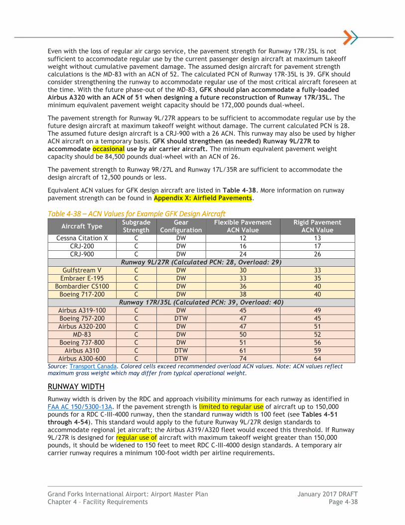
Grand Forks International Airport: Airport Master Plan January 2017 DRAFT Chapter 4 – Facility Requirements Page 4-38
Even with the loss of regular air cargo service, the pavement strength for Runway 17R/35L is not sufficient to accommodate regular use by the current passenger design aircraft at maximum takeoff weight without cumulative pavement damage. The assumed design aircraft for pavement strength calculations is the MD-83 with an ACN of 52. The calculated PCN of Runway 17R-35L is 39. GFK should consider strengthening the runway to accommodate regular use of the most critical aircraft foreseen at the time. With the future phase-out of the MD-83, GFK should plan accommodate a fully-loaded Airbus A320 with an ACN of 51 when designing a future reconstruction of Runway 17R/35L. The minimum equivalent pavement weight capacity should be 172,000 pounds dual-wheel.
The pavement strength for Runway 9L/27R appears to be sufficient to accommodate regular use by the future design aircraft at maximum takeoff weight without damage. The current calculated PCN is 28. The assumed future design aircraft is a CRJ-900 with a 26 ACN. This runway may also be used by higher ACN aircraft on a temporary basis. GFK should strengthen (as needed) Runway 9L/27R to accommodate occasional use by air carrier aircraft. The minimum equivalent pavement weight capacity should be 84,500 pounds dual-wheel with an ACN of 26.
The pavement strength to Runway 9R/27L and Runway 17L/35R are sufficient to accommodate the design aircraft of 12,500 pounds or less.
Equivalent ACN values for GFK design aircraft are listed in Table 4-38. More information on runway pavement strength can be found in Appendix X: Airfield Pavements.
Table 4-38 – ACN Values for Example GFK Design Aircraft
Aircraft Type Subgrade Strength
Gear Configuration
Flexible Pavement ACN Value
Rigid Pavement ACN Value
Cessna Citation X C DW 12 13
CRJ-200 C DW 16 17
CRJ-900 C DW 24 26
Runway 9L/27R (Calculated PCN: 28, Overload: 29)
Gulfstream V C DW 30 33
Embraer E-195 C DW 33 35
Bombardier CS100 C DW 36 40
Boeing 717-200 C DW 38 40
Runway 17R/35L (Calculated PCN: 39, Overload: 40)
Airbus A319-100 C DW 45 49
Boeing 757-200 C DTW 47 45
Airbus A320-200 C DW 47 51
MD-83 C DW 50 52
Boeing 737-800 C DW 51 56
Airbus A310 C DTW 61 59
Airbus A300-600 C DTW 74 64 Source: Transport Canada. Colored cells exceed recommended overload ACN values. Note: ACN values reflect maximum gross weight which may differ from typical operational weight.
RUNWAY WIDTH
Runway width is driven by the RDC and approach visibility minimums for each runway as identified in FAA AC 150/5300-13A. If the pavement strength is limited to regular use of aircraft up to 150,000 pounds for a RDC C-III-4000 runway, then the standard runway width is 100 feet (see Tables 4-51 through 4-54). This standard would apply to the future Runway 9L/27R design standards to accommodate regional jet aircraft; the Airbus A319/A320 fleet would exceed this threshold. If Runway 9L/27R is designed for regular use of aircraft with maximum takeoff weight greater than 150,000 pounds, it should be widened to 150 feet to meet RDC C-III-4000 design standards. A temporary air carrier runway requires a minimum 100-foot width per airline requirements.

Grand Forks International Airport: Airport Master Plan January 2017 DRAFT Chapter 4 – Facility Requirements Page 4-39
PAVEMENT SURFACE
Runway 17R/35L pavement consists of a grooved asphalt pavement surface. Runway grooving improves aircraft stopping performance when runway contaminants are present (water, ice, snow, slush, etc.). Runway grooving or friction treatment is recommended by the FAA for primary and secondary runways at commercial service airports. FAA AC 150/5320-12C considers this to be high priority safety work. Runway 9L/27R has concrete pavement and a grooved surface. All remaining runways (17L/35R, 9R/27L) consist of concrete pavement surfaces without any grooved surface.
RUNWAY DESIGNATION
Runway designation is determined by the magnetic bearing (azimuth) of the runway centerline which is relative to the location of the magnetic north pole. The runway designator number is the whole number nearest the one-tenth of the magnetic azimuth along the runway centerline when viewed from the direction of aircraft approach.
The 2015 magnetic declination at GFK is 3° 16’ east, changing 0° 5’ west per year as the location of the magnetic north pole moves over time. Runway 17/35 should be re-designated in the future to 18/36. FAA will make a determination if runways are to be re-designated. Runway 8/26 was re-designated to Runway 9L/27R in October 2008. Any change to runway designation will be made at the discretion of FAA as it requires the update of national aeronautical publications, procedures and signage. The official FAA published magnetic declination is 6° east from 1985. See Table 4-39 for details.
Table 4-39 – Runway Designation Requirements
Runway Designation Existing Magnetic Bearing (2015)
Future Magnetic Bearing (2034)
Recommended Future Designation
Runway 17R/35L 176.76°/356.76° 175.07°/355.07° 18R/36L
Runway 17L/35R 176.77°/356.77° 175.09°/355.09° 18L/36R
Runway 9L/27R 86.74°/266.74° 85.05°/265.05° Same
Runway 9R/27L 86.77°/266.77° 85.10°/265.10° Same Source: National Oceanic and Atmospheric Association (NOAA), KLJ Analysis
PAVEMENT CONDITION
In 2015, the North Dakota Aeronautics Commission (NDAC) completed a pavement management system update for GFK. The typical useful life of a bituminous pavement ranges from 20 to 30 years if properly maintained. The useful life for a concrete pavement can extend to 40 years and beyond. A summary of the existing runway pavement condition with recommendations is contained in Table 4-40:
Table 4-40 – Runway Pavement Condition & Recommendations
Runway ID Pavement Condition Index (PCI) Action Plan (Lowest PCI)
Highest PCI Lowest PCI 0-5 Years 6-10 Years 11-20 Years
Runway 17R/35L 84 77 Maintain Reconstruct Maintain
Runway 17L/35R 81 80 Maintain Maintain Major Rehab.
Runway 9L/27R 93 90 Maintain Maintain Major Rehab.
Runway 9R/27L 97 Maintain Maintain Maintain
Source: North Dakota Aeronautics Commission Pavement Condition Assessment (2015), KLJ Analysis
Runway 17R/35L: Runway 17R/35L surface is approximately 15 years old and is in Good condition. The runway was originally constructed in 1963. While pavement sections are in good condition, the runway has also experienced pavement heaving in multiple sections. A sub-surface analysis is recommended in the short-term to determine the source of recent pavement section deterioration. Although PCI values suggest otherwise, major rehabilitation or reconstruction may be needed within the next 10 years. It may be beneficial to plan for major construction while time is still available to plan around any operational hurdles that may arise with the complete reconstruction of the main runway.

Grand Forks International Airport: Airport Master Plan January 2017 DRAFT Chapter 4 – Facility Requirements Page 4-40
Runway 17L/35L: Runway 17L/35R was originally constructed in August 1983 and is in Good condition. No major rehabilitation since original construction in 1983, Runway 17L/35R will approach the end of its useful life during this master planning period. Proper maintenance and care for the surface has allowed the pavement to stay in decent shape. It is recommended GFK continue to maintain Runway 17L/35R runway and plan for major rehabilitation sometime within this master planning period.
Runway 9L/27R: Runway 9L/27R was completed in August of 1992 and is still in excellent condition. The runway has an excellent PCI value considering that this pavement is 25 years old. It is recommended the airport continue to complete preventative pavement maintenance and extend the useful life of the surface. However, it is still in the best interest of the airport to consider major Runway 9L/27R pavement rehabilitation over the course of this planning period due to the original age of the pavement.
Runway 9R/27L: Runway 9R/27L was newly constructed in 2009 and commissioned in 2010. The runway is still in excellent condition. It is recommended the airport sponsor continue to monitor Runway 9L/27R pavement condition and apply preventative maintenance as required through the planning period.
More information on runway pavement condition can be found in Appendix X: Airfield Pavements.
DEFICIENCIES TO DESIGN STANDARDS
Known deficiencies to the existing runway design standards at GFK include:
Runway 17L/35R Object Free Area Penetrations (Vegetation) o Deficiency: Multiple bushes appear to penetrate the ROFA on the east side. Above-
ground objects protruding above the nearest point of the RSA would be cleared. o Action Plan: Some growth has been removed per WHMP recommendation. Recommend
airport sponsor remove remaining growth within the next three years and maintain beyond.
Runway 9L/27R Object Free Area Penetration (Airfield Road) o Deficiency: The airfield access road penetrates the ROFA on the south side near the
Runway 9L end. Objects non-essential for air navigation or aircraft ground maneuvering purpose must not be placed in the ROFA.
o Action Plan: Relocate airfield road outside of ROFA during next Taxiway B2 or roadway pavement rehabilitation project.
Any existing deficiencies to airport design standards would need to be noted in the ALP and a Modification to Design Standards requested from FAA if they are to remain.
Figure 4-1 depicts the existing airfield design standards, deficiencies and key facility needs.
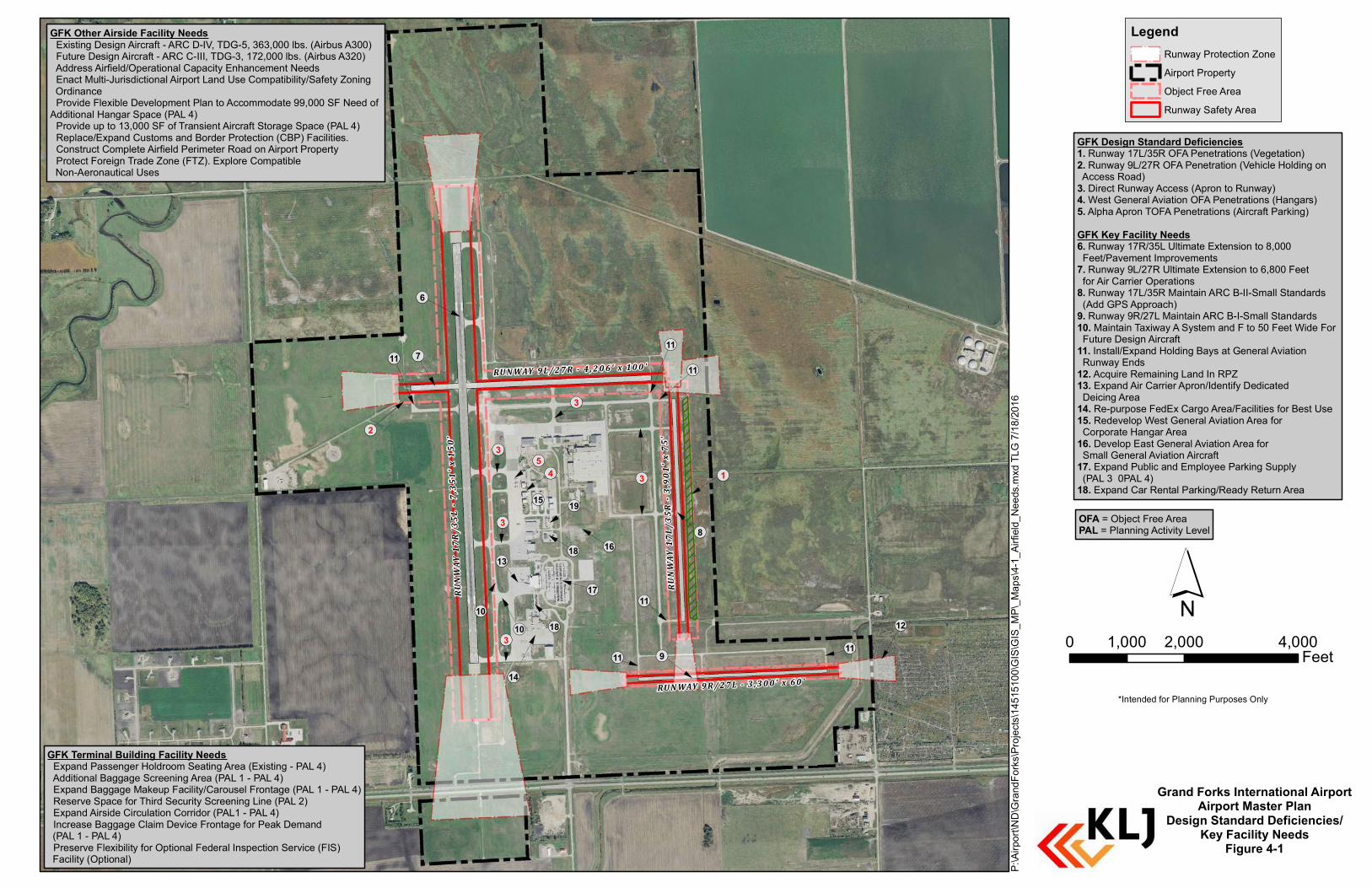
RU N WAY 9L / 2 7 R - 4 , 2 0 6' x 10 0 '
RUNW
AY 17
L/35
R - 3
,901
' x 7
5'
RU N WAY 9R / 2 7L - 3 , 3 0 0' x 60 '
RUNW
AY 17
R/35
L - 7
,351
' x 1
50'
!(3
!(4!(5
!(12
!(9
!(17
!(13
!(7
!(6
!(2
!(16!(18
!(19
!(14
!(10!(10
!(1
!(8
!(11!(11
!(11
!(11
!(18
!(15
!(3
!(3
!(3!(11
!(3
!(11
´
Grand Forks Inte rnational AirportAirport Maste r Plan
De sign Standard De ficie ncie s/Ke y Facility Ne e ds
Figu re 4-1
P:\Airport\ND\GrandForks\Projects\14515100\GIS\GIS_MP\_Maps\4-1_Airfield_Needs.mxd TLG 7/18/2016
0 2,000 4,0001,000Feet
Le ge ndRun wa y Protection Zon eAirport PropertyOb jec t Free AreaRun wa y Sa fety Area
*In ten ded for Pla n n in g Purposes On ly
GFK De sign Standard De ficie ncie s1. Run wa y 17L/35R OFA Pen etration s (V egetation )2. Run wa y 9L/27R OFA Pen etration (V ehic le Holdin g on Ac c ess Roa d)3. Direct Run wa y Ac c ess (Apron to Run wa y)4. W est Gen era l Avia tion OFA Pen etration s (Ha n ga rs)5. Alpha Apron TOFA Pen etration s (Aircra ft Parkin g)GFK Ke y Facility Ne e ds6. Run wa y 17R/35L Ultim a te Exten sion to 8,000 Feet/Pa vem en t Im provem en ts7. Run wa y 9L/27R Ultim a te Exten sion to 6,800 Feet for Air Carrier Operation s8. Run wa y 17L/35R M a in ta in ARC B-II-Sm a ll Sta n da rds (Add GPS Approa c h)9. Run wa y 9R/27L M a in ta in ARC B-I-Sm a ll Sta n dards10. M a in ta in Ta xiwa y A System a n d F to 50 Feet W ide For Future Design Aircra ft 11. In sta ll/Expa n d Holdin g Ba ys at Gen era l Avia tion Run wa y En ds12. Ac quire Rem a in in g La n d In RPZ13. Expa n d Air Carrier Apron /Iden tify Dedic a ted Deic in g Area14. Re-purpose FedEx Cargo Area/Fa c ilities for Best Use15. Redevelop W est Gen era l Avia tion Area for Corporate Ha n gar Area16. Develop East Gen era l Aviation Area for Sm a ll Gen era l Avia tion Aircra ft17. Expa n d Pub lic a n d Em ployee Parkin g Supply (PAL 3 – PAL 4) 18. Expa n d Car Ren ta l Parkin g/Rea dy Return Area
GFK Othe r Airside Facility Ne e ds• Existin g Design Aircra ft - ARC D-IV, TDG-5, 363,000 lb s. (Airb us A300)• Future Design Aircra ft - ARC C-III, TDG-3, 172,000 lb s. (Airb us A320)• Address Airfield/Operation a l Capa c ity En ha n c em en t Needs• En a c t M ulti-Jurisdic tion a l Airport La n d Use Com patib ility/Sa fety Zon in g Ordin a n c e• Provide Flexib le Developm en t Pla n to Ac com m oda te 99,000 SF Need of Addition a l Ha n ga r Spa c e (PAL 4)• Provide up to 13,000 SF of Tra n sien t Aircra ft Stora ge Spa c e (PAL 4)• Repla c e/Expa n d Custom s a n d Border Protection (CBP) Fa c ilities.• Con struct Complete Airfield Perim eter Roa d on Airport Property• Protect Foreign Tra de Zon e (FTZ). Explore Com patib le Non -Aeron a utic a l Uses
GFK Te rminal Bu ilding Facility Ne e ds• Expa n d Passen ger Holdroom Seatin g Area (Existin g - PAL 4)• Addition a l Ba gga ge Screen in g Area (PAL 1 - PAL 4)• Expa n d Ba gga ge M a keup Fa c ility/Carousel Fron ta ge (PAL 1 - PAL 4)• Reserve Spa c e for Third Sec urity Screen in g Lin e (PAL 2)• Expa n d Airside Circ ula tion Corridor (PAL1 - PAL 4)• In c rea se Ba gga ge Cla im Devic e Fron ta ge for Pea k Dem a n d (PAL 1 - PAL 4)• Preserve Flexib ility for Option a l Federa l In spection Servic e (FIS) Fa c ility (Option a l)
OFA = Ob jec t Free AreaPAL = Pla n n in g Activity Level

Grand Forks International Airport: Airport Master Plan January 2017 DRAFT Chapter 4 – Facility Requirements Page 4-42
Instrument Procedures
Instrument approach procedures to a runway end are used by landing aircraft to navigate to the airport during instrument conditions when the cloud ceiling is less than 1,000 feet and/or visibility is less than 3 miles. Establishing approaches with the lowest possible weather minimums allow the airport to maximize its operational utility. Each approach type requires differing infrastructure and navigational aids. Approaches with lower visibility minimums typically have additional infrastructure and navigational aids requirements. Types of approach procedures include non-precision approach (NPA), approach with vertical guidance (APV) and precision approach (PA).
This section discusses possible instrument procedure upgrades/options that can be explored for GFK. FAA airport design standards must be met as shown in Exhibit 4-41. Further coordination with FAA Flight Procedures Office is recommended to review the feasibility of implementing any new approach procedure.
Exhibit 4-41 – FAA Airport Design Standards for Instrument Approach Procedures
Source: FAA AC 150/5300-13A, Airport Design
RUNWAY 35L APPROACH
Runway 35L presently has the lowest approach minimums available on the airport. With a 200-foot ceiling height and ½ mile visibility, these approach minimums are achieved with an approach lighting system (MALSR) and an Instrument Landing System (ILS). An upgraded approach procedure with Category II (CAT-II) minimums could reduce the inaccessibility to the airport by over 50 percent.
Upgrading to a CAT-II approach would require a Benefit-Cost Analysis (BCA) to be completed. As identified in FAA Report ASP-76-1, Establishment Criteria for Category II Instrument Landing Systems (ILS), typically an airport with at least 2,500 certificated air carrier instrument approaches would be a candidate for an upgrade to a Category II ILS. When counting all scheduled commercial (non-UND)

Grand Forks International Airport: Airport Master Plan January 2017 DRAFT Chapter 4 – Facility Requirements Page 4-43
operations, GFK is not expected to meet this threshold in the planning period. FAA funding for such an improvement may be challenging.
FAA Order 8400.2, Procedures for the Evaluation and Approval of Facilities for…All Category II…Operations, FAA Order 6750.16D, Siting Criteria for Instrument Landing Systems and FAA AC 150/5300-13A Change 1, Airport Design all identify the facility requirements to accommodate a Category II ILS approach. For Runway 35L to have CAT-II minimums, the following infrastructure would be required:
Upgrading the existing MALSR approach lighting system to include Sequenced Flashing Lights (ALSF) equipment.
In-pavement lighting to include runway centerline and touchdown zone lighting.
Runway Visual Range (RVR) equipment at the touchdown, midfield, and rollout points located at least 400 feet from runway centerline.
Electrical improvements to provide standby power to activate within one second of primary power failure.
Other than upgrading to the equipment noted above, design standards would remain the same for the current runway configuration. The decision to ultimately upgrade Runway 35L to CAT-II minimums should be evaluated in the Alternatives Analysis chapter.
In the interim, GFK may be able to achieve enhanced CAT-I ILS approach with 1800 RVR with the following facilities and FAA approval:
In-pavement lighting to include runway centerline and touchdown zone lighting (TDZL)
Runway Visual Range (RVR) equipment at the touchdown point located at least 400 feet from runway centerline (installed at GFK).
RUNWAY 17R, 9L APPROACHES
The Runway 17R approach procedure with the best minimums is the RNAV (GPS) approach with vertical guidance with minimums as low as 264-foot cloud ceiling and 1-mile visibility (June 2016). Runway 9L has similar minimums with 250-foot cloud ceiling and 1-mile visibility. In certain instances, when strong winds blow from the south and east and the weather is below minimums, landing operations cannot occur.
An option to improve the usability of the airport is to lower the Runway 17R and 9L minimums on the RNAV (GPS) approach to no lower than ¾ mile and a ceiling height of feet. Lowering minimums to ¾ mile and 250-foot ceiling would allow for an additional 5 percent overall additional airport utility for Runway 17R, and 3 percent for Runway 9L when considering wind coverage.
Typically, to achieve lower minimums as low as to ¾ mile the following improvements would be required:
Implementation of a larger Runway Protection Zone (RPZ) of 1,700’ x 1,000’ x 1,510’ in size.
Outer width of Part 77 Approach Surface widens to 4,000 feet @ 10,000 feet.
Per FAA AC 150/5300-13A Change 1, obstacles must be clear from Table 3-2, Row 6 approach surface (and Row 8 approach surface for vertically guided approach).
Construction of at least a basic approach lighting system (i.e. ODALS).
Per Table 3-4 of FAA AC 150/5300-13A Change 1, no approach lighting system may be required to achieve ¾ mile approach. FAA requirements identify the maximum height above touchdown (cloud ceiling) to be 260 feet to achieve ¾ mile without a lighting system.
FAA Flight Procedures was contacted as part of this study for Runway 17R approach enhancements. If obstacles were removed near the Runway 17R approach, then the cloud ceiling could be lowered so that ¾ mile could be published without the need for an approach lighting system. Further FAA coordination is recommended.

Grand Forks International Airport: Airport Master Plan January 2017 DRAFT Chapter 4 – Facility Requirements Page 4-44
An approach lighting system would require the Inner Approach OFZ and Inner Approach OFZ Transitional Surface to be clear of objects not required for air navigation.
PRECISION RUNWAY 17R APPROACH
Implementing a precision instrument approach to Runway 17R (½ mile visibility minimums) would further improve the usability of Runway 17R’s RNAV (GPS) approach during IMC conditions. This improvement would improve the utility of this runway end by 19 percent the existing condition. To achieve lower minimums down to ½ mile, the following additional improvements would be required:
Construction of a full approach lighting system (i.e. MALSR).
Implementation of a larger Runway Protection Zone (RPZ) of 2,500’ x 1,000’ x 1,750’ in size.
Outer width of Part 77 Approach Surface widens to 4,000 feet @ 10,000 feet. An additional 40:1 surface applies out to 50,000 feet.
Per FAA AC 150/5300-13A Change 1, obstacles must be clear from Table 3-2, Row 7 approach surface (and Row 8 approach surface for vertically guided approach).
Implementation of Precision Obstacle Free Zone (POFZ) which must remain clear of objects not required for air navigation.
An upgrade of Runway 17R would likely need to be based on a GPS approach. Few new Instrument Landing Systems (ILS) are being implemented nationwide as the national airspace system is transitioning to minimize the use of ground-based navigational aids. FAA funding would be unlikely.
GENERAL AVIATION RUNWAY APPROACHES
Runways 17L/35R and 9R/27L have existing visual approaches. With advancements in GPS technology, and the progression towards satellite-based navigation systems eventually becoming the standard for air-navigation, it is recommended GFK explore ultimate RNAV (GPS) approaches for the remaining four (4) visual approaches on the airfield. Runway 17L/35R would provide particular operational benefit to serve east General Aviation hangars. This would require some changes to the airfield to provide additional instrument procedures for the flight training traffic utilizing the airfield. To achieve RNAV (GPS) approaches on these four runway ends, the following improvements would be required:
Painting of non-precision runway markings for Runways 17L/35R and 9R/27L
Completion of aeronautical survey requirements (included in this Airport Master Plan)
FAR Part 77 Primary Surface widens from 250 feet to 1,000 feet.
Outer width of Part 77 Approach Surface widens to 2,000 feet @ 5,000 feet.
Per FAA AC 150/5300-13A Change 1, obstacles must be clear from Table 3-2, Row 4 approach surface (and Row 8 approach surface for vertically guided approach).
Implementing a non-precision GPS approach to Runway 17L/35R is recommended. The decision to upgrade instrument approaches to accommodate the additional infrastructure needed for lowered instrument approach visibility minimums will be evaluated in the Chapter 5: Alternatives Analysis.
Airspace Protection
Airspace is an important resource around airports that is essential for safe flight operations. There are established standards to identify airspace obstructions around airports. FAA grant assurances (obligations) require the airport sponsor to take appropriate action to assure that airspace is adequately cleared to protect instrument and visual flight operations by removing, lowering, relocating, marking or lighting, or otherwise mitigating existing airport hazards and preventing the establishment or creating of future airport hazards. Examples of obstructions include trees, buildings, poles, towers, terrain, mobile objects and aircraft tails. Sufficiently clear airspace near the approach and departure runway ends are vitally important for safe airport operations. An FAA aeronautical study should be completed to determine the operational impacts and necessary mitigation of obstructions (i.e. lowering, lighting, marking, publish operational restrictions).

Grand Forks International Airport: Airport Master Plan January 2017 DRAFT Chapter 4 – Facility Requirements Page 4-45
As of the time of this report, an obstruction analysis is underway to identify obstructions to Part 77 and other airspace surfaces utilizing Aeronautical Survey data collected in September 2015. There are no known airspace penetrations to the existing FAA airport design runway approach (threshold siting) surfaces. There may be obstacles that penetrate other airspace surfaces that require further study. The full results of this analysis will be identified in the ALP drawing set. An Obstacle Action Plan in accordance with 2015 FAA guidance will be developed from these results and identified in the ALP.
AREA AIRSPACE
The airspace classification including and within 5 nautical miles of GFK at 3,300 feet MSL and lower is Class D controlled airspace. Airport Traffic Control Tower (ATCT) safely and efficiently handles all operations within this airspace. There is also Terminal Radar Control (TRACON) service provided beyond the limits of Class D airspace for IFR aircraft and available to VFR aircraft. Class E airspace to the surface extends approximately an additional 3 miles to the north and south of the airport. The existing airspace classifications in the GFK area is considered sufficient to support any enhancement to instrument approach procedures.
PART 77 CIVIL AIRPORT IMAGINARY SURFACES
Title 14 CFR (Code of Federal Regulations) Part 77 Safe, Efficient Use, and Preservation of the Navigable Airspace is used to determine whether man-made or natural objects penetrate these “imaginary” three-dimensional airspace surfaces and become obstructions. Federal Aviation Regulation (FAR) Part 77 surfaces are the protective surfaces most often used to provide height restriction zoning protection around an airport. Sufficiently clear airspace is necessary for the safe and efficient use of aircraft arriving and departing an airport. Part 77 airspace standards are defined by the most demanding approach to a runway. These airspace surfaces include the primary, approach, transitional, horizontal and conical surfaces each with different standards. The slope of an airspace surface is defined as the horizontal distance traveled for every one vertical foot (i.e. 50:1).
Of note are the primary surfaces which should be kept clear of non-essential objects above the runway centerline elevation. The approach surface extends upward an outward from the runway a slope defined as the horizontal distance traveled for every one vertical foot. Table 4-42 depicts the existing, future and ultimate approach airspace surfaces for GFK:
Table 4-42 – Part 77 Approach Airspace Requirements Runway
End Approach Standards
Part 77 Code
Inner Width*
Outer Width
Length Slope
Existing
17R Non-Precision
Other-Than-Utility As low as 1 mile
C 1,000’ 3,500’ 10,000’ 34:1
35L Precision
Other-Than-Utility As low as ½ Mile
PIR 1,000’ 16,000 50,000’ 50:1/40:1
17L Visual Utility A(V) 250’ 1,250’ 5,000’ 20:1
35R Visual Utility A(V) 250’ 1,250’ 5,000’ 20:1
9L Non-Precision
Other-Than-Utility As low as 1 mile
C 500’ 3,500’ 10,000’ 34:1
27R Non-Precision
Other-Than-Utility C 500’ 3,500’ 10,000’ 34:1
9R Visual Utility A(V) 250’ 1,250’ 5,000’ 20:1
27L Visual Utility A(V) 250’ 1,250’ 5,000’ 20:1

Grand Forks International Airport: Airport Master Plan January 2017 DRAFT Chapter 4 – Facility Requirements Page 4-46
Runway End
Approach Standards Part 77 Code
Inner Width*
Outer Width
Length Slope
Future
17R Non-Precision
Other-Than-Utility No lower than ¾ mile
D 1,000’ 4,000’ 10,000’ 34:1
9L Non-Precision
Other-Than-Utility No lower than ¾ mile
D 1,000’ 4,000’ 10,000’ 34:1
Ultimate
17L Non-Precision Utility
As low as 1 mile A(NP) 500’ 2,000 5,000’ 20:1
35R Non-Precision Utility
As low as 1 mile A(NP) 500’ 2,000 5,000’ 20:1
Source: Title 14 CFR Part 77, KLJ Analysis *Inner width is also the Primary Surface width driven by the most demanding approach to a runway. Bold indicates change from existing standard.
New development should be kept below the Part 77 airspace surface elevation. Airspace surfaces must clear public roads by 15 feet, interstate highways by 17 feet, railroads by 23 feet, and private roads by 10 feet or the height of the most critical vehicle.
Any existing, future or ultimate Part 77 obstructions located around GFK that will be identified on the ALP for further action.
RUNWAY APPROACH/DEPARTURE SURFACES
FAA identifies sloping approach surfaces that must be cleared at an absolute minimum for safety for landing aircraft. These surfaces are identified in Table 3-2 of FAA AC 150/5300-13A, Change 1. All objects must clear the surface for the applicable runway operational design standard to meet minimum aviation safety standards for a given runway landing threshold location. Approach airspace penetrations typically require the removal of the object, operational restrictions or the runway landing threshold to be shifted or displaced down the runway.
The departure surface applies to instrument departures. It begins at the end of the takeoff distance available and extends upward and outward at a 40:1 slope. No new penetrations are allowed unless an FAA study has been completed and a determination of no hazard has been issued. Penetrations to the departure surface may require the obstacle to be published, or require mitigation including increasing the minimum aircraft climb rate or runway length operational restrictions. Per Table 4-43, the following approach/departure surface standards apply:

Grand Forks International Airport: Airport Master Plan January 2017 DRAFT Chapter 4 – Facility Requirements Page 4-47
Table 4-43 – Approach/Departure Surface Requirements Runway End(s)
Table 3-2 Row
Description Slope
Existing
17L, 35R, 9R, 27L
2 Approach end of runways expected to serve small airplanes with
approach speeds of 50 knots or more (visual, day/night) 20:1
9L, 27R 4 Approach end of runways expecting to support instrument night
operations, serving approach Category A and B aircraft only 20:1
17R 5 Approaches supporting instrument night operations in greater
than Category B aircraft 20:1
35L 7 Instrument approaches having visibility minimums < ¾ statute
mile 34:1
35L, 17R, 9L, 27R
8 Approach end of runways to accommodate approaches with
vertical guidance 30:1
All 9 Departure runway ends for all instrument operations 40:1
Future
17R, 9L 6 Approach end of runways expected to accommodate instrument approaches having visibility minimums greater than or equal to
¾ mile but less than 1 statute mile 20:1
Ultimate
17L, 35R 4 Approach end of runways expected to support instrument night
operations, serving approach Category A and B aircraft only 20:1
17L, 35R 8 Approach end of runways to accommodate approaches with
vertical guidance 30:1
Source: FAA AC 150/5300-13A, Change 1, KLJ Analysis Note: Most critical row(s) shown. Only changes from existing shown in future.
All runway ends are available for instrument departures. There are penetrations to the existing Runway 9L, 27R, 35L and 35R instrument departure surfaces that are noted in FAA publications (see adjacent figure). All existing FAA approach surfaces are clear of obstructions.
Airspace surface obstructions and mitigation options for future runway configurations will be evaluated in Chapter 5: Alternatives Analysis. Mitigation options generally include obstruction removal, lighting/marking, declared distances and/or adjustment of the visual guidance slope indicator angle. Other long-term options include reconfiguring the runway or modifying design standards. New development should be clear of airspace surfaces.
TERMINAL INSTRUMENT PROCEDURES (TERPS)
The FAA has established standards to develop instrument procedures in the United States. FAA Order 8260.3B, U.S. Standards for Terminal Instrument Procedures (TERPS) and related orders outlines these complex standards to develop instrument procedures. Some critical obstruction clearance surface (OCS) standards are integrated into the FAA identified in Airport Design including many final approach segments and the departure surface. Other inner airport OCS include the precision obstacle clearance surfaces and the missed approach surfaces. Some TERPS surfaces may even be more restrictive that Part 77 standards. Penetrations to TERPS surfaces result in higher weather minimums or operational restrictions.
The following GPS instrument approach procedure has higher than typical approach weather minimums, signifying an obstruction or several obstructions causing these higher minimums:

Grand Forks International Airport: Airport Master Plan January 2017 DRAFT Chapter 4 – Facility Requirements Page 4-48
RNAV(GPS) RWY 17R: 264’ Height Above Touchdown (HAT) vs. 250’ HAT Typical
A full TERPS study is not planned at this time, however coordination with FAA Flight Procedures Office is recommended to identify the critical obstruction within each instrument approach. The instrument approach minimums to other runway ends are as low as possible for the current infrastructure, indicating there are no obstructions at this time that cause any higher minimums.
Every three years the FAA will conduct a review of the most critical final approach “visual area” TERPS surfaces to verify compliance. There are no existing penetrations to the visual area surfaces at GFK.
ONE ENGINE INOPERATIVE (OEI) SURFACES
One Engine Inoperative (OEI) procedures are developed by air carriers to clear obstacles in situations where one engine becomes inoperative. OEI obstacle surfaces have shallow slopes to provide object clearance when aircraft climb performance is reduced as a result of engine power loss. OEI procedures are developed by each airline. Critical obstructions effect the utility of the runway by these aircraft. The FAA had required a clear 62.5:1 sloped surface to be kept clear of obstacles from departure ends. The 62.5:1 OEI surface is no longer required by FAA because of the large area covered, the scope of obstructions found and inability for airport sponsors to clear these areas.
As of April 2014, the FAA published a Federal Register proposing to have airports develop individual OEI departure area in coordination with FAA. Submittal to FAA will enable the OEI surface to be consolidated so that the effects of new structure encroaching them can be evaluated under Part 77. In lieu of developing a new surface at this time, we recommend a standard 62.5:1 surface be used for future runway, airspace and land use planning if possible.
OTHER DESIGN SURFACES
Other airport design airspace surfaces considered protect navigational aids and identify airport data to populate FAA databases.
Inner-Approach Obstacle Free Zones Runway 35L has an existing approach lighting system. As a result, a clear inner-approach OFZ is necessary. The inner-approach OFZ is a 50:1 sloped surface begins 200 feet from the runway threshold and extends 200 feet beyond the last approach light (2,700 feet from runway end). The existing Inner-Approach OFZ to Runway 35L is clear of all obstacles.
Inner-Transitional Obstacle Free Zones The inner-transitional OFZ airspace surface is required for future visibility minimums lower than ¾ mile along the sides of the ROFZ. Objects not necessary for airport operations, including aircraft tails cannot penetrate this surface. Runway 17R/35L does not have existing penetrations to the Inner-Transitional OFZ.
Precision Obstacle Free Zone (POFZ) If a future precision instrument approach with minimums lower than ¾ mile is established there exists as POFZ which begins at the runway threshold as a flat surface 800 feet wide centered on the runway centerline and extending 200 feet to connect to the inner-approach OFZ. As with the OFZ, objects not necessary for airport operations including aircraft or vehicles on the ground cannot penetrate this surface. Runway 35L has an existing Precision OFZ which is clear of obstacles.
VISUAL AID SURFACES
Visual aids at an airport require clear Obstacle Clearance Surface (OCS) to provide sufficient guidance for pilots. These include approach lighting systems and visual guidance slope indicators. For a Precision Approach Path Indicator (PAPI) system, a 31.29:1 sloped surface must be clear. The specific airspace standards for this and for approach lighting systems are defined in FAA Order 6850.2B. After a cursory review, there are no known obstructions to visual aid surfaces at GFK.

Grand Forks International Airport: Airport Master Plan January 2017 DRAFT Chapter 4 – Facility Requirements Page 4-49
FAA AERONAUTICAL SURVEYS
The FAA has implemented Aeronautical Survey requirements per FAA AC 150/5300-18B: General Guidance and Specifications for Submission of Aeronautical Data to NGS: Field Data Collection and Geographic Information System (GIS) Standards. FAA airport survey requirements require obstruction data to be collected using assembled aerial imagery for the airport. This data is used in aeronautical publications and to develop instrument approach procedures.
An aeronautical survey is currently in progress with this planning effort as required by FAA. Imagery was acquired in September 2015. When safety-critical data is needed to update runway end data or enhance an instrument approach then a new aeronautical survey is required. All projects at primary FAR Part 139 certificated airports must comply with Airports GIS standards for all development projects.
Navigational Aids (NAVAIDs)
Airfield NAVAIDs are any ground or satellite based electronic or visual device to assist pilots with airport operations. They provide for the safe and efficient operations of aircraft on an airport or within the vicinity of an airport. The type of NAVAIDS required are determined by FAA guidance based on an airport’s location, activity and usage type.
AREA NAVIGATION
The FAA is updating the nation’s air transportation infrastructure through the Next Generation Air Transportation System (NextGen) program. New procedures and technology are to be implemented to improve the efficiency and safety of the national air transportation system. By 2020, all aircraft in controlled airspace must be equipped with Automatic Dependent Surveillance-Broadcast (ADS-B) equipment, forming the foundation by moving from group radar and navigation aids to precise tracking using satellite signals. As aircraft are required to be equipped with ADS-B, a trend in future aviation operations suggests satellite-based equipment will become the new normal for pilots.
For area navigation (RNAV), satellite-based NAVAIDs will primarily be used for air navigation with ground-based NAVAIDs used for secondary purposes. Wide Area Augmentation System (WAAS) provides the framework for satellite–based navigation and approach procedures. GFK has satellite-based approaches for all air carrier runways.
The existing ground-based VOR system in the northwest portion of GFK has design standards that should be met to support continued operation. The high-altitude GFK VOR/DME is owned by the FAA. This facility is identified as a retained VOR in the FAA’s national VOR minimum operational network. Maintaining the existing VOR facility at GFK is recommended.
To support existing VOR operations, the ground profile within 1,000 feet of the facility should be flat or graded downward. The actual elevations appear to have positive grade changes. A clearance angle of 1.2 degrees for metal structures and 2.0 degrees for trees is required. There are no known obstacles. Avoidance of the VOR critical area is the reason the airport perimeter fence was constructed along the edge of County Highway 5 and 40th Avenue North.
RUNWAY APPROACH
Other NAVAIDs are developed specifically to provide “approach” navigation guidance, which assists aircraft in landing at a specific airport or runway. These NAVAIDs are electronic or visual in type. FAA Order 6750.16D, Siting Criteria for Instrument Landing Systems and FAA Order 6850.2B, Visual Guidance Lighting Systems defines the standards for establishing these systems.
Precision Approach Categories There are three categories of precision instrument approaches systems – visibility minimums less than ¾ mile. Each category is capable of supporting approaches in equipped aircraft with lower weather minimums. Each category also requires an increasing complexity of airport equipment as well as aircraft and flight crew certifications. Runway 35L has an existing precision approach. With a ½ mile

Grand Forks International Airport: Airport Master Plan January 2017 DRAFT Chapter 4 – Facility Requirements Page 4-50
visibility and 200ft decision height, the precision approach is classified as a Category I ILS (see Table 4-44).
Table 4-44 – Precision Approach Categories Approach Category Decision Height (ft.) Runway Visual Range
(ft.) Equivalent Visibility
Category I 200 2,400 or 1,800 ½ mile or 3/8 mile
Category II 100 1200 ¼ mile
Category III 100 -> 0 700 -> 0 ¼ mile -> 0
Source: FAA Aeronautical Information Manual
Instrument Landing System (ILS) An ILS is a ground-based system that provides precision instrument guidance to aircraft approaching and landing on a runway. ILS approaches enable a safe landing in IMC with low cloud ceiling and/or visibility. Major components of ILS include the localizer antenna for horizontal guidance, glide slope antenna for vertical guidance and an approach lighting system. The localizer and glide slope require critical areas that are sufficiently graded and do not contain certain objects.
At this time, no new ILS systems are being installed nationwide. FAA’s policy in FAA Order 5100.38D, AIP Handbook states that the development of a GPS approach will be used instead of installation of a new CAT-I ILS at all locations where technically feasible. These approaches provide nearly the same equivalent capabilities. GFK should plan to utilize GPS technology for approach upgrades. This technology exists today with the existing approach procedures. Ultimately, the ground-based localizer and glideslope systems may eventually be replaced by precision GPS systems.
Visual Guidance Slope Indicator (VGSI) A VGSI system provides visual descent guidance to aircraft on approach to landing. A Precision Approach Path Indicator (PAPI) system and a Visual Approach Slope Indicator (VASI) are two typical VGSI systems. They are installed on runway ends to enhance visual vertical guidance to the runway end. PAPI systems, a newer technology, consist of a single row of two to four lights. The two light system is for non-jet runways and the four light system is for jet-capable runways.
GFK currently has 4-box PAPI systems on Runway 9L, 17L, 17R, 35L, and 35R. Runway 9R/27L has a 2-box PAPI system and Runway 27R has a VASI system. VASI systems have been noted as an older and outdated VGSI system. In the future, GFK should upgrade the existing VASI system on Runway 27R to a 4-box PAPI when the existing system reaches the end of its useful life. All PAPIs should meet obstacle clearance requirements.
Runway End Identifier Lights (REIL) REILs consist of high-intensity flashing white strobe lights located on the approach ends of runways to assist the pilot in early identification of the runway threshold. Additionally, these are typically installed on runways that are surrounded by a preponderance of other lights or if the runway lacks contrast with surrounding terrain. These are not installed with an approach lighting system.
GFK currently has two runway ends with REILs installed (17R and 27R). These REILs should be maintained through the long-term. It is recommended a REIL be installed for Runway 9L and any other visual runway approach end that establishes a GPS approach in the future. REILs are currently unidirectional, but omnidirectional could be acceptable as well. Unidirectional could be considered if circling approaches are common.

Grand Forks International Airport: Airport Master Plan January 2017 DRAFT Chapter 4 – Facility Requirements Page 4-51
Approach Lighting System (ALS) ALS help pilots transition from instrument flight to visual flight for landing. FAA encourages airport operators to consider an ALS to enhance the safety of an instrument approaches. An ALS installed on non-precision approach runways can help provide visibility credit for instrument approach minimums. A full ALS allows for cloud ceiling minimums below 250 feet. An upgraded ALS is also required for Category II ILS approach. There are various configurations, lighting types and complexities to these systems. The requirement for an airport runway end is dependent upon the type of precision approach and visibility minimums of the approach.
Common types of ALS to consider at GFK include:
Omnidirectional Approach Lighting System (ODALS): This basic ALS consists of seven omnidirectional sequenced strobe lights along runway approach centerline. The system is 1,500 feet in total length providing visual guidance to non-precision runways. GFK does not have an
existing approach with an ODALS lighting system.
Medium-intensity Approach Lighting System with Sequencing Flashing Lights (MALSF): This intermediate ALS consists of seven rows of lights, three flashing lights and a row of steady burning green lights prior to runway threshold. The system is 1,400 feet in total length providing visual guidance to non-precision runways. GFK does not have an existing approach with an MALSF lighting system.
Medium-intensity Approach Lighting System with Runway Alignment Indicator Lights (MALSR): This full ALS consists of seven rows of lights, five flashing lights and a row of steady burning green lights prior to runway threshold. The system is 2,400 feet in total length. This is required for a Category I precision instrument approach. The Runway 35L approach at GFK has
a MALSR lighting system.
Approach Lighting System with Sequenced Flashing Lights (ALSF): This full ALS is a more complex lighting system required for Category II precision approach. The system includes a green threshold bar, 15 total rows of white lights, nine side rows bars along centerline, and sequenced flashing white lights totaling 2,400 feet in length. GFK does not have an existing
approach with an ALSF lighting system.
See Exhibit 4-45 for example ALS configurations to consider at GFK.
Typical Approach Lighting System (FAA)

Grand Forks International Airport: Airport Master Plan January 2017 DRAFT Chapter 4 – Facility Requirements Page 4-52
Exhibit 4-45 – ALS Configurations
Source: FAA AC 150/5300-13A, Change 1, FAA Order 6850.2B, Visual Guidance Lighting Systems
To achieve a CAT-II approach with 1600 RVR (1/4 mile), an ALSF-2 approach lighting system is recommended for Runway 35L. In conjunction with touchdown zone lighting, runway centerline lighting and implementing an RVR system, ¼ mile visibility could be achieved and would increase the usability of the airport during poor weather conditions.
If an ALS is required to achieve ¾ mile visibility, it is recommended an MALSF system be planned for Runway 17R and 9L approaches. This ALS may assist the airport in achieving down to ¾ mile visibility approaches and would increase usability of the airfield during poor weather conditions when wind is blowing from a southerly direction. Presently, the lowest minimums are not lower than 1 mile with vertical guidance.
ODALS MALSF
ALSF MALSR

Grand Forks International Airport: Airport Master Plan January 2017 DRAFT Chapter 4 – Facility Requirements Page 4-53
AIRFIELD VISUAL
Visual NAVAIDs provide airport users with visual references within the airport environment. They consist of lighting, signage and pavement markings on an airport. Visual NAVAIDS are necessary airport facility components on the airfield, promoting enhancing situational awareness, operational capability and safety. FAA AC 150/5340-30, Design and Installation of Airport Visual Aids defines the standards for these systems.
Airport Beacon The airport beacon serves as the airport identification light so approaching pilots can identify the airport location from sunset to sunrise. The airport beacon’s location at GFK adequately serves the airport without known obstructions to its line of sight. The minimum light beam angle is 2 degrees.
Runway Lighting Runway edge lights are placed off the edge of the runway surface to help pilots define the edges and end of the runway during night and low visibility conditions. Runway lights are classified according to the intensity of light they produce including high intensity (HIRL), medium intensity (MIRL) and low intensity (LIRL).
With the exception of Runway 17R/35L, the remaining three (3) runways are equipped with Medium Intensity Runway Lighting (MIRL) systems. Runway 17R/35L is equipped with a High Intensity Runway Lighting System (HIRL). Based on discussions with the sponsor, the existing HIRL system on Runway 17R/35L has reached the end of its useful life. Installed in 2001 when the runway was rehabilitated, it has currently become unreliable to the point where failures have become common. Testing performed in August 2015 supported the conclusion that the system has deteriorated. A HIRL replacement on Runway 17R/35L is recommended in the future.
Other runway lights are installed at airports to facilitate the safe and efficient operation of aircraft. These include runway centerline lighting (RCL), touchdown zone lighting (TDZL), land and hold short lighting systems (LAHSO) and runway status light (RWSL). Runway 17R/35L is equipped with some in-pavement runway edge lights. In-pavement runway centerline lighting for Runway 17R/35L and touchdown zone lighting for Runway 35L is recommended to help the airport achieve 1800 RVR minimums in the future.
Taxiway Lighting Taxiway edge lighting delineates the taxiway and apron edges. The FAA standard taxiway edge lighting system is Medium Intensity Taxiway Lights (MITL).
With the exception of Runway 17R/35L’s Taxiway system, the entire taxiway system at GFK operates with Medium Intensity Taxiway Lighting (MITL). Runway 17R/35L’s taxiway Alpha (A) and associated entrance taxiways are equipped with High Intensity Taxiway Lighting (HITL). It is recommended the airport continue to maintain the MITL system on the airfield, as well as the HITL system on Taxiway A.
Lighting Activation During towered operations, lighting is controlled by Air Traffic Control. When the tower is not operational, lighting is pilot controlled through Common Traffic Advisory Frequency (CTAF). There are no known issues with how airfield lighting is activated at GFK.
AIRFIELD SIGNAGE
Airfield signage is essential for the safe and efficient operation of aircraft and ground vehicles on the airport movement area. Common signs include mandatory instruction signs, location signs, boundary signs, direction/destination signs, information signs and distance remaining signs.
GFK has mandatory, locational, and directional signage on the airfield. All types of signage are lighted and marked in accordance with FAA AC 150/5340-18F, Standards for Airport Sign Systems. These signs are maintained by the airport maintenance staff and are in fair condition.

Grand Forks International Airport: Airport Master Plan January 2017 DRAFT Chapter 4 – Facility Requirements Page 4-54
Airports certificated under 14 CFR Part 139 such as GFK must have a sign plan developed and implemented to identify taxi routes and holding positions. This plan must be consistent with FAA Advisory Circular 150/5340-18F. This plan should be maintained to meet current standards and operating procedures.
PAVEMENT MARKINGS
Pavement markings help airport users visually identify important features on the airfield. FAA has defined numerous different pavement markings to promote safety and situational awareness as defined by FAA AC 150/5340-1, Standards for Airport Markings.
Runway Runway pavement markings are white in color. The type and complexity of the markings are determined by the approach threshold category to the runway end. The minimum required runway markings for a standard runway are as follows:
Visual (landing designator, centerline)
Non-Precision (landing designator, centerline, threshold)
Precision (landing designator, centerline, threshold, aiming point, touchdown zone, edge)
The following recommendations are made for GFK runway markings:
Maintain Runway 17R/35L precision instrument markings.
Maintain Runway 9L/27R non-precision instrument markings
Maintain Runway 9R/27L visual runway markings
Upgrade Runways 17L/35R to non-precision runway markings in conjunction with the ultimate recommendation of adding RNAV GPS approaches.
Taxiway/Taxilane Taxiway and taxilane markings are important for directional guidance for taxiing aircraft and ground vehicles. Common taxiway and apron markings include taxiway/taxiway centerline, edge and non-movement area boundary. Enhanced taxiway markings are required along taxiway centerlines that lead to runway entrances. Taxiway/taxilane centerline markings should be used throughout to define a safe centerline with object clearance. Taxiway/taxilane edge markings should be used to delineate the taxiway edge from the shoulder, apron or some other contiguous paved surface. The non-movement area boundary should be marked appropriately per ATCT line of sight requirements.
GFK’s taxiway/taxilane markings are maintained by airport maintenance staff and are in good condition. They include taxiway/taxilane centerlines, enhanced centerlines, movement/non-movement markings, runway hold-lines, and painted holding position signs (markings on pavement) on all runway hold lines and applicable taxiways/taxilanes. There are no long-term modification recommendations for taxiway/taxilane markings at GFK.
Holding Position Holding position markings are a visual reference to prevent aircraft and vehicles from entering critical areas such as an active runway environment. These markings consist on yellow bars and dashes on a black background.
Accounting for altitude adjustments, the required holding position setbacks for runways at GFK include 258 feet from runway centerline for 17R/35L, 208 feet from runway centerline for Runway 9L/27R, and 133 feet from runway centerline for both Runway 17L/35R and 9R/27L. All four (4) runways meet FAA minimum design standard regarding holding position marking requirement. Actual runway-to-hold line marking distances include 265 feet for Runway 17R/35L, and 208 feet for runways 9L/27R, 17L/35R, and 9R/27L.

Grand Forks International Airport: Airport Master Plan January 2017 DRAFT Chapter 4 – Facility Requirements Page 4-55
METEOROLOGICAL
Aircraft operating to and from an airport require meteorological aids to provide current weather data. Weather information helps pilots make informed decision about flight operations. Airports have various aids installed providing local weather information.
Surface Weather Observation GFK has an existing FAA-owned Automated Surface Observation System (ASOS) located west of Runway 17R/35L and is anticipated to provide adequate weather service through this planning period. This system provides weather updates every 15 minutes, or updates when significant weather changes occur.
Wind Cone(s) GFK has an existing primary lighted wind cone west of Runway 17R/35L. There are also a smaller “secondary” wind cones located near each runway end. Wind cones allow pilots to instantly obtain real-time wind direction and speed information, which allows them to make decisions for aircraft operations during takeoff or landing.
Other Other meteorological aids can include electrical systems such as Runway Visual Range (RVR) systems. RVR systems aid in aircraft arrivals and departures during poor visibility conditions. An FAA-owned RVR system is installed at the touchdown zone of Runway 35L. The system is sufficient for current CAT-I operations. If GFK were to implement RVR-based minimums such as a CAT-II approach, an RVR system located at the touchdown, midfield and rollout points would be required.
COMMUNICATIONS & ATC
The ability for pilots to communicate with other pilots and air traffic control (ATC) is critical for the safety and efficiency of the overall air transportation system.
GFK operates Class D airspace with an Air Traffic Control Tower (ATCT) facility located in the northeast corner of the landside facilities on the airfield. Their normal operating hours are 6:00AM until 11:30PM. Outside of these towered hours, pilots navigate in and out of GFK through Class E airspace and “self-announce” their position and intentions on the CTAF frequency. ATCT operating hours should be adjusted accordingly for the expected volume of traffic.
The current GFK ATCT was constructed in 1973. The tower cab is approximately 420 SF in size and cab eye level is 933 feet Mean Sea Level (MSL) or 92 feet Above Ground Level (AGL). It is imperative that personnel in the tower be able to see the airfield under its control. In November of 2015, the FAA conducted a “Quick Look Evaluation” to evaluate the tower cab for any deficiencies. As a result of the study, no large-scale blockages were found from the current tower location in relation to all of the movement areas on the airfield. Partial, minor blockages exist where Charlie Apron meets Taxiway C1, and Taxiway A near Taxiway F. No detailed ATCT line-of-sight study was conducted in this Master Plan. The tower is in need of replacement; a FAA siting study is scheduled to be initiated by July 2017.
If a replacement ATCT is planned by FAA, FAA Order 6480.4A, Airport Traffic Control Tower Siting Process identifies the criteria used for considering a new tower location:
1. Visual performance 2. TERPS airspace surfaces 3. FAR Part 77 airspace 4. Sunlight/daylight 5. Airport/background lighting 6. Atmospheric Conditions 7. Industrial Municipal Discharge 8. Site Access 9. Interior Physical Barriers 10. Security

Grand Forks International Airport: Airport Master Plan January 2017 DRAFT Chapter 4 – Facility Requirements Page 4-56
The ALP will show the preferred site location based on a preliminary analysis. Additional research and modeling will be required prior to actual site selection. An ATCT siting study would be initiated and completed by FAA.
Taxiways
Taxiways provide for the safe and efficient movement of aircraft between the runway and other operational areas of the airport. The taxiway system should provide critical links to airside infrastructure, increase capacity and reduce the risk of an incursion with traffic on the runway. The taxiway system should meet the standards design requirements identified in FAA AC 150/5300-13A, Change 1.
SYSTEM DESIGN
FAA has placed a renewed emphasis on taxiway design in their updated airport design standards. Fundamental elements help develop and efficient system to meet demands, reduce pilot confusion and enhance safety. Considerations include:
Design taxiways to meet FAA design standards for existing and future users considering expandability of airport facilities.
Design taxiway intersections so the cockpit is over the centerline with a sufficient taxiway edge safety margin.
Simplify taxiway intersections to reduce pilot confusion using the three-node concept, where a pilot has no more than three choices at an intersection.
Eliminate “hot spots” identified by the FAA Runway Safety Action Team where enhanced pilot awareness is encouraged.
Minimize the number of runway crossings and avoid direct access from the apron to the runway.
Eliminate aligned taxiways whose centerline coincides with a runway centerline.
Other considerations include avoiding wide expanses of pavement and avoiding “high energy intersections” near the middle third of a runway.
In 2015, GFK took measures to relocate Taxiway Delta to correct a “hot spot” identified by FAA. There are two remaining “hot spots” noted in the area. The first hotspot is at the intersection of Runway 9L/27R and Taxiway Alpha. This hotspot pertains to north flow traffic on Taxiway Alpha and crossing Runway 9L/27R. The second hotspot is in the same area, and is located on Taxiway Bravo when crossing Runway 17R/35L while heading west on Taxiway Bravo. This hotspot was identified because of its tendency to have an increased risk of runway incursions.
Pertaining to these hotspots, there are no known design flaws to the taxiway system. This area is also known to be used by the University of North Dakota for pre-flight aircraft operations. It is possible that student pilot error could be a contributing factor to an increase of runway incursions in this area. No taxiway system configuration changes are recommended at GFK to resolve “hot spots”.
In general, the entire taxiway/taxilane layout at GFK was constructed with taxiways perpendicular to each other. All intersections on the airfield intersect at a 90-degree angle and is most desirable for aircraft safety and pilot awareness of other moving objects on the airfield (vehicles, other aircraft, etc.). Perpendicular intersections provide optimal visibility.
GFK Airport Diagram: Hot Spots
(FAA)

Grand Forks International Airport: Airport Master Plan January 2017 DRAFT Chapter 4 – Facility Requirements Page 4-57
Various taxiways provide “direct access” from the apron to the runway environment. Ultimately, direct access taxiways should be reconfigured to require a turn from the apron onto the parallel taxiway.
DESIGN STANDARDS
FAA identifies the design requirements for taxiways. The design standards vary based on individual aircraft geometric and landing gear characteristics. The Taxiway Design Group (TDG) and Airplane Design Group (ADG) identified for the design aircraft using a particular taxiway. In addition to taxiway/taxiway pavement width, some of the safety standards include:
Taxiway/Taxilane Safety Area (TSA): A defined graded and drained surface alongside the taxiway prepared or suitable for reducing the risk of damage to an aircraft deviating from the taxiway. The surface should be suitable to support equipment during dry conditions
Taxiway Edge Safety Margin (TESM): The minimum acceptable distance between the outside of the airplane wheels and the pavement edge.
Taxiway/Taxilane Object Free Area (TOFA): An area centered on the centerline to provide enhanced the safety for taxiing aircraft by prohibiting parked aircraft and above ground objects except for those objects that need to be located in the OFA for aircraft ground maneuvering purposes.
Other design standards include taxiway shoulder width to prevent jet blast soil erosion or debris ingestion for jet engines, and required separation distances to other taxiways/taxilanes. Table 4-46 and Table 4-47 describes the specific FAA taxiway design standards for various ADG and TDG design aircraft, respectively.
Table 4-46 – FAA Taxiway Design Standards Matrix (ADG)
Design Standard Airplane Design Group (ADG)
ADG-I ADG-II ADG-III ADG-IV
Taxiway Safety Area 49 feet 79 feet 118 feet 171 feet
Taxiway Object Free Area 89 feet 131 feet 186 feet 259 feet
Taxilane Object Free Area 79 feet 115 feet 162 feet 225 feet
Taxiway Centerline to Parallel Taxiway Centerline 70 feet 105 feet 152 feet 215 feet
Taxilane Centerline to Parallel Taxilane Centerline 44.5 feet 65.5 feet 93 feet 129.5 feet
Taxiway Centerline to Fixed or Movable Object 64 feet 97 feet 140 feet 198 feet
Taxilane Centerline to Fixed or Movable Object 39.5 feet 57.5 feet 81 feet 112.5 feet
Taxiway Wingtip Clearance 20 feet 26 feet 34 feet 44 feet
Taxilane Wingtip Clearance 15 feet 18 feet 27 feet 27 feet
Taxiway A “Alpha” X X
Taxiway B “Bravo” X X
Taxiway C “Charlie” X
Taxiway D “Delta” X X
Taxiway E “Echo” X
Taxiway F “Foxtrot” X X
Taxiway G “Golf” X
Taxiway S “Sierra” X
Taxiway U “Uniform” X
Alpha Apron (Taxilanes) X X
Bravo Apron (Taxilanes) X
Charlie Apron (Taxilanes) X
Air Carrier Apron (Taxilanes) X Source: FAA AC 150/5300-13A, Change 1, KLJ Analysis NOTE: Taxiways include respective entrance taxiways to runways; Green cell indicates planned change in future design standard

Grand Forks International Airport: Airport Master Plan January 2017 DRAFT Chapter 4 – Facility Requirements Page 4-58
Table 4-47 – FAA Taxiway Design Standards Matrix (TDG)
Design Standard Airplane Design Group (TDG)
TDG-1A TDG-2 TDG-3/4 TDG-5
Taxiway Width 25 feet 35 feet 50 feet 75 feet
Taxiway Edge Safety Margin (TESM) 5 feet 7.5 feet 10 feet 15 feet
Taxiway Shoulder Width 10 feet 15 feet 20 feet 30 feet
Crossover Taxiway Separation for Reverse Turns (Minimum)
70 feet 162 feet 162 feet 240 feet
Centerline Turn Radius (90 degrees) 35 feet 81 feet 81 feet 120 feet
Design Standard TDG-1A TDG-2 TDG-3/4 TDG-5
Taxiway A “Alpha” X X
Taxiway B “Bravo” X
Taxiway C “Charlie” X
Taxiway D “Delta” X X
Taxiway E “Echo” X
Taxiway F “Foxtrot” X X
Taxiway G “Golf” X
Taxiway S “Sierra” X
Taxiway U “Uniform” X
Alpha Apron (Taxilanes) X X
Bravo Apron (Taxilanes) X
Charlie Apron (Taxilanes) X
Air Carrier Apron (Taxilanes) X X Source: FAA AC 150/5300-13A, Change 1, KLJ Analysis NOTE: Taxiways include respective entrance taxiways to runways Green cell indicates planned change in future design standard
The existing airfield conditions has all parallel taxiways setback from their respective runway centerlines at a distance of 400 feet. This distance meets FAA design standard for Taxiway A and exceeds design standard for B, C, and S parallel taxiways.
The following are noted deficiencies to taxiway design standards:
Taxiways A3, A4, A5, B1, C1: o Deficiency: Taxiway configuration provides direct access from the aircraft parking
apron to the runway. Taxiways should be configured to require aircraft to make a 90 degree turn prior to entering the runway environment.
o Action Plan: It is recommended the taxiway connections between the runway and apron be reconfigured to meet FAA standards when pavement is due for reconstruction.
The following are noted deficiencies to taxilane design standards:
West General Aviation Hangar Area o Deficiency: The northernmost east-west taxilane does not meet ADG-I TOFA standards
(30 feet actual, 39.5 feet required). This same taxilane does not meet TDG-1A standard pavement width (24 feet actual, 25 feet required).
o Action Plan: As much of the infrastructure has exceeded its useful life and is failing, it is recommended the entire West General Aviation Hangar area be reconstructed and reconfigured to meet design standards.

Grand Forks International Airport: Airport Master Plan January 2017 DRAFT Chapter 4 – Facility Requirements Page 4-59
West General Aviation Hangar Area: o Deficiency: The easternmost north-south taxilane does not meet ADG-II TOFA standards
(50 feet actual, 57.5 feet required). The fleet mix of aircraft hangared in this area vary from ADG-I and ADG-II.
o Action Plan: As much of the infrastructure has exceeded its useful life and is failing, it is recommended the entire West General Aviation Hangar area be reconstructed and reconfigured to meet design standards.
Alpha Apron: o Deficiency: Several north-south taxilane does not meet ADG-II TOFA standards (45 feet
actual, 57.5 feet required) from parked aircraft. o Action Plan: It is recommended the aircraft parking positions/tie-downs and taxilane
centerlines be restriped to meet standards.
Bravo/Charlie Apron: o Deficiency: Multiple taxilanes do not meet ADG-I TOFA standards (33 feet actual, 39.5
feet required) from actual parked aircraft when accounting for the aircraft nose. The tie-down to tie-down separation is 80 feet.
o Action Plan: It is recommended the aircraft parking positions/tie-downs and taxilane centerlines be restriped to meet standards.
Figure 4-1 depicts the existing airfield design standards, deficiencies and key facility needs.
FAA taxiway fillet geometric design standards changed in 2012 with FAA AC 150/5300-13A. These standards should be incorporated at GFK during taxiway reconstruction or new construction.
ENTRANCE/EXIT TAXIWAYS
Entrance taxiways provide access to the runway ends for departures. Exit taxiways serve to achieve an efficient flow of traffic to reduce runway occupancy time and increase runway capacity. These taxiways are located along the runway in ideal aircraft deceleration and stop locations. High speed taxiways allow aircraft to exit a runway without having to decelerate to typical taxiway speed. Guidance from FAA AC 150/5300-13A, Change 1 and FAA AC 150/5060-5, Airport Capacity and Delay was used for this analysis.
Entrance taxiways should always be oriented 90 degrees to runway centerline to enhance visibility of runway operations. The outer edge of entrance taxiways at runway ends should also be curved. Entrance taxiways at GFK meet ADG standards throughout the airfield. Fillets on the airfield were constructed based on a previous FAA standard. As a result, fillets at GFK do not meet the current TDG standard. It is recommended, when pavements have reached the end of their useful life, that fillets and radii be reconstructed according to the updated FAA standards.
Exit taxiways should be aligned at 90 degrees (ideal), 45 degrees or 30 degrees for high-speed exit taxiways. Exit taxiways should be located along the runway in ideal locations to capture landing traffic to reduce runway occupancy times. The existing exit taxiway locations and configurations at GFK are deemed sufficient (see Table 4-48). Exit taxiways at GFK meet ADG standards throughout the airfield. As with entrance taxiways, fillets at GFK do not meet the current TDG standard as should be reconfigured to meet updated FAA standards when reconstructed.
The FAA recommends capacity enhancements when the peak hourly runway operations reach 30. Although runways exceed 30 operations per hour, no exit taxiways enhancements are recommended due to the slower aircraft approach speed of flight training aircraft. All taxiway exit locations and configurations appear to be sufficient for all aircraft types to minimize runway occupancy time.
BYPASS TAXIWAYS & HOLDING BAYS
Runway departure delays can be caused by aircraft awaiting departure clearance or completing pre-flight checks. Bypass taxiways and holding bays provide the flexibility to allow runway use when an aircraft is not ready for takeoff and would otherwise block the taxiway. Bypass taxiways provide a

Grand Forks International Airport: Airport Master Plan January 2017 DRAFT Chapter 4 – Facility Requirements Page 4-60
secondary access to runways, whereas holding bays a provide space for aircraft away from the taxiway environment. Both bypass taxiways and holding bays improve capacity and overall flow.
The FAA recommends capacity enhancements when the peak hourly runway operations reach 30, which GFK has already exceeds. Capacity enhancements can include holding bays and bypass taxiways. These improvements would especially help an airport like GFK that has a high-volume of flight training traffic reduce ground delays.
Currently, GFK operates with designated aircraft run-up areas throughout the airfield. Primarily, western-bound UND traffic completes aircraft run-up/checklist operations along Taxiway Delta directly east of the Alpha/Bravo taxiway intersection. East-bound UND traffic typically completes run-ups either at the intersection of Charlie and Bravo taxiways, or near the Runway 35R departure end. These run-up areas along taxiways can cause congestion as no bypass capability exists. Constructing holding bays with adequate bypass capability at the end of each runway end would help relieve this issue.
It is recommended the airport explore options to add holding bays or bypass taxiways to each of the runway ends. It was expressed by Air Traffic Control that holding bays at each runway end or by the Charlie Apron would help the flow of traffic and the sequencing of aircraft. If one aircraft behind another is ready for departure, it would be much easier to clear that aircraft from the holding bay and open up the traffic flow, rather than a bypass taxiway where the flow of traffic is limited to one aircraft at a time.
Table 4-48 – Exit Taxiway Utilization Percentages
Exit Type Distance from
Threshold
Wet Runway Dry Runway
S T L H S T L H
Runway 17R
Taxiway A2 Right Angle 1,400 feet 23 0 0 0 39 0 0 0
Taxiway B Right Angle 2,900 feet 96 10 0 0 100 39 0 0
Taxiway A3 Right Angle 4,010 feet 100 97 4 0 100 100 24 2
Taxiway A4 Right Angle 5,265 feet 100 100 27 0 100 100 75 24
Taxiway A5 Right Angle 7,350 feet 100 100 97 84 100 100 100 100
Runway 35L
Taxiway A4 Right Angle Acute Angle
2,085 feet 84 1 0 0 99 10 0 0
Taxiway A3 Right Angle 3,340 feet 99 41 0 0 100 81 2 0
Taxiway B Right Angle Acute Angle
4,450 feet 100 97 4 0 100 100 24 2
Taxiway A2 Right Angle 5,950 feet 100 100 48 10 100 100 92 71
Taxiway A1 Right Angle 7,350 feet 100 100 97 84 100 100 100 100
Runway 17L
Taxiway C1 Right Angle Acute Angle
510 feet 0 0 0 0 0 0 0 0
Taxiway C2 Right Angle 2,005 feet 84 1 0 0 99 10 0 0
Taxiway C3 Right Angle 3,900 feet 100 80 1 0 100 98 8 0
Runway 35R
Taxiway C2 Right Angle 1,900 feet 60 0 0 0 84 1 0 0
Taxiway C1 Right Angle Acute Angle
3,390 feet 99 41 0 0 100 81 2 0
Taxiway B Right Angle 3,900 feet 100 80 1 0 100 98 8 0
Runway 9L
Taxiway A Right Angle 1,300 feet 23 0 0 0 39 0 0 0
Taxiway B1 Right Angle Acute Angle
2,475 feet 84 1 0 0 99 10 0 0
Taxiway C Right Angle 4,200 feet 100 97 4 0 100 100 24 2

Grand Forks International Airport: Airport Master Plan January 2017 DRAFT Chapter 4 – Facility Requirements Page 4-61
Exit Type Distance from
Threshold
Wet Runway Dry Runway
S T L H S T L H
Runway 27R
Taxiway B1 Right Angle 1,725 feet 60 0 0 0 84 1 0 0
Taxiway A Right Angle Acute Angle
2,900 feet 96 10 0 0 100 39 0 0
Taxiway B2 Right Angle 4,200 feet 100 97 4 0 100 100 24 2
Runway 9R
Taxiway S2 Right Angle 1,120 feet 23 0 0 0 39 0 0 0
Taxiway S1 Right Angle Acute Angle
3,330 feet 99 41 0 0 100 81 2 0
Runway 27L
Taxiway S2 Right Angle 2,180 feet 84 1 0 0 99 10 0 0
Taxiway E Right Angle Acute Angle
3,330 feet 99 41 0 0 100 81 2 0
S = Small, single engine, 12,500 lbs. or less; T = Small, twin engine, 12,500 lbs. or less; L = Large, 12,500 lbs. to 300,000 lbs.; H = Heavy, 300,000 lbs. Source: FAA AC 150/5300-13A, Change 1, KLJ Analysis
PAVEMENT CONDITION & STRENGTH
A summary of the taxiway pavement condition with recommendations is in Table 4-49:
Table 4-49 – Taxiway Pavement Condition & Recommendations
Taxiway ID Pavement Condition Index (PCI) Action Plan (Lowest PCI)
Highest PCI Lowest PCI 0-5 Years 6-10 Years 11-20 Years
Taxiway A 100 72 Maintain Major Rehab. Maintain
Taxiway B 100 12 Reconstruction Maintain Maintain
Taxiway C 92 57 Maintain Major Rehab. Maintain
Taxiway D 100 Maintain Maintain Maintain
Taxiway E 98 Maintain Maintain Maintain
Taxiway F 95 Maintain Maintain Maintain
Taxiway G 74 Maintain Maintain Major Rehab.
Taxiway S 98 95 Maintain Maintain Maintain
Taxiway U 83 49 Major Rehab. Maintain Maintain
Source: North Dakota Aeronautics Commission Pavement Condition Assessment (2015), KLJ Analysis
The pavement strength of the taxiways serving air carrier runways was also reviewed with results in Table 4-50. Taxiway A is calculated to have a slightly lower pavement strength than Runway 17R/35L. Publishing the taxiway pavement strength as the runway pavement strength is recommended to avoid overweight operations on the runway-taxiway infrastructure. Strengthening Taxiway A is recommended to accommodate regular use of the future design aircraft (ACN: 51) for Runway 17R/35L.
Taxiway B and Runway 9L/27R are calculated to have the exact pavement strength. Any upgrade in runway pavement strength should also be completed to the associated taxiway into the future.

Grand Forks International Airport: Airport Master Plan January 2017 DRAFT Chapter 4 – Facility Requirements Page 4-62
Table 4-50 – Taxiway Pavement Strength Requirements
Taxiway (Runway) Existing Calculated Runway Existing Calculated Taxiway
Capacity PCN Capacity PCN
Taxiway A (17R/35L)
101,000 (SW)
39/R/B/W/T
108,000 (SW)
42/R/B/W/T 134,000 (DW) 152,000 (DW)
216,000 (DTW) 258,000 (DTW)
Taxiway B (9L/27R)
77,000 (SW)
28/R/C/W/T
77,000 (SW)
28/R/C/W/T 95,000 (SW) 95,000 (SW)
167,000 (STW) 167,000 (STW) Source: KLJ Analysis
Taxiways should generally be designed to accommodate the design aircraft to serve that particular area. At GFK these include:
Taxiways A, D, F: 172,000 pounds (DW), ACN: 52 – Primary Air Carrier
Taxiway B: 84,500 pounds (DW), ACN: 26 – Secondary Air Carrier
Taxiway G: 60,000 pounds (DW) – General Aviation
Taxiway C, E, S, U: 12,500 pounds (SW) – Small Aircraft
Airside Data Summary
The following tables provide summary data of the facility requirements and recommendations associated with each of the runways at GFK through the planning period(s) identified in this Master Plan study:
Table 4-51: Runway 17R/35L Design Standard Matrix
Table 4-52: Runway 17L/35R Design Standard Matrix
Table 4-53: Runway 9L/27R Design Standard Matrix
Table 4-54: Runway 9R/27L Design Standard Matrix

Grand Forks International Airport: Airport Master Plan January 2017 DRAFT Chapter 4 – Facility Requirements Page 4-63
Table 4-51 – Runway 17R/35L Design Standard Matrix
Design Standard Actual
Condition
Facility Requirement or Recommendation
Existing Future Ultimate
Runway Identification 17R/35L 18R/36L 18R/36L 18R/36L
Runway Classification Other-Than-Utility Other-Than-Utility Other-Than-Utility Other-Than-Utility
Aircraft Classification Large Aircraft Large Aircraft Large Aircraft Large Aircraft
Runway Design Code (RDC) D-IV-5000 (17R) D-IV-2400 (35L)
D-IV-5000 (17R) D-IV-2400 (35L)
C-III-4000 (17R) C-III-2400 (35L)
C-III-4000 (17R) C-III-1600 (35L)
Approach Reference Code (APRC)
D-IV-5000 (17R) D-V-5000 (17R) D-IV-2400 (35L) D-V-2400 (35L)
D-IV-5000 (17R) D-V-5000 (17R) D-IV-2400 (35L) D-V-2400 (35L)
D-IV-4000 (17R) D-V-4000 (17R) D-IV-2400 (35L) D-V-2400 (35L)
D-IV-4000 (17R) D-V-4000 (17R) D-IV-1600 (35L) D-V-2400 (35L)
Departure Reference Code (DPRC) D-IV (Both) D-V (Both)
D-IV (Both) D-V (Both)
D-IV (Both) D-V (Both)
D-IV (Both) D-V (Both)
Pavement Strength (Wheel Loading) 216,000 (DTW) 378,500 (DTW) 172,000 (DW) 172,000 (DW)
Pavement Strength (PCN) 39 74 51 51
Pavement Surface Type Asphalt Paved Paved Paved
Pavement Surface Treatment Grooved Grooved Grooved Grooved
Effective Runway Gradient 0.02% 2.0% Max. 2.0% Max. 2.0% Max.
Line of Sight Requirements Met Yes Yes Yes Yes
Percent Wind Coverage (per RDC) 99.52% 99.52% 98.25% 98.25%
Runway Length 7,351’ 7,351’ 8,000’ 8,000’
Take Off Run Available (TORA) 7,351’ 7,351’ 8,000’ 8,000’
Take Off Distance Available (TODA) 7,351’ 7,351’ 8,000’ 8,000’
Accelerate Stop Distance (ASDA) 7,351’ 7,351’ 8,000’ 8,000’
Landing Distance Available (LDA) 7,351’ 7,351’ 8,000’ 8,000’
Runway Width 150’ 150’ 150’ 150’
Displaced Threshold 0’ 0’ 0’ 0’
Shoulder Width N/A 25’ 25’ 25’
Blast Pad Width 200’ 200’ 200’ 200’
Blast Pad Length 200’ 200’ 200’ 200’
Runway Safety Area (RSA) Width 500’ 500’ 500’ 500’
RSA Length Past Departure End 1,000’ 1,000’ 1,000’ 1,000’
RSA Length Prior to Threshold 1,000’ 1,000’ 1,000’ 1,000’
Runway Lighting Type HIRL HIRL HIRL HIRL
Approach RPZ Start from Runway
Road in RPZ (35L)
200’ 200’ 200’
Approach RPZ Length 1,700’ (17R) 2,500’ (35L)
1,700’ (17R) 2,500’ (35L)
2,500’ (Both)
Approach RPZ Inner Width 500’ (17R)
1,000’ (35L) 1,000’ (Both) 1,000’ (Both)
Approach RPZ Outer Width 1,010’ (17R) 1,750’ (35L)
1,510’ (17R) 1,750’ (35L)
1,750’ (Both)
Departure RPZ Start from Runway
No Objects
200’ 200’ 200’
Departure RPZ Length 1,700’ (Both) 1,700’ (Both) 1,700’ (Both)
Departure RPZ Inner Width 500’ (Both) 500’ (Both) 500’ (Both)
Departure RPZ Outer Width 1,010’ (Both) 1,010’ (Both) 1,010’ (Both)
Runway Marking Type Precision Precision Precision Precision
14 CFR Part 77 Approach Category 50:1 (35L) 34:1 (17R)
50:1 (35L) 34:1 (17R)
50:1 (35L) 34:1 (17R)
50:1 (Both)
Approach Type PIR (35L) NPI (17R)
PIR (35L) NPI (17R)
PIR (35L) NPI (17R)
PIR (Both)
Visibility Minimums ½ mile (35L) 1 mile (17R)
½ mile (35L) 1 mile (17R)
1800 RVR (35L) ¾ mile (17R)
1600 RVR (35L) ½ mile (17R)
Type of Aeronautical Survey Req’d VGA VGA VGA VGA

Grand Forks International Airport: Airport Master Plan January 2017 DRAFT Chapter 4 – Facility Requirements Page 4-64
Design Standard Actual
Condition
Facility Requirement or Recommendation
Existing Future Ultimate
Runway Departure Surface Yes Yes Yes Yes
ROFA Width 800’ 800’ 800’ 800’
ROFA Length Past Departure End 1,000’ 1,000’ 1,000’ 1,000’
ROFA Length Prior to Threshold 1,000’ 1,000’ 1,000’ 1,000’
ROFZ Length Past Runway 200’ 200’ 200’ 200’
ROFZ Width 400’ 400’ 400’ 400’
Inner Approach OFZ Yes (35L) Yes (35L) Yes (35L) Yes (Both)
Inner Transitional OFZ Yes (35L) Yes (35L) Yes (35L) Yes (Both)
Precision ROFZ Length 200’ (35L) 200’ (35L) 200’ (35L) 200’ (Both)
Precision ROFZ Width 800’ (35L) 800’ (35L) 800’ (35L) 800’ (Both)
Runway 35L Threshold Siting Surface (TSS) Type
Precision ½ mile
Precision ½ mile
Precision ½ mile
Precision ½ mile
TSS Start from Runway End 200’ 200’ 200’ 200’
TSS Length 10,000’ 10,000’ 10,000’ 10,000’
TSS Inner Width 800’ 800’ 800’ 800’
TSS Outer Width 3,800’ 3,800’ 3,800’ 3,800’
TSS Slope 34:1 34:1 34:1 34:1
Runway 17R Threshold Siting Surface (TSS) Type
>Cat B, 1 mi., Night
>Cat B, 1 mi., Night
¾ mi., Night Precision ½ mile
TSS Start from Runway End 200’ 200’ 200’ 200’
TSS Length 10,000’ 10,000’ 10,000’ 10,000’
TSS Inner Width 800’ 800’ 800’ 800’
TSS Outer Width 3,800’ 3,800’ 3,800’ 3,800’
TSS Slope 20:1 20:1 20:1 34:1
Visual and Instrument NAVAIDs GS (35L), LOC,
PAPI, REIL (17R), MALSR (35L)
GS (35L), LOC, PAPI, REIL (17R),
MALSR (35L)
GS (35L), LOC, PAPI, CL, TDZL
(35L) REIL (17R), MALSR (35L)
GS (35L), LOC, PAPI, CL, TDZL
(35L) REIL (17R), ALSF (35L), MALSF (17R)
Runway and Taxiway Separation 400’ 400’ 400’ 400’
Runway and Parking Separation 710’ 500’ 500’ 500’
Runway and Hold Line Separation 265’ 250’ 250’ 250’
Taxiway Design Group (TDG) 5 5 3 3
Taxiway and Taxilane Width 75’ 75’ 50’ 50’
Taxiway and Taxilane Safety Area 171’ 171’ 118’ 118’
Taxiway and Taxilane Separation 215’ 215’ 152’ 152’
Taxiway and Taxilane Lighting HITL HITL HITL HITL Note: RED indicates a known deficiency to existing minimum design standards Source: FAA AC 150/5300-13A – Change 1, Airport Design, KLJ Analysis
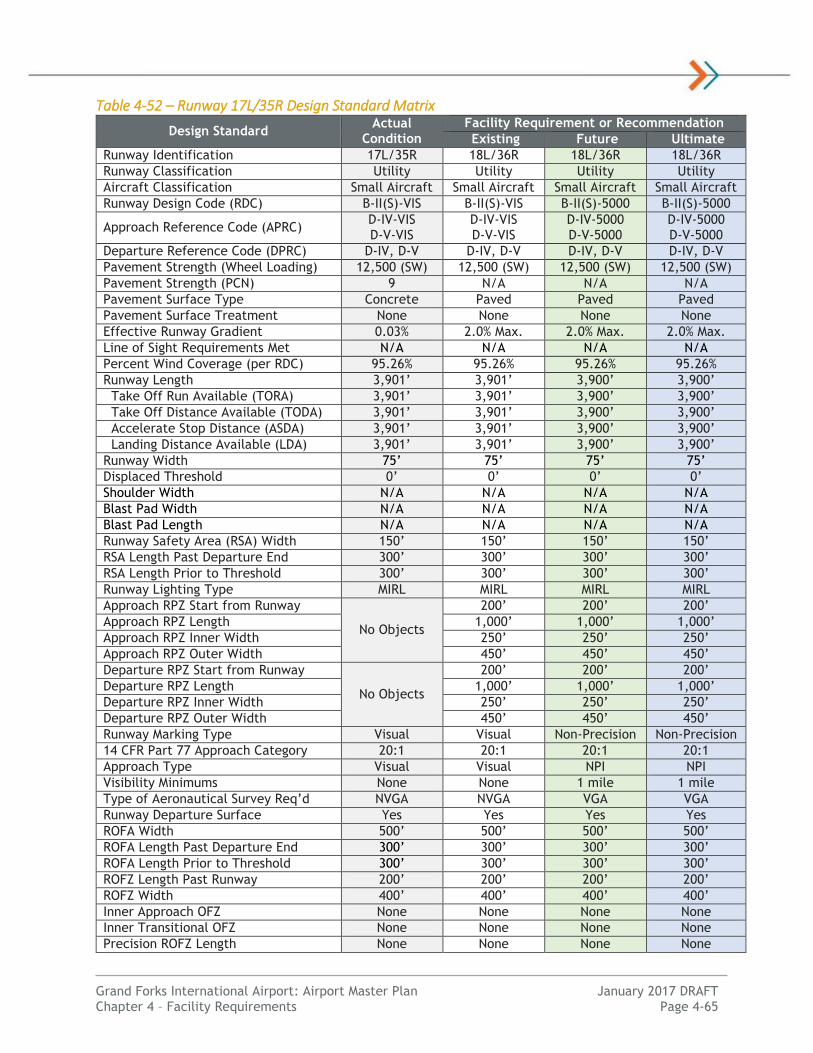
Grand Forks International Airport: Airport Master Plan January 2017 DRAFT Chapter 4 – Facility Requirements Page 4-65
Table 4-52 – Runway 17L/35R Design Standard Matrix
Design Standard Actual
Condition
Facility Requirement or Recommendation
Existing Future Ultimate
Runway Identification 17L/35R 18L/36R 18L/36R 18L/36R
Runway Classification Utility Utility Utility Utility
Aircraft Classification Small Aircraft Small Aircraft Small Aircraft Small Aircraft
Runway Design Code (RDC) B-II(S)-VIS B-II(S)-VIS B-II(S)-5000 B-II(S)-5000
Approach Reference Code (APRC) D-IV-VIS D-V-VIS
D-IV-VIS D-V-VIS
D-IV-5000 D-V-5000
D-IV-5000 D-V-5000
Departure Reference Code (DPRC) D-IV, D-V D-IV, D-V D-IV, D-V D-IV, D-V
Pavement Strength (Wheel Loading) 12,500 (SW) 12,500 (SW) 12,500 (SW) 12,500 (SW)
Pavement Strength (PCN) 9 N/A N/A N/A
Pavement Surface Type Concrete Paved Paved Paved
Pavement Surface Treatment None None None None
Effective Runway Gradient 0.03% 2.0% Max. 2.0% Max. 2.0% Max.
Line of Sight Requirements Met N/A N/A N/A N/A
Percent Wind Coverage (per RDC) 95.26% 95.26% 95.26% 95.26%
Runway Length 3,901’ 3,901’ 3,900’ 3,900’
Take Off Run Available (TORA) 3,901’ 3,901’ 3,900’ 3,900’
Take Off Distance Available (TODA) 3,901’ 3,901’ 3,900’ 3,900’
Accelerate Stop Distance (ASDA) 3,901’ 3,901’ 3,900’ 3,900’
Landing Distance Available (LDA) 3,901’ 3,901’ 3,900’ 3,900’
Runway Width 75’ 75’ 75’ 75’
Displaced Threshold 0’ 0’ 0’ 0’
Shoulder Width N/A N/A N/A N/A
Blast Pad Width N/A N/A N/A N/A
Blast Pad Length N/A N/A N/A N/A
Runway Safety Area (RSA) Width 150’ 150’ 150’ 150’
RSA Length Past Departure End 300’ 300’ 300’ 300’
RSA Length Prior to Threshold 300’ 300’ 300’ 300’
Runway Lighting Type MIRL MIRL MIRL MIRL
Approach RPZ Start from Runway
No Objects
200’ 200’ 200’
Approach RPZ Length 1,000’ 1,000’ 1,000’
Approach RPZ Inner Width 250’ 250’ 250’
Approach RPZ Outer Width 450’ 450’ 450’
Departure RPZ Start from Runway
No Objects
200’ 200’ 200’
Departure RPZ Length 1,000’ 1,000’ 1,000’
Departure RPZ Inner Width 250’ 250’ 250’
Departure RPZ Outer Width 450’ 450’ 450’
Runway Marking Type Visual Visual Non-Precision Non-Precision
14 CFR Part 77 Approach Category 20:1 20:1 20:1 20:1
Approach Type Visual Visual NPI NPI
Visibility Minimums None None 1 mile 1 mile
Type of Aeronautical Survey Req’d NVGA NVGA VGA VGA
Runway Departure Surface Yes Yes Yes Yes
ROFA Width 500’ 500’ 500’ 500’
ROFA Length Past Departure End 300’ 300’ 300’ 300’
ROFA Length Prior to Threshold 300’ 300’ 300’ 300’
ROFZ Length Past Runway 200’ 200’ 200’ 200’
ROFZ Width 400’ 400’ 400’ 400’
Inner Approach OFZ None None None None
Inner Transitional OFZ None None None None
Precision ROFZ Length None None None None
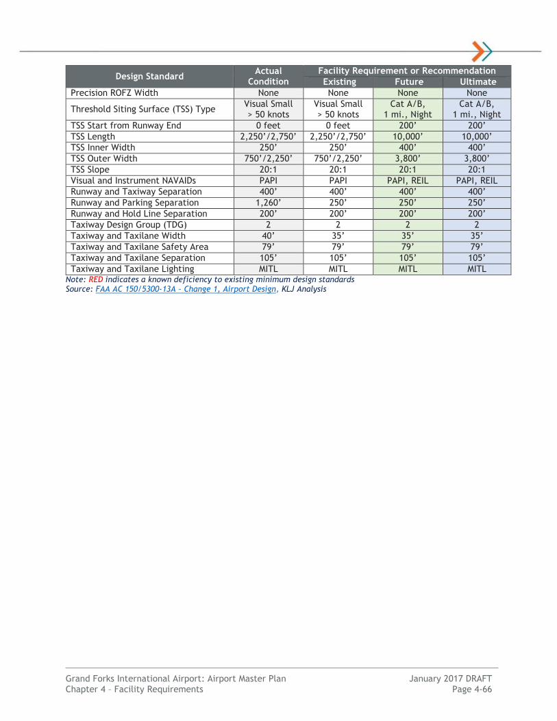
Grand Forks International Airport: Airport Master Plan January 2017 DRAFT Chapter 4 – Facility Requirements Page 4-66
Design Standard Actual
Condition
Facility Requirement or Recommendation
Existing Future Ultimate
Precision ROFZ Width None None None None
Threshold Siting Surface (TSS) Type Visual Small > 50 knots
Visual Small > 50 knots
Cat A/B, 1 mi., Night
Cat A/B, 1 mi., Night
TSS Start from Runway End 0 feet 0 feet 200’ 200’
TSS Length 2,250’/2,750’ 2,250’/2,750’ 10,000’ 10,000’
TSS Inner Width 250’ 250’ 400’ 400’
TSS Outer Width 750’/2,250’ 750’/2,250’ 3,800’ 3,800’
TSS Slope 20:1 20:1 20:1 20:1
Visual and Instrument NAVAIDs PAPI PAPI PAPI, REIL PAPI, REIL
Runway and Taxiway Separation 400’ 400’ 400’ 400’
Runway and Parking Separation 1,260’ 250’ 250’ 250’
Runway and Hold Line Separation 200’ 200’ 200’ 200’
Taxiway Design Group (TDG) 2 2 2 2
Taxiway and Taxilane Width 40’ 35’ 35’ 35’
Taxiway and Taxilane Safety Area 79’ 79’ 79’ 79’
Taxiway and Taxilane Separation 105’ 105’ 105’ 105’
Taxiway and Taxilane Lighting MITL MITL MITL MITL Note: RED indicates a known deficiency to existing minimum design standards Source: FAA AC 150/5300-13A – Change 1, Airport Design, KLJ Analysis

Grand Forks International Airport: Airport Master Plan January 2017 DRAFT Chapter 4 – Facility Requirements Page 4-67
Table 4-53 – Runway 9L/27R Design Standard Matrix
Design Standard Actual
Condition
Facility Requirement or Recommendation
Existing Future Ultimate
Runway Identification 9L/27R 9L/27R 9L/27R 9L/27R
Runway Classification Other-Than-Utility Other-Than-Utility Other-Than-Utility Other-Than-Utility
Aircraft Classification Large Aircraft Large Aircraft Large Aircraft Large Aircraft
Runway Design Code (RDC) B-II-5000 B-II-5000 C-III-5000 (27R) C-III-4000 (9L)
C-III-5000 (27R) C-III-4000 (9L)
Approach Reference Code (APRC) D-IV-5000 D-V-5000
D-IV-5000 D-V-5000
D-IV-5000 D-V-5000
D-IV-5000 D-V-5000
Departure Reference Code (DPRC) D-IV, D-V D-IV, D-V D-IV, D-V D-IV, D-V
Pavement Strength (Wheel Loading) 95,000 (DW) 30,000 (DW) 84,500 (DW) 172,000 (DW)
Pavement Strength (PCN) 28 N/A 26 51
Pavement Surface Type Concrete Paved Paved Paved
Pavement Surface Treatment Grooved None Grooved Grooved
Effective Runway Gradient 0.03% 2.0% Max. 2.0% Max. 2.0% Max.
Line of Sight Requirements Met Yes Yes Yes Yes
Percent Wind Coverage (per RDC) 84.36% 84.36% 92.57% 92.57%
Runway Length 4,206’ 4,206’ 6,800’ 6,800’
Take Off Run Available (TORA) 4,206’ 4,206’ 6,800’ 6,800’
Take Off Distance Available (TODA) 4,206’ 4,206’ 6,800’ 6,800’
Accelerate Stop Distance (ASDA) 4,206’ 4,206’ 6,800’ 6,800’
Landing Distance Available (LDA) 4,206’ 4,206’ 6,800’ 6,800’
Runway Width 100’ 100’ 100’ 150’
Displaced Threshold 0’ 0’ 0’ 0’
Shoulder Width 0’ 0’ 20’ (Rec’d) 25’ (Rec’d)
Blast Pad Width 0’ 0’ 140’ (Rec’d) 200’ (Rec’d)
Blast Pad Length 0’ 0’ 200’ (Rec’d) 200’ (Rec’d)
Runway Safety Area (RSA) Width 150’ 150’ 500’ 500’
RSA Length Past Departure End 300’ 300’ 1,000’ 1,000’
RSA Length Prior to Threshold 300’ 300’ 600’ 600’
Runway Lighting Type MIRL MIRL MIRL MIRL
Approach RPZ Start from Runway
No Objects
200’ 200’ 200’
Approach RPZ Length 1,000’ 1,700’ 1,700’
Approach RPZ Inner Width 250’ 1,000’ 1,000’
Approach RPZ Outer Width 450’ 1,510’ 1,510’
Departure RPZ Start from Runway
No Objects
200’ 200’ 200’
Departure RPZ Length 1,000’ 1,700’ 1,700’
Departure RPZ Inner Width 250’ 500’ 500’
Departure RPZ Outer Width 450’ 1,010’ 1,010’
Runway Marking Type Non-Precision Non-Precision Non-Precision Non-Precision
14 CFR Part 77 Approach Category 34:1 34:1 34:1 34:1
Approach Type NPI NPI NPI NPI
Visibility Minimums 1 mile 1 mile ¾ mile ¾ mile
Type of Aeronautical Survey Req’d VGA VGA VGA VGA
Runway Departure Surface Yes Yes Yes Yes
ROFA Width 500’ 500’ 800’ 800’
ROFA Length Past Departure End 300’ 300’ 1,000’ 1,000’
ROFA Length Prior to Threshold 300’ 300’ 600’ 600’
ROFZ Length Past Runway 200’ 200’ 200’ 200’
ROFZ Width 400’ 400’ 400’ 400’
Inner Approach OFZ None None No Yes
Inner Transitional OFZ None None No Yes

Grand Forks International Airport: Airport Master Plan January 2017 DRAFT Chapter 4 – Facility Requirements Page 4-68
Design Standard Actual
Condition
Facility Requirement or Recommendation
Existing Future Ultimate
Precision ROFZ Length None None None None
Precision ROFZ Width None None None None
Threshold Siting Surface (TSS) Type Cat A/B,
1 mi., Night Cat A/B,
1 mi., Night >Cat B or ¾ mi., Night
>Cat B or ¾ mi., Night
TSS Start from Runway End 200’ 200’ 200’ 200’
TSS Length 10,000’ 10,000’ 10,000’ 10,000’
TSS Inner Width 400’ 400’ 800’ 800’
TSS Outer Width 3,800’ 3,800’ 3,800’ 3,800’
TSS Slope 20:1 20:1 20:1 20:1
Visual and Instrument NAVAIDs PAPI (9L),
VASI/REIL (27R) PAPI, REIL PAPI, REIL
PAPI, REIL, MALSF (9L)
Runway and Taxiway Separation 400’ 400’ 400’ 400’
Runway and Parking Separation 715’ 250’ 500’ 500’
Runway and Hold Line Separation 200’ 200’ 250’ 250’
Taxiway Design Group (TDG) 3 2 3 3
Taxiway and Taxilane Width 50’ 35’ 50’ 50’
Taxiway and Taxilane Safety Area 79’ 79’ 118’ 118’
Taxiway and Taxilane Separation 105’ 105’ 152’ 152’
Taxiway and Taxilane Lighting MITL MITL MITL MITL Note: RED indicates a known deficiency to existing minimum design standards Source: FAA AC 150/5300-13A – Change 1, Airport Design, KLJ Analysis

Grand Forks International Airport: Airport Master Plan January 2017 DRAFT Chapter 4 – Facility Requirements Page 4-69
Table 4-54 – Runway 9R/27L Design Standard Matrix
Design Standard Actual Condition
Facility Requirement or Recommendation
Existing, Future & Ultimate
Runway Identification 9R-27L 9R-27L
Runway Classification Utility Utility
Aircraft Classification Small Aircraft Small Aircraft
Runway Design Code (RDC) B-I(S)-VIS B-I(S)-VIS
Approach Reference Code (APRC) D-IV-VIS D-V-VIS
D-IV-VIS D-V-VIS
Departure Reference Code (DPRC) D-IV, D-V D-IV, D-V
Pavement Strength (Wheel Loading) 12,500 (SW) 12,500 (SW)
Pavement Strength (PCN) 10 N/A
Pavement Surface Type Concrete Paved
Pavement Surface Treatment None None
Effective Runway Gradient 0.01% 2.0% Max.
Line of Sight Requirements Met N/A N/A
Percent Wind Coverage (per RDC) 76.82% 76.82%
Runway Length 3,300’ 3,300’
Take Off Run Available (TORA) 3,300’ 3,300’
Take Off Distance Available (TODA) 3,300’ 3,300’
Accelerate Stop Distance (ASDA) 3,300’ 3,300’
Landing Distance Available (LDA) 3,300’ 3,300’
Runway Width 60’ 60’
Displaced Threshold 0’ 0’
Shoulder Width N/A N/A
Blast Pad Width N/A N/A
Blast Pad Length N/A N/A
Runway Safety Area (RSA) Width 120’ 120’
RSA Length Past Departure End 240’ 240’
RSA Length Prior to Threshold 240’ 240’
Runway Lighting Type MIRL MIRL
Approach RPZ Start from Runway
No Objects
200’
Approach RPZ Length 1,000’
Approach RPZ Inner Width 250’
Approach RPZ Outer Width 450’
Departure RPZ Start from Runway
No Objects
200’
Departure RPZ Length 1,000’
Departure RPZ Inner Width 250’
Departure RPZ Outer Width 450’
Runway Marking Type Visual Visual
14 CFR Part 77 Approach Category 20:1 20:1
Approach Type Visual Visual
Visibility Minimums None None
Type of Aeronautical Survey Req’d NVGA NVGA
Runway Departure Surface Yes Yes
ROFA Width 250’ 250’
ROFA Length Past Departure End 240’ 240’
ROFA Length Prior to Threshold 240’ 240’
ROFZ Length Past Runway 200’ 200’
ROFZ Width 250’ 250’
Inner Approach OFZ None None
Inner Transitional OFZ None None

Grand Forks International Airport: Airport Master Plan January 2017 DRAFT Chapter 4 – Facility Requirements Page 4-70
Design Standard Actual Condition
Facility Requirement or Recommendation
Existing, Future & Ultimate
Precision ROFZ Length None None
Precision ROFZ Width None None
Threshold Siting Surface (TSS) Type Visual Small > 50 knots
Visual Small > 50 knots
TSS Start from Runway End 0 feet 0 feet
TSS Length 2,250’/2,750’ 2,250’/2,750’
TSS Inner Width 250’ 250’
TSS Outer Width 750’/2,250’ 750’/2,250’
TSS Slope 20:1 20:1
Visual and Instrument NAVAIDs PAPI PAPI
Runway and Taxiway Separation 400’ 400’
Runway and Parking Separation 3,220’ 125’
Runway and Hold Line Separation 200’ 125’
Taxiway Design Group (TDG) 1A 1A
Taxiway and Taxilane Width 25’ 25’
Taxiway and Taxilane Safety Area 79’ 79’
Taxiway and Taxilane Separation 105’ 105’
Taxiway and Taxilane Lighting MITL MITL Note: RED indicates a known deficiency to existing minimum design standards Source: FAA AC 150/5300-13A – Change 1, Airport Design, KLJ Analysis

Grand Forks International Airport: Airport Master Plan January 2017 DRAFT Chapter 4 – Facility Requirements Page 4-71
Passenger Terminal
Background
The requirements identified for the passenger terminal are identified to accommodate the travelling public with a sufficient level of service based on existing and projected growth. Since the last Airport Master Plan (2008), GFK constructed a new airport passenger terminal located directly south of the existing Fixed-Base Operator (FBO) in 2012, as well as a new apron space for air carrier aircraft. GFK also demolished the old passenger terminal building.
The existing passenger terminal building has two gates and three aircraft parking positions. In total, the passenger terminal building is comprised of approximately 50,000 square feet. Approximately 40,000 SF of space utilized for moving people and baggage as well as security. The remaining space is for airline, administration, mechanical and storage use.
This section will identify key issues with the existing passenger terminal building and provide planning-level conceptual planning and space requirements. Landside requirements for passenger loading & unloading and automobile parking are evaluated separately. Requirements identified as based on the following references to FAA, Transportation Security Administration (TSA), and International Air Transport Association (IATA) and industry standards:
FAA AC 150/5360-13A, Planning and Design Guidelines for Airport Terminal Facilities (2012)
Airports Cooperative Research Program (ACRP), Report 25: Airport Passenger Terminal Planning and Design Guidebook (2010)
The object of this section is to evaluate overall space needs compared to existing and future demand requirements. Alternatives addressing how needs will be fulfilled will be developed and presented in Chapter 5: Alternatives Analysis. Broad recommendations will be made in this study; details on a specific engineering and architectural review would be completed in a separate study.
Terminal Design
OVERALL CONSIDERATIONS
Terminals are designed to handle passenger volume and functions to interface between aircraft and ground transportation. Terminals must accommodate changes in the airline industry and passenger preferences. Factors that influence terminal design include:
Total Passenger Volume: The annual number of passenger enplanements affects the total size and recommended configuration of a terminal building.
Passenger Peaking Characteristics: Arriving or departing flights concentrated into a small timeframe require adequate space and throughput for surges in passenger ticketing, security, gates, baggage claim and concessions.
Passenger Preferences: Business travelers typically are more experienced with airports, demand shorter wait times and efficiency. Leisure passengers require more time, attract meters/greeters and typically have more baggage to process. Airline fees also drive passenger preferences to check or carry-on baggage.
Airline Station Characteristics: A spoke airport such as GFK has destinations as airline hubs. Spoke airports accommodate origin & destination (O&D) passengers rather than those using GFK to connect to another flight. Aircraft tend to remain overnight for the first flight out to a hub airport. Passengers have a requirement for check-in, security, baggage and parking.
Aircraft Mix: The size and frequency of the aircraft affects the number and size of the gates, passenger waiting holdroom and the terminal apron configuration.

Grand Forks International Airport: Airport Master Plan January 2017 DRAFT Chapter 4 – Facility Requirements Page 4-72
International Service: Airports with international service require aircraft to have longer gate occupancy times and additional space for Federal Inspection Services (FIS)
Industry Trends: Industry changes are affecting terminal design. Examples include reduced airline flight frequency, higher load factors, evolving aircraft types, use of check-in kiosks, TSA pre-check program and airline baggage fees.
LEVEL OF SERVICE
Terminal improvements are evaluated in their ability to serve passengers and provide a comfortable experience through the airport. A Level Of Service (LOS) concept uses a set of standards to measure the quality of the passenger experience. LOS standards are used to evaluate the efficiency of passenger flow, space requirements and wait time. Each LOS has a defined space planning standard to determine facility requirements as identified in Table 4-55.
Table 4-55 – Level of Service (LOS) Standards LOS Service Level
Excellent (A) Conditions of free flow; no delays; direct routes; excellent level of
comfort
High (B) Condition of stable flow; high level of comfort
Good (C) Condition of stable flow; provides acceptable throughput; related
systems in balance
Adequate (D) Condition of unstable flow; delays for passengers; condition
acceptable for short periods of time
Unacceptable (E) Condition of unstable flow; subsystems not in balance; represents
limiting capacity in the system
System Breakdown (F) Unacceptable congestion and delays Source: ACRP Report 25: Airport Passenger Terminal Planning and Design
The assumption for this master plan is to obtain LOS C which peak wait times are 10 minutes or below. Delays and space requirements are typically considered acceptable. LOS C is considered reasonable balance between ideal size and economic considerations.
AIRPORT CONSIDERATIONS
There are a few specific items that need to be addressed in this study for GFK. Based on conversations with airport management, the holding room space has a tendency to be at maximum capacity. During peak hours/times, when two flights are waiting to board, passengers can sometimes be required to stand because sufficient seating is not available. This is especially true with an outbound Allegiant flight and outbound Delta flight are waiting to board, but also when aircraft are deplaning while other flights are waiting to depart. This study needs to evaluate holding room space needs and the ability to expand from the current configuration. Generally speaking the terminal was designed to handle 50-seat regional jet aircraft, not regular service from larger narrowbody aircraft.
A second item that needs to be evaluated are the gate positions for parked aircraft. With three current positions and two gates (one swinging between two aircraft parking positions), there are a limited number of parking positions available for aircraft. If one aircraft has maintenance issues and is unable to move, or poor weather forces aircraft to divert or stay at the gate, space would run out for aircraft to deplane/enplane through the terminal building. This especially holds true for public aircraft charters that operate from the passenger terminal such as Sun Country Airlines to Laughlin, NV.
Demand Factors
The primary function of a terminal is to provide adequate space to serve passengers. An evaluation of the passenger and gate demand is first completed to provide overall terminal space planning metrics at GFK.

Grand Forks International Airport: Airport Master Plan January 2017 DRAFT Chapter 4 – Facility Requirements Page 4-73
PASSENGER ACTIVITY LEVELS
Planning activity levels (PAL) numbers in Table 4-56 are to be used for terminal building planning. These figures provide an estimate of the number of passengers to arrive, depart and generally flow through the terminal building. The figures are based on a percentage of total enplaned passengers the existing airline schedule. No surge factor is provided for irregular operations.
Table 4-56 – Terminal Passenger Activity Levels Metric Base PAL 1 PAL 2 PAL 3 PAL 4
Terminal Passengers
Annual Enplanements 146,531 147,612 170,763 194,170 220,787
Design Hour Departing 192 193 223 254 289
Design Hour Arriving 192 193 223 254 289
Design Hour Total 363 366 423 481 547 Source: KLJ Analysis
DESIGN HOUR FLEET MIX
The aircraft fleet mix in the terminal area is determined using the total number of forecast departures as shown during the design hour. The design hour operations occur at two points daily when a Delta and Allegiant flight arrive and depart within the same hour.
Design hour aircraft types are grouped in Airplane Design Group (ADG) and class as seen in Table 4-57. The design aircraft for GFK will evolve to become a narrowbody, ADG-III aircraft accommodating up to 177 passengers. The aviation forecasts project the average number of seats per aircraft will increase from 73.6 to 101.9. As a result, the total number of flights is projected to increase 7 percent whereas the total number of passengers will increase by over 50 percent through PAL 4.
Table 4-57 – Design Hour Departures Design Aircraft Seats Base PAL 1 PAL 2 PAL 3 PAL 4
Medium Regional Aircraft (ADG-II) 50 1.57 0.74 0.27 0.00 0.00
Large Regional Aircraft (ADG II/III) 65-99 0.14 0.72 1.03 1.49 1.44
Narrowbody Aircraft (ADG-III) 110-177 0.36 0.38 0.52 0.54 0.79
Boeing 757 (ADG-IV) 181-215 0.03 0.01 0.01 0.00 0.00
Design Hour Departures - 2.1 1.9 1.8 2.0 2.2 Source: KLJ Analysis
GATE REQUIREMENTS
Gates are necessary for aircraft to adequately serve arriving and departing aircraft. The minimum number of gates at an airport is a function of the peak hour activity. Additional contingency metrics are also used to determine the required gates.
GFK has three existing gates, two with passenger boarding bridges. The south boarding bridge swings between Gate 2A and 2B but cannot simultaneously deplane/enplane passengers from both gates. The north boarding bridge allows for one aircraft to deplane/enplane from Gate 1 independently.
Currently the airport typically experiences peak departures/gate demand on Mondays and Wednesdays during late morning hours when an Allegiant and Delta flight arrive and depart within the same hour. Gate congestion also occurs when Delta parks up to two aircraft overnight and during irregular operations. There is a need for independent use of the third gate with a passenger boarding bridge for operational flexibility. Outdoor enplaning and deplaning of passengers is not recommended in a colder climate like as Grand Forks.
Table 4-58 summarizes the total GFK gate needs.

Grand Forks International Airport: Airport Master Plan January 2017 DRAFT Chapter 4 – Facility Requirements Page 4-74
Table 4-58 – Gate Requirements Design Aircraft Existing Base PAL 1 PAL 2 PAL 3 PAL 4
Design Hour Departures 2.1 2.1 1.9 1.8 2.0 2.2
Contingency Gate 0 1 1 1 1 1
Total Gates 3* 3.1 2.9 2.8 3.0 3.2
Total Required Gates 3 3 3 3 3 3
Total Boarding Bridges 2 3 3 3 3 3 Source: KLJ Analysis; *One gate not available for independent use with a passenger boarding bridge
The total required gates is then split up into aircraft types using the fleet mix determinations to determine the total and equivalent number of gates for space planning. See Table 4-59.
Table 4-59 – Gate Space Requirements
Design Aircraft Existing/
Base PAL 1 PAL 2 PAL 3 PAL 4
Medium Regional Aircraft (ADG-II) 1* 0 0 0 0
Large Regional Aircraft (ADG-III) 1 1 1 1 1
Narrowbody Aircraft (ADG-III) 0 1 1 1 1
Boeing 757 (ADG-IV) 1 1 1 1 1
Total Number of Gates 3 3 3 3 3
Narrowbody Equivalent Gate (NBEG) 1.6 1.6 1.8 2.0 2.2
Equivalent Aircraft (EQA) 1.1 1.1 1.2 1.3 1.5 Source: KLJ Analysis; *One gate not available for independent use with a passenger boarding bridge
Although GFK has three gates, there are only two gates with passenger boarding bridges to accommodate enplanements and deplaning. The existing Gate 2A is capable of accommodating large regional aircraft with Gate 2B able to accommodate a medium regional aircraft simultaneously. Gate 1 parking space is larger, capable of accommodating up to Boeing 757 (or similar) aircraft. Geometrics are tight.
Limitations in utilizing the existing three aircraft parking spaces are noticed during peak hours, maintenance issues, or any irregular operations that may arise. As such, it is recommended in PAL 1 the airport plan to upgrade a gate to accommodate narrowbody aircraft with an optional additional boarding bridge to the terminal area for irregular operations (IROPs). This contingency gate would accommodate miscellaneous parking needs including maintenance issues, crew issues, overnight parking, weather delays and aircraft charters wishing to use a gate. This gate should be sized for Boeing 757 aircraft is possible.
By PAL 4 it is anticipated that a large regional, a narrowbody and Boeing 757 gate will be needed to accommodate increased design hour demand with contingencies. More than three gates may be needed beyond the planning period.
Building Areas
Individual functional areas of the terminal building have been evaluated to determine planning-level space needs to accommodate current and future demand. Space requirements will be a major consideration when evaluating terminal building development alternatives.
AIRLINE SPACE
There is approximately 1,500 SF of existing space behind the ticketing counters dedicated for the airline administration and operations offices. There is one dedicated airline using the space (Delta) and occupies approximately half of the available airline space. This space consists of a manager’s office, operations room, break room, and training supplies/locker room. The remaining space is a blank shell available for an additional airline to have an office space. Allegiant does not require office space in the

Grand Forks International Airport: Airport Master Plan January 2017 DRAFT Chapter 4 – Facility Requirements Page 4-75
main terminal area. Assuming each airline requires 600 SF of space, there is adequate space for airline management and circulation for up to two airlines/service providers at GFK.
Baggage Service Offices (BSO) provide handling and storage for late or unclaimed bags. GFK does not have an existing space dedicated to BSO facilities. A 300 SF BSO near the baggage claim area should be considered if the terminal building is upgraded in the long-term.
Other airline space considerations include airline ramp offices and support facilities on the airside portion of the airport. These are used for airline ground servicing functions. Dedicated offices are not available at GFK; the airline office near ticketing serves this function. Ground Storage Equipment (GSE) is parked outdoors in dedicated areas of the apron, or in a 900 SF area on the back side of the baggage handling area. These areas are generally considered to be adequate for two airline operations. Additional space would be needed for three airlines in the long-term.
Table 4-60 summarizes the airline space requirements.
Table 4-60 – Airline Space Requirements Metric Existing Base PAL 1 PAL 2 PAL 3 PAL 4
Number of Airlines 2 2 2 2 3 3
Airline Office Space 1,500 1,200 1,200 1,200 1,800 1,800
Ramp Offices/Services 0 0 0 0 0 0
Baggage Service Office 0 300 300 300 300 300 Source: KLJ Analysis
TICKETING & CHECK-IN
The passenger check-in process continues to change as new technologies and processes are implemented. These changes have reduced the space needed in the ticketing lobby space and staffed ticket counter positions. Waiting times are also reduced. Traditionally, all passengers checked in at the ticket counter to both receive boarding passes and check baggage. Remote self-service equipment now allows individuals to obtain boarding passes online or at the airport without the need to use staffed ticket counters. Checked baggage is accommodated by a dedicated airline bag-drop representative at the counter. The use of self-service equipment continues to grow. Potential future trends include self-tagging stations and remote off-airport bag-drop facilities which would reduce the need to have staffed positions at the airport.
The passenger check-in assumptions are important to evaluate space and facility needs. For planning purposes, the following assumptions are made:
Passengers Checking Baggage: Average is 50 percent, 70 percent for leisure flights
Checked Baggage Location: 100 percent within the terminal
Passenger Check-In Location: 10 percent remote, 30 percent in-terminal kiosk, 60 percent in-terminal counter
The ticketing lobby in front of the ATO offices consists of approximately 2,600 SF of space and is located on the north end of the terminal building. When passengers enter the terminal, ticket counters are located directly across from the vestibule used to enter the building. Delta currently has five self-serve electronic kiosks located at the beginning of the passenger check-in lines. Eight staffed podiums (four podium locations with 2 monitors per podium) are available for passenger check-ins. The specific staffing levels are based on airline operations. Allegiant Airlines does not currently provide self-service kiosks for passenger check-ins.
At this time and through the foreseeable future, ticket kiosks and ticket space is adequate as summarized in Table 4-61. Based on the number of passengers using the terminal and peak hour demand, passenger queuing has not been an issue. In the future, additional passenger queuing may be needed to better funnel the passenger check-in process and preserve a circulation corridor.

Grand Forks International Airport: Airport Master Plan January 2017 DRAFT Chapter 4 – Facility Requirements Page 4-76
Table 4-61 – Ticketing Requirements Metric Existing Base PAL 1 PAL 2 PAL 3 PAL 4
Ticketing Positions 8 3 4 4 4 5
Bag Drops 0 1 1 1 1 1
Number of Dedicated Kiosks 5 2 2 2 2 2
Total Equivalent Positions 13 6 7 7 7 8
Total Ticketing Area (SF) 2,600 1,800 2,100 2,100 2,100 2,400 Source: KLJ Analysis
BAGGAGE SCREENING
Baggage screening is located directly behind the southern portion of the ticket podium area. This area and associated equipment are operated by the Transportation Security Administration (TSA) to screen airline baggage prior to being loaded onto the aircraft. This area houses one in-line baggage screening system, as well as tables, chairs, and office equipment used by the TSA for baggage processing. Bags are fed into this room via a bag belt directly behind the ticket counters. Cleared bags are sent to the baggage make-up facility as one integrated baggage system.
At GFK the baggage screening room is approximately 1,101 SF in size with one Explosive Detection System (EDS) machines to screen baggage. Secondary screening requires an on-screen resolution (OSR) by TSA personnel. If hand inspection is required, workstations are provided to further inspect bags using Explosive Trace Detection (ETD) machines.
The current in-line system is assumed to process 200 bags per hour with 70 percent of passengers checking an average of one bag. As summarized in Table 4-62, calculations recommended a second EDS machine by PAL 2 to process peak passenger baggage. Additional space is recommended for this action. Actual decisions to upgrade equipment will be made by TSA.
Table 4-62 – Baggage Screening Requirements Metric Existing Base PAL 1 PAL 2 PAL 3 PAL 4
Baggage Screening Area 1,100 940 940 1,740 1,740 1,740
Required EDS Units 1 1 1 2 2 2
Required OSR Screening Areas 1 1 1 1 1 1
Required ETD Workstations 3 1 1 1 1 1 Source: KLJ Analysis
BAGGAGE MAKE-UP
Baggage make-up facilities are located on the west half of the first floor of the terminal building. The existing baggage make-up area has approximately 2,300 SF of usable space. After security screening, bags are loaded onto a single carousel (sterile-side) and loaded by ground handlers for proper loading onto respective aircraft. Based on the interviews conducted of airline personnel, the existing layout is conducive for one airline processing bags. The existing layout only allows a few bag carts at a time to load bags, and can only load on one side of the carousel. Only one side of the circular carousel can be accessed by baggage carts.
Ideally, each airline would have their own carousel for loading bags and sorting. Because Allegiant and Delta process bags with separate ground crews, each airline must take their turn in front of the carousel. Space recommendations are based on two simultaneous aircraft with two narrowbody aircraft in PAL 4. Additional space for the baggage-make up area is recommended as summarized in Table 4-63.
Table 4-63 – Baggage Make-Up Requirements Metric Existing Base PAL 1 PAL 2 PAL 3 PAL 4
Baggage Make-Up Area 2,300 3,000 3,000 3,000 3,000 4,000 Source: KLJ Analysis

Grand Forks International Airport: Airport Master Plan January 2017 DRAFT Chapter 4 – Facility Requirements Page 4-77
SECURITY CHECKPOINT
The Security Screening Checkpoint (SSCP) area is used by TSA to screen passengers and property prior to entering the sterile area of the terminal concourse.
TSA staff at GFK processes passengers on the second floor. There is a total of 2,550 SF of space dedicated to staging and processing passengers and their baggage for security screening, including a 10-foot deep passenger reconciliation area. The TSA queuing space is 900 SF of the space and is typically full of passengers during peak operating hours. There is one main and one TSA Pre-Check queuing line that funnels into the TSA screening area.
The TSA screening area is 1,425 SF of space and has two lanes for baggage screening and passenger screening. There is one walk-through metal detector that services both baggage screening lanes. Based on passenger demand, one of these lanes can be used solely for TSA Pre-Check and one is used for other passengers. In previous years, GFK’s TSA screening area did have one Advanced Image Technology (AIT) whole body scanner but was relocated to a different airport based on passenger demand.
The TSA office space is approximately 1,000 SF, is located directly north of the TSA screening facilities, and has an attached conference room for TSA use. Deplaning passengers exit through a double-door exit lane directly south of the TSA screening area. The doors are controlled automatically and do not allow passengers to walk back into the waiting area.
Throughput calculations of passengers at GFK were calculated using the ACRP 25 Terminal Planning Spreadsheet with basic assumptions:
Throughput rate of 150 passengers per hour per lane
Peak 30-minute originating passengers from check-in was calculated at half of the peak-hour demand for each PAL
Maximum wait time goal to be achieved is 10 minutes
Security screening checkpoint requirements are summarized in Table 4-64. The existing checkpoint is short of total recommended space needs in the long-term. It is anticipated GFK will require a third lane to process passengers by PAL 4 to meet peak demands and desired level of service. Without a third screening lane queue times are modeled to approach 12 minutes by PAL 4. As a result, additional space will be needed for the checkpoint. It is recommended GFK plan for possible TSA expansion options for processing passengers. Additional queuing and processing space may also be needed to dedicate to the TSA Pre-Check program which is not accounted for in the calculations.
Total percentage of passengers bring carry-on bags can reduce the throughput of passengers through the checkpoint, thus increasing security lines and space needs. Continued coordination with local TSA staff is highly recommended to monitor throughput rates.
Table 4-64 – Security Screening Checkpoint Requirements Metric Existing Base PAL 1 PAL 2 PAL 3 PAL 4
Security Screening Lanes 2 2 2 2 2 3
Maximum Wait Time (min.) - 1.1 1.3 4.6 7.9 1.1
Security Queue Area 900 900 900 900 900 1,350
Total Security Area 2,550 2,550 2,550 2,550 2,550 3,825 Source: KLJ Analysis
However, technology and processes will continue to evolve, and equipment size/location recommendations will change as technology progresses. Adding a TSA Pre-Check lane will increase efficiencies in processing both pre-check and regular passengers, but requires additional dedicated queuing space not modeled. GFK recently implemented a pre-check lane in 2016. The analysis above assumes the two screening lanes are fully staffed and operational.

Grand Forks International Airport: Airport Master Plan January 2017 DRAFT Chapter 4 – Facility Requirements Page 4-78
PASSENGER HOLDROOMS
Passenger holdrooms are designated areas in the sterile concourse area where passengers wait to board the aircraft at the gate. The size of the holdrooms are directly related to the aircraft size at each gate. The estimated fleet mix is used to determine holdroom sizing for each gate.
There is one combined passenger holdroom providing seating for outbound flights at GFK. The total usable area is approximately 4,200 SF to provide seating and amenities for passengers waiting to board their flights. Approximately 180 seats currently provide passenger seating for both gates. When outbound passengers clear the TSA checkpoint area, circulation space is used for passengers to re-group from the screening process. The holdroom area does not include a narrow 10-foot wide circulation corridor. Total usable holdroom depth is approximately 30 feet.
Adjacent to the south side of the holdroom area near Gate 2, there is a 600 SF concession area providing food, beverages, and souvenirs. More recently, a bar area was added in the holdroom and allows approximately 15-20 patrons to sit while waiting for their flight.
It is assumed that 80 percent of the travelers leaving GFK are utilizing the seating area, while 20 percent are choosing to stand. Gate 1 holdroom is assumed to accommodate up to a 177-seat aircraft and Gate 2 is designed for up to 76-seat aircraft. Holdroom size requirements are presented in Table 4-65.
Table 4-65 – Holdroom Requirements Metric Existing Base PAL 1 PAL 2 PAL 3 PAL 4
Design Aircraft
50 passengers (1,200 SF) 0 0 0 0 0 0
76 passengers (1,600 SF) 1 1 1 1 2 1
110 passengers (2,000 SF) 0 0 0 0 0 1
177 passengers (2,900 SF) 1 1 1 1 1 1
215 passengers (3,400 SF) 0 0 0 0 0 1
Total Airline Gates In Use 2 2 2 2 3 3
Total Holdroom Area 4,200 4,100 4,500 4,500 6,100 7,000
Total Required Seats 180 163 182 182 237 289 Source: KLJ Analysis
The existing effective holdroom capacity does not meet the needs of simultaneous 76-passenger and 177-passenger aircraft departures. There are also not enough total seats and space to meet PAL 1 demand needs. The holdroom calculations do not include irregular operations, when additional seating and space is needed.
In PAL 4, it is forecasted three aircraft may need to share the same holdroom space at the same time. From the base scenario, and per the ACRP 25 guidance, the holdroom area is 2,800 SF smaller than recommended guidance. It is recommended the airport plan evaluate holdroom expansion opportunities to react to future changes.
CONCOURSE SIZE & CIRCULATION
The overall size of the terminal concourse was evaluated for future space planning. The exterior terminal frontage is based on the aircraft fleet mix parked at the gate with sufficient wingtip clearance between aircraft. Table 4-66 contains a summary of the calculations.
Grand Forks International Airport: Airport Master Plan January 2017 DRAFT Chapter 4 – Facility Requirements Page 4-79
Table 4-66 – Concourse Size & Requirements Metric Exist. Base PAL 1 PAL 2 PAL 3 PAL 4
Narrowbody Equivalent Gate (NBEG) 2.0 2.7 2.7 3.0 3.0 4.0
Aircraft Frontage (LF) 480 386 386 429 429 572
Circulation Corridor Width (ft.) 10 20 20 20 20 20
Gross Terminal Area Size (SF) 49,995 48,600 48,600 54,000 54,000 72,000 Source: KLJ Analysis
Through a concourse size/circulation capacity analysis per ACRP 25 guidance, the existing concourse width of 165 feet is sized for two medium regional aircraft (CRJ-200) connected to a passenger boarding bridge. A total approximate width of 480 feet is provided for aircraft parking frontage for three aircraft.
Concourse width is not adequately sized to meet demand for three parked aircraft at the gates each with a passenger boarding bridge; one medium regional aircraft (CRJ-200), one large regional aircraft (CRJ-900), and one narrowbody aircraft (Airbus A320). At about PAL 2, when airlines are anticipated to switch equipment to larger regional aircraft, additional width is needed if all three aircraft are to be accommodated at a gate. This will add efficiencies in passenger boarding and to help alleviate terminal congestion.
The scenario in PAL 4 assumes two large regional (CRJ-900 or similar) and two narrowbody (A320) aircraft are parking in front of the concourse. It is determined 572 feet of aircraft parking frontage is required to meet demand through PAL 4. Alternatives should be evaluated to accommodate this recommendation.
The current circulation corridor width is approximately 10 feet located adjacent to the back side of the holdroom area. The recommended minimum width for a circulation corridor for a single-loaded terminal design is 20 feet. Increased terminal concourse depth is needed currently to meet passenger circulation needs.
Using very general planning assumptions of 18,000 SF per narrowbody gate per the ACRP 25 report, the overall terminal building size is recommended to increase to accommodate larger aircraft as demand warrants for three demand-driven gates.
BAGGAGE CLAIM & HANDLING
Baggage claim devices are provided for arriving passengers to retrieve their checked bags from the aircraft. Bags are offloaded from the aircraft, placed on baggage carts, transported to a baggage handling area and then offloaded onto the baggage belts in a secure area.
The baggage claim area is located on the first floor in the southwest corner of the terminal area with 4,000 SF of dedicated. There is one L-shaped flat-plate baggage carousel with approximately 110 LF of exposed frontage for passengers to retrieve their luggage. Roughly 25 LF of this carousel is on the sterile side of the terminal for baggage handlers to process bags of deplaned aircraft. When two aircraft are consecutively deplaning, this configuration can cause congestion issues on the sterile side. Other than the footprint of the baggage carousel, the majority of the baggage claim space is used for passengers waiting for their baggage. It is assumed that roughly 70 percent of deplaning passengers wait for checked bags. Table 4-67 summarizes the baggage claim & handling space needs.
Table 4-67 – Baggage Claim & Handling Requirements Metric Exist. Base PAL 1 PAL 2 PAL 3 PAL 4
Baggage Claim Frontage (LF) 110 77 78 90 102 116
Peak Single Aircraft Frontage (LF) 110 142 142 142 142 142
Total Baggage Claim Area (SF) 4,000 3,550 3,550 3,550 3,550 3,550
Total Baggage Handling Area (SF) 3,000 2,652 2,652 2,652 2,652 2,652 Source: KLJ Analysis

Grand Forks International Airport: Airport Master Plan January 2017 DRAFT Chapter 4 – Facility Requirements Page 4-80
GFK’s existing baggage handling/claim area is determined to be adequately sized (by area) through the planning period. It is recommended, however, the linear footage of available carousel space be lengthened. In the existing conditions, it is determined peak times require 142 LF of baggage carousel frontage. This peak time occurs when the design aircraft (Allegiant’s A320) deplanes. Additional baggage offloading length within the baggage handling area is also recommended during any expansion of the claim device.
Total percentage of passengers checking bags dramatically changes the baggage claim requirements. Baggage trends should continue to be monitored by the airport with space needs updated. Over the past several years, airline fee structures have charged for checked bags reducing demand. The trend is for airlines to charge for carry-on bags as well which may cause the number of checked bags to increase again.
CONCESSIONS
Concessions areas within the airport terminal used for retail space are located in the public and sterile portions of the terminal. Airport industry trends demand more concessions in the sterile portion of the terminal as passengers have increased dwell times after the security checkpoint. Additionally, liquids, aerosols and gels are heavily restricted through the security checkpoint.
One food/beverage concessionaire with nearly 2,000 SF of space operates at GFK with concession space on both the sterile and non-sterile portion of the concourse. Space includes seating area. Amenities include a gift shop, food/sandwiches made from the kitchen, and beverages. In recent years, a bar area was added to the sterile side. Seating is also available on the non-sterile side but does not permit alcohol consumption. Secure locking doors regulate access between the sterile and non-sterile areas and are used by concession staff only.
Vending machines are located on the first floor directly north of the baggage claim area. Vending machines are also located on the second floor hold room and in the greeter’s lobby. Deliveries for concessions are conducted in a secure garage providing access on the south side of the terminal area. There is an elevator directly west of this garage that allows workers to move items upstairs through the secure side of the terminal.
There has not been expressed a need to provide additional retail or food/beverage concession space, however additional space should be considered in the sterile area if the terminal concourse if expanded in the future. Additional space could be made available in the first floor waiting area.
RENTAL CAR
Rental car facilities are conveniently located directly east of the baggage lobby area. Three companies (Enterprise, Avis, Hertz) provide vehicle rental services for GFK and each occupy a 250 SF office. Total rental car space is 1,700 SF which includes service counters and customer queuing space away from the general terminal lobby circulation area. There are no available offices for additional vehicle rental companies. A separate exit provides access to rental vehicle ready/return parking lots immediately adjacent to the terminal building. Tenants are satisfied with the space provided and find the layout to be convenient and easily accessible. Rental car space needs are summarized in Table 4-68.
Table 4-68 – Rental Car Requirements Metric Exist. Base PAL 1 PAL 2 PAL 3 PAL 4
Number of Providers 3 3 3 3 3 4
Rental Car Office Area (SF) 750 675 675 675 675 900
Rental Car Area (SF) 1,700 1,575 1,575 1,575 1,575 2,100 Source: KLJ Analysis
Airports accommodating nearly 500,000 passengers typically accommodate up to four rental car providers. If the terminal building were to be expanded in the future, office to accommodate a fourth rental car provider should be considered.

Grand Forks International Airport: Airport Master Plan January 2017 DRAFT Chapter 4 – Facility Requirements Page 4-81
AIRPORT ADMINISTRATION
GFK has a total of nearly 2,100 SF of airport administration space. The primary Grand Forks Regional Airport Authority offices are located on the second floor with 1,600 SF of space for reception/waiting, four offices and a boardroom. Administration space on the first floor includes a general 500 SF conference room. Space requirements are deemed adequate for the planning period.
There is no dedicated in-terminal space for airport security or Law Enforcement Officer (LEO). A dedicated space is recommended when the terminal is expanded.
PUBLIC SPACES
Public spaces include non-revenue generating areas of the terminal building used for restrooms, circulation, seating and waiting areas. Building systems to support the operations of the terminal include mechanical, electrical and telecommunications spaces.
Public restrooms at GFK are located in a central location within the secure airside area. Additional public restrooms are located in the non-secure landside area on the first and second floors. Within the airside area, there are a total of 10 women’s fixtures and 7 men’s fixtures and one family/unisex restrooms. Restrooms should be sized to accommodate passengers’ carry-on luggage. Female restrooms have an additional 25% fixture factor added to meet some building code requirements. One unisex/family restrooms should also be provided per restroom module. Total restroom fixtures needed were calculated based on ACRP Report 130: Guidebook to Airport Terminal Restroom Planning and Design. Peak hour restroom requirements are summarized in Table 4-69. No additional restroom fixtures are needed to meet PAL 4 demands.
Table 4-69 – Restroom Requirements Metric Exist. Base PAL 1 PAL 2 PAL 3 PAL 4
Airside Secure Area
Male Restrooms 3 2 2 2 2 3
Female Restrooms 5 3 3 3 3 4
Unisex/Family Restrooms 1 1 1 1 1 1
Total Fixtures 9 6 6 6 6 8
Landside Non-Secure Area
Male Restrooms 7 4 4 5 5 6
Female Restrooms 8 5 5 7 7 8
Unisex/Family Restrooms 2 2 2 2 2 2
Total Fixtures 17 11 11 14 14 16 Source: ACRP Report 130, KLJ Analysis
General circulation in the terminal is sufficient with three public entry/exit points. The secure waiting area has a narrow circulation corridor. The existing effective width of this corridor is 10 feet where 20 feet is recommended. Widening the corridor would affect holdrooms space which is already at capacity during peak periods. The overall depth of the concourse should be widened during a future terminal expansion project. Circulation efficiency is a product of good wayfinding signage that exists at GFK.
A 3,400 SF meet/greet lobby is located on the second level adjacent to the exit lane and the security checkpoint. The size of this area is sufficient to meet the needs through the planning period. There is also additional waiting areas located near the south main entrance.
OTHER SPACES
There is a general lack of storage space in the terminal building at GFK. Additional space should be considered during any expansion project. Also, the data/technology room is undersized for the need. Additional secondary space should be considered.

Grand Forks International Airport: Airport Master Plan January 2017 DRAFT Chapter 4 – Facility Requirements Page 4-82
SPACE SUMMARY
Table 4-70 summarizes the identified space requirements for the GFK passenger terminal building.
Table 4-70 – Passenger Terminal Building Space Requirements Metric Exist. Base PAL 1 PAL 2 PAL 3 PAL 4
Demand
Annual Enplanements - 146,531 147,612 170,763 194,170 220,787
Building Areas
Total Required Gates 3 3 3 3 3 3
Total Passenger Boarding Bridges 2 3 3 3 3 4
Airline Ticket Office (SF) 1,500 1,200 1,200 1,800 1,800 1,800
Equivalent Ticketing Positions 13 6 7 7 7 8
Ticketing Area (SF) 2,600 1,800 2,100 2,100 2,100 2,400
Baggage Screening Area (SF) 1,100 940 940 1,740 1,740 1,740
Baggage Makeup Area (SF) 2,300 3,000 3,000 3,000 3,000 4,000
Security Screening Lanes 2 2 2 2 2 4
Total Security Area (SF) 2,550 2,550 2,550 2,550 2,550 3,825
Total Holdroom Area (SF) 4,200 4,500 4,500 4,500 6,100 7,000
Total Holdroom Seats 180 163 182 182 237 289
Aircraft Frontage (LF) 480 386 386 429 429 572
Concourse Circulation Width (SF) 10 20 20 20 20 20
Baggage Claim Frontage (LF) 110 142 142 142 142 142
Baggage Claim Area (SF) 4,000 3,550 3,550 3,550 3,550 3,550
Baggage Handling Area (SF) 3,000 2,300 2,300 2,400 2,500 2,500
Rental Car Area (SF) 1,700 1,575 1,575 1,575 1,575 2,100
Airside Restroom Fixtures 9 6 6 6 6 8
Landside Restroom Fixtures 17 11 11 14 14 16
Gross Terminal Size (SF) 49,995 48,600 48,600 54,000 54,000 72,000 Source: KLJ Analysis
Aircraft Apron
TERMINAL APRON
The primary purpose of the terminal apron is to provide parking for commercial passenger aircraft at the terminal gate and provide circulation space for aircraft and airline support functions. There are two existing Passenger Boarding Bridges (PBBs) and three parking spaces available. In the long-term there is demand for a total of three aircraft parking positions, each with a PBB.
The terminal apron size and configuration is a function of the total number of gates, building configuration, aircraft type, airfield configuration, aircraft maneuvering and FAA design standards including wingtip clearances. It should be sized to accommodate regular use of design aircraft as identified in the gate space requirements.
The existing apron size is approximately 480-feet in length and 300-feet deep abutting 200 LF of terminal frontage. Total recommended terminal apron dimensions based on the anticipated design aircraft is identified in Table 4-71.
Table 4-71 – Basic Passenger Terminal Apron Size Requirements Metric Exist. Base PAL 1 PAL 2 PAL 3 PAL 4
Apron Width (LF) 480 386 386 429 429 572
Apron Depth (LF)* 300 322 322 322 322 322 Source: KLJ Analysis; *Includes 25’ wide dedicated airfield service road

Grand Forks International Airport: Airport Master Plan January 2017 DRAFT Chapter 4 – Facility Requirements Page 4-83
As the terminal building concepts are developed, software will be utilized to model gate configuration which will help identify the required terminal apron size to match with terminal building. Gates should be designed to provide adequate space for taxi-in and push-back operations.
One access taxilane resides on the southwest corner of the apron area and provides the only means of aircraft access to the terminal area. This access is sufficient provided it is kept free and clear for maneuvering aircraft operations. When there is more than one airplane taxiing there is not sufficient space for a bypass causing operational delays. An apron depth expansion with a secondary access point is a recommended improvement to meet existing needs.
DEICING APRON
Aircraft deicing is necessary prior to departure in cold weather conditions. While no pavement markings are present, GFK conducts deicing operations in the northwest corner of the air carrier apron area. Due to the existing apron layout, this is the only available space on the apron for conducting deicing operations. When this occurs, Gate 1 and 2A parking positions become constrained with aircraft unable to push back or taxi into the gate. The process of deicing aircraft (approximately 15 minutes) has been known to cause delay in aircraft operations. Deicing operations also occur within the safety zones for parked aircraft.
It is recommended a dedicated non-movement area aircraft deicing area to accommodate the design aircraft be developed as soon as practical. Deicing facilities need to have space for aircraft and wingtip clearance, as well as space for mobile equipment maneuvering, access taxiway, appropriate runoff mitigation to meet environmental requirements, as well as lighting and support facilities. The capacity of the deicing pad(s) should accommodate up to one ADG-IV or two ADG-III aircraft.
REMAIN OVERNIGHT PARKING (RON)
There is currently no designated off-terminal RON parking apron at GFK. Commercial aircraft typically park overnight at the terminal gates. Typically, there is two (2) Delta aircraft parked at the gate every night that departs early the next morning. Allegiant Airlines does not conduct RON operations.
RON needs are driven by airline schedule and how they operate their fleet of aircraft. It is difficult to predict whether or not an airline chooses to overnight a flight crew at a particular destination. It is reasonable to anticipate Delta will continue an RON aircraft at GFK into the future. Should another airline conduct flights at GFK with RON operations, this would leave the existing apron area with only one usable aircraft parking space with gate access. A multi-use aircraft deicing apron and RON parking apron should be considered.
GROUND EQUIPMENT STORAGE
Airlines typically operate their own ground service equipment (GSE), including a variety of aircraft tugs, pushbacks, service vehicles, deicers, ground power units (GPUs), baggage belt-loaders, and other support vehicles. GFK owns and maintains some of the GSE.
GSE is mainly stored inside the baggage handling area, as well as some items outside along the north side of the terminal building. Storage areas do not interfere with regular apron operations. All GSE is stored outside of maneuvering areas. If the terminal building is expanded, additional indoor parking should be considered in the future to be flexible to individual airline needs for heated GSE storage.
IRREGULAR OPERATIONS
GFK has experienced a number of different types of Irregular Operations (IROPs) from weather diversions, maintenance diversions and medical emergencies. The IROPs at GFK have parked at the terminal gates, but more commonly have utilized the old air carrier apron space. Occasionally, international aircraft have used GFK as a diversion location as well. It is recommended the airport evaluate possible opportunities for an alternative location for IROPs parking closer to the terminal building, potentially in a combined deicing/RON/IROPs apron. An additional contingency gate with a passenger boarding bridge connection to the terminal is recommended to accommodate IROPs.

Grand Forks International Airport: Airport Master Plan January 2017 DRAFT Chapter 4 – Facility Requirements Page 4-84
PAVEMENT CONDITION & STRENGTH
A summary of the passenger terminal air carrier pavement condition with recommendations is located in Table 4-72.
Table 4-72 – Air Carrier Pavement Condition & Recommendations
Pavement ID Pavement Condition Index (PCI) Action Plan (Lowest PCI)
Highest PCI Lowest PCI 0-5 Years 6-10 Years 11-20 Years
Air Carrier Apron 95 Maintain Maintain Maintain
Source: North Dakota Aeronautics Commission Pavement Condition Assessment (2015), KLJ Analysis
The air carrier apron should generally be designed to accommodate the design aircraft to serve that particular area. At GFK this includes up to 172,000 pounds dual-wheel design aircraft with an ACN value of 51. The existing pavement strength is calculated of the air carrier apron is sufficient to serve the existing and future design aircraft (see Table 4-73). No changes are recommended.
Table 4-73 – Air Carrier Pavement Strength
Pavement ID Existing Calculated Strength
Capacity PCN
Air Carrier Apron
120,000 (SW)
60/R/C/W/T 198,000 (DW)
313,000 (DTW) Source: KLJ Analysis
Air Cargo
Background
GFK currently has an extensive regional FedEx air cargo operation. This operation features twice-daily all-cargo Airbus A300 service from their global hub in Memphis, TN. Several feeder aircraft deliver cargo to/from regional destinations. There is a dedicated air cargo complex located in the southwest portion of the GFK terminal area with a heavy-pavement apron, feeder aircraft apron, aircraft storage hangar and cargo processing building.
In 2016, FedEx announced they will be relocating their facilities to Fargo Hector International Airport (FAR). With the pending departure of FedEx, GFK’s Airport Authority will work with local officials, economic development and other stakeholders to attract a replacement tenant. This analysis assumes FedEx no longer conducts regional hub air cargo operations at GFK.
Expected all-cargo operations to remain at GFK include 5-6 weekly flights from Encore Air Cargo operating a UPS feeder service from Sioux Falls. Overall, it is recommended remaining and new all-cargo sort operations utilize the existing infrastructure as much as possible.
Processing and Storage Building
FedEx currently has a sorting facility located on the airfield and is approximately 20,300 SF in size. This sorting facility has three drive-through bays for semi loading and unloading, as well as a large area for processing cans unloaded/loaded into the A300 aircraft. On an annual basis, FedEx has processed millions of pounds of air cargo freight and mail from this facility.
With the impending departure of FedEx in the near future, GFK is forecast to process less than 700,000 pounds of mail and cargo annually through the planning period. The current processing and storage building more than meets any anticipated any anticipated all-cargo need. Remaining air cargo sort operations should be relocated from the Alpha Apron to the cargo facility. Certain portions of the building may be able to be reutilized without impacting cargo operations.

Grand Forks International Airport: Airport Master Plan January 2017 DRAFT Chapter 4 – Facility Requirements Page 4-85
Aircraft Apron
SIZE & CONFIGURATION
Adequate aircraft apron space is required to accommodate peak all-cargo activity. After FedEx’s departure, expected remaining air cargo activity includes up to twice-daily UPS feeder operations. The required air cargo apron size is driven by the number and size of the air cargo aircraft on the ramp at one time. The existing all-cargo apron is 20,620 square yards in size accommodating two mainline and one feeder aircraft. Additional cargo operations also occur in the Alpha Apron.
With FedEx’s departure, there will be a significant reduction in aircraft parking demand. Their operation demanded parking and sort operations space for multiple feeder aircraft (ADG-II) and two Airbus A300 mainline aircraft (ADG-IV). An estimate of aircraft space requirements per ADG are noted in the Table 4-74.
Table 4-74 – Air Cargo Apron Requirements Category Existing Base PAL 1 PAL 2 PAL 3 PAL 4
Cargo Aircraft
Design Group I 0 0 0 0 0 0
Design Group II 9 11 2 2 3 3
Design Group III 0 1 0 0 0 0
Design Group IV 2 2 0 0 0 0
TOTAL 11 14 2 2 3 3
Capacity/Deficiency - 3 9 9 8 8
Cargo Apron Space (SY)
Design Group I (1,000 SY) - 0 0 0 0 0
Design Group II (2,400 SY) - 20,900 3,800 3,800 5,700 5,700
Design Group III (3,100 SY) - 3,100 0 0 0 0
Design Group IV (8,300 SY) - 15,800 0 0 0 0
Total Space 20,620 24,000 3,800 3,800 5,700 5,700
Capacity/Deficiency - 3,380 16,820 16,820 14,920 14,920 Source: KLJ Analysis
An aircraft apron accommodating up to three simultaneous all-cargo Airplane Design Group (ADG) II parked aircraft should be preserved to meet remaining and anticipated future demand. Remaining cargo aircraft operations should be relocated and consolidated from the Alpha Apron to the all-cargo facility.
PAVEMENT CONDITION & STRENGTH
A summary of the air cargo pavement condition with recommendations is located in Table 4-75.
Exhibit 4-75 – Air Cargo Pavement Condition & Recommendations
Pavement ID Pavement Condition Index (PCI) Action Plan (Lowest PCI)
Highest PCI Lowest PCI 0-5 Years 6-10 Years 11-20 Years
Air Cargo Apron 93 84 Maintain Maintain Maintain
Source: North Dakota Aeronautics Commission Pavement Condition Assessment (2015), KLJ Analysis
The heavy (west) portion of the air cargo apron should be designed to accommodate a design aircraft up to 60,000 pounds dual-wheel. The calculated pavement strength of the air cargo apron (heavy portion) is located in Table 4-76 and has some of the highest strength at GFK. No pavement strength was calculated on the light (east) portion. No changes are recommended.

Grand Forks International Airport: Airport Master Plan January 2017 DRAFT Chapter 4 – Facility Requirements Page 4-86
Exhibit 4-76 – Air Cargo Pavement Strength Requirements
Pavement ID Existing Calculated Strength
Capacity PCN
Air Cargo Apron (Heavy)
120,000 (SW)
69/R/C/W/T 225,000 (DW)
362,000 (DTW) Source: KLJ Analysis
General Aviat ion
Background
General Aviation (GA) includes all civil aviation activities except for commercial service. GA covers a much broader portion of the aviation community. GA activity at GFK includes corporate travel, medical transport, flight training, personal and business flights as well as recreational flying. These types of aeronautical activities serve the public in a capacity that may be less noticeable to the average citizen. Providing facilities and access for GA users at GFK will continue to be an important benefit of GFK. GA and UND activity makes up 95 percent of operational activity at GFK.
University of North Dakota flight training activities account for the majority of annual aircraft operations at GFK. Even though UND’s operations are considered Air Taxi by FAA, their activity is included in this GA discussion. There are 147 based aircraft and over 310,000 annual flight operations classified as UND flight training or GA. Based aircraft is projected to grow 21 percent with operations growing by 20 percent through the planning period. GA facilities are necessary to support these operations on the airfield. On-airport businesses providing aeronautical services known as Fixed-Base Operators (FBOs) provide aircraft maintenance, fueling and other and pilot and passenger services. FBOs are vital to serve the needs of GA users.
Overall, GFK continues to serve as the primary GA facility for the Grand Forks community handling the vast majority of corporate business traffic. Providing necessary facilities and access for these GA users, as well as the ability to promote growth and development, should continue to be a priority. Steady growth in both the UND and non-UND GA sectors is forecast through the planning period. GA facilities evaluated include aircraft storage, aircraft parking apron, fueling facilities and related landside infrastructure.
Previous Studies
GFK conducted a “Building Area Study” in 2014 to study providing additional aircraft storage space flexible to accommodate future demand of based aircraft. On the west side of the airfield, existing T-hangars have exceeded their useful life and need to be reconstructed. Moreover, the hangar setbacks from respective taxilanes do not meet FAA design standard. Due to the need for hangar reconstruction, and the inability to meet existing FAA design standard, an east-side hangar development was identified as an adequate solution. This east-side development area will house the relocated smaller general aviation aircraft, and allow the existing west-side footprint to be reconstructed in a layout more conducive to larger corporate-type jet traffic. With pavement on the west-side of the airfield servicing larger/heavier aircraft, this scenario best-utilizes space for future growth opportunities. Meanwhile, the east-side hangar development relocates smaller aircraft that do not need heavier pavement infrastructure. The east-side general aviation hangar development project is expected to begin within the next couple of years.
Aircraft Storage
Aircraft storage requirements are driven by operational requirements, aircraft size, local climate and owner preferences. For based aircraft, the harsh winters in the upper Midwest drive all owners to seek aircraft storage facilities rather than outdoor parking on an aircraft parking apron. Owners prefer to have covered, secure storage for their aircraft with space for other aeronautical facilities including an

Grand Forks International Airport: Airport Master Plan January 2017 DRAFT Chapter 4 – Facility Requirements Page 4-87
office or maintenance/storage areas. All based aircraft at GFK are stored in aircraft storage hangars. Transient aircraft travel to airports for up to a few days at a time. These aircraft typically park on the aircraft apron or seek temporary indoor aircraft storage, especially during adverse weather conditions.
A facility space model was developed to estimate aircraft storage hangar size needs. The model uses the based aircraft fleet mix forecast and estimates a size per aircraft type to determine recommended facility space. The GFK based aircraft forecasts estimate another 32 based aircraft through the planning period (PAL 4) consisting of a fleet mix of an additional 4 single-engine/other, 4 multi-engine, 7 turbojet and 1 helicopter.
BASED AIRCRAFT
All existing based aircraft are currently stored in approximately 262,800 SF of hangar space with the majority of the hangar square footage is used by the University of North Dakota. Areas available for hangar development are currently at a premium.
In an effort to quantify an estimated future hangar space needs, assumptions were made on aircraft type and the space required to house each type. The assumptions for required hangar size are as follows:
Single-Engine Piston/Other: 41’ x 32’ storage area (1,312 SF)
Multi-Engine/Turboprop: 50’ x 40’ storage area (2,000 SF)
Turbojet: 65’ x 60’ storage area (3,900 SF)
Helicopter: 45’ x 45’ storage area (2,025 SF)
Additional 10 percent for general aeronautical storage and supplies
Using these assumptions with based aircraft forecasts, a projected need for based aircraft storage is determined. Results are summarized in Table 4-77. The assumptions above do not consider the existing aircraft hangar storage size, but rather a recommended size based on typical aircraft size in each category and includes contingency space for maneuverability and tool/equipment storage in the hangar as well. Based on 2014 based aircraft numbers, there is an estimated 1,788 SF of hangar space per based aircraft currently.
Table 4-77 – Based Aircraft Storage Requirements Category Existing Base PAL 1 PAL 2 PAL 3 PAL 4
Based Aircraft Storage Space (SF)
Single-Engine Piston - 124,640 136,448 144,320 146,944 150,880
Multi-Engine/Turboprop - 42,000 46,000 50,000 50,000 50,000
Turbojet - 74,100 81,900 89,700 93,600 101,400
Helicopter - 24,300 24,300 24,300 24,300 26,325
Maintenance/Storage - 26,504 28,865 30,832 31,484 32,861
Aircraft Storage Space 262,800 291,544 317,513 339,152 346,328 361,466
Capacity/Deficiency - 28,744 54,713 76,352 83,528 98,666 Source: KLJ Analysis
Based on the assumptions above there is an existing deficiency in available hangar space at GFK. It should be noted, with over 65 percent of the based aircraft being UND, recommended hangar space is skewed because UND has multiple large hangars and stacks their aircraft in tight spaces. This is not ideal for a typical GA aircraft owner. That said, between PAL 1 and PAL 4, nearly 100,000 SF of additional hangar space should be planned for in order to accommodate the anticipated based aircraft demand. This is a 24 percent increase of hangar space needed through PAL 4.

Grand Forks International Airport: Airport Master Plan January 2017 DRAFT Chapter 4 – Facility Requirements Page 4-88
TRANSIENT AIRCRAFT
Transient aircraft storage is utilized on an as-needed basis as aircraft require temporary storage. Aircraft types that require this type of storage are typically larger and more expensive airplanes such as turboprop and turbojet aircraft. Storage timeframes vary but can be for a few hours to several days.
Transient non-UND hangar storage is handled from AvFlight, the local FBO using a heated hangar space (125’ x 125’) attached to AvFlight’s FBO facilities, and Mass Hangar #2 (120’ x 85’) heated hangar. Approximately 26,000 SF is currently available from the FBO for transient aircraft storage, estimated to be sufficient total storage for four multi-engine/turboprop and four turbojet aircraft.
It is recommended the airport provide a large amount of flexibility for transient hangar development space. With the large amount of corporate transient aircraft operations historically at GFK, growth in this area of aircraft operations does not show signs of slowing through the planning period. Larger aircraft are anticipated on average. Up to 50 percent additional transient aircraft space should be planned at GFK by PAL 4 to accommodate six multi-engine/turboprop and six turbojet aircraft. Transient aircraft space should be located along apron pavement frontage with landside connections. Table 4-78 summarizes the transient aircraft storage space recommendations.
Table 4-78 – Transient Aircraft Storage Requirements Category Existing Base PAL 1 PAL 2 PAL 3 PAL 4
Transient Aircraft Storage Space (SF)
Corporate Hangar 26,000 25,960 28,160 32,450 34,650 38,940
Capacity/Deficiency - 40 2,160 6,450 8,650 12,940 Source: KLJ Analysis
Aircraft Parking Apron
GA aircraft parking is utilized by transient or based aircraft. With all the based aircraft at GFK stored in hangars, the aircraft parking necessary for transient aircraft requiring parking for a few minutes to a few days. Itinerant aircraft will require either covered aircraft storage (based or transient) or apron parking space. For this analysis, the UND and non-UND aprons were evaluated separately.
AIRCRAFT DEMAND
The apron size is driven by the number and size of maneuvering and parked aircraft. The purpose of this analysis is to determine the triggering point for additional general aviation apron space using the aviation activity demand forecasts. Assumptions include:
Use of annual itinerant operations fleet mix based on the aviation forecasts.
Average busy day (0.592 percent of annual operations), assumes larger itinerant aircraft operate on a non-peaking schedule year-round.
25 percent of small single-engine, multi-engine, helicopter and other aircraft types will require apron space at the same time upon arrival.
50 percent of turboprop and turbojet landings will require apron space at the same time upon arrival.
Remainder of arriving aircraft will require a transient or based aircraft hangar for staging.
Apron size is driven by the size of the design airplane and size of the aircraft parking positions required. A standard tie-down position accommodates one small aircraft. Larger aircraft occupy additional space and can be accommodated with a nested tie-down configuration. The following factors are used according to ACRP Report 113, Guidebook on General Aviation Facility Planning:
Single-Engine/Multi-Engine/Other: 1.00
Helicopter: 2.00
Large Multi-Engine/Turboprop: 2.50
Turbojet: 3.00
Grand Forks International Airport: Airport Master Plan January 2017 DRAFT Chapter 4 – Facility Requirements Page 4-89
The UND apron requires the capacity to stage all the based aircraft during morning ramp-up and evening ramp-down operations. The non-UND apron serves itinerant aircraft types. Both aprons appear to have sufficient tie-downs to accommodate demand through PAL 4. The corresponding number of aircraft and equivalent tie-down positions is summarized in Table 4-79.
Table 4-79 – Aircraft Parking Requirements Category Existing Base PAL 1 PAL 2 PAL 3 PAL 4
UND Aircraft Parking Positions
Total Based Aircraft - 99 99 106 109 109
Equivalent Tie-Downs 144 112 111 118 122 122
Capacity/Deficiency - 32 33 26 22 22
Non-UND Aircraft Parking Positions
Itinerant Operations - 17,475 15,178 17,033 19,248 21,463
Average Busy Day Arrivals - 52 45 50 57 64
Total Parked Aircraft - 17 15 17 19 21
Equivalent Tie-Downs 62 32 29 32 35 40
Capacity/Deficiency - 30 33 30 27 22 Source: KLJ Analysis
SIZE & CONFIGURATION
Apron size must accommodate both the required aircraft parking positions and maneuvering standards based on FAA Airplane Design Group (ADG) standards. Aircraft maneuvering at GFK is required to accommodate safety setbacks for FAA ADG-II wingspan aircraft for the GA apron area (Alpha Apron) and ADG-I for UND’s apron space (Bravo, Charlie Apron). Alpha, Bravo and Charlie aprons do not meet their respective setback requirements as outlined in AC 150/5300-13A, Change 1.
The effective existing apron sizes were reviewed. The usable Alpha apron size has been adjusted to 51,818 SY to account for the Runway Visibility Zone (RVZ). Apron areas within the RVZ are unusable for aircraft parking as it causes a line-of-sight obstruction for intersecting runways. The effective Bravo apron space is 27,188 SY to reflect actual UND aircraft parking areas.
The preferred apron design for general aviation apron space is a dual taxilane configuration to support taxi-in and taxi-out operations. As of 2016, UND is currently undergoing major pavement reconstruction of their apron areas. Aircraft tie-down layouts may vary from what has historically been present at the airport as a result of this pavement project.
Alpha, Bravo and Charlie aprons have been laid out in a nested aircraft tie-down design. While nested tie-downs add additional capacity for aircraft parking, they also increase the risk of aircraft damage and incidents with aircraft parked in very close proximity. Drive through tie-down layouts provide guided access to aircraft tie-down spaces, but do not maximize apron space/utilization. The alternatives section should evaluate apron layout options to allow the airport to accommodate this design if desired.
The apron space calculations in Table 4-80 are based on nested equivalent tie-down configuration. Based on this assessment, the existing apron is of sufficient size for the equivalent tie-downs space needed to accommodate the existing and projected need. Aprons will require reconfigured tie-downs
Dual-Taxilane Apron Configuration (ACRP Report 96)

Grand Forks International Airport: Airport Master Plan January 2017 DRAFT Chapter 4 – Facility Requirements Page 4-90
to meet all FAA setback requirements for the design aircraft. Accommodating larger ADG-III aircraft will require additional space.
Table 4-80 – Transient Apron Size Requirements Category Existing Base PAL 1 PAL 2 PAL 3 PAL 4
UND Apron Area (SY)
Equivalent Tie-Downs 144 112 111 118 122 122
Transient Apron Area 64,497 50,799 50,727 54,325 55,823 55,823
Capacity/Deficiency - 13,698 13,770 10,172 8,674 8,674
Non-UND UND Apron Area (SY)
Equivalent Tie-Downs 62 32 29 32 35 40
Transient Apron Area 51,818 35,200 31,900 35,200 38,500 44,000
Capacity/Deficiency - 16,618 19,918 16,618 13,318 7,818 Source: KLJ Analysis
It is recommended all apron space continue to be lighted at all times with stand-alone flood lights around the terminal building area.
The north portion of the Alpha Apron is located within the Runway Visibility Zone (RVZ). No parked aircraft should be located in this area not under direct ATCT control.
PAVEMENT CONDITION & STRENGTH
In general, pavement maintenance is conducted by GFK airport maintenance staff. On an annual basis, GFK maintenance staff conducts pavement maintenance that includes joint repair, spalling/crack repair, pavement markings, and any minor surface repairs that minimize Foreign Object Debris (FOD). Major rehabilitation/reconstruction is completed by a general contractor. A summary of the general aviation apron pavement condition with recommendations is in Table 4-81.
Table 4-81 – GA Apron Pavement Condition & Recommendations
Taxiway ID Pavement Condition Index (PCI) Action Plan (Lowest PCI)
Highest PCI Lowest PCI 0-5 Years 6-10 Years 11-20 Years
Alpha Apron 96 5 Reconstruction Major Rehab. Maintain
Bravo Apron 91 10 Reconstruction Maintain Maintain
Charlie Apron 84 14 Reconstruction Maintain Maintain
Source: North Dakota Aeronautics Commission Pavement Condition Assessment (2015), KLJ Analysis
The south Alpha apron has adequate pavement condition in its south portion. The central portion will be in need of major rehabilitation in the mid-term. The north portion used for IROPs and the new ARFF/SRE station is failing and is in need of reconstruction in the short-term. An asphalt overlay was constructed in 2013 near the U.S. Customs and Border Protection complex to serve aircraft in this area.
The Bravo and Charlie aprons are being reconstructed in phases to minimize impacts to UND’s flight training operations. Post-construction PCI values should be at or near 100.
Aprons should generally be designed to accommodate the design aircraft to serve that particular area. At GFK these include:
Alpha Apron: 60,000 pounds (DW) – General Aviation
Bravo, Charlie Aprons: 12,500 pounds (SW) – Small Aircraft
The pavement strength of the GA apron pavements was calculated with results summarized in Table 4-82. The Alpha Apron has sufficient strength to handle the design aircraft in aircraft parking areas. The portion used for IROPs in the old air carrier terminal has some of the strongest pavement on the airport. The portion of the Alpha Apron near Avflight FBO has a heavy aircraft pavement strength to support larger charter aircraft. Aircraft exceeding 150,000 pounds dual-wheel may occasionally use this

Grand Forks International Airport: Airport Master Plan January 2017 DRAFT Chapter 4 – Facility Requirements Page 4-91
area. The Bravo and Charlie aprons will be reconstructed in 2016 with the appropriate pavement strength.
Table 4-82 – General Aviation Pavement Strength Requirements
Pavement ID Existing Calculated Strength
Capacity PCN
Alpha Apron (Parking Apron Except FBO)
57,000 (SW)
20/R/D/W/T 70,000 (SW)
118,000 (DT)
Alpha Apron (FBO)
120,000 (SW)
65/R/B/W/T 220,000 (DW)
392,000 (DT)
Bravo Apron (Adjacent to UND)
31,000 (SW)
10/R/D/W/T 40,500 (DW)
-
Charlie Apron
28,000 (SW)
9/R/C/W/T 37,500 (DW)
- Source: KLJ Analysis
GA Terminal Building
The size of the GA terminal building is based on the number of passengers and types of services. Although additional facilities can be provided, at a minimum the terminal building serving general aviation needs should include the following services:
Passenger Waiting Area
Restrooms
Vending
Pilots Lounge/Flight Planning
Mechanical room
Storage Room
Circulation
The terminal building should be located adjacent to the transient aircraft parking apron with good visibility to the airfield, and also be in close approximately to the automobile parking and waiting area. In most cases the terminal building is located within or in close proximity to the Fixed Base Operator (FBO) providing aeronautical services. The terminal building at GFK is provided by AvFlight and is located on the southeast corner of the transient apron parking area. It is estimated there is 3,000 SF of terminal space usable for passengers.
The estimated planning-level size of the terminal building is based on peak hour total airport operations, 2.5 passengers per peak hour operation and 100 square feet of space per passenger as identified in ACRP Report 113. These figures provide an estimate of the number of passengers to arrive, depart and generally flow through the GA terminal. Calculations are summarized in Table 4-83.
Table 4-83 – GA Terminal Building Size Requirements Category Existing Base PAL 1 PAL 2 PAL 3 PAL 4
GA Terminal Building Size (SF)
Peak Hour GA Operations - 8.1 7.1 7.9 9.0 10.0
Number of Passengers - 20.3 17.7 19.8 22.4 25.0
Total Building Size 3,000 2,035 1,767 1,983 2,241 2,499
Capacity/Deficiency - 965 1,233 1,017 759 501 Source: KLJ Analysis

Grand Forks International Airport: Airport Master Plan January 2017 DRAFT Chapter 4 – Facility Requirements Page 4-92
The existing GA terminal located inside the FBO sufficiently meets the existing and projected future GA itinerant passenger needs.
Landside Faci l it ies
Terminal Curbside
The terminal building at GFK is served by one curbside area adjacent to the arrival and departure areas. There is a total of three lanes (unmarked) providing access to the terminal area for vehicle traffic, as well as two separate lanes for public transportation, taxis and shuttles. On-airport shuttles are occasionally operated by airport staff to remote parking facilities.
Lane 1 – Direct inner curbside access next to the terminal building providing 290 LF of curb capacity, with 215 LF of covered curb frontage for personal vehicle occupancy.
Lane 2 – Lane used for vehicle circulation. During peak hours this lane is used as a secondary curbside area for passenger pick-up and drop offs where double parking is observed. This is typical for LOS C operational airports.
Lane 3 – Dedicated vehicle through-lane for the inner curbside area vehicles.
Lane 4 – Outer curbside access for commercial vehicles including taxis and shuttles with 290 LF of curb capacity.
Lane 5 - Dedicated vehicle through lane for the outer curbside area vehicles.
Including the two public transportation curb frontage, there is a total of 580 LF available for vehicle traffic. A summary of the design-hour vehicle traffic for both personal vehicle and commercial/public transportation space is noted in Table 4-84. Higher vehicle dwell times are used for these calculations, including 5 minutes for each personal vehicle.
Table 4-84 – Curbside Requirements Category Exist. Base PAL 1 PAL 2 PAL 3 PAL 4
Inner Curbside
Personal Occupancy Vehicles - 91 91 106 120 137
Curbside Length 290 234 234 272 308 352
Outer Curbside
Rental Car Shuttle - 0.0 0.0 0.0 0.0 0.0
Taxis - 9.8 11.2 11.9 13.3 15.4
Limousines - 0.4 0.4 0.4 0.5 0.6
Hotel Shuttle - 2.1 2.4 2.6 2.9 3.3
Airport Shuttle - 0.7 0.8 0.9 1.0 1.1
Busses - 0.4 0.4 0.4 0.5 0.6
Commercial/Other Vehicles - 0.7 0.8 0.9 1.0 1.1
Curbside Length 290 68 68 78 88 102 Source: KLJ Analysis
As enplanements increase at the airport so will the number of vehicles occupying the terminal curbside. The inner curbside length at GFK is anticipated to remain adequate through PAL 2. Beyond this period additional curbside length is recommended through PAL 4 for personal vehicles to maintain an excellent level of service. Required curbside length can be reduced to within the existing length by enforcing a lower vehicle dwell time. Through PAL 4, it is anticipated the outer curb-length will remain adequate for commercial vehicle traffic.
Automobile Parking
The automobile parking needs at a commercial service airport directly relates to the number of annual enplaned passengers. Automobile parking types include public, employee and rental car parking.

Grand Forks International Airport: Airport Master Plan January 2017 DRAFT Chapter 4 – Facility Requirements Page 4-93
Existing baseline automobile parking supply is summarized in the Table 4-85. Lots A and B were constructed with the new terminal building in 2010, with Lot C “overflow” constructed in 2015 to the east of Airport Drive. There is no “short-term” parking lot. There is adequate space south of Lot C for future expansion opportunities. Calculations below assume 95 percent of the actual supply is available to the public due to maintenance, snow piling or for circulating parkers to find an available stall. The effective space count will be used for planning purposes.
Table 4-85 – Automobile Parking Supply
Parking Category Actual Spaces Effective
Spaces (95%)
Public Parking Lot A 203 193 Lot B 512 486 Lot C 247 235 Total Public Parking 962 914 Employee Parking Employee Lot 50 47 Other 4 4 Total Employee Parking 54 51 Rental Car Parking Ready-Return Lot 88 84 Rental Car Storage Lot 83 79 Total Rental Car Parking 171 162
Total Parking Spaces 1,187 1,128 Source: KLJ Analysis
TERMINAL PUBLIC PARKING
Passenger terminal public parking is available in Lots A, B, and C. Lot A is the smallest of the three and is the closest to the terminal building. Vehicle traffic cannot access Lot A from Lot B for traffic flow management. Lot C is the “overflow” parking lot constructed for public-use. Lot C is used frequently during peak-season and peak operations. A total of 914 effective parking spaces is available for public-use.
Parking data from 2015 was used to determine local demand. The peak month occurred in March 2015 in which there were 667 average overnight parkers. The absolute peak experienced was 768 overnight parkers. For purposes of this analysis a peak month scenario, not a peak day. Public parking demand is calculated at 4.55 spaces for every 1,000 enplanements, with a 10 percent passenger convenience factor added. The peak month is typically experienced in March coinciding with school spring break. Estimated parking projections are depicted in Table 4-86.
Table 4-86 – Public Parking Requirements Category Base PAL 1 PAL 2 PAL 3 PAL 4
Enplanements 146,531 147,612 170,763 194,170 220,787
Ratio per 1,000 Enplanements 4.55 4.55 4.55 4.55 4.55
Public Parking Demand 733 739 855 972 1,105
Effective Public Parking Supply 914 914 914 914 914
Capacity/Deficiency 181 175 59 (58) (191) Source: KLJ Analysis
Terminal public parking needs are met through PAL 2. Once enplanements hit 185,000 annually additional public parking is forecast to be needed for the average peak month. Individual daily peaks may also require additional parking prior to PAL 2. The parking projection exceeds the available existing parking spaces available by nearly 200 spaces in PAL 4.
Grand Forks International Airport: Airport Master Plan January 2017 DRAFT Chapter 4 – Facility Requirements Page 4-94
From a passenger convenience perspective, parking space should be located no more than 1,000 feet from the terminal without a shuttle service to maintain an adequate LOS. All existing lots are within this distance threshold and future lots should meet this same standard. Lot C requires pedestrians to cross Airport Drive.
EMPLOYEE PARKING
Employee parking is located on the north side of the airport terminal building and has 50 spaces available. The lot is located in a prime location adjacent to the terminal building. Demand was estimated based on August 2015 aerial imagery and coordination with airport staff. An additional four spaces are dedicated for parking employees. When applying an enplanement ratio as well as 10 percent contingency for peaking employee demand, employee parking space is determined to be adequate through PAL 3 as seen in Table 4-87.
Table 4-87 – Employee Parking Requirements Category Base PAL 1 PAL 2 PAL 3 PAL 4
Employee Parking Demand 37 37 43 49 55
Effective Public Parking Supply 51 51 51 51 51
Capacity/Deficiency 14 14 8 2 (4) Source: KLJ Analysis
RENTAL CAR PARKING & FACILITIES
Rental car parking needs include ready/return lots for customers near the terminal, and long-term storage lots where the rental car fleet can be stored. Facilities with the parking areas include a quick-turn around facility for rental car companies to clean and maintain vehicles. Each of the car rental concessionaires at GFK will have slightly different facility needs. However, car rental facility requirements are evaluated cumulatively.
Ready/Return Parking Ready/return parking needs correlates with the peak number of customer transactions rather than the total number of customers. Increased demand requires rental car staff to transport cars to/from the storage lot more frequently placing additional costs and demands on their operation. All rental car parking spaces at GFK are located immediately to the south of the terminal building. There are currently 96 parking spaces available for rental car companies to park their vehicles located immediately adjacent to in-terminal rental car facilities.
General assumptions can be made when comparing the design hour of passenger data to recommended rental vehicle demand. At GFK it is assumed 20 percent of the peak hour passengers will rent a vehicle. A summary of existing spaces available and recommended planning activity levels is noted in Table 4-88.
Table 4-88 – Rental Car Ready/Return Parking Requirements Category Base PAL 1 PAL 2 PAL 3 PAL 4
Peak Hour Transactions/Demand* 73 73 85 96 109
Effective Ready/Return Supply 84 84 84 84 84
Capacity/Deficiency 11 10 (1) (12) (25) Source: KLJ Analysis; *Estimated
The assumptions mentioned above show a deficiency of available rental car parking space beginning in PAL 2. Actual demand may fluctuate based on passenger preference and local rental car company operations.
Rental Car Storage The size of the rental car storage lot is directly tied to the total rental car fleet. Total fleet is directly attributed to the total number of arriving passengers requiring rental cars. Storage is typically at its highest to “ramp up” to serve peak demand periods. Some storage at GFK is accomplished off-site.

Grand Forks International Airport: Airport Master Plan January 2017 DRAFT Chapter 4 – Facility Requirements Page 4-95
Rental car storage space is located north of the terminal building and east of the FBO. In the same parking lot as the Quick-Turn Around facility (QTA), there are approximately 79 effective storage parking spaces. When determining adequate storage/demand, a general ratio of 1.00 spaces per 1,000 annual enplanements was applied as shown in Table 4-89.
Table 4-89 – Rental Car Storage Parking Requirements Category Base PAL 1 PAL 2 PAL 3 PAL 4
Typical Rental Car Storage Demand 147 148 171 194 221
Effective Rental Car Storage Supply 79 79 79 79 79
Capacity/Deficiency (68) (69) (92) (115) (142) Source: KLJ Analysis
As indicated, there is calculated to be an existing deficit in available on-airport car storage demand for the number of passengers utilizing GFK. Actual demand depends on local rental car company operations. Additional parking spaces should be planned. By PAL 4, an additional 142 spaces are estimated to be necessary.
Quick Turn Around (QTA) Facility A facility to accommodate rental car operations is a maintenance or “quick-turn around” facility. These facilities are located within the vicinity of rental car operations and parking. A typical rental car QTA consists of a car wash, maintenance bays, storage and fueling area. The existing rental car QTA is located within the rental car storage parking area.
The QTA facility at GFK consists of three service bays and one car wash bay. There is minimal storage or office space. Fuel is available from the GFK fuel farm. The existing QTA facility is approximately 4,000 SF in size and is operated by the local rental car agencies.
New rental QTA installations are other comparable airports were evaluated. Each airport’s QTA needs were evaluated based on rental car revenue as reported to the FAA. Based on this evaluation, a QTF size planning factor of $170 per SF was used accounting for facility sizing based on current and projected facility needs. Rental car revenue at GFK is projected to increase at the same rate as enplanements. Using these factors, a projected QTA facility size was determined. Calculations are summarized in Table 4-90.
Exhibit 4-90 – Rental Car QTA Facility Requirements Category Base PAL 1 PAL 2 PAL 3 PAL 4
Rental Car Revenue $398,868 $401,811 $464,829 $528,545 $600,998
Revenue per QTA SF Factor 170 170 170 170 170
QTA Building Size 2,346 2,364 2,734 3,109 3,535
Existing QTF Building 4,000 4,000 4,000 4,000 4,000
Capacity/Deficiency 1,654 1,636 1,266 891 465 Source: KLJ Analysis
The existing QTA facility is anticipated to cover the airport needs beyond the planning period. Actual demand depends on local rental car company operations. If a new rental car provider establishes operations at GFK then needs may change.
Ground Access & Circulation
AIRPORT ACCESS ROAD
Vehicular access to the airport is provided by Airport Drive connecting from to east/west Gateway Drive (U.S. Highway 2). Airport Drive provides landside access to every facility on the airfield and terminates at the ARFF/SRE complex. There is a roundabout on the southern-portion of the passenger terminal area eliminate left-turning movements from vehicles returning to the terminal. There is adequate access to the terminal, ample opportunities to access parking and to return to the terminal. Airport Drive was reconstructed and reconfigured near the passenger terminal in 2010.

Grand Forks International Airport: Airport Master Plan January 2017 DRAFT Chapter 4 – Facility Requirements Page 4-96
Airport Drive and associated public parking lot center access aisles are in need of pavement reconstruction north of the passenger terminal. An ultimate consideration would be to realign Airport Drive around the terminal parking lots to eliminate pedestrian crossings and provide additional parking opportunities. Constructing islands would help improve traffic flow and circulation at the north terminal intersection. An additional improvement would be a cell-phone waiting lot to allow personal vehicles (or ride-sharing operators) to queue to eliminate wait times in front of the terminal.
ROADWAY SYSTEM CONSIDERATIONS
Surrounding roadways provide adequate access for customers to and from the airport. Roadway plans can also influence airport development. U.S. Highway 2 provides the primary access from Airport Drive. This roadway provides direct connection to the Grand Forks central business district (five miles southeast). The airport is located near Interstate 29, approximately four miles east of the airport.
The North Dakota Department of Transportation completed a roadway realignment study at the intersection of Airport Road/County Highway 5 and Gateway Drive/U.S. Highway 2. The intersection has a history of vehicle accidents, and has been noted as one of the most dangerous intersections statewide. Safety improvements are necessary. The study proposes an implementation plan with a “Staggered T Intersection Crossing” intersection, which would eliminate the existing signalized intersection. This would require the shift of Airport Drive within airport property to the east as it meets U.S. Highway 2. The report cites the Airport Authority’s desire to maintain direct access between Airport Drive and County Highway 5. As of the date of this Master Plan study, no alignment options have officially been adopted for implementation.
PUBLIC TRANSPORTATION
Public transportation is currently not provided on a regular basis out to the airport. Local hotels do occasionally provide shuttle service to and from the airport. Local taxi services also serve the airport and provide connectivity to the community. Due to the airport’s geographical location outside the limits of major city amenities, the airport is 3 miles away from the nearest bus station. U.S. Highway 2 is not accessible by pedestrian traffic. Ride-share services such as Uber or Lyft do not currently serve Grand Forks.
Support Faci l it ies
Support facilities are necessary to support a safe and efficiently run airport supporting airport operations and the travelling public.
Fueling Facilities
GFK features an airport-owned fuel farm located in the middle of the terminal area on the west side of airport drive. The fuel farm includes eight above-ground fuel tanks and pumps capable of providing service on both the landside (Auto and Diesel) and airside (100LL and Jet-A) portions of the airport. The fuel farm has three AVGAS 100LL, three Jet-A, one auto, and one diesel tanks. AvFlight FBO and UND provides fuel services to aircraft via fuel trucks. Table 4-91 summarizes the fuel storage needs.
Staggered T-Intersection @ Airport Drive
(U.S. Highway 2 Corridor Study)

Grand Forks International Airport: Airport Master Plan January 2017 DRAFT Chapter 4 – Facility Requirements Page 4-97
Table 4-91 – Fuel Storage Requirements Category Existing Base PAL 1 PAL 2 PAL 3 PAL 4
100LL Fuel Storage (Gallons)
Annual Piston Operations - 290,457 287,079 307,034 318,392 320,176
Annual 100LL Gallons - 624,026 616,769 659,640 684,042 687,877
Capacity (Days) - 35.09 35.51 33.20 32.02 31.84
Load Frequency (Days) - 5.85 5.92 5.53 5.34 5.31
Recom’d 100LL Tank Size 60,000 60,000 60,000 60,000 60,000 60,000
Capacity/Deficiency - 0 0 0 0 0
JET-A Fuel Storage (Gallons)
Annual Turbine Operations - 33,739 25,533 27,170 28,938 30,300
Annual JET-A Gallons - 3,135,867 2,373,159 2,525,373 2,689,634 2,816,264
Capacity (Days) - 6.98 9.23 8.67 8.14 7.78
Load Frequency (Days) - 1.16 1.54 1.45 1.36 1.30
Recom’d JET-A Tank Size 60,000 60,000 60,000 60,000 60,000 60,000
Capacity/Deficiency* - (305) 14,362 11,435 8,276 5,841 Source: KLJ Analysis
Each fuel farm should provide capacity to utilize a full 10,000-gallon fuel delivery tanker truck and have at least a 7-day capacity. This is met at GFK. Overall 100LL fuel demand is forecast to increase 10 percent through PAL 4, while Jet-A fuel demand is projected to decrease.
The 100LL fuel tank capacity of 60,000 gallons in three 20,000 tanks is adequate through the planning period. The tanks currently have capacity to meet demand for approximately 30 days and require a tanker load once every 5 days to keep up with historical consumption rates.
The Jet-A fuel tank capacity of 60,000 gallons in three 20,000 tanks should be increased through the planning period. The tanks only have capacity to meet airport demand for approximately 7 days and require a tanker load once every day or so to keep up with historical consumption rates. If there was a shortage to the fuel supply of more than a few days, then available fuel would become a concern. The FBO and the airlines rely on the GFK fuel farm for fueling operations.
Fuel usage projections are based on operations. As average aircraft size becomes larger, an increased consumption rate may be encountered. An additional Jet-A tank is recommended if annual consumption continues to increase beyond existing levels.
Fuel tank capacity and service is adequate for auto gas and diesel well into the future. There is no future need to expand this self-serve fuel area.
No self-serve fuel pumps are available for aircraft today. All fuel services are provided by the FBO or UND via fuel trucks. A new self-serve fuel facility is recommended when the east-general aviation facilities are constructed. This will help alleviate the time it would take for aircraft to taxi to the FBO, or a fuel truck to drive across the airfield to serve an aircraft. GFK already offers 24/7 self-serve auto and diesel fuel pumps.
Aircraft Rescue and Fire Fighting (ARFF)
As a certificated FAR Part 139 facility, GFK must comply with ARFF equipment, staffing, training and operational requirements. The Grand Forks Regional Airport Authority owns and operates the ARFF facility east of Taxiway A in the northwest corner of airport facilities. This facility is 14,000 SF and opened in 2015. Its operation meets all FAA requirements.
ARFF requirements are driven by the length of the largest air carrier aircraft that serves the airport with an average of five or more daily departures (see Table 4-92). If the largest aircraft does not operate five times per day, the next smaller category of ARFF index is used. GFK is currently classified as an ARFF Index B facility (A320 or similar-lengthened aircraft). Future anticipated operations are anticipated to remain with an Airbus A320 (123.3’ length) or similar aircraft. The ARFF index is not
Grand Forks International Airport: Airport Master Plan January 2017 DRAFT Chapter 4 – Facility Requirements Page 4-98
anticipated to change into the future. If Index C is required, the existing equipment has adequate water and commensurate quantity of Aqueous Film Forming Foam (AFFF) to accommodate Index C operations.
Table 4-92 – ARFF Index Requirements ARFF Index Aircraft Length Representative Aircraft
A < 90 feet CRJ-200
B 90 feet - < 126 feet CRJ-900, A-320, ERJ-145
C 126 feet - < 159 feet B-737-800, B-757, MD-80
D 159 feet - < 200 feet B-767, A-300
E > 200 feet B-747 Source: Title 14 CFR Part 139
The ARFF station must be located so that at least one firefighting vehicles can reach the midpoint of the farthest commercial service runway within three minutes. The current ARFF site meets this requirement. This location is anticipated to be sufficient to meet the needs into the future.
Airport Maintenance & Snow Removal Equipment
GFK’s maintenance and SRE facility was recently constructed and opened in 2014. The maintenance/SRE facility is 21,800 SF and has 15 equipment bays, a driving lane, shop, sand and deicing storage. This facility houses 26 pieces of equipment and attachments for snow removal, deicing, grass cutting, pavement maintenance, and airport operations.
When determining accurate analysis on whether or not an airport has adequate SRE support/size. Several factors are considered per AC 150/5220-18A Buildings for Storage and Maintenance of Airport Snow and Control Equipment and Vehicles. Airports are categorized by size given the amount of runway surface area that must be cleared.
Small Airport – Less than 420,000 SF
Medium Airport – At least 420,000 SF but less than 700,000 SF
Large Airport – At least 700,000 SF but less than 1,000,000 SF
Very Large Airport – At least 1,000,000 SF
Based on the categories above, GFK is categorized as a “Very Large Airport”. There is over 1.1 million SF of pavement surface to clear when only considering Runway 35L/17R. It should be noted that GFK airport maintenance staff closes all other runway surfaces during significant snow accumulations. GFK’s SRE facility has the “Center-aisle Design” allowing SRE vehicles access to all parking stalls from one central location. The existing size of the building allows the recommended 10-15 percent future growth expandability. The existing structure meets the existing and future demand through PAL 4.
Customs and Border Protection (CBP)
The existing Customs and Border Protection (CBP) facility is attached to the old ARFF/Operations facility. The facility is approximately 40 years old and is in need of replacement. Approximately 1,700 SF in size, the CBP facility has dedicated office space and a lockable detaining area for passenger processing. Per discussions with CBP staff, the GFK facility is currently capable of processing 10 passengers per flight and is classified as a General Aviation Facility (GAF). Processing passengers at GFK is limited unless extra staff travels to GFK.
The existing building is within a previously identified GA development area. Discussions have started between GFK and CBP on a long-term solution to adequately provide passenger processing services. This could include but would not be limited to a facility connected to the air carrier terminal building, or a stand-alone CBP building adjacent to a dedicated apron area. Discussions have also surrounded the possibility of a Federal Inspection Service (FIS) facility on the airfield to process charter flights. The type of CBP facility and geographic locations on the airfield should be explored in the Alternatives section. A summary of general space requirements for CBP facilities are noted in Table 4-93.

Grand Forks International Airport: Airport Master Plan January 2017 DRAFT Chapter 4 – Facility Requirements Page 4-99
Table 4-93 – Customs and Border Protection (CBP) Space Requirements Area Type Square Feet Required
General Aviation Facility (GAF)
Passenger Waiting and Processing 2,160
CBP General Office 225
Computer/Communications Room 60
Storage Room 60
Search/Hold Room 80
Interview Room 80
Agricultural Quarantine Inspection (AQI) Laboratory 110
Public Restrooms 112
TOTAL 2,892
Small Airport Facility (200 passengers/hour)
Primary Processing 3,370
Secondary Processing 3,460
CBP Administration 1,310
General Aviation Facilities 2,900
TOTAL 11,040 Source: Airport Technical Design Standards for Passenger Processing Facilities (USCBP, 2006)
Based on the noted table above, GFK’s existing CBP facility has inadequate passenger waiting and processing space to meet GAF requirements today. FIS facilities are an optional improvement. Should the airport desire FIS facilities to clear larger air carrier aircraft, CBP facility size and layout would require substantial new infrastructure. A new GAF CBP facility is recommended at a minimum to continue to clear smaller international flights.
Security, Access & Wildlife
SECURITY & FENCING
Security is an important consideration when operating a safe airport. When operating on the apron/sterile side of the terminal, personnel badging requirements are known as Security Identification Display Areas (SIDA). The SIDA area is denoted by red lines on terminal and air cargo apron pavement. There are various secure access points around the terminal complex and are adequate to meet TSA standards.
The first line of security protection infrastructure is a perimeter fence. Its installation will help prevent unauthorized persons from entering the airfield and also to control wildlife. A minimum 6-foot high fence with added barbed wire is recommended by TSA with upgraded FAA standards recommended to control wildlife. At GFK the chain-link perimeter fence is 10-feet high to meet security and wildlife standards. This is recommended to be maintained. All access points are controlled. Gates are controlled electronically all around the terminal building area. On the exterior perimeter, all gates are chained and locked.
INTERNAL AIRFIELD CIRCULATION
FAA generally recommends airports have or plan for a full internal access road system that allows authorized vehicles to access various portions of the airfield, minimizing the need to receive ATCT clearances to navigate on active taxiways or cross active runways to access portions of airport property. A typical internal airfield perimeter road is a minimum 15 feet wide and located outside of the airfield safety areas such as the Runway Object Free Areas. GFK does not have a full internal airfield circulation road network. A series of internal roadways to access NAVAIDS and other areas are accessible from taxiways and adjacent public roadways. A full airport perimeter inspection cannot be achieved purely by road.

Grand Forks International Airport: Airport Master Plan January 2017 DRAFT Chapter 4 – Facility Requirements Page 4-100
Planning for a full internal airfield circulation road outside of Runway Object Free Areas recommended. A dedicated access road would allow airport staff to access the entirety of the airfield without use of public roads and would eliminate or reduce the need to cross active runways.
WILDLIFE CONTROL & MITIGATION
Controlling wildlife on or near the airport helps mitigate existing and prevent the creation of potential new hazards to aircraft. The airport can take steps to help create a safer environment for aircraft operations. The 2014 Wildlife Hazard Assessment (WHA) is current. The existing 10-foot high chain-link perimeter fence is in excellent condition but does allow some small mammals to access the airfield by crawling under the fence. A bottom apron is recommended. A Wildlife Hazard Mitigation Plan (WHMP) is in-place and are enforced by the ARFF/Operations staff.
The Grand Forks water treatment lagoons is the single most dangerous hazard to aircraft according to the WHA, which is located as close as 2,700 feet to GFK. This type of wildlife attractant should be no less than 10,000 feet according to FAA AC 150/5200-33B, Hazardous Wildlife Attractants On or Near Airports. In the future mitigation measures may have to be put into place prior to constructing significant airport improvements. It is recommended the WHA/WHMP be updated regularly through the planning cycle and beyond.
Airport Utilities
On-airport utilities including water, sanitary sewer, storm sewer, gas, power and communications are discussed in this section. Future facility development may require the relocation, replacement and/or upgrading of portions of the airport utility infrastructure. A brief discussion of special considerations is below.
WATER
Depending on the local adopted building code standards, fire suppressant systems may be required in all aircraft hangars. As such, any future hangar development would require adequate water supply and fire suppressant system. Water access should be considered and any necessary improvements should be made to accommodate additional hangar construction on the airfield on an as-required bases. It is recommended the existing well-station located on the northeast corner of Airport Drive and Gateway Drive be evaluated for capacity and ensure it can handle additional infrastructure.
SANITARY SEWER
It is recommended the City of Grand Forks continue to provide sanitary services to the airport. Older T-hangars identified on the west-side of the airfield to be removed, currently do not have connected sanitary sewer. As such, any reconstruction of the area with new hangar development should plan for additional costs associated with adding this utility to the area.
STORM SEWER
Storm sewer at GFK, in general, flows north from the north airfield area, west from the central area, and east from the southern area into the English Coulee Diversion channel and east of Runway 27L. The north drainage area has been known to see high-water during spring/melting months. Drainage improvements should be considered in the event building/pavement improvements are made near the UND parking lot area or along the north Bravo Apron Area. Considerations should also be made for the melting of airport snow stockpiling areas.
GAS, POWER & COMMUNICATIONS
The airport has two vault locations; one of them located in the old SRE building and one near the corner of Runway 17L/35R and Runway 9R/27L. The vault building in the old SRE building is tied to the majority of infrastructure on the west-side of the airfield. Runway 17R/35L’s lighting system is in-need of a complete reconstruction. Ideally the vault should be located elsewhere on the airfield, similar to

Grand Forks International Airport: Airport Master Plan January 2017 DRAFT Chapter 4 – Facility Requirements Page 4-101
the configuration on the east side of the airfield. This would allow for complete demolition of the old SRE building removing restrictions for re-development in the area.
An underground fuel pipeline runs east-west through airport property to serve the Grand Forks Air Force Base. This fuel line has an existing 20-foot easement associated with it. Future development plans near this area should be negotiated/coordinated with the owner of the fuel pipeline.
Other
Other Aeronautical/Non-Aeronautical Development
Other aeronautical development includes aviation-related businesses. Examples include aircraft maintenance, repair and overhaul (MRO) facilities or other businesses that require direct access to the airfield. Considerations for developing property for these uses include adequate airfield access, parcel size, landside roadway access/parking and utilities. This type of development should be protected if sufficient available land exists. GFK desires to preserve land with airfield access for flexible, unique aeronautical development.
Airports should primarily be reserved for existing and planned aeronautical uses, however, non-aeronautical uses can enhance the customer experience and provide additional revenue-generation opportunities to the airport. If airport owned land does not have any aeronautical need for the safety, capacity or other airport development needs then it can be considered for a non-aeronautical use. Non-aeronautical development requires a concurrent land use or land release with approval from the FAA. GFK has expressed interest in preserving compatible land for non-aeronautical use. There are no existing non-aeronautical land uses at GFK.
Land at GFK is part of a designated Foreign Trade Zone (FTZ). An FTZ is a designated site under CBP supervision that is considered outside of CBP. Foreign and domestic merchandise may be admitted into an FTZ duty-free without formal CBP entry procedures. Goods are considered international commerce and can be assembled, manufactured or processed and re-exported without paying duties. Common activities include warehousing/distribution and manufacturing. This provides GFK with economic development opportunities. In May 2016, an Alternative Site Framework (ASF) was approved to cover the entire service area of Grand Forks County. Previously only 6 acres at GFK was a designated FTZ. The ASF classification provides an option for individual FTZ “usage driven” subzones to be established to provide greater flexibility for operators/users.
There are no specific recommendations for non-aeronautical use in this Master Plan, however the airport should continue to explore and market opportunities in areas not needed for aeronautical use. Non-aeronautical development areas must be shown on the ALP and approved by FAA.
Summary
This chapter identifies safety, capacity and development needs for the Grand Forks International Airport based on forecasted activity levels. These recommendations provide the basis for formulating development alternatives in Chapter 5: Alternatives Analysis to adequate address recommended improvements. The following list summarizes the facility recommendations. Figure 4-1 graphically depicts key facility needs.
Airside Facilities
Overall critical design aircraft is expected to evolve from an ARC D-IV, TDG-5 airplane to an
ARC C-III, TDG-3 airplane in the future.
Recommended long-term primary Runway 17R/35L length is 8,000 feet with a pavement
strength of 172,000 pounds (ACN: 51) to accommodate C-III aircraft (Airbus A320). A sub-
surface analysis is recommended in the short-term to determine the source of recent pavement
section deterioration.

Grand Forks International Airport: Airport Master Plan January 2017 DRAFT Chapter 4 – Facility Requirements Page 4-102
Recommended long-term crosswind Runway 9L/27R length is 6,800 feet to accommodate
secondary air carrier service in C-III aircraft to enhance airfield safety. Runway strengthening
may also be needed.
Approach procedure enhancements are recommended to be explored for Runway 35L, 17R and
9L to achieve lowest practical weather minimums to increase airport utility. Instrument
approaches are recommended for Runway 17L/35R to serve small GA and training aircraft.
Total airfield is estimated at 80% of total practical operational capacity in 2014, growing to
over 86% by PAL 4. The base design hour operations exceed the calculated hourly capacity of
airport flow patterns. Traffic pattern delays are up to 5.2 minutes per aircraft. Infrastructure
and operational capacity enhancements are recommended.
Acquire land use control over the remaining Runway 27L RPZ to maintain land use
compatibility. Enact a multi-jurisdictional airport land use compatibility/safety zoning
ordinance.
Recommended air carrier taxiway width is 50 feet for TDG-3 airplanes where 75 feet is the
existing standard for TDG-5 airplanes. Taxiway A should be strengthened to accommodate the
design aircraft.
To improve capacity and operational flow, installing holding bays at each runway end is
recommended.
Passenger Terminal Facilities
An upgraded gate to accommodate narrowbody aircraft with a dedicated third passenger
boarding bridge is recommended in PAL 1 for irregular operations.
Additional dedicated airline office space and baggage office should be reserved for long-term
needs.
Additional baggage screening area is recommended to be preserved to meet peak screening
needs in PAL 2 and beyond. Additional baggage make-up facility carousel frontage is
recommended to accommodate existing demand.
By PAL 3, additional space should be reserved to accommodate up to three security screening
lanes to maintain low passenger queue times.
Total passenger holdroom seating area exceeds capacity today and should be expanded to
accommodate two gates in use at one time. Circulation corridor width in the concourse is not
adequate and should be expanded. Total space should be expanded by PAL 3 to accommodate
up to three gates in use at one time.
Total baggage claim frontage to accommodate an Airbus A320 should be expanded to meet
peak aircraft existing needs.
Terminal aircraft parking apron has inadequate depth to meet existing needs. Additional width
is needed to meet PAL 3 needs. A dedicated de-icing/overnight parking apron and second
access point is also recommended to minimize delays.
Air Cargo Facilities
With FedEx’s moving their regional hub from GFK, air cargo space meets the remaining local air
cargo needs at this time.
Consolidation of air cargo activities on the airport to the dedicated air cargo area is
recommended.
General Aviation Facilities
An additional 99,000 square feet of aircraft storage space (24 percent) should be planned to
meet PAL 4 forecasted based aircraft and fleet mix demand.

Grand Forks International Airport: Airport Master Plan January 2017 DRAFT Chapter 4 – Facility Requirements Page 4-103
Per the 2014 Building Area Study, develop the west GA area for larger/corporate aircraft and
the east GA area for smaller aircraft.
Transient aircraft storage should increase by nearly 50 percent to 39,000 square feet to
accommodate transient aircraft types who may desire hangar storage.
Although aircraft parking space configuration is recommended to be modified to meet FAA
standards, total usable transient apron space is sufficient to accommodate UND and non-UND
parked aircraft demand through PAL 4.
Landside Facilities
Total inner terminal curbside length should be sufficient to accommodate personal vehicle
demand if a reduced vehicle dwell time is enforced.
Total public parking supply is projected to meet demand through PAL 2, with an additional 200
spaces needed to meet average peak month demand by PAL 4. Individual peaks may exceed
supply before PAL 2.
Additional rental car ready/return spaces are projected to be needed by PAL 2. There is
currently a deficiency in on-site rental car storage parking to meet demand.
Additional employee parking spaces may be needed by PAL 3.
Support & Other Facilities
Additional Jet-A fuel tank capacity is needed now to provide a minimum of 7 days of supply.
A new Customs and Border Protection (CBP) facility to General Aviation Facility (GAF) standards
is recommended.
A full internal airfield access road outside of all Object Free Areas (OFA) is recommended.
Relocate the west airfield electrical vault if cost-effective.
Protect the Foreign Trade Zone (FTZ) and explore compatible non-aeronautical land uses on-
airport to support economic development.