Embed Size (px)
Citation preview
46
Chapter 4
GPRS Technology
This chapter presents technical details of GPRS technology as an
overlay to existing GSM technology. Issues involved in use of GPRS
technology for remote data access in embedded applications are
discussed. A systematic approach for configuring GPRS modem for
data communication is developed and explained with an example. To
illustrate use of GPRS in remote data monitoring design of a
telemedicine system based on GPRS for remote health monitoring is
presented. Design of system architecture and software is discussed
elaborately and experimental results are presented.
4.1 Review of GPRS technology
GPRS is a packet-based data bearer service that is delivered as a network
overlay to existing GSM networks. GPRS is often described as 2.5G cellular
technology that lies between second (2G) and third (3G) generation and has
evolved because of increased demand of data services over GSM network
which otherwise was primarily for voice communication. GPRS being
backward-compatible with GSM, it provides an easy migration path from 2G to
2.5G for GSM operators compared to 3G. As GPRS applies packet radio
principle to transfer data, it can be efficiently used to transfer data not only
between two GSM mobile stations but also between GSM mobile station and
external PDNs. Thus, GPRS networks are compatible to leading packet-
based internet communication protocols like IP and X.25. To keep GPRS
compatible with the existing GSM circuit switched resources, concept of
capacity-on-demand has been introduced [18]. This means that data
communication provided by GPRS does not require exclusively reserved
47
communication resources but the resources are utilized on demand basis and
are multiplexed between several mobile users. This helps to render services
to large number of users with limited amount of communication resources and
allows services to be charged on basis of volume of transferred data rather
than duration of connection making it cost effective. This approach is quite
similar to IP networks and is very efficient for applications that exhibit irregular
data traffic properties. Further, use of GPRS network can be tailored to match
specific requirements of an application in term communication attributes like
delay, throughput, precedence, reliability, etc., through Quality of Service
(QoS) agreement with service provider [64].
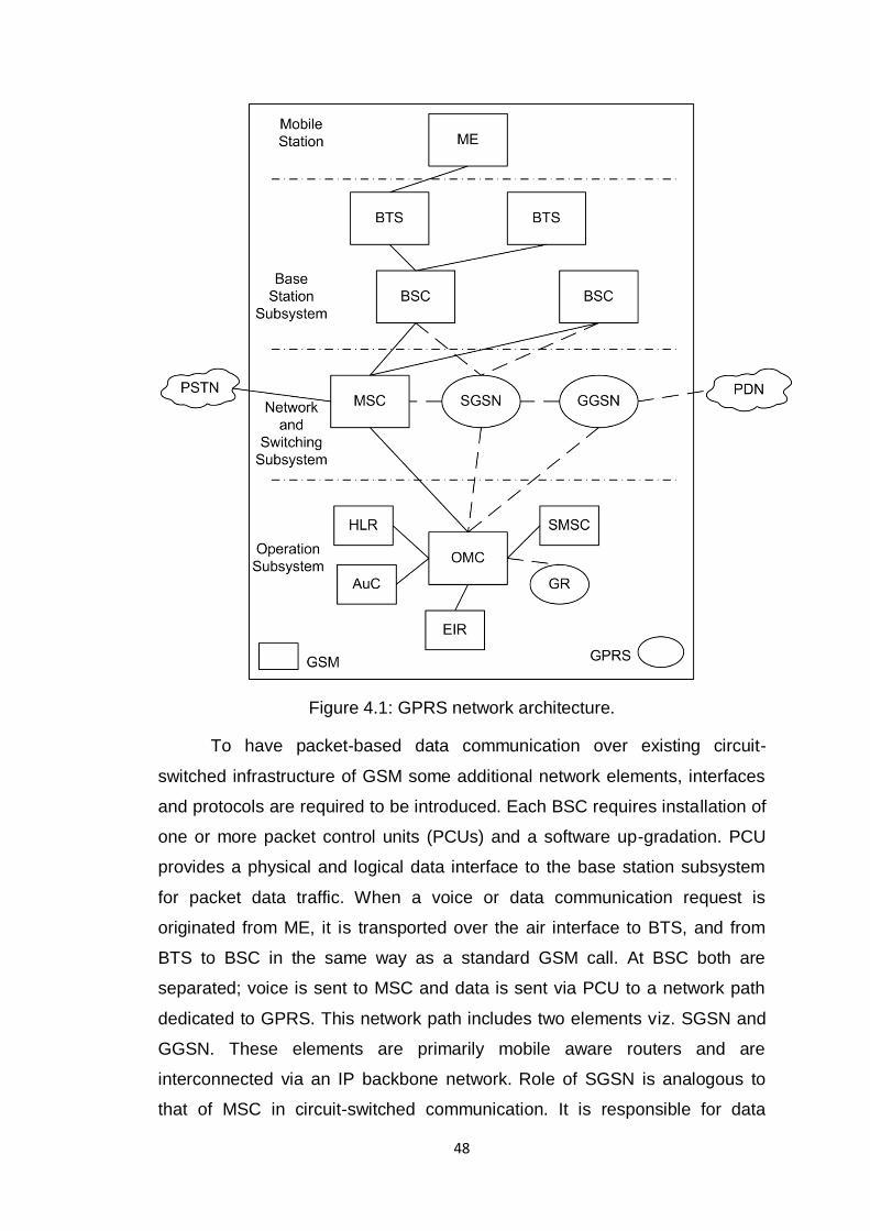
Architecture of a GPRS network as an overlay system to basic GSM
network is shown in Figure 4.1. Various network elements are defined in
Table 4.1.
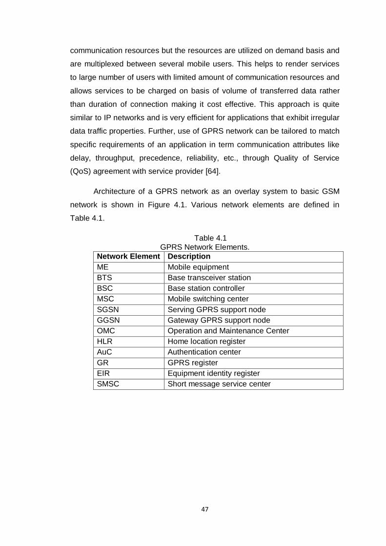
Table 4.1 GPRS Network Elements.
Network Element Description
ME Mobile equipment
BTS Base transceiver station
BSC Base station controller
MSC Mobile switching center
SGSN Serving GPRS support node
GGSN Gateway GPRS support node
OMC Operation and Maintenance Center
HLR Home location register
AuC Authentication center
GR GPRS register
EIR Equipment identity register
SMSC Short message service center
48
Figure 4.1: GPRS network architecture.
To have packet-based data communication over existing circuit-
switched infrastructure of GSM some additional network elements, interfaces
and protocols are required to be introduced. Each BSC requires installation of
one or more packet control units (PCUs) and a software up-gradation. PCU
provides a physical and logical data interface to the base station subsystem
for packet data traffic. When a voice or data communication request is
originated from ME, it is transported over the air interface to BTS, and from
BTS to BSC in the same way as a standard GSM call. At BSC both are
separated; voice is sent to MSC and data is sent via PCU to a network path
dedicated to GPRS. This network path includes two elements viz. SGSN and
GGSN. These elements are primarily mobile aware routers and are
interconnected via an IP backbone network. Role of SGSN is analogous to
that of MSC in circuit-switched communication. It is responsible for data
49
packet exchange with base station subsystem and for other functions like
authentication of GPRS mobiles, registration of mobiles in network, mobility
management, recording billing information, etc. GGSN acts as an interface
and a router to external PDN. GGSN contains routing information for GPRS
users that helps to pass packets through IP based internal backbone to
correct SGSN. GGSN also records billing information for use of external data
networks and also acts as a packet filter for incoming data. GR as a part of
operation subsystem is used to manage information related to each GPRS
subscriber as well as routing information.
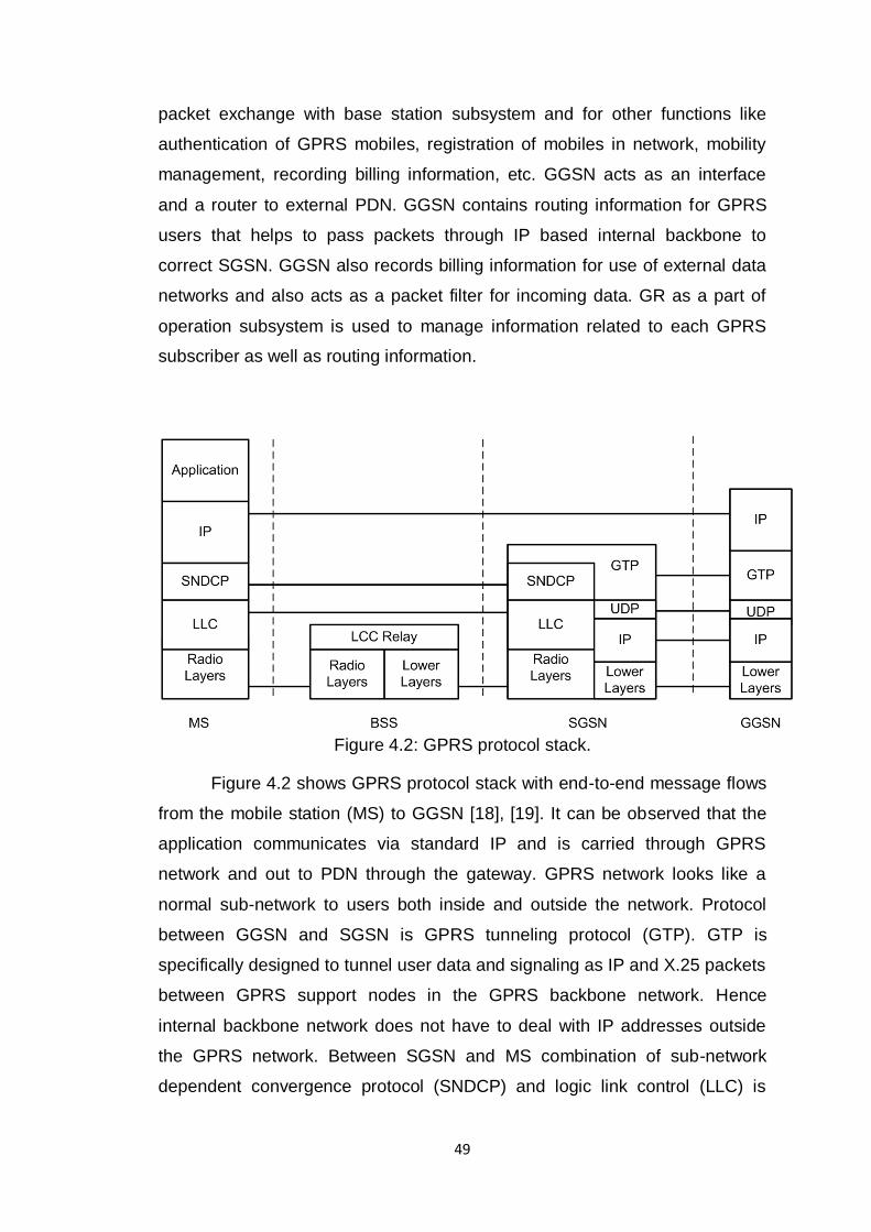
Figure 4.2: GPRS protocol stack.
Figure 4.2 shows GPRS protocol stack with end-to-end message flows
from the mobile station (MS) to GGSN [18], [19]. It can be observed that the
application communicates via standard IP and is carried through GPRS
network and out to PDN through the gateway. GPRS network looks like a
normal sub-network to users both inside and outside the network. Protocol
between GGSN and SGSN is GPRS tunneling protocol (GTP). GTP is
specifically designed to tunnel user data and signaling as IP and X.25 packets
between GPRS support nodes in the GPRS backbone network. Hence
internal backbone network does not have to deal with IP addresses outside
the GPRS network. Between SGSN and MS combination of sub-network
dependent convergence protocol (SNDCP) and logic link control (LLC) is
50
used. SNDCP compresses data to minimize the load on the radio channel and
LCC provides a safe logical link by encrypting packets.
4.2 Considerations for using GPRS technology for remote access
As discussed in Chapter 3, GSM-SMS technology provides very simple and
low-cost solution for remote data access. However, this approach is less
efficient and inconvenient when application requires large data transfer or
continuous data communication between remote devices. These limitations
can be overcome using GPRS technology for remote data access. GPRS are
designed to provide better network architecture for data communication.
GPRS based data networks offer an always-on connection and provide billing
based on the volume of data sent rather than the time of connection. Further,
data rates supported by GPRS (56–114 kbit/sec.) are quite sufficient for most
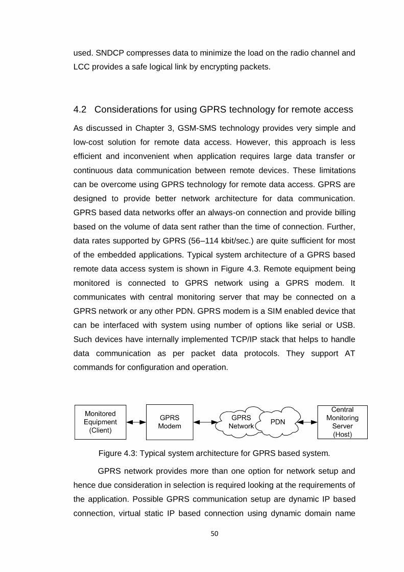
of the embedded applications. Typical system architecture of a GPRS based
remote data access system is shown in Figure 4.3. Remote equipment being
monitored is connected to GPRS network using a GPRS modem. It
communicates with central monitoring server that may be connected on a
GPRS network or any other PDN. GPRS modem is a SIM enabled device that
can be interfaced with system using number of options like serial or USB.
Such devices have internally implemented TCP/IP stack that helps to handle
data communication as per packet data protocols. They support AT
commands for configuration and operation.
Figure 4.3: Typical system architecture for GPRS based system.
GPRS network provides more than one option for network setup and
hence due consideration in selection is required looking at the requirements of
the application. Possible GPRS communication setup are dynamic IP based
connection, virtual static IP based connection using dynamic domain name
51
server (DDNS), VPN based connection [65] and push architecture based
connection [66]. Characteristics of each of these options are discussed as
follows.
Dynamic IP based connection
If the application requires that the client (device to be monitored connected to
the modem) reports the host (central monitoring server) periodically about
status updates or report by exception generated if any, the dynamic IP service
can be used. Dynamic IP based connection is the default communication
setup provided by GPRS service provider when a GPRS connection is
requested by the mobile station. It is called dynamic IP because the IP
address assigned for communication is not fixed and may change every time
GPRS connection is requested. In this communication setup whenever the
client intends to transfer data to the host either periodically or because of
occurrence of any exception, it becomes online and communicates the data to
the host. The host in this case is required to have a static IP. With dynamic IP
based communication, host may only receive the data from the client or at the
most respond to client request once the information of current dynamic IP has
been sent to it. Host will not be able to initiate the communication with the
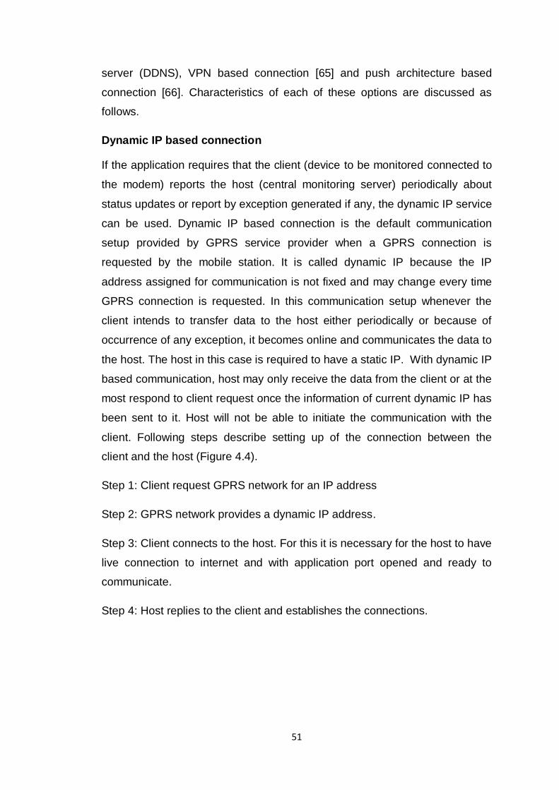
client. Following steps describe setting up of the connection between the
client and the host (Figure 4.4).
Step 1: Client request GPRS network for an IP address
Step 2: GPRS network provides a dynamic IP address.
Step 3: Client connects to the host. For this it is necessary for the host to have
live connection to internet and with application port opened and ready to
communicate.
Step 4: Host replies to the client and establishes the connections.
52
Figure 4.4: Communication setup based on dynamic IP.
The connection once established remains active till the time data flow
exist. If the connection is found to be idle for an extended period the
connection is dropped off and has to be reinitialized whenever required again.
Virtual static IP based connection using Dynamic domain name server
Applications that require the host to contact the remote client for collecting the
data or sending the command, simple dynamic IP based setup cannot be
useful. One possible approach is to assign each client a static IP. This makes
communication setup very straight forward but is not always a feasible
solution for more than one reason. Many, but not all, GPRS service providers
allot a static IP to a specific SIM card. Further having a static IP for each
individual client is costly. This will also make the client relatively exposed on
internet and hence this approach requires measures to protect unauthorized
access. In such a scenario solution of introducing DDNS in communication
setup provides one of the alternative solutions. DDNS is one type of domain
name server (DNS) that is responsible for mapping each client name with its
current dynamic IP assigned by GPRS network [67]. In this case each client is
assigned a fixed client name and the host will be able to access the client
using that client name with the help of DDNS. Thus from the end of the host
each client has a fixed IP. Client will be responsible to update its current
dynamic IP to DDNS and DDNS in turn maps it to its client name. Following
53
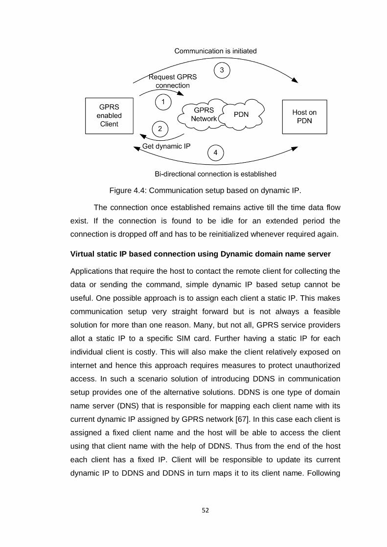
steps describe setting up of the connection between the client and the host
(Figure 4.5).
Figure 4.5: Communication setup based on DDNS.
Step 1: Client request GPRS network for an IP address
Step 2: GPRS network provides a dynamic IP address.
Step 3: Client connects to the DDNS and register its dynamic IP and maintain
a live connection.
Step 4: Host contacts DDNS to know the IP of client to be contacted using
fixed client name.
Step 5: Host resolves the dynamic IP address of client from DDNS.
Step 6: Host contacts the client on its dynamic IP and bi-directional
communication is established.
This approach has couple of concerns to be considered. First is that
DDNS service is usually provided by a third party service provider and hence
quality of service depends on them. Further, this would involve service
charges to be paid to DDNS service provider. Also, if DDNS do not support
standard protocol for IP address updates it becomes difficult for client to
54
communicate. In addition to this, client must be smart enough to maintain
GPRS connection live when host is not in communication.
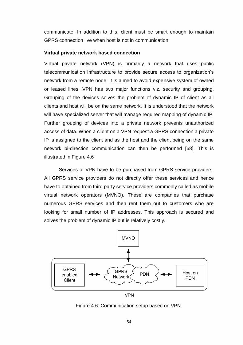
Virtual private network based connection
Virtual private network (VPN) is primarily a network that uses public
telecommunication infrastructure to provide secure access to organization’s
network from a remote node. It is aimed to avoid expensive system of owned
or leased lines. VPN has two major functions viz. security and grouping.
Grouping of the devices solves the problem of dynamic IP of client as all
clients and host will be on the same network. It is understood that the network
will have specialized server that will manage required mapping of dynamic IP.
Further grouping of devices into a private network prevents unauthorized
access of data. When a client on a VPN request a GPRS connection a private
IP is assigned to the client and as the host and the client being on the same
network bi-direction communication can then be performed [68]. This is
illustrated in Figure 4.6
Services of VPN have to be purchased from GPRS service providers.
All GPRS service providers do not directly offer these services and hence
have to obtained from third party service providers commonly called as mobile
virtual network operators (MVNO). These are companies that purchase
numerous GPRS services and then rent them out to customers who are
looking for small number of IP addresses. This approach is secured and
solves the problem of dynamic IP but is relatively costly.
Figure 4.6: Communication setup based on VPN.
55
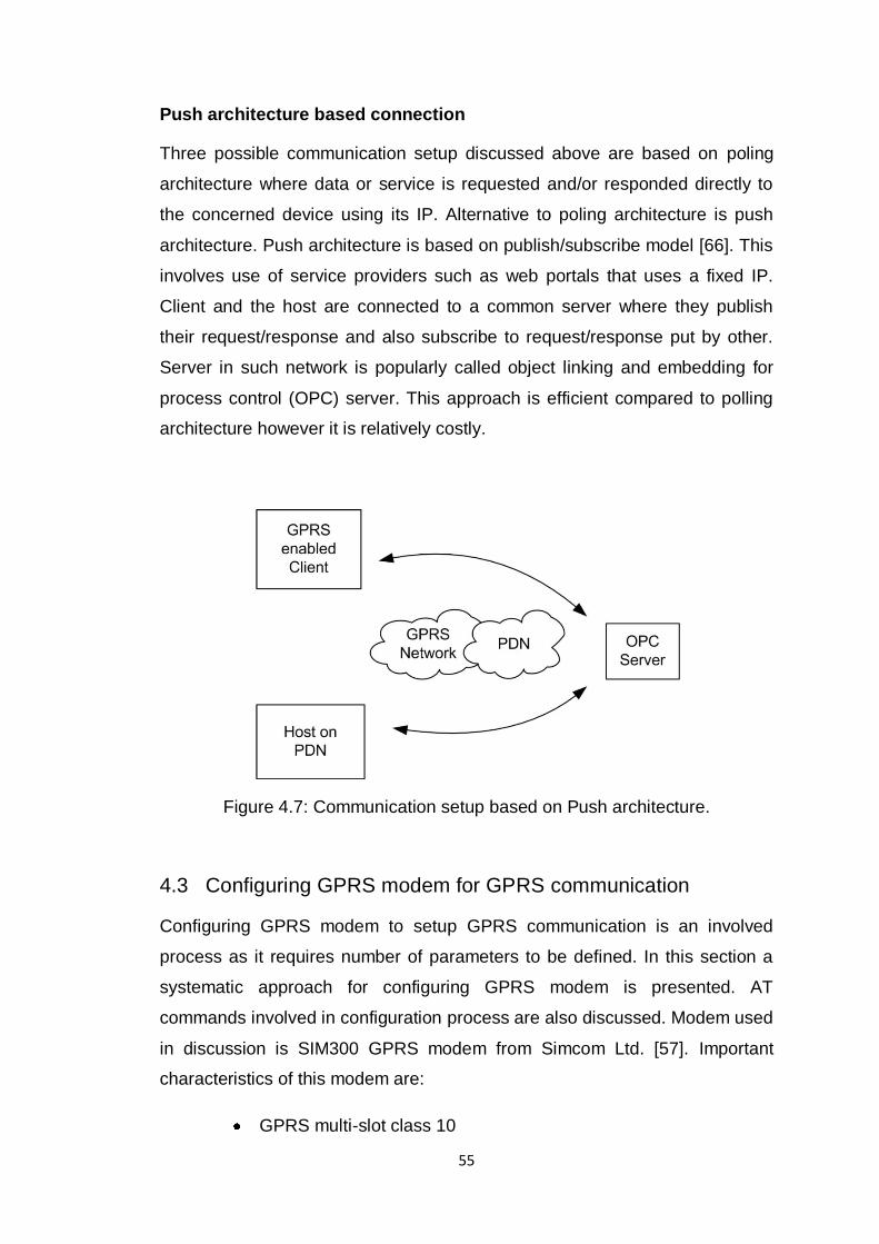
Push architecture based connection
Three possible communication setup discussed above are based on poling
architecture where data or service is requested and/or responded directly to
the concerned device using its IP. Alternative to poling architecture is push
architecture. Push architecture is based on publish/subscribe model [66]. This
involves use of service providers such as web portals that uses a fixed IP.
Client and the host are connected to a common server where they publish
their request/response and also subscribe to request/response put by other.
Server in such network is popularly called object linking and embedding for
process control (OPC) server. This approach is efficient compared to polling
architecture however it is relatively costly.
Figure 4.7: Communication setup based on Push architecture.
4.3 Configuring GPRS modem for GPRS communication
Configuring GPRS modem to setup GPRS communication is an involved
process as it requires number of parameters to be defined. In this section a
systematic approach for configuring GPRS modem is presented. AT
commands involved in configuration process are also discussed. Modem used
in discussion is SIM300 GPRS modem from Simcom Ltd. [57]. Important
characteristics of this modem are:
GPRS multi-slot class 10
56
GPRS mobile station class B
In-built TCP/IP protocol with PPP-stack
Data downlink transfer: max. 85.6 kbps
Data uplink transfer: max. 42.8 kbps.
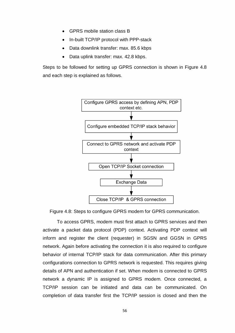
Steps to be followed for setting up GPRS connection is shown in Figure 4.8
and each step is explained as follows.
Figure 4.8: Steps to configure GPRS modem for GPRS communication.
To access GPRS, modem must first attach to GPRS services and then
activate a packet data protocol (PDP) context. Activating PDP context will
inform and register the client (requester) in SGSN and GGSN in GPRS
network. Again before activating the connection it is also required to configure
behavior of internal TCP/IP stack for data communication. After this primary
configurations connection to GPRS network is requested. This requires giving
details of APN and authentication if set. When modem is connected to GPRS
network a dynamic IP is assigned to GPRS modem. Once connected, a
TCP/IP session can be initiated and data can be communicated. On
completion of data transfer first the TCP/IP session is closed and then the
57
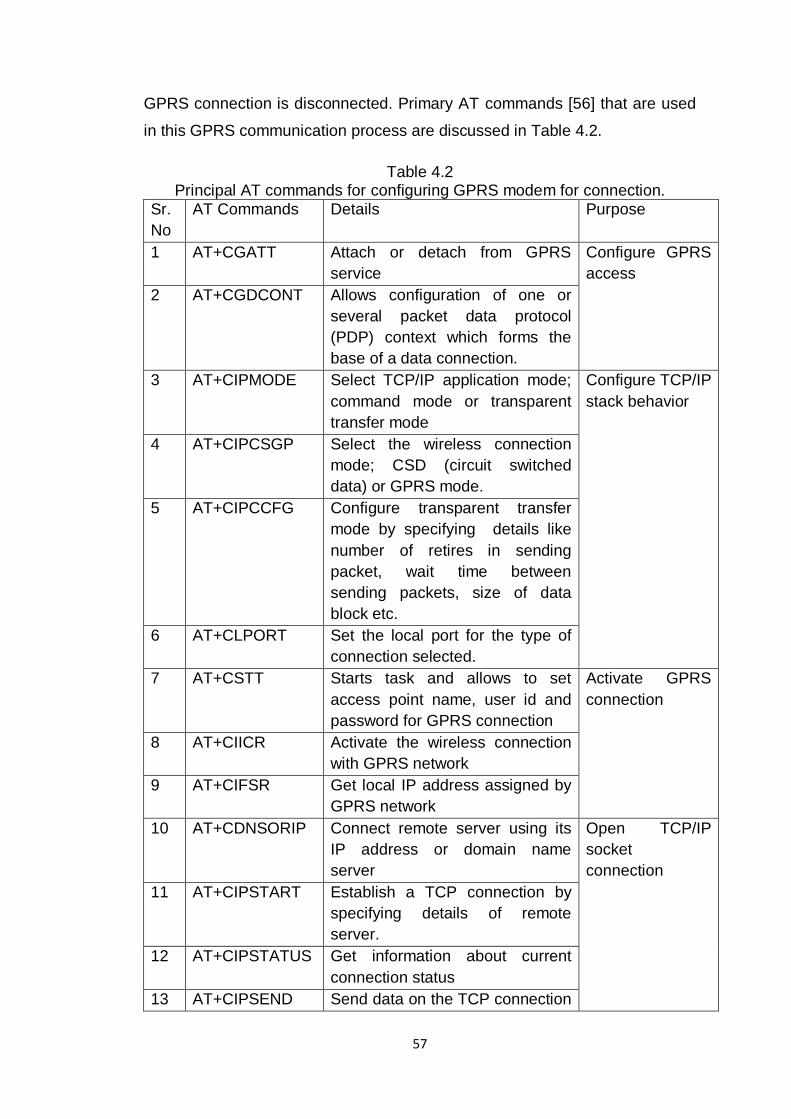
GPRS connection is disconnected. Primary AT commands [56] that are used
in this GPRS communication process are discussed in Table 4.2.
Table 4.2 Principal AT commands for configuring GPRS modem for connection.
Sr.
No
AT Commands Details Purpose
1 AT+CGATT Attach or detach from GPRS
service
Configure GPRS
access
2 AT+CGDCONT Allows configuration of one or
several packet data protocol
(PDP) context which forms the
base of a data connection.
3 AT+CIPMODE Select TCP/IP application mode;
command mode or transparent
transfer mode
Configure TCP/IP
stack behavior
4 AT+CIPCSGP Select the wireless connection
mode; CSD (circuit switched
data) or GPRS mode.
5 AT+CIPCCFG Configure transparent transfer
mode by specifying details like
number of retires in sending
packet, wait time between
sending packets, size of data
block etc.
6 AT+CLPORT Set the local port for the type of
connection selected.
7 AT+CSTT Starts task and allows to set
access point name, user id and
password for GPRS connection
Activate GPRS
connection
8 AT+CIICR Activate the wireless connection
with GPRS network
9 AT+CIFSR Get local IP address assigned by
GPRS network
10 AT+CDNSORIP Connect remote server using its
IP address or domain name
server
Open TCP/IP
socket
connection
11 AT+CIPSTART Establish a TCP connection by
specifying details of remote
server.
12 AT+CIPSTATUS Get information about current
connection status
13 AT+CIPSEND Send data on the TCP connection
58
that has been established
already.
14 AT+CIPCLOSE Close TCP connection if active. Close TCP/IP
and GPRS
connection
15 AT+CIPSHUT Disconnect the wireless
connection
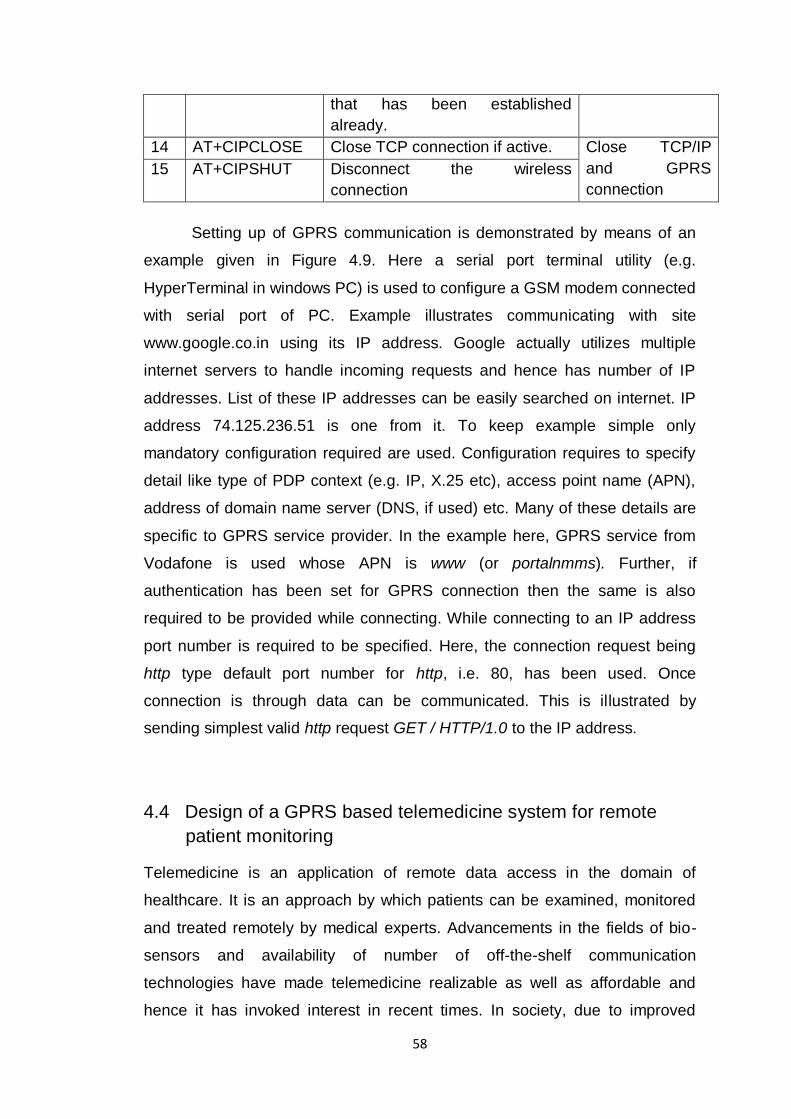
Setting up of GPRS communication is demonstrated by means of an
example given in Figure 4.9. Here a serial port terminal utility (e.g.
HyperTerminal in windows PC) is used to configure a GSM modem connected
with serial port of PC. Example illustrates communicating with site
www.google.co.in using its IP address. Google actually utilizes multiple
internet servers to handle incoming requests and hence has number of IP
addresses. List of these IP addresses can be easily searched on internet. IP
address 74.125.236.51 is one from it. To keep example simple only
mandatory configuration required are used. Configuration requires to specify
detail like type of PDP context (e.g. IP, X.25 etc), access point name (APN),
address of domain name server (DNS, if used) etc. Many of these details are
specific to GPRS service provider. In the example here, GPRS service from
Vodafone is used whose APN is www (or portalnmms). Further, if
authentication has been set for GPRS connection then the same is also
required to be provided while connecting. While connecting to an IP address
port number is required to be specified. Here, the connection request being
http type default port number for http, i.e. 80, has been used. Once
connection is through data can be communicated. This is illustrated by
sending simplest valid http request GET / HTTP/1.0 to the IP address.
4.4 Design of a GPRS based telemedicine system for remote
patient monitoring
Telemedicine is an application of remote data access in the domain of
healthcare. It is an approach by which patients can be examined, monitored
and treated remotely by medical experts. Advancements in the fields of bio-
sensors and availability of number of off-the-shelf communication
technologies have made telemedicine realizable as well as affordable and
hence it has invoked interest in recent times. In society, due to improved
59
medical facilities, average life span of a person has increased and hence the
elderly population, who requires regular medical care. Further, enhancements
in standards of livings have made people to pay more attention towards
regular health examination. In this situation option of telemedicine can prove
not only to be convenient but also cost effective and efficient [69].
Advancement in telemedicine can be particularly beneficial in developing
countries like India where majority of population live in rural areas where
services of medical experts are relatively less.
Figure 4.9: Example of setting up a GPRS connection.
60
Data to be communicated in any telemedicine system generally is
either relatively large or continuous that makes GPRS technology an ideal
solution for communication. As a part of present work design of a GPRS
based telemedicine system is proposed and a prototype is implemented to
support the design concept. The system designed communicates an ECG
signal generated from a MATLAB based ECG simulator to a remote
monitoring center connected to internet using GPRS network. Design concept
and implementation of the system is discussed in following part of this section.
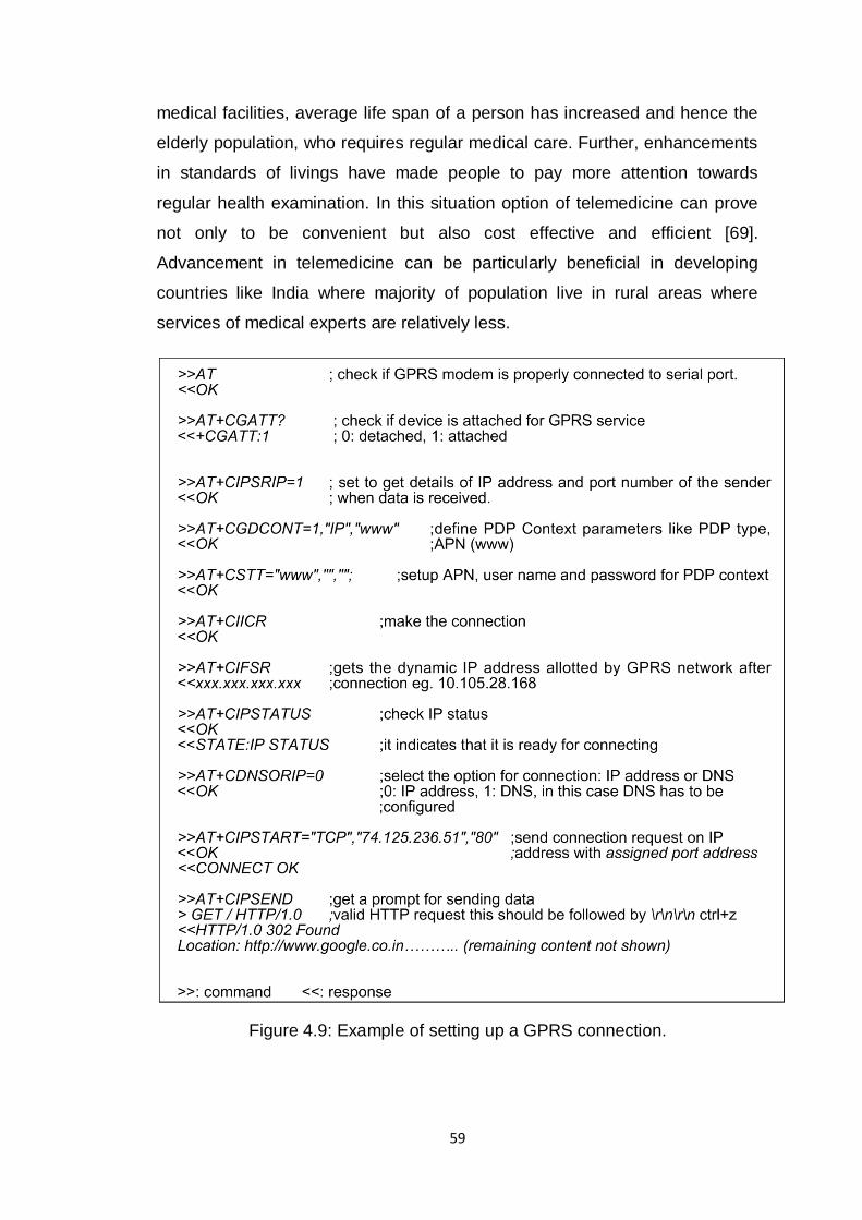
4.4.1 System architecture
Typical telemedicine system based on GPRS is composed of the physiology
data acquisition module, intelligent control terminal, GPRS network and a
remote monitoring server. This is illustrated in Figure 4.10.
Figure 4.10: System architecture of a GPRS based telemedicine system.
Design of a physiology data acquisition module depends on the nature
of biomedical signal to be acquired, however in general it involves medical
sensors, and signal conditioning unit primarily consisting of filters, amplifiers
and analog to digital converters. In current times such data acquisition
modules related to measurements of ECG, blood pressure, heart rate,
respiratory pressure, etc. are available in large variety in the market. These
modules are accurate, handy, low cost and easy to use even without expert
medical assistance. Many of them are also with the facility of data
communication through either RS-232 or USB interface.
Intelligent control terminal is generally a microcontroller based unit with
GPRS modem. The terminal works to read the data from the physiology data
acquisition unit and communicates it to remote monitoring server over GPRS
network. Intelligent control terminal may also be supported with some function
keys and local display for procedural assistance to user.
61
Remote monitoring server represents a monitoring station and
information management system that is connected to internet. Main function
of this module is to receive data from remote terminal and store it in database
managed by information management system. It generally provides multi-user
support and real-time monitoring. Information management system may
include data analysis system, patient records, authentication features and
system database.
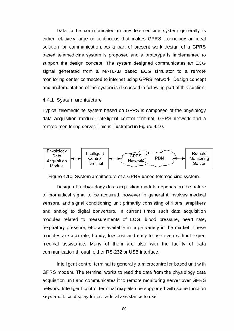
4.4.2 System implementation
As the present work is more related to study of technologies for remote data
access, in implementation of a telemedicine system, the primary focus has
been on design of intelligent control terminal. Block diagram of the system
implemented is shown in Figure 4.11.
Figure 4.11: Design of intelligent control terminal.
In system implementation physiological data acquisition module is
simulated using a MATLAB based application that runs on a PC and acts as a
source of data. The application consist of two modules; one for generating an
ECG signal making use of a MATLAB based ECG simulator [70] and second
for communicating with intelligent control terminal over the serial port. ECG
simulator used is able to generate lead II ECG waveform. ECG waveform
obtained from lead II is most important from the point of view of diagnosis and
it consists of P, Q, R, S and T waves. Simulator used provides facility to
62
generate normal ECG waveform as well as waveform with induced
abnormalities. Simulator provides following features.
1. Set desired heart beat rate.
2. Set intervals between P, Q, R, S and T waves.
3. Set amplitude of P, Q, R, S and T waves.
4. Simulate fibrillation condition.
5. Simulate addition of noise due to motion artifacts or other reasons.
6. Set duration for recording ECG
Intelligent control terminal has been designed using ARM7 based 32-
bit microcontroller LPC2148 from NXP Philips. Specifications of LPC2148 [71]
are discussed in detail in Appendix D. It is primarily an ideal selection for
applications like this because of its computationally efficient 32-bit ARM7
based CPU, high speed and low power consumption. It has on-chip 512kB of
Flash memory and 32kB of RAM. It supports for varieties of communication
interfaces like USB2.0, multiple UARTs, multiple I2C (inter integrated circuit),
SPI (serial peripheral interface), SSP (synchronous serial port), etc. It has up
to 45 general purpose I/O lines and other useful on-chip peripherals like
multiple ADCs, multiple timers, DAC, PWM, multiple interrupts, etc. Primary
elements interfaced with controller are: PC with MATLAB application acting as
source of data, SIM enabled GPRS modem for communicating with remote
server and a LCD unit for local display. Circuit design of intelligent control
terminal is given in Appendix E [72]. Intelligent control terminal performs
following operations.
1. Configure GPRS modem to setup communication link.
2. Instruct ECG simulator to generate and communicate ECG signal.
3. Communicate data received from simulator to remote monitoring
station.
4. Continuously display the current state of process on LCD display.
Remote monitoring station is again a server connected to internet.
Server runs an application program designed in MATLAB. As discussed later
in this section, application program is primarily a TCP/IP server socket
designed using Java Objects imported in MATLAB environment. On receiving
63
the request for data communication from the remote client, in our case the
intelligent control terminal, the application program establishes the
connection, receives data and stores it in database for later use.
4.4.3 System software
Software for the implemented system consist of three main modules namely
software for generating ECG signals acting as source of data, software for
managing functionality of intelligent control terminal and software for receiving
the data at remote monitoring terminal. Software for data generation and for
monitoring station are developed in MATLAB whereas program for intelligent
control terminal has been developed in Embedded C using Keil uVision 4 IDE
for ARM based microcontrollers. These modules are discussed as follows.
Software module for generating ECG
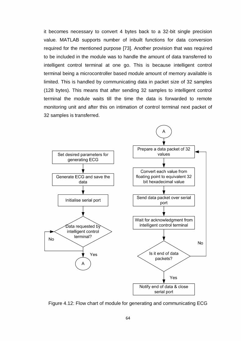
This module is responsible for two main functions viz. generating ECG and
passing it to intelligent control terminal as directed. Flow chart explaining the
sequence of execution in this module of system software is shown in Figure
4.12. MATLAB code for ECG simulator permits to set parameters related to
ECG signal like duration of signal, heart rate, and characteristics of each P, Q,
R, S and T wave in terms of its amplitude, duration and interval between
waves. Once these parameters are defined ECG signal gets generated and
saved. The simulator generates ECG signal at a rate of 100 samples/sec with
each sample represented as a double precision 64-bit floating point value. On
receiving the request for ECG data from the intelligent control terminal the
module starts data communication. However, as standard UART supports
data format with data of 8 bits, the data generated by the simulator is required
to be appropriately formatted. Two operations are performed for the said
purpose. First operation is of quantizing 64-bit representation obtained from
simulator to 32-bit single precision representation so as to reduce the size of
data to be communicated. And second operation is converting this 32-bit
value into equivalent 32 bit hexadecimal value. This helps to represent each
sample of ECG into 4 byte of data that can be conveniently communicated. It
has been verified that no significant error is introduced due to quantization
and the signal is satisfactorily recovered back. However, on the receiver side
64
it becomes necessary to convert 4 bytes back to a 32-bit single precision
value. MATLAB supports number of inbuilt functions for data conversion
required for the mentioned purpose [73]. Another provision that was required
to be included in the module was to handle the amount of data transferred to
intelligent control terminal at one go. This is because intelligent control
terminal being a microcontroller based module amount of memory available is
limited. This is handled by communicating data in packet size of 32 samples
(128 bytes). This means that after sending 32 samples to intelligent control
terminal the module waits till the time the data is forwarded to remote
monitoring unit and after this on intimation of control terminal next packet of
32 samples is transferred.
Figure 4.12: Flow chart of module for generating and communicating ECG
65
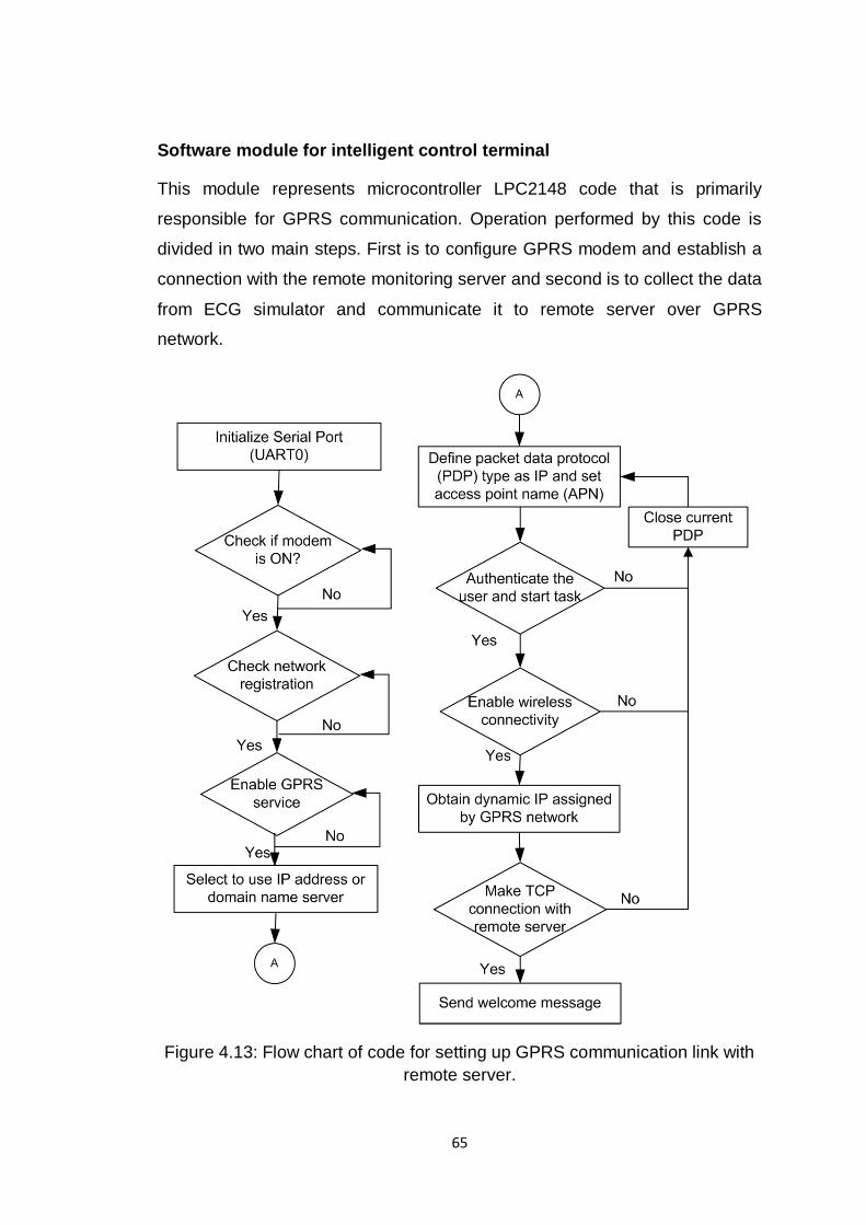
Software module for intelligent control terminal
This module represents microcontroller LPC2148 code that is primarily
responsible for GPRS communication. Operation performed by this code is
divided in two main steps. First is to configure GPRS modem and establish a
connection with the remote monitoring server and second is to collect the data
from ECG simulator and communicate it to remote server over GPRS
network.
Figure 4.13: Flow chart of code for setting up GPRS communication link with
remote server.
66
Detailed discussion on configuring GPRS modem for data
communication has been presented in Section 4.2. Following same steps,
execution flow for establishing connection with remote server has been
developed as shown in Figure 4.13. Code has been developed in Embedded
C. The code is written such that for each AT command sent to the modem the
response received is checked to identify its successful execution. If the
command gets executed successfully code moves to the next step and in
case of error the step (or all required previous steps) is (are) repeated for
fixed number of times before suspending the process. For example as shown
in the flow chart, during initialization once a PDP context is defined if any of
the AT commands fails to execute successfully then the current IP session
has to be closed and once again a fresh PDP context has to be defined.
Stepwise progress in code execution is updated on LCD with an aim to help
user to identify the current state of execution and also to pin-point the error, if
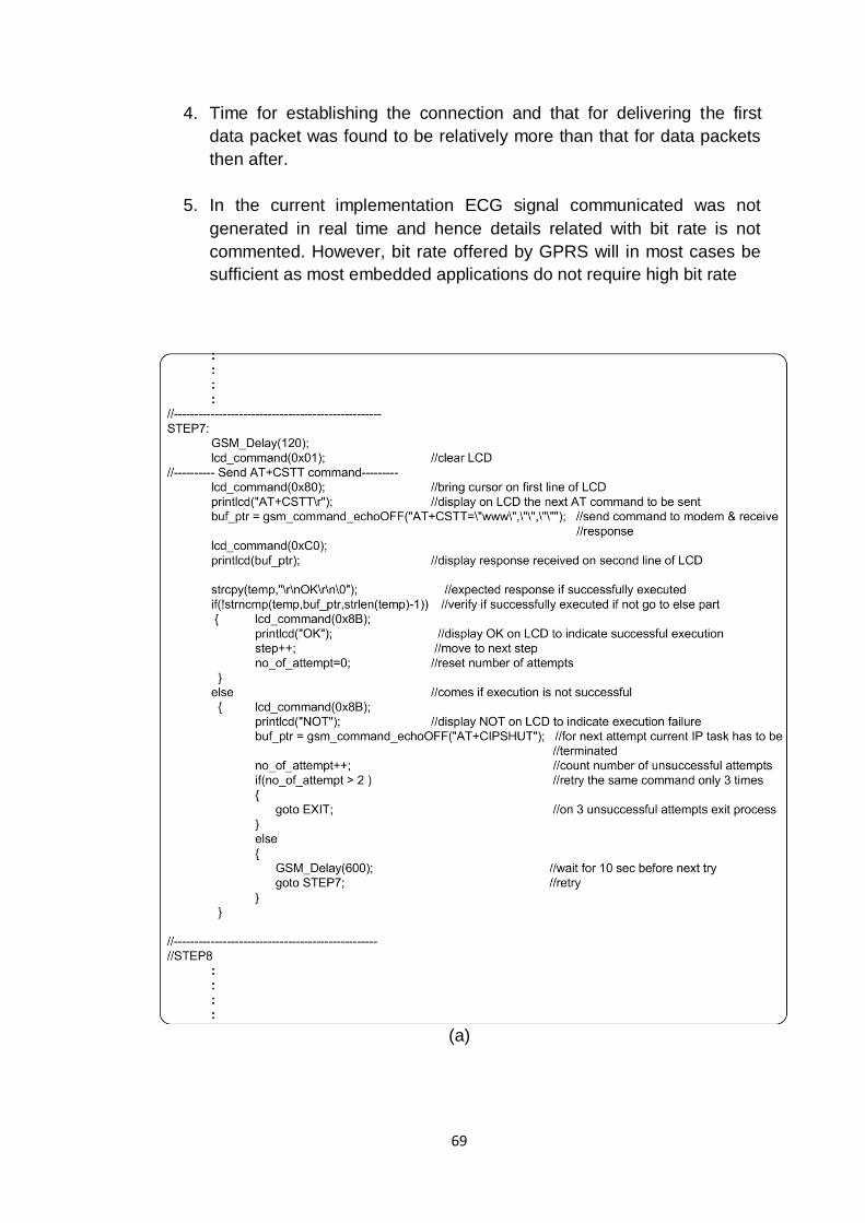
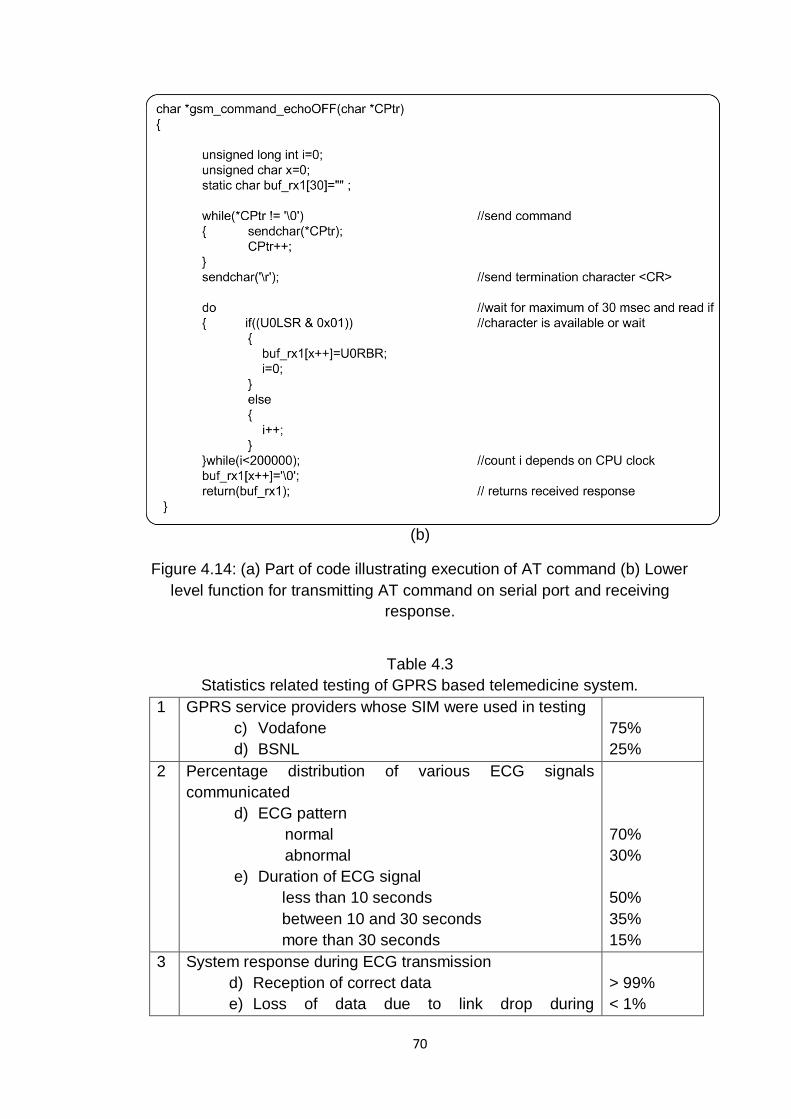
any, during execution. Small part of the code is shown in Figure 4.14 for
illustration. Code in Figure 4.14(a) explains activities performed when an AT
command (in this case AT+CSTT) is issued to GPRS modem. These activities
are listed as follows.
1. Display the command to be executed on LCD.
2. Issue the command using function gsm_command_echoOFF as given
in Figure 4.14(b) and receive the response
3. Display the received response on LCD.
4. Compare the received response with the expected response if
successfully executed.
5. If execution is successful display OK message on LCD, proceed to
next step and if this command had required more than one attempts to
execute then reset this attempts to zero.
6. If execution is not successful display NOT message on LCD, close the
current IP session, if required, and increment the count of failed
attempt. If the count of failed attempt exceeds more then decided (here
3) then leave the initialization process otherwise move to the previous
step as required.
67
Figure 4.14(b) explain a lower level function gsm_command_echoOFF that
sends AT command to GSM modem over the serial port and receives the
response in return. Here the command is sent character by character and
same way the response is received and stored. After, issuing the command
code wait for specified time duration (here 30 msec) for modem to respond. If
the response is not received during the stipulated time the function returns
null response indicating failure in execution.
Software module for remote monitoring server
Software module at remote monitoring server is a TCP/IP server socket
designed in MATLAB. The code is meant to be executed on a PC connected
to internet and performs two functions. It receives the data as sent by the
intelligent control terminal and stores it for later use. For receiving the data
over TCP/IP, a TCP/IP object (socket) has to be created in MATLAB.
MATLAB supports tcpip( ) function that helps to create a TCP/IP object that
can be used for TCP/IP based communication with remote port [74]. However,
while creating such object it requires IP address of remote terminal. This
information always remains unavailable at server side before the connection
is established as the type of GPRS connection used by intelligent control
terminal is based on dynamic IP address. Hence for creating a TCP/IP socket
java objects are imported in MATLAB environment [75]. For example class
ServerSocket is used for creating a TCP/IP socket in java [76]. This does not
require IP address of remote terminal but only the port address of the
application. Socket waits for request for connection to come in over the
network from the specified port address and once received establishes the
connection. Both client and server should agree on the same port address.
Port address can be basically any 16-bit unsigned integer. However, many
port addresses have been accepted as a standard or are registered. Port
address range 49152-65536 is considered as dynamic or private and cannot
be registered and hence it is open for use [77]. Basic steps performed by this
software module are as follows.
1. Create a server socket with designated port address using
ServerSocket().
68
2. Wait for the remote client to connect.
3. Receive the data packets till special data packet indicating end of data
is not received.
4. Convert the data received into appropriate 32 bit single precision
representation and store it.
5. Move to step 2.
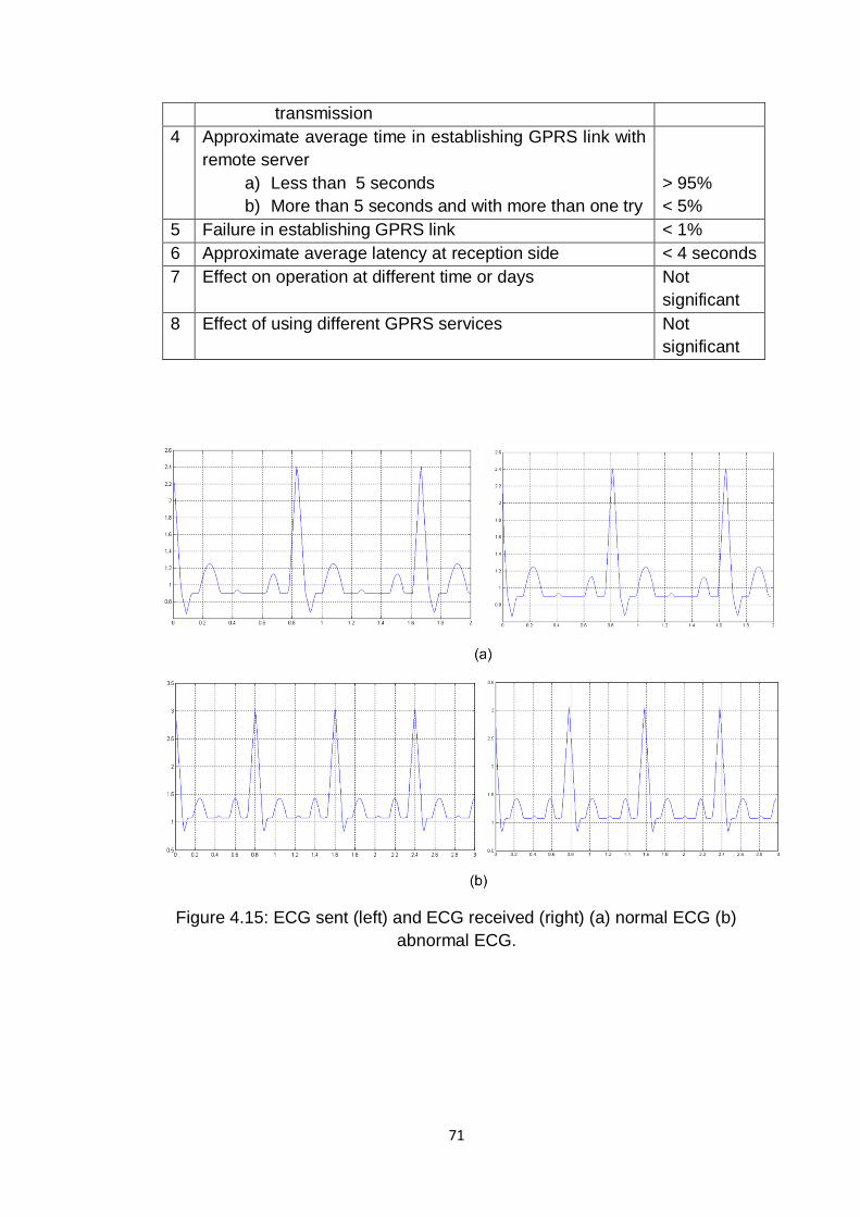
4.4.4 Experimental results and discussion
In this section various operations performed to verify operation of GPRS
based telemedicine system are discussed. Before integrating complete
system each unit viz. ECG generation unit, microcontroller based control
terminal and remote monitoring server very individually tested. Tools like
Windows HyperTerminal, Hercules setup utility [78] were used in verifying
operations and correcting bugs. Operation of complete system was verified for
number of test conditions. For example, ECG signals with different patterns
were generated for varying durations and were communicated. Further, with
an aim to test GPRS communication under different traffic conditions on the
network system was tested at different times and on different days of the
week. In Figure 4.15 two ECG patters representing different cardiac
conditions as sent and received are shown. Statistics related to system
response during communication of ECG signal are discussed in Table 4.3.
Important observations made during the experimental stage are
discussed as follows.
1. Communication was established quickly and it was reliable.
2. Pattern of data communication as observed was not regular but bursty.
It was observed that all data packets do not reach the destination in
almost equal time. Further, more than one data packets may be
delivered together after a delay more than delay in delivering single
data packet. However, the average time was always found to be within
expectable limits.
3. Network traffic conditions do affect the operation but it was relatively
difficult to anticipate the effect.
69
4. Time for establishing the connection and that for delivering the first
data packet was found to be relatively more than that for data packets
then after.
5. In the current implementation ECG signal communicated was not
generated in real time and hence details related with bit rate is not
commented. However, bit rate offered by GPRS will in most cases be
sufficient as most embedded applications do not require high bit rate
(a)
70
(b)
Figure 4.14: (a) Part of code illustrating execution of AT command (b) Lower
level function for transmitting AT command on serial port and receiving
response.
Table 4.3
Statistics related testing of GPRS based telemedicine system.
1 GPRS service providers whose SIM were used in testing
c) Vodafone
d) BSNL
75%
25%
2 Percentage distribution of various ECG signals
communicated
d) ECG pattern
normal
abnormal
e) Duration of ECG signal
less than 10 seconds
between 10 and 30 seconds
more than 30 seconds
70%
30%
50%
35%
15%
3 System response during ECG transmission
d) Reception of correct data
e) Loss of data due to link drop during
> 99%
< 1%
71
transmission
4 Approximate average time in establishing GPRS link with
remote server
a) Less than 5 seconds
b) More than 5 seconds and with more than one try
> 95%
< 5%
5 Failure in establishing GPRS link < 1%
6 Approximate average latency at reception side < 4 seconds
7 Effect on operation at different time or days Not
significant
8 Effect of using different GPRS services Not
significant
Figure 4.15: ECG sent (left) and ECG received (right) (a) normal ECG (b)
abnormal ECG.