Embed Size (px)
Citation preview

4.A-1 Air conditioning systems in large building are required to bring in 20 cubic feet per minute (cfm) of outdoor air per occupant, according to ASHRAE Standard 62. In a particular case, the Heating, Ventilating and Air Conditioning (HVAC) system for a building is being designed for a capacity of Np = 200 persons. As shown in Figure 4.A-1, outdoor air at T1 = 92°F is brought into the building through a D1 = 2.5 ft diameter circular duct and mixed with chilled air at T2 = 55°F that is flowing through a D2 = 4 ft diameter duct at velocity 2V = 600 ft/min. The pressure of all of the air streams is P = 1 atm.
Mixing box
D1 = 2.5 ft
D2 = 4 ft
discharge air1 atm
300 ft/minout
PV==
300 ft/minoutV =
300 ft/minoutV =
300 ft/minoutV =
1
1
outdoor air92 F, 1 atm20 cfm/person
T PV= ° ==
2
2
chilled air55 F, 1 atm600 ft/min
T PV
= ° ==
Figure 4.A-1: Mixing box.
The mixture is discharged at with velocity outV = 300 ft/min through 4 identical exit ducts to reduce duct noise. Assume that the mixing process is adiabatic and steady-state and neglect the humidity in the air. Do not neglect the kinetic energy of the streams. a.) What is the temperature of the discharge, mixed air? b.) Determine the necessary diameter of the four discharge ducts.
© S.A. Klein and G.F. Nellis Cambridge University Press, 2011
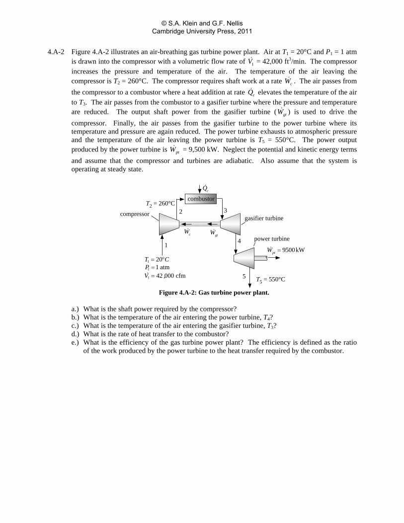
4.A-2 Figure 4.A-2 illustrates an air-breathing gas turbine power plant. Air at T1 = 20°C and P1 = 1 atm is drawn into the compressor with a volumetric flow rate of 1V = 42,000 ft3/min. The compressor increases the pressure and temperature of the air. The temperature of the air leaving the compressor is T2 = 260°C. The compressor requires shaft work at a rate cW . The air passes from the compressor to a combustor where a heat addition at rate cQ elevates the temperature of the air to T3. The air passes from the combustor to a gasifier turbine where the pressure and temperature are reduced. The output shaft power from the gasifier turbine ( gtW ) is used to drive the compressor. Finally, the air passes from the gasifier turbine to the power turbine where its temperature and pressure are again reduced. The power turbine exhausts to atmospheric pressure and the temperature of the air leaving the power turbine is T5 = 550°C. The power output produced by the power turbine is ptW = 9,500 kW. Neglect the potential and kinetic energy terms and assume that the compressor and turbines are adiabatic. Also assume that the system is operating at steady state.
compressorgasifier turbine
power turbine
1
1
1
201 atm42 000 cfm
T CPV ,
= °==
T2 = 260°C
cQ
combustor
1
2 3
gtW4
5 T5 = 550°C
9500kWptW =
cW
Figure 4.A-2: Gas turbine power plant.
a.) What is the shaft power required by the compressor? b.) What is the temperature of the air entering the power turbine, T4? c.) What is the temperature of the air entering the gasifier turbine, T3? d.) What is the rate of heat transfer to the combustor? e.) What is the efficiency of the gas turbine power plant? The efficiency is defined as the ratio
of the work produced by the power turbine to the heat transfer required by the combustor.
© S.A. Klein and G.F. Nellis Cambridge University Press, 2011
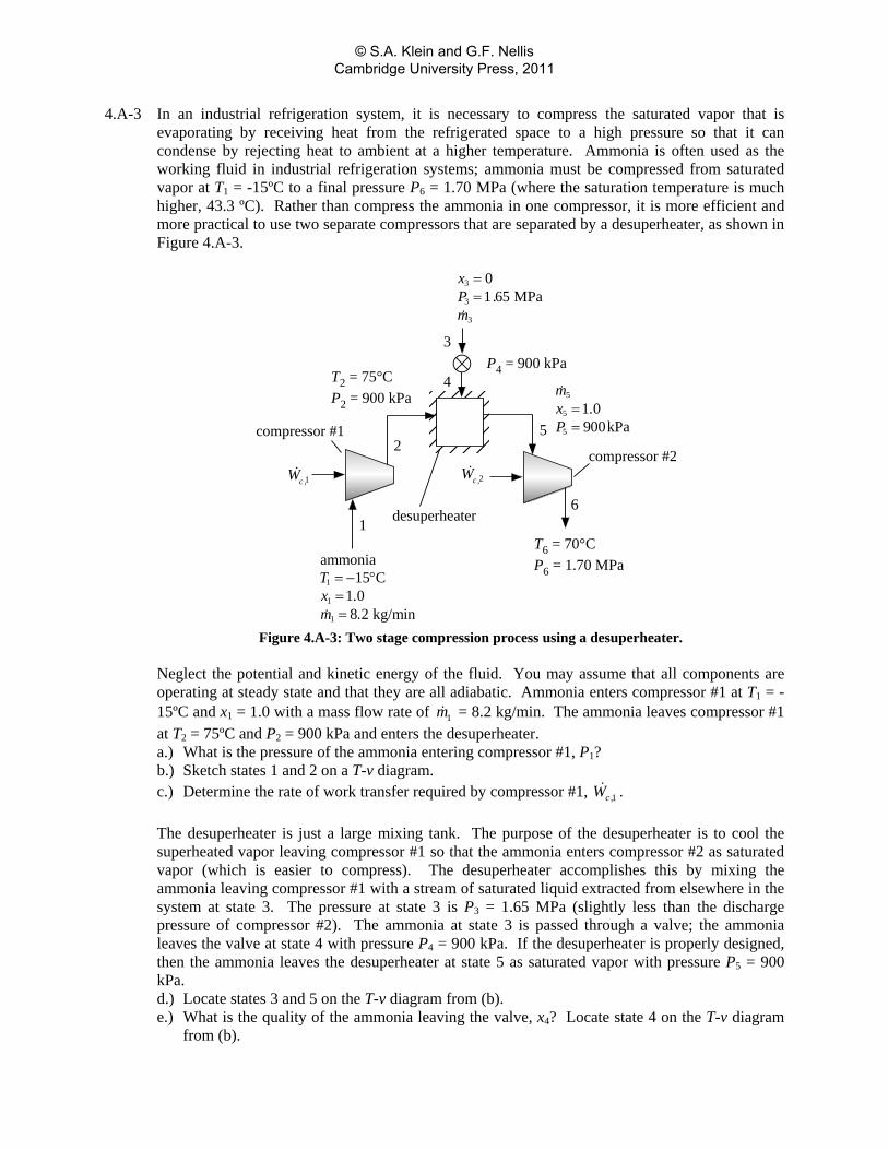
4.A-3 In an industrial refrigeration system, it is necessary to compress the saturated vapor that is evaporating by receiving heat from the refrigerated space to a high pressure so that it can condense by rejecting heat to ambient at a higher temperature. Ammonia is often used as the working fluid in industrial refrigeration systems; ammonia must be compressed from saturated vapor at T1 = -15ºC to a final pressure P6 = 1.70 MPa (where the saturation temperature is much higher, 43.3 ºC). Rather than compress the ammonia in one compressor, it is more efficient and more practical to use two separate compressors that are separated by a desuperheater, as shown in Figure 4.A-3.
compressor #1
1
1
1
ammonia15 C
1 08 2 kg/min
Tx .m .
= − °==
1c ,W 2c ,Wcompressor #2
1
2
T2 = 75°CP2 = 900 kPa
P4 = 900 kPa3
4
desuperheater
3
3
3
01 65 MPa
xP .m
==
5
5
5
5
1 0900kPa
mx .P==
T6 = 70°CP6 = 1.70 MPa
6
Figure 4.A-3: Two stage compression process using a desuperheater.
Neglect the potential and kinetic energy of the fluid. You may assume that all components are operating at steady state and that they are all adiabatic. Ammonia enters compressor #1 at T1 = -15ºC and x1 = 1.0 with a mass flow rate of 1m = 8.2 kg/min. The ammonia leaves compressor #1 at T2 = 75ºC and P2 = 900 kPa and enters the desuperheater. a.) What is the pressure of the ammonia entering compressor #1, P1? b.) Sketch states 1 and 2 on a T-v diagram. c.) Determine the rate of work transfer required by compressor #1, 1c ,W . The desuperheater is just a large mixing tank. The purpose of the desuperheater is to cool the superheated vapor leaving compressor #1 so that the ammonia enters compressor #2 as saturated vapor (which is easier to compress). The desuperheater accomplishes this by mixing the ammonia leaving compressor #1 with a stream of saturated liquid extracted from elsewhere in the system at state 3. The pressure at state 3 is P3 = 1.65 MPa (slightly less than the discharge pressure of compressor #2). The ammonia at state 3 is passed through a valve; the ammonia leaves the valve at state 4 with pressure P4 = 900 kPa. If the desuperheater is properly designed, then the ammonia leaves the desuperheater at state 5 as saturated vapor with pressure P5 = 900 kPa. d.) Locate states 3 and 5 on the T-v diagram from (b). e.) What is the quality of the ammonia leaving the valve, x4? Locate state 4 on the T-v diagram
from (b).
© S.A. Klein and G.F. Nellis Cambridge University Press, 2011
f.) What is the mass flow rate of ammonia leaving the desuperheater, 5m ? The ammonia leaving the desuperheater is sent to compressor #2 where it is compressed to P6 = 1.70 MPa. The temperature of the ammonia leaving compressor #2 is T6 = 70ºC. g.) Locate state (6) on the T-v diagram from (b). h.) What is the rate of work transfer required by compressor #2, 2c ,W ? j.) Use EES to generate a T-v diagram and verify that it is qualitatively similar to the one you
drew as you were working through the problem.
© S.A. Klein and G.F. Nellis Cambridge University Press, 2011
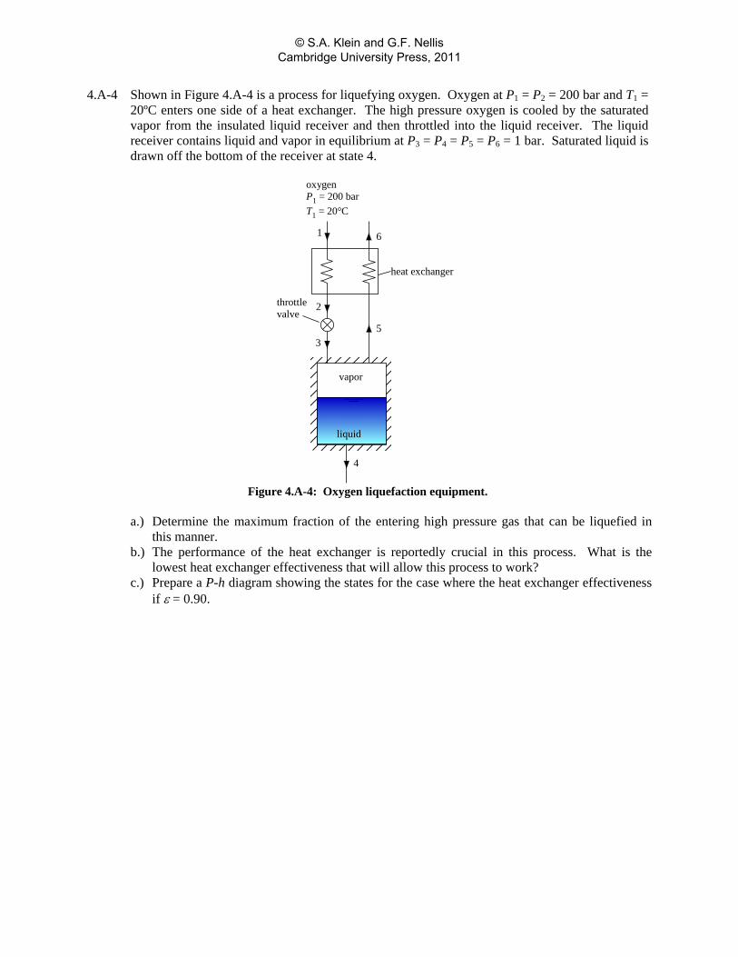
4.A-4 Shown in Figure 4.A-4 is a process for liquefying oxygen. Oxygen at P1 = P2 = 200 bar and T1 = 20ºC enters one side of a heat exchanger. The high pressure oxygen is cooled by the saturated vapor from the insulated liquid receiver and then throttled into the liquid receiver. The liquid receiver contains liquid and vapor in equilibrium at P3 = P4 = P5 = P6 = 1 bar. Saturated liquid is drawn off the bottom of the receiver at state 4.
heat exchanger
2
3
throttlevalve
61
vapor
liquid
4
5
oxygenP1 = 200 barT1 = 20°C
Figure 4.A-4: Oxygen liquefaction equipment.
a.) Determine the maximum fraction of the entering high pressure gas that can be liquefied in
this manner. b.) The performance of the heat exchanger is reportedly crucial in this process. What is the
lowest heat exchanger effectiveness that will allow this process to work? c.) Prepare a P-h diagram showing the states for the case where the heat exchanger effectiveness
if ε = 0.90.
© S.A. Klein and G.F. Nellis Cambridge University Press, 2011
4.A-5 An open feedwater heater operates at state-state conditions with liquid water entering through a D1 = 4 cm diameter pipe at P1 = 7 bar and T1 = 42°C with a mass flow rate of 1m = 70 kg/s. A separate stream of water enters the heater through a D2 = 12 cm pipe at P2 = 7 bar with a quality of x2 = 0.98. Saturated liquid at P3 = 7 bar exits the feedwater heater through a D3 = 4 cm pipe at
3m = 89.5 kg/s. The ambient temperature of the air surrounding the heater is Tamb = 20°C. a.) Calculate the rate of heat flow from the jacket of the heater. b.) Indicate whether you believe the kinetic energy of the streams is important to consider in the
energy balance. c.) Show the state points on a pressure-enthalpy diagram. d.) Estimate an overall heat transfer coefficient-area product between the feedwater heater and
the surroundings.
© S.A. Klein and G.F. Nellis Cambridge University Press, 2011
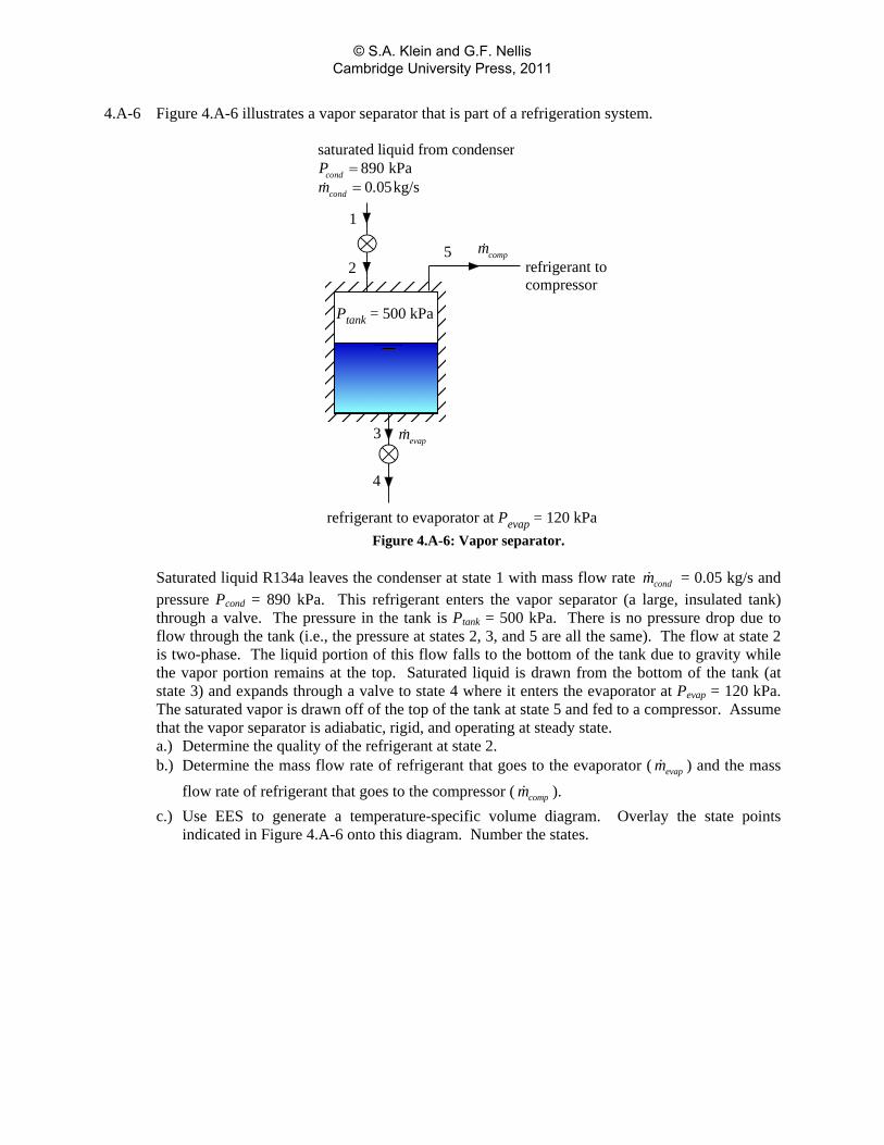
4.A-6 Figure 4.A-6 illustrates a vapor separator that is part of a refrigeration system.
saturated liquid from condenser890 kPa0 05kg/s
cond
cond
Pm .
==
1
2
3
4
5
refrigerant to evaporator at Pevap = 120 kPa
evapm
compmrefrigerant tocompressor
Ptank = 500 kPa
Figure 4.A-6: Vapor separator.
Saturated liquid R134a leaves the condenser at state 1 with mass flow rate condm = 0.05 kg/s and pressure Pcond = 890 kPa. This refrigerant enters the vapor separator (a large, insulated tank) through a valve. The pressure in the tank is Ptank = 500 kPa. There is no pressure drop due to flow through the tank (i.e., the pressure at states 2, 3, and 5 are all the same). The flow at state 2 is two-phase. The liquid portion of this flow falls to the bottom of the tank due to gravity while the vapor portion remains at the top. Saturated liquid is drawn from the bottom of the tank (at state 3) and expands through a valve to state 4 where it enters the evaporator at Pevap = 120 kPa. The saturated vapor is drawn off of the top of the tank at state 5 and fed to a compressor. Assume that the vapor separator is adiabatic, rigid, and operating at steady state. a.) Determine the quality of the refrigerant at state 2. b.) Determine the mass flow rate of refrigerant that goes to the evaporator ( evapm ) and the mass
flow rate of refrigerant that goes to the compressor ( compm ). c.) Use EES to generate a temperature-specific volume diagram. Overlay the state points
indicated in Figure 4.A-6 onto this diagram. Number the states.
© S.A. Klein and G.F. Nellis Cambridge University Press, 2011
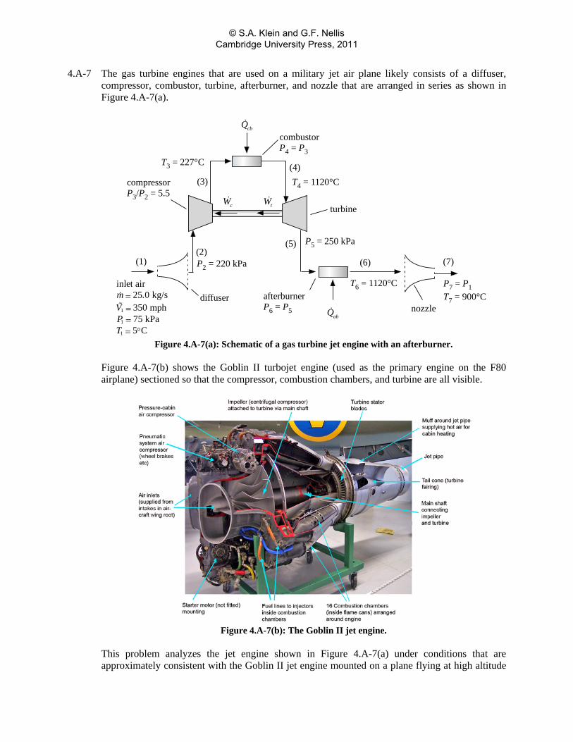
4.A-7 The gas turbine engines that are used on a military jet air plane likely consists of a diffuser, compressor, combustor, turbine, afterburner, and nozzle that are arranged in series as shown in Figure 4.A-7(a).
(1)
diffuser
(2)
compressorP3/P2 = 5.5
(3)
tW
combustorP4 = P3
cbQ
(4)T4 = 1120°C
turbine
(5)
nozzle
(6)
P7 = P1T7 = 900°C
cW
1
1
1
inlet air25 0 kg/s350 mph75 kPa5 C
m .VPT
==== °
P2 = 220 kPa
T3 = 227°C
afterburnerP6 = P5
P5 = 250 kPa
(7)
abQ
T6 = 1120°C
Figure 4.A-7(a): Schematic of a gas turbine jet engine with an afterburner.
Figure 4.A-7(b) shows the Goblin II turbojet engine (used as the primary engine on the F80 airplane) sectioned so that the compressor, combustion chambers, and turbine are all visible.
Figure 4.A-7(b): The Goblin II jet engine.
This problem analyzes the jet engine shown in Figure 4.A-7(a) under conditions that are approximately consistent with the Goblin II jet engine mounted on a plane flying at high altitude
© S.A. Klein and G.F. Nellis Cambridge University Press, 2011
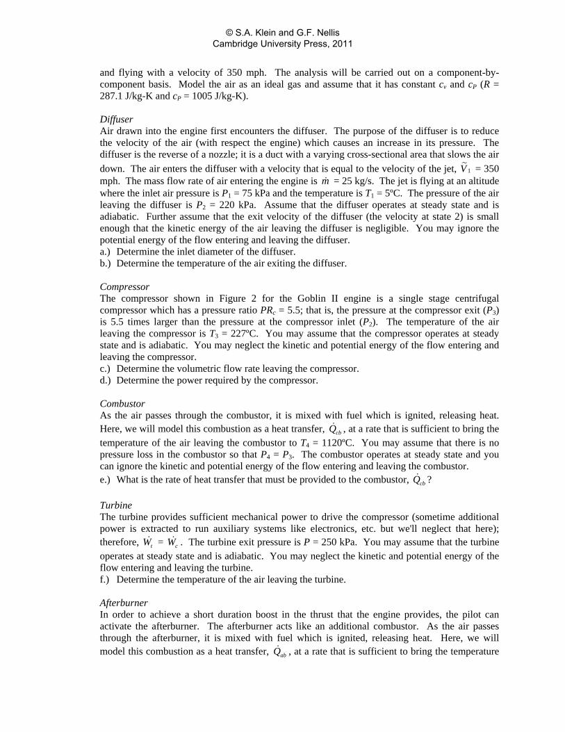
and flying with a velocity of 350 mph. The analysis will be carried out on a component-by-component basis. Model the air as an ideal gas and assume that it has constant cv and cP (R = 287.1 J/kg-K and cP = 1005 J/kg-K). Diffuser Air drawn into the engine first encounters the diffuser. The purpose of the diffuser is to reduce the velocity of the air (with respect the engine) which causes an increase in its pressure. The diffuser is the reverse of a nozzle; it is a duct with a varying cross-sectional area that slows the air down. The air enters the diffuser with a velocity that is equal to the velocity of the jet, 1V = 350 mph. The mass flow rate of air entering the engine is m = 25 kg/s. The jet is flying at an altitude where the inlet air pressure is P1 = 75 kPa and the temperature is T1 = 5ºC. The pressure of the air leaving the diffuser is P2 = 220 kPa. Assume that the diffuser operates at steady state and is adiabatic. Further assume that the exit velocity of the diffuser (the velocity at state 2) is small enough that the kinetic energy of the air leaving the diffuser is negligible. You may ignore the potential energy of the flow entering and leaving the diffuser. a.) Determine the inlet diameter of the diffuser. b.) Determine the temperature of the air exiting the diffuser.
Compressor The compressor shown in Figure 2 for the Goblin II engine is a single stage centrifugal compressor which has a pressure ratio PRc = 5.5; that is, the pressure at the compressor exit (P3) is 5.5 times larger than the pressure at the compressor inlet (P2). The temperature of the air leaving the compressor is T3 = 227ºC. You may assume that the compressor operates at steady state and is adiabatic. You may neglect the kinetic and potential energy of the flow entering and leaving the compressor. c.) Determine the volumetric flow rate leaving the compressor. d.) Determine the power required by the compressor.
Combustor As the air passes through the combustor, it is mixed with fuel which is ignited, releasing heat. Here, we will model this combustion as a heat transfer, cbQ , at a rate that is sufficient to bring the temperature of the air leaving the combustor to T4 = 1120ºC. You may assume that there is no pressure loss in the combustor so that P4 = P3. The combustor operates at steady state and you can ignore the kinetic and potential energy of the flow entering and leaving the combustor. e.) What is the rate of heat transfer that must be provided to the combustor, cbQ ?
Turbine The turbine provides sufficient mechanical power to drive the compressor (sometime additional power is extracted to run auxiliary systems like electronics, etc. but we'll neglect that here); therefore, tW = cW . The turbine exit pressure is P = 250 kPa. You may assume that the turbine operates at steady state and is adiabatic. You may neglect the kinetic and potential energy of the flow entering and leaving the turbine. f.) Determine the temperature of the air leaving the turbine.
Afterburner In order to achieve a short duration boost in the thrust that the engine provides, the pilot can activate the afterburner. The afterburner acts like an additional combustor. As the air passes through the afterburner, it is mixed with fuel which is ignited, releasing heat. Here, we will model this combustion as a heat transfer, abQ , at a rate that is sufficient to bring the temperature
© S.A. Klein and G.F. Nellis Cambridge University Press, 2011

of the air leaving the afterburner to T6 = 1120ºC. You may assume that there is no pressure loss in the afterburner so that P6 = P5. The afterburner operates at steady state and you can ignore the kinetic and potential energy of the flow entering and leaving the combustor. g.) Determine the rate of heat transfer that must be provided to the afterburner, abQ .
Nozzle The nozzle accelerates the fluid to a high velocity so that the air can be propelled out the back of the turbojet engine at a velocity that is faster than the plane itself is flying; this produces thrust (like a rocket engine). The temperature of the air leaving the nozzle is T7 = 900ºC. The nozzle exit pressure is the same as the diffuser inlet pressure, P6 = P1. You may assume that the nozzle operates at steady state and is adiabatic. You may neglect the kinetic energy of the flow entering (but not leaving) the nozzle and the potential energy of the flow entering and leaving the nozzle. h.) Determine the nozzle exit velocity. i.) Determine the exit area of the nozzle.
The whole point of a turbojet engine is to produce a thrust force that pushes the jet forward. The thrust force is given by: ( )7 1thrustF m V V= −
j.) What is the thrust force produced by this engine? (Note that the thrust rating for the Goblin II engine was about 14 kN so your answer shouldn't be too different from that).
The heat provided to the combustor and afterburner is obtained by burning fuel. The amount of fuel required can be estimated from the fuel's heat of combustion, HC, which is the ratio of the heat provided to the mass of the fuel burned. The heat of combustion of jet fuel is approximately HC = 42 MJ/kg. k.) Determine the rate at which the engine consumes fuel, fuelm .
There are two important figures of merit for a jet engine; one is the specific thrust, which is defined as the ratio of the thrust force produced by the engine to the rate at which the engine consumes fuel. l.) Determine the specific thrust of the engine (in lbf-s/lbm).
The other figure of merit for the engine is the overall efficiency. The overall efficiency is defined as the ratio of the power provided to the airplane (i.e., the product of the velocity of the airplane and the thrust) to the total rate of heat transfer to the engine. m.) Determine the overall efficiency of the engine.
© S.A. Klein and G.F. Nellis Cambridge University Press, 2011
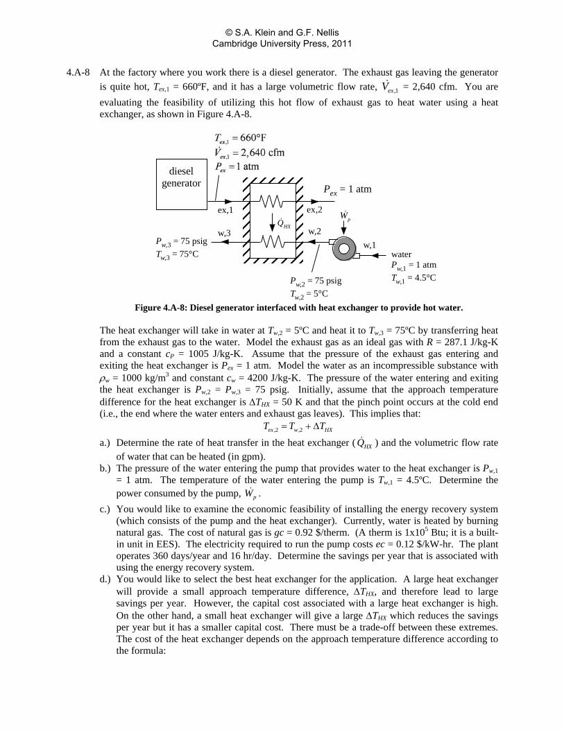
4.A-8 At the factory where you work there is a diesel generator. The exhaust gas leaving the generator is quite hot, Tex,1 = 660ºF, and it has a large volumetric flow rate, ,1exV = 2,640 cfm. You are evaluating the feasibility of utilizing this hot flow of exhaust gas to heat water using a heat exchanger, as shown in Figure 4.A-8.
dieselgenerator
ex,1 ex,2
w,1w,2w,3
waterPw,1 = 1 atmTw,1 = 4.5°C
HXQ
Pw,2 = 75 psigTw,2 = 5°C
Pw,3 = 75 psigTw,3 = 75°C
pW
Pex = 1 atm
Figure 4.A-8: Diesel generator interfaced with heat exchanger to provide hot water.
The heat exchanger will take in water at Tw,2 = 5ºC and heat it to Tw,3 = 75ºC by transferring heat from the exhaust gas to the water. Model the exhaust gas as an ideal gas with R = 287.1 J/kg-K and a constant cP = 1005 J/kg-K. Assume that the pressure of the exhaust gas entering and exiting the heat exchanger is Pex = 1 atm. Model the water as an incompressible substance with ρw = 1000 kg/m3 and constant cw = 4200 J/kg-K. The pressure of the water entering and exiting the heat exchanger is Pw,2 = Pw,3 = 75 psig. Initially, assume that the approach temperature difference for the heat exchanger is ΔTHX = 50 K and that the pinch point occurs at the cold end (i.e., the end where the water enters and exhaust gas leaves). This implies that: 2 2ex , w, HXT T T= + Δ
a.) Determine the rate of heat transfer in the heat exchanger ( HXQ ) and the volumetric flow rate of water that can be heated (in gpm).
b.) The pressure of the water entering the pump that provides water to the heat exchanger is Pw,1 = 1 atm. The temperature of the water entering the pump is Tw,1 = 4.5ºC. Determine the power consumed by the pump, pW .
c.) You would like to examine the economic feasibility of installing the energy recovery system (which consists of the pump and the heat exchanger). Currently, water is heated by burning natural gas. The cost of natural gas is gc = 0.92 $/therm. (A therm is 1x10⁵ Btu; it is a built-in unit in EES). The electricity required to run the pump costs ec = 0.12 $/kW-hr. The plant operates 360 days/year and 16 hr/day. Determine the savings per year that is associated with using the energy recovery system.
d.) You would like to select the best heat exchanger for the application. A large heat exchanger will provide a small approach temperature difference, ΔTHX, and therefore lead to large savings per year. However, the capital cost associated with a large heat exchanger is high. On the other hand, a small heat exchanger will give a large ΔTHX which reduces the savings per year but it has a smaller capital cost. There must be a trade-off between these extremes. The cost of the heat exchanger depends on the approach temperature difference according to the formula:
© S.A. Klein and G.F. Nellis Cambridge University Press, 2011
HXHX
aCostT
=Δ
where a = 5x10⁵ $-K. Determine the net savings associated with purchasing and operating the system for Nyear = 3 years. Neglect the time value of money in your analysis.
e.) Plot the net savings associated with purchasing and operating the system system for Nyear = 3 years as a function of ΔTHX. You should see that there is an economically optimal heat exchanger for this application.
© S.A. Klein and G.F. Nellis Cambridge University Press, 2011
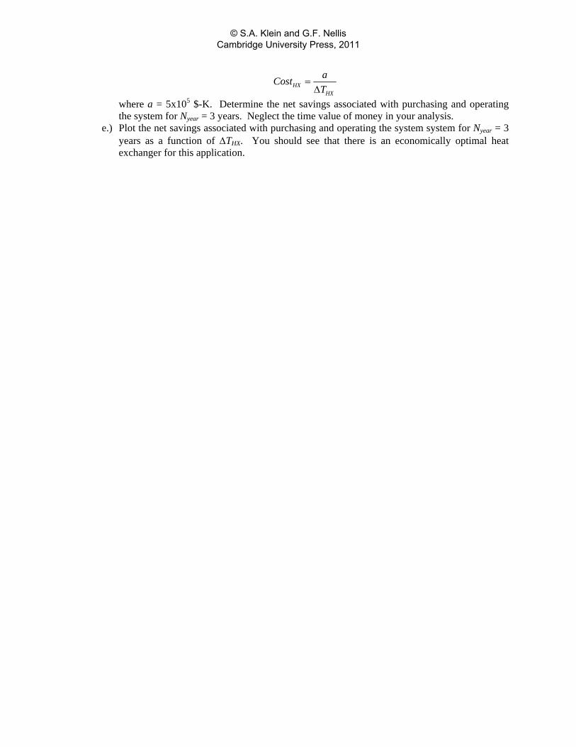
4.A-9 A steam turbine is used to drive an R134a compressor and a generator at steady conditions, as shown in Figure 4.A-9. The steam enters the turbine at P1 = 4MPa, T1 = 350°C, stmm 0.125 kg/s and exits at P2 = 20 kPa with a quality x2 = 0.95. The R134a enters the compressor at P3 = 100 kPa, T3 = 20°C, Rm = 0.25 kg/s. After leaving the compressor at T4 = 150°C, the R134a passes through an aftercooler and emerges at P5 = 2.0 MPa and T5 = 80°C. Assume that the compressor and turbine both operate adiabatically and neglect pressure losses in the aftercooler.
compressorturbine generator
1
1
steam4 MPa350 C
0 125 kg/sstm
PTm .
== °=
1
aftercooler
2
P2 = 20 kPax2 = 0.95
generatedpower
3
3
3
R134a100 kPa20 C0 25 kg/sR
PTm .
== °=
4
T4 = 150°C
5P5 = 2 MPaT5 = 80°C
Figure 4.A-9: Steam driven compressor and generator.
a.) Determine the power delivered to the compressor. b.) Determine the power provided to the generator. c.) Determine the rate of heat transfer from the aftercooler.
© S.A. Klein and G.F. Nellis Cambridge University Press, 2011
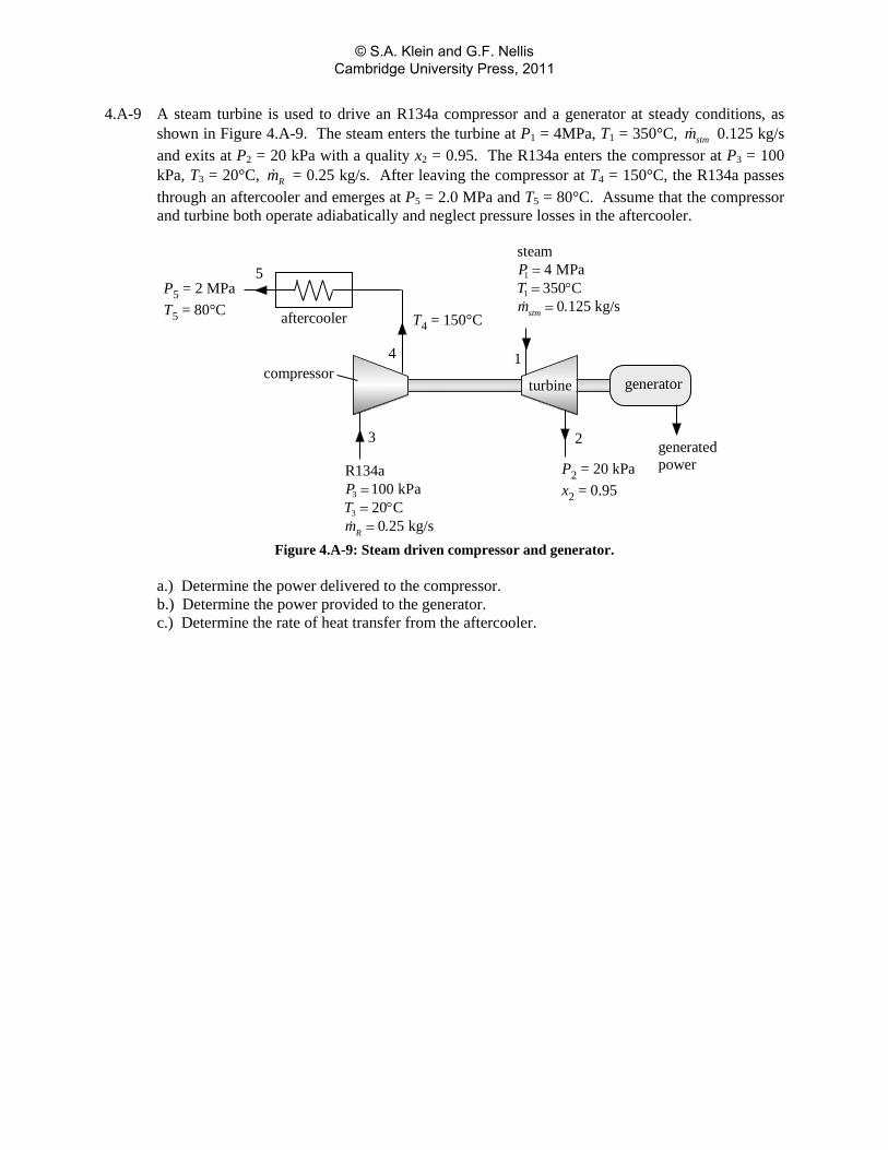
4.A-10 Steam enters a turbine at 1m = 600 lbm/hr, P1 = 500 psia, and T1 = 700°F with negligible velocity. Two exit streams leave the turbine, as indicated in Figure 4.A-10. Stream 2 exits at P2 = 200 psia, T2 = 400°F with a flow rate of 2m = 200 lbm/hr and a velocity of 2V = 800 ft/s. Stream 3 exits at P3 = 150 psia with negligible velocity and it is suspected to be in a saturated state. A small sample of stream 3 is passed through a well-insulated throttling valve and exits as state 4 at P4 = 1 atm and T4 = 250°F.
turbine generated power
1
23
4
1 m
1
1
600 lb /hr500 psia700 F
mPT
=== °
2 m
2
2
2
200 lb /hr200 psia400 F800 ft/s
mPTV
=== °=
P3 = 150 psia
P4 = 1 atmT4 = 250°F
Figure 4.A-10: Turbine with throttling calorimeter.
a.) Determine the quality of the steam at state 3. b.) Determine the power output of this turbine (in hp) assuming it operates adiabatically.
© S.A. Klein and G.F. Nellis Cambridge University Press, 2011
4.A-11 In the evaporator of an air conditioning system, dry air at airm = 0.75 kg/s, Tair,in = 40°C and Pair,in = 1.04 bar passes over finned tubes through which refrigerant R134a flows. The air exits the evaporator at Tair,out = 25°C and Pair,out = 1.01 bar. The refrigerant enters the tubes with a quality of xin = 0.2 and temperature TR = 12°C and exits as saturated vapor at the same temperature. The jacket of the evaporator is well-insulated. a.) Determine the volumetric flow rate of the air. b.) Determine the mass flow rate of the refrigerant. c.) Determine the rate of energy transfer from the air to the refrigerant. d.) Before entering the heat exchanger, the refrigerant existed as saturated liquid, which was then
throttled through an expansion valve to the evaporator pressure. Determine the pressure and temperature of the saturated liquid refrigerant upstream of the valve.
© S.A. Klein and G.F. Nellis Cambridge University Press, 2011
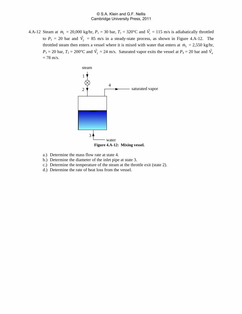
4.A-12 Steam at 1m = 20,000 kg/hr, P1 = 30 bar, T1 = 320°C and 1V = 115 m/s is adiabatically throttled to P1 = 20 bar and 2V = 85 m/s in a steady-state process, as shown in Figure 4.A-12. The throttled steam then enters a vessel where it is mixed with water that enters at 3m = 2,550 kg/hr, P3 = 20 bar, T3 = 200°C and 3V = 24 m/s. Saturated vapor exits the vessel at P4 = 20 bar and 4V = 78 m/s.
1
2
3
4
steam
saturated vapor
water Figure 4.A-12: Mixing vessel.
a.) Determine the mass flow rate at state 4. b.) Determine the diameter of the inlet pipe at state 3. c.) Determine the temperature of the steam at the throttle exit (state 2). d.) Determine the rate of heat loss from the vessel.
© S.A. Klein and G.F. Nellis Cambridge University Press, 2011
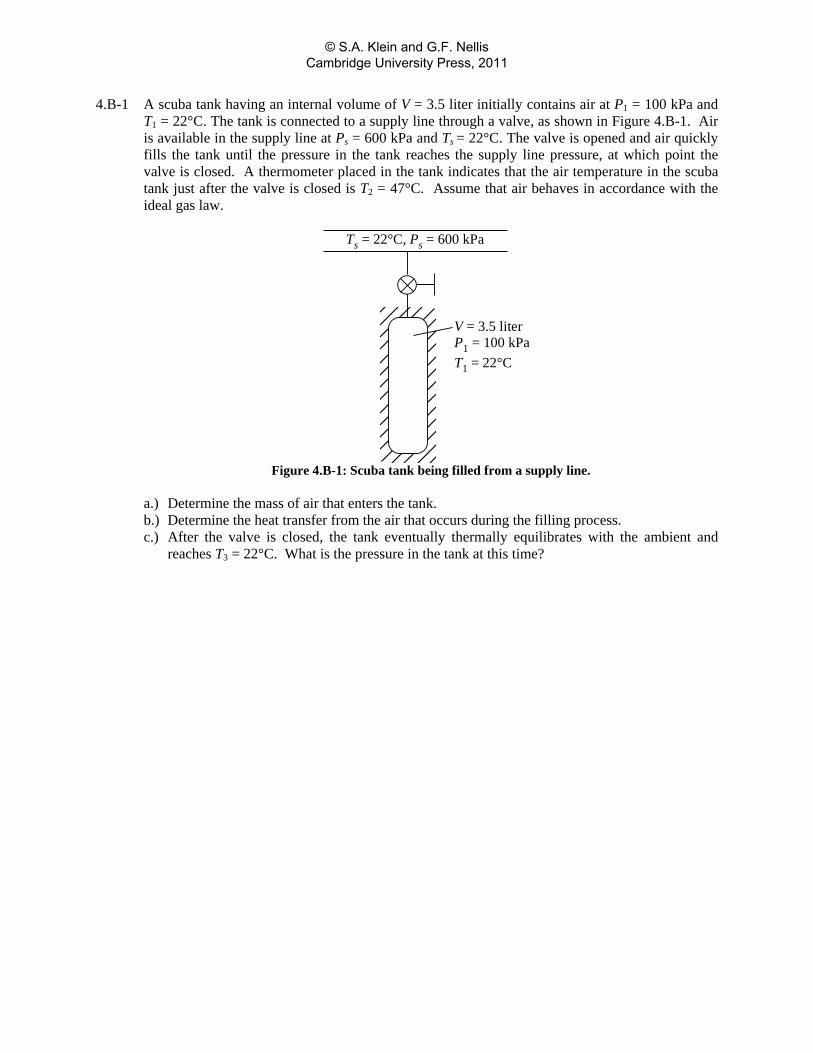
4.B-1 A scuba tank having an internal volume of V = 3.5 liter initially contains air at P1 = 100 kPa and T1 = 22°C. The tank is connected to a supply line through a valve, as shown in Figure 4.B-1. Air is available in the supply line at Ps = 600 kPa and Ts = 22°C. The valve is opened and air quickly fills the tank until the pressure in the tank reaches the supply line pressure, at which point the valve is closed. A thermometer placed in the tank indicates that the air temperature in the scuba tank just after the valve is closed is T2 = 47°C. Assume that air behaves in accordance with the ideal gas law.
V = 3.5 literP1 = 100 kPaT1 = 22°C
Ts = 22°C, Ps = 600 kPa
Figure 4.B-1: Scuba tank being filled from a supply line.
a.) Determine the mass of air that enters the tank. b.) Determine the heat transfer from the air that occurs during the filling process. c.) After the valve is closed, the tank eventually thermally equilibrates with the ambient and
reaches T3 = 22°C. What is the pressure in the tank at this time?
© S.A. Klein and G.F. Nellis Cambridge University Press, 2011
4.B-2 A rigid tank with internal volume V = 0.3 m3 is filled with saturated liquid water at T = 200°C. A valve at the bottom of the tank is opened, and saturated liquid only is withdrawn from the tank. Heat is transferred to the water in the tank so that the temperature of the water remains constant during this process. The process is complete when half of the total mass of water in the tank is withdrawn. a.) Determine the quality at the final state. b.) Determine the amount of heat that must be transferred to the water in the tank.
© S.A. Klein and G.F. Nellis Cambridge University Press, 2011
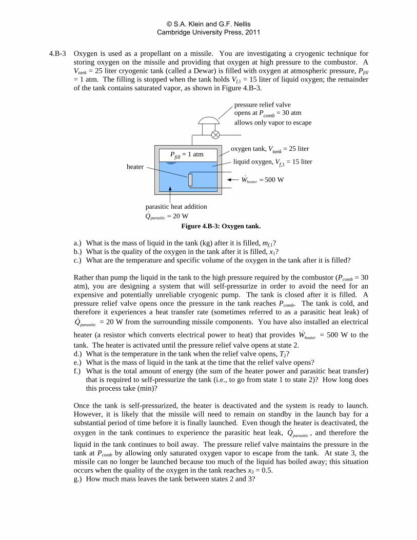
4.B-3 Oxygen is used as a propellant on a missile. You are investigating a cryogenic technique for storing oxygen on the missile and providing that oxygen at high pressure to the combustor. A Vtank = 25 liter cryogenic tank (called a Dewar) is filled with oxygen at atmospheric pressure, Pfill = 1 atm. The filling is stopped when the tank holds Vf,1 = 15 liter of liquid oxygen; the remainder of the tank contains saturated vapor, as shown in Figure 4.B-3.
500 WheaterW =
heater
pressure relief valveopens at Pcomb = 30 atmallows only vapor to escape
parasitic heat addition20 WparasiticQ =
oxygen tank, Vtank = 25 liter
liquid oxygen, Vf,1 = 15 literPfill = 1 atm
Figure 4.B-3: Oxygen tank.
a.) What is the mass of liquid in the tank (kg) after it is filled, mf,1? b.) What is the quality of the oxygen in the tank after it is filled, x1? c.) What are the temperature and specific volume of the oxygen in the tank after it is filled? Rather than pump the liquid in the tank to the high pressure required by the combustor (Pcomb = 30 atm), you are designing a system that will self-pressurize in order to avoid the need for an expensive and potentially unreliable cryogenic pump. The tank is closed after it is filled. A pressure relief valve opens once the pressure in the tank reaches Pcomb. The tank is cold, and therefore it experiences a heat transfer rate (sometimes referred to as a parasitic heat leak) of
parasiticQ = 20 W from the surrounding missile components. You have also installed an electrical
heater (a resistor which converts electrical power to heat) that provides heaterW = 500 W to the tank. The heater is activated until the pressure relief valve opens at state 2. d.) What is the temperature in the tank when the relief valve opens, T2? e.) What is the mass of liquid in the tank at the time that the relief valve opens? f.) What is the total amount of energy (the sum of the heater power and parasitic heat transfer)
that is required to self-pressurize the tank (i.e., to go from state 1 to state 2)? How long does this process take (min)?
Once the tank is self-pressurized, the heater is deactivated and the system is ready to launch. However, it is likely that the missile will need to remain on standby in the launch bay for a substantial period of time before it is finally launched. Even though the heater is deactivated, the oxygen in the tank continues to experience the parasitic heat leak, parasiticQ , and therefore the liquid in the tank continues to boil away. The pressure relief valve maintains the pressure in the tank at Pcomb by allowing only saturated oxygen vapor to escape from the tank. At state 3, the missile can no longer be launched because too much of the liquid has boiled away; this situation occurs when the quality of the oxygen in the tank reaches x3 = 0.5. g.) How much mass leaves the tank between states 2 and 3?
© S.A. Klein and G.F. Nellis Cambridge University Press, 2011

h.) What is the total amount of heat transfer required to go from state 2 to state 3? i.) How long can the missile sit in the launch bay without being fired before the oxygen tank will
need to be refilled (hr)? j.) Generate a T-v diagram using EES and overlay your states onto this diagram.
© S.A. Klein and G.F. Nellis Cambridge University Press, 2011
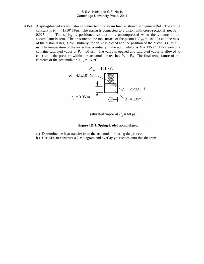
4.B-4 A spring-loaded accumulator is connected to a steam line, as shown in Figure 4.B-4. The spring constant is K = 4.1x10⁴ N/m. The spring is connected to a piston with cross-sectional area Ap = 0.025 m2. The spring is positioned so that it is uncompressed when the volume in the accumulator is zero. The pressure on the top surface of the piston is Patm = 101 kPa and the mass of the piston is negligible. Initially, the valve is closed and the position of the piston is z1 = 0.05 m. The temperature of the water that is initially in the accumulator is T1 = 135°C. The steam line contains saturated vapor at Ps = 60 psi. The valve is opened and saturated vapor is allowed to enter until the pressure within the accumulator reaches P2 = Ps. The final temperature of the contents of the accumulator is T2 = 150°C.
saturated vapor at Ps = 60 psi
Patm = 101 kPa
K = 4.1x10⁴ N/m
z1 = 0.05 m
Ap = 0.025 m2
T1 = 135°C
Figure 4.B-4: Spring-loaded accumulator.
a.) Determine the heat transfer from the accumulator during the process. b.) Use EES to construct a T-v diagram and overlay your states onto this diagram.
© S.A. Klein and G.F. Nellis Cambridge University Press, 2011
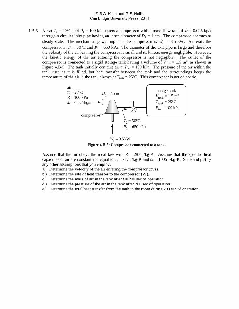
4.B-5 Air at T1 = 20°C and P1 = 100 kPa enters a compressor with a mass flow rate of m = 0.025 kg/s through a circular inlet pipe having an inner diameter of D1 = 1 cm. The compressor operates at steady state. The mechanical power input to the compressor is cW = 3.5 kW. Air exits the compressor at T2 = 50°C and P2 = 650 kPa. The diameter of the exit pipe is large and therefore the velocity of the air leaving the compressor is small and its kinetic energy negligible. However, the kinetic energy of the air entering the compressor is not negligible. The outlet of the compressor is connected to a rigid storage tank having a volume of Vtank = 1.5 m3, as shown in Figure 4.B-5. The tank initially contains air at Pini = 100 kPa. The pressure of the air within the tank rises as it is filled, but heat transfer between the tank and the surroundings keeps the temperature of the air in the tank always at Ttank = 25ºC. This compressor is not adiabatic.
D1 = 1 cm
compressor
storage tankVtank = 1.5 m3
Ttank = 25°CPini = 100 kPa
T2 = 50°CP2 = 650 kPa
1
1
air20 C100 kPa0.025kg/s
TPm
= °==
3.5kWcW = Figure 4.B-5: Compressor connected to a tank.
Assume that the air obeys the ideal law with R = 287 J/kg-K. Assume that the specific heat capacities of air are constant and equal to cv = 717 J/kg-K and cP = 1005 J/kg-K. State and justify any other assumptions that you employ. a.) Determine the velocity of the air entering the compressor (m/s). b.) Determine the rate of heat transfer to the compressor (W). c.) Determine the mass of air in the tank after t = 200 sec of operation. d.) Determine the pressure of the air in the tank after 200 sec of operation. e.) Determine the total heat transfer from the tank to the room during 200 sec of operation.
© S.A. Klein and G.F. Nellis Cambridge University Press, 2011
4.B-6 An externally insulated hydrogen liquid storage tank made of stainless steel has just been drained and the walls and residual gas are at the atmospheric boiling point of hydrogen. The pressure in the tank is initially at P1 = 1 atm. The tank is connected to a supply of higher pressure hydrogen gas at Ts = 25°C and Ps = 7.5 bar. The tank is very rapidly pressurized to P2 = Ps. The tank is then held at this pressure by allowing additional gas to enter until the gas and walls are at the same temperature. The internal volume of the tank is V = 0.30 m3 and the empty tank mass is mt = 130 kg. The specific heat capacity of the tank material should be modeled using the equation:
20 1 2c a a T a T= + +
where c has units J/kg-K and T has units K. The coefficients are a0 = 38.31 J/kg-K, a1 = -1.851 J/kg-K2, and a2 = 4.685x10⁻² J/kg-K3. a.) What is the final temperature?
© S.A. Klein and G.F. Nellis Cambridge University Press, 2011
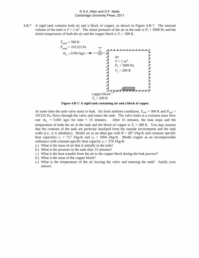
4.B-7 A rigid tank contains both air and a block of copper, as shown in Figure 4.B-7. The internal volume of the tank is V = 1 m3. The initial pressure of the air in the tank is P1 = 5000 Pa and the initial temperature of both the air and the copper block is T1 = 200 K.
airV = 1 m3
P1 = 5000 PaT1 = 200 K
copper blockT1 = 200 K
Tamb = 300 KPamb = 101325 Pa
0 001 kg/sinm .=
Figure 4.B-7: A rigid tank containing air and a block of copper.
At some time the tank valve starts to leak. Air from ambient conditions, Tamb = 300 K and Pamb = 101325 Pa, flows through the valve and enters the tank. The valve leaks at a constant mass flow rate inm = 0.001 kg/s for time = 15 minutes. After 15 minutes, the leak stops and the temperature of both the air in the tank and the block of copper is T2 = 280 K. You may assume that the contents of the tank are perfectly insulated from the outside environment and the tank walls (i.e., it is adiabatic). Model air as an ideal gas with R = 287 J/kg-K and constant specific heat capacities cv = 717 J/kg-K and cP = 1004 J/kg-K. Model copper as an incompressible substance with constant specific heat capacity cb = 370 J/kg-K. a.) What is the mass of air that is initially in the tank? b.) What is the pressure in the tank after 15 minutes? c.) What is the heat transfer from the air to the copper block during the leak process? d.) What is the mass of the copper block? e.) What is the temperature of the air leaving the valve and entering the tank? Justify your
answer.
© S.A. Klein and G.F. Nellis Cambridge University Press, 2011
4.B-8 Dear Professor I’m embarrassed to admit it, but 8 years away from doing any calculations remotely complicated has left me depleted of my integral calculus skills. I remember doing a similar but more complicated calculation in your thermodynamics class at some point, but I can’t, for the life of me, remember how to set it up or solve it and I can’t find it in the notes I saved for reference. I don’t want to waste your time but if you could help a helpless engineer out when you get a chance, I’d be grateful.
I’ve got a leaking medical gas (oxygen) system that I’m trying to figure out the leakage rate of. The system has a total internal volume of 3.9 cu.ft. The atmospheric pressure is 12.5 psia. The initial system pressure is 62.5 psia and the final system pressure (10 minutes later) is 46.5 psia. I’m assuming that the average temperature of the oxygen in the tank stayed nearly constant at 70°F on the test day, but I did not take any temperature measurements. I’m trying to figure out what the oxygen leakage rate (in scfm) is when the system pressure is 62.5 psia. I know that non-compressible flow rate through a fixed orifice equation usually takes the form of V_dot = CD * sqrt(P) but I think that’s throwing me off here. I was hoping to even brush up on my analysis skills by working this out in the EES environment, but I can’t even get an integrand form figured out. Pathetic, I know. Do you think that it matters if oxygen temperature does not remain at 70°F? Can you help me get started?
Let’s try to help out.
a) Determine the discharge coefficient (CD) and oxygen leakage rate in scfm (standard cubic feet per minute) at 62.5 psia assuming that the tank contents are isothermal
b.) Repeat your calculations assuming that the tank contents are adiabatic.
© S.A. Klein and G.F. Nellis Cambridge University Press, 2011
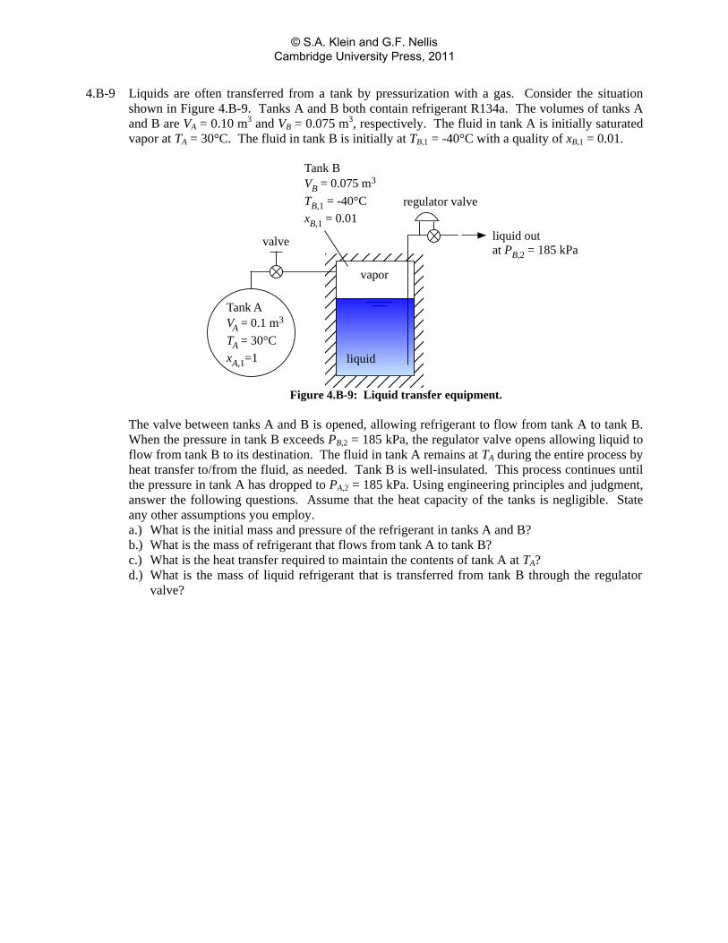
4.B-9 Liquids are often transferred from a tank by pressurization with a gas. Consider the situation shown in Figure 4.B-9. Tanks A and B both contain refrigerant R134a. The volumes of tanks A and B are VA = 0.10 m3 and VB = 0.075 m3, respectively. The fluid in tank A is initially saturated vapor at TA = 30°C. The fluid in tank B is initially at TB,1 = -40°C with a quality of xB,1 = 0.01.
Tank AVA = 0.1 m3
TA = 30°CxA,1=1
vapor
liquid
Tank BVB = 0.075 m3
TB,1 = -40°CxB,1 = 0.01
valve
regulator valve
liquid outat PB,2 = 185 kPa
Figure 4.B-9: Liquid transfer equipment.
The valve between tanks A and B is opened, allowing refrigerant to flow from tank A to tank B.
When the pressure in tank B exceeds PB,2 = 185 kPa, the regulator valve opens allowing liquid to flow from tank B to its destination. The fluid in tank A remains at TA during the entire process by heat transfer to/from the fluid, as needed. Tank B is well-insulated. This process continues until the pressure in tank A has dropped to PA,2 = 185 kPa. Using engineering principles and judgment, answer the following questions. Assume that the heat capacity of the tanks is negligible. State any other assumptions you employ. a.) What is the initial mass and pressure of the refrigerant in tanks A and B? b.) What is the mass of refrigerant that flows from tank A to tank B? c.) What is the heat transfer required to maintain the contents of tank A at TA? d.) What is the mass of liquid refrigerant that is transferred from tank B through the regulator
valve?
© S.A. Klein and G.F. Nellis Cambridge University Press, 2011
4.B-10 Liquid nitrogen is stored in a spherical Dewar tank that has an inner diameter of D = 0.7 m. The tank is initially filled so that fliq,1 = 50% of the volume is liquid. The tank is equipped with a pressure regulator that is set to Preg = 250 kPa. Vapor escapes from the tank through the regulator valve as needed to maintain this pressure in the tank. The liquid nitrogen is stored for period = 1 week (168 hours). At the end of this period, the volume of liquid in the tank is fliq,2 = 42%. a.) Determine the rate of heat transfer to the nitrogen.
© S.A. Klein and G.F. Nellis Cambridge University Press, 2011
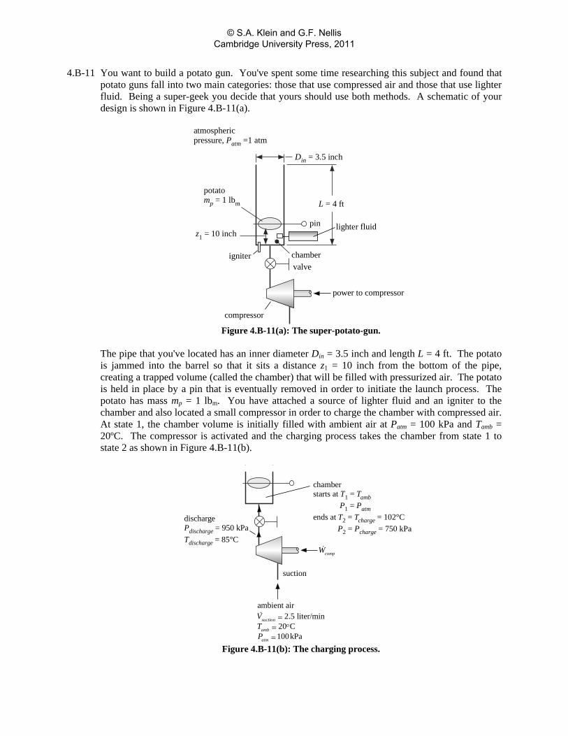
4.B-11 You want to build a potato gun. You've spent some time researching this subject and found that potato guns fall into two main categories: those that use compressed air and those that use lighter fluid. Being a super-geek you decide that yours should use both methods. A schematic of your design is shown in Figure 4.B-11(a).
z1 = 10 inch
L = 4 ft
Din = 3.5 inch
atmosphericpressure, Patm =1 atm
chambervalve
potatomp = 1 lbm
pin lighter fluid
igniter
power to compressor
compressor
Figure 4.B-11(a): The super-potato-gun. The pipe that you've located has an inner diameter Din = 3.5 inch and length L = 4 ft. The potato is jammed into the barrel so that it sits a distance z1 = 10 inch from the bottom of the pipe, creating a trapped volume (called the chamber) that will be filled with pressurized air. The potato is held in place by a pin that is eventually removed in order to initiate the launch process. The potato has mass mp = 1 lbm. You have attached a source of lighter fluid and an igniter to the chamber and also located a small compressor in order to charge the chamber with compressed air. At state 1, the chamber volume is initially filled with ambient air at Patm = 100 kPa and Tamb = 20ºC. The compressor is activated and the charging process takes the chamber from state 1 to state 2 as shown in Figure 4.B-11(b).
dischargePdischarge = 950 kPaTdischarge = 85°C
suction
ambient air2.5 liter/min
20 C100kPa
suction
amb
atm
VTP
== °=
compW
chamberstarts at T1 = Tamb
P1 = Patmends at T2 = Tcharge = 102°C
P2 = Pcharge = 750 kPa
Figure 4.B-11(b): The charging process.
© S.A. Klein and G.F. Nellis Cambridge University Press, 2011
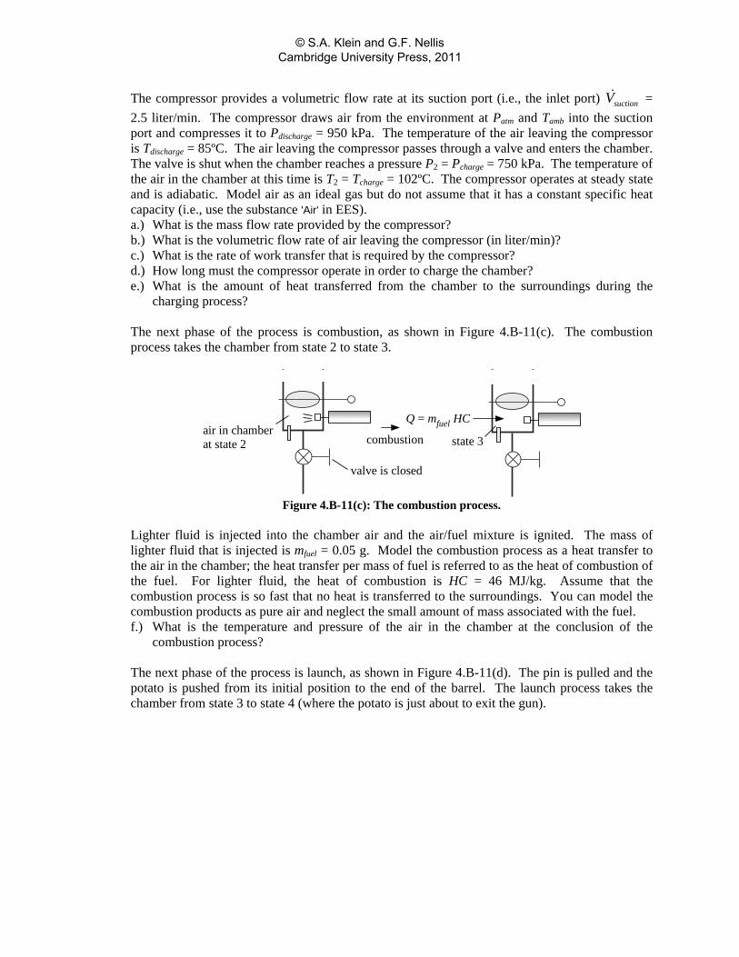
The compressor provides a volumetric flow rate at its suction port (i.e., the inlet port) suctionV = 2.5 liter/min. The compressor draws air from the environment at Patm and Tamb into the suction port and compresses it to Pdischarge = 950 kPa. The temperature of the air leaving the compressor is Tdischarge = 85ºC. The air leaving the compressor passes through a valve and enters the chamber. The valve is shut when the chamber reaches a pressure P2 = Pcharge = 750 kPa. The temperature of the air in the chamber at this time is T2 = Tcharge = 102ºC. The compressor operates at steady state and is adiabatic. Model air as an ideal gas but do not assume that it has a constant specific heat capacity (i.e., use the substance 'Air' in EES). a.) What is the mass flow rate provided by the compressor? b.) What is the volumetric flow rate of air leaving the compressor (in liter/min)? c.) What is the rate of work transfer that is required by the compressor? d.) How long must the compressor operate in order to charge the chamber? e.) What is the amount of heat transferred from the chamber to the surroundings during the
charging process?
The next phase of the process is combustion, as shown in Figure 4.B-11(c). The combustion process takes the chamber from state 2 to state 3.
Q = mfuel HC
valve is closed
air in chamberat state 2 state 3combustion
Figure 4.B-11(c): The combustion process.
Lighter fluid is injected into the chamber air and the air/fuel mixture is ignited. The mass of lighter fluid that is injected is mfuel = 0.05 g. Model the combustion process as a heat transfer to the air in the chamber; the heat transfer per mass of fuel is referred to as the heat of combustion of the fuel. For lighter fluid, the heat of combustion is HC = 46 MJ/kg. Assume that the combustion process is so fast that no heat is transferred to the surroundings. You can model the combustion products as pure air and neglect the small amount of mass associated with the fuel. f.) What is the temperature and pressure of the air in the chamber at the conclusion of the
combustion process?
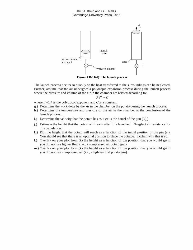
The next phase of the process is launch, as shown in Figure 4.B-11(d). The pin is pulled and the potato is pushed from its initial position to the end of the barrel. The launch process takes the chamber from state 3 to state 4 (where the potato is just about to exit the gun).
© S.A. Klein and G.F. Nellis Cambridge University Press, 2011
valve is closed
air in chamberat state 3 state 4
launch
pV
Figure 4.B-11(d): The launch process.
The launch process occurs so quickly so the heat transferred to the surroundings can be neglected. Further, assume that the air undergoes a polytropic expansion process during the launch process where the pressure and volume of the air in the chamber are related according to: nPV C= where n =1.4 is the polytropic exponent and C is a constant. g.) Determine the work done by the air in the chamber on the potato during the launch process. h.) Determine the temperature and pressure of the air in the chamber at the conclusion of the
launch process. i.) Determine the velocity that the potato has as it exits the barrel of the gun ( pV ). j.) Estimate the height that the potato will reach after it is launched. Nneglect air resistance for
this calculation. k.) Plot the height that the potato will reach as a function of the initial position of the pin (z1).
You should see that there is an optimal position to place the potatoe. Explain why this is so. l.) Overlay on your plot from (k) the height as a function of pin position that you would get if
you did not use lighter fluid (i.e., a compressed air potato gun). m.) Overlay on your plot form (k) the height as a function of pin position that you would get if
you did not use compressed air (i.e., a lighter-fluid potato gun).
© S.A. Klein and G.F. Nellis Cambridge University Press, 2011
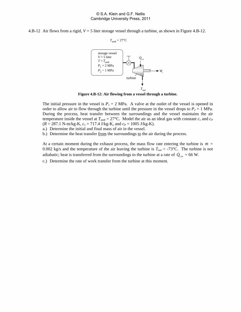
4.B-12 Air flows from a rigid, V = 5 liter storage vessel through a turbine, as shown in Figure 4.B-12.
storage vesselV = 5 literT = TambP1 = 2 MPaP2 = 1 MPa
turbine
tW
Tout
t ,inQ
Tamb = 27°C
Figure 4.B-12: Air flowing from a vessel through a turbine.
The initial pressure in the vessel is P1 = 2 MPa. A valve at the outlet of the vessel is opened in order to allow air to flow through the turbine until the pressure in the vessel drops to P2 = 1 MPa. During the process, heat transfer between the surroundings and the vessel maintains the air temperature inside the vessel at Tamb = 27°C. Model the air as an ideal gas with constant cv and cP (R = 287.1 N-m/kg-K, cv = 717.4 J/kg-K, and cP = 1005 J/kg-K). a.) Determine the initial and final mass of air in the vessel. b.) Determine the heat transfer from the surroundings to the air during the process. At a certain moment during the exhaust process, the mass flow rate entering the turbine is m = 0.002 kg/s and the temperature of the air leaving the turbine is Tout = -73°C. The turbine is not adiabatic; heat is transferred from the surroundings to the turbine at a rate of t ,inQ = 66 W. c.) Determine the rate of work transfer from the turbine at this moment.
© S.A. Klein and G.F. Nellis Cambridge University Press, 2011
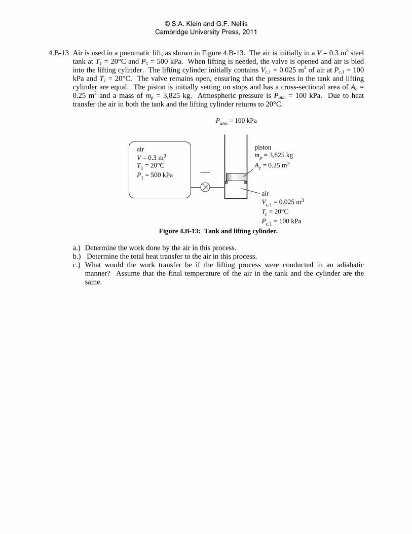
4.B-13 Air is used in a pneumatic lift, as shown in Figure 4.B-13. The air is initially in a V = 0.3 m3 steel tank at T1 = 20°C and P1 = 500 kPa. When lifting is needed, the valve is opened and air is bled into the lifting cylinder. The lifting cylinder initially contains Vc,1 = 0.025 m3 of air at Pc,1 = 100 kPa and Tc = 20°C. The valve remains open, ensuring that the pressures in the tank and lifting cylinder are equal. The piston is initially setting on stops and has a cross-sectional area of Ac = 0.25 m2 and a mass of mp = 3,825 kg. Atmospheric pressure is Patm = 100 kPa. Due to heat transfer the air in both the tank and the lifting cylinder returns to 20°C.
airV = 0.3 m3
T1 = 20°CP1 = 500 kPa
Patm = 100 kPa
pistonmp = 3,825 kgAc = 0.25 m2
airVc,1 = 0.025 m3
Tc = 20°CPc,1 = 100 kPa
Figure 4.B-13: Tank and lifting cylinder. a.) Determine the work done by the air in this process. b.) Determine the total heat transfer to the air in this process. c.) What would the work transfer be if the lifting process were conducted in an adiabatic
manner? Assume that the final temperature of the air in the tank and the cylinder are the same.
© S.A. Klein and G.F. Nellis Cambridge University Press, 2011
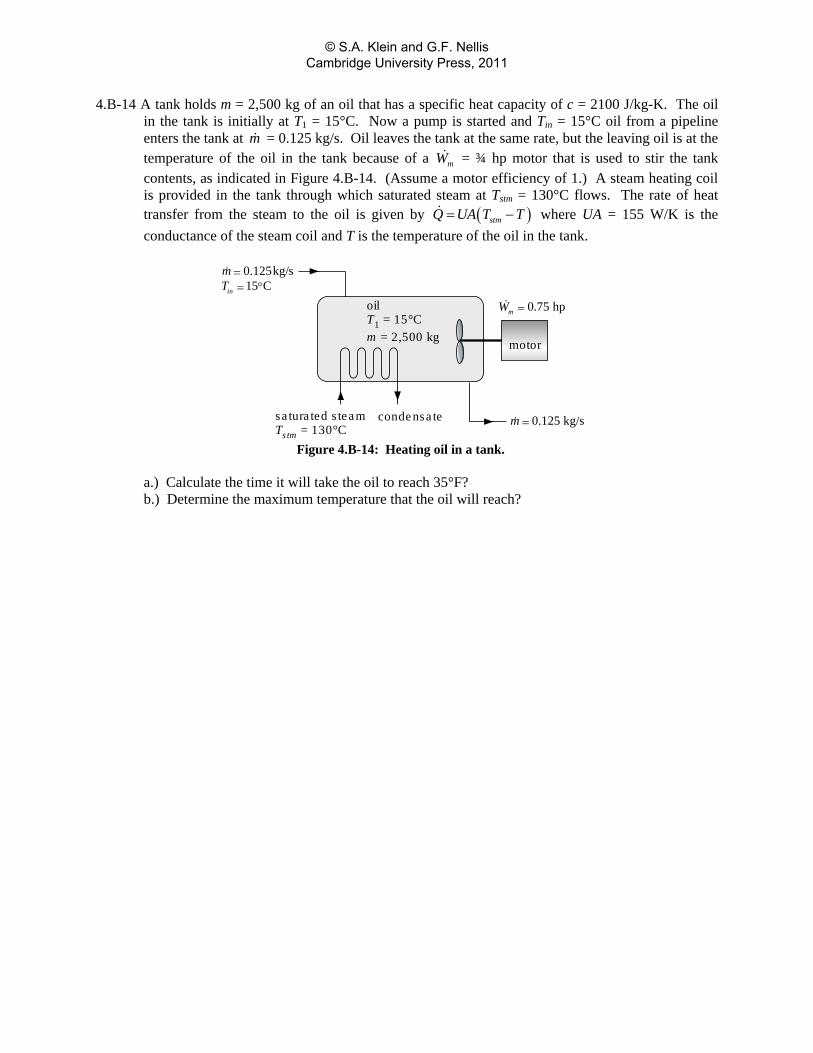
4.B-14 A tank holds m = 2,500 kg of an oil that has a specific heat capacity of c = 2100 J/kg-K. The oil in the tank is initially at T1 = 15°C. Now a pump is started and Tin = 15°C oil from a pipeline enters the tank at m = 0.125 kg/s. Oil leaves the tank at the same rate, but the leaving oil is at the temperature of the oil in the tank because of a mW = ¾ hp motor that is used to stir the tank contents, as indicated in Figure 4.B-14. (Assume a motor efficiency of 1.) A steam heating coil is provided in the tank through which saturated steam at Tstm = 130°C flows. The rate of heat transfer from the steam to the oil is given by ( )stmQ UA T T= − where UA = 155 W/K is the conductance of the steam coil and T is the temperature of the oil in the tank.
0.75 hpmW =
motor
oilT1 = 15°Cm = 2,500 kg
sa tura ted s teamTstm = 130°C
condensa te
0.125kg/s15 Cin
mT== °
0.125 kg/sm =
Figure 4.B-14: Heating oil in a tank.
a.) Calculate the time it will take the oil to reach 35°F? b.) Determine the maximum temperature that the oil will reach?
© S.A. Klein and G.F. Nellis Cambridge University Press, 2011
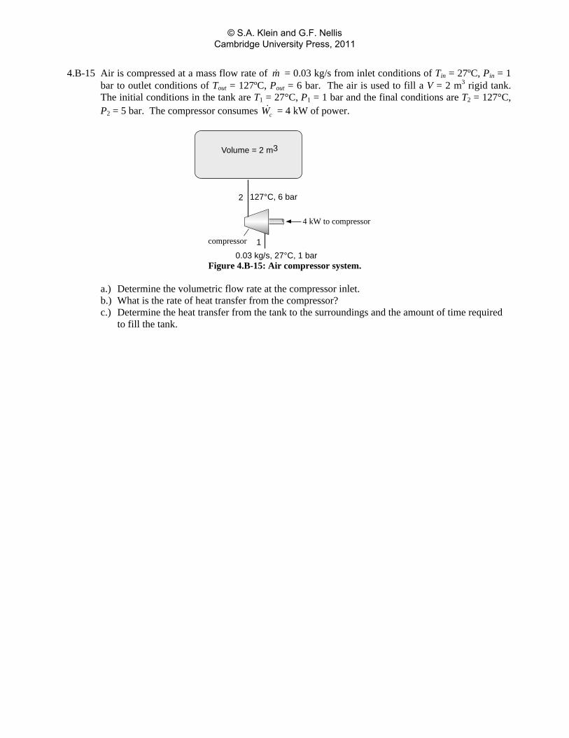
4.B-15 Air is compressed at a mass flow rate of m = 0.03 kg/s from inlet conditions of Tin = 27ºC, Pin = 1 bar to outlet conditions of Tout = 127ºC, Pout = 6 bar. The air is used to fill a V = 2 m3 rigid tank. The initial conditions in the tank are T1 = 27°C, P1 = 1 bar and the final conditions are T2 = 127°C, P2 = 5 bar. The compressor consumes cW = 4 kW of power.
4 kW to compressor
compressor
0.03 kg/s, 27°C, 1 bar1
2 127°C, 6 bar
Volume = 2 m3
Figure 4.B-15: Air compressor system.
a.) Determine the volumetric flow rate at the compressor inlet. b.) What is the rate of heat transfer from the compressor? c.) Determine the heat transfer from the tank to the surroundings and the amount of time required
to fill the tank.
© S.A. Klein and G.F. Nellis Cambridge University Press, 2011
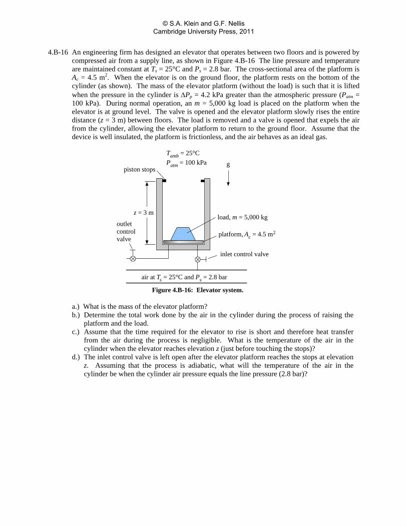
4.B-16 An engineering firm has designed an elevator that operates between two floors and is powered by compressed air from a supply line, as shown in Figure 4.B-16 The line pressure and temperature are maintained constant at Ts = 25°C and Ps = 2.8 bar. The cross-sectional area of the platform is Ac = 4.5 m2. When the elevator is on the ground floor, the platform rests on the bottom of the cylinder (as shown). The mass of the elevator platform (without the load) is such that it is lifted when the pressure in the cylinder is ΔPp = 4.2 kPa greater than the atmospheric pressure (Patm = 100 kPa). During normal operation, an m = 5,000 kg load is placed on the platform when the elevator is at ground level. The valve is opened and the elevator platform slowly rises the entire distance (z = 3 m) between floors. The load is removed and a valve is opened that expels the air from the cylinder, allowing the elevator platform to return to the ground floor. Assume that the device is well insulated, the platform is frictionless, and the air behaves as an ideal gas.
load, m = 5,000 kg
g
Tamb = 25°CPatm = 100 kPa
piston stops
z = 3 m
air at Ts = 25°C and Ps = 2.8 bar
platform, Ac = 4.5 m2
inlet control valve
outletcontrolvalve
Figure 4.B-16: Elevator system.
a.) What is the mass of the elevator platform? b.) Determine the total work done by the air in the cylinder during the process of raising the
platform and the load. c.) Assume that the time required for the elevator to rise is short and therefore heat transfer
from the air during the process is negligible. What is the temperature of the air in the cylinder when the elevator reaches elevation z (just before touching the stops)?
d.) The inlet control valve is left open after the elevator platform reaches the stops at elevation z. Assuming that the process is adiabatic, what will the temperature of the air in the cylinder be when the cylinder air pressure equals the line pressure (2.8 bar)?
© S.A. Klein and G.F. Nellis Cambridge University Press, 2011
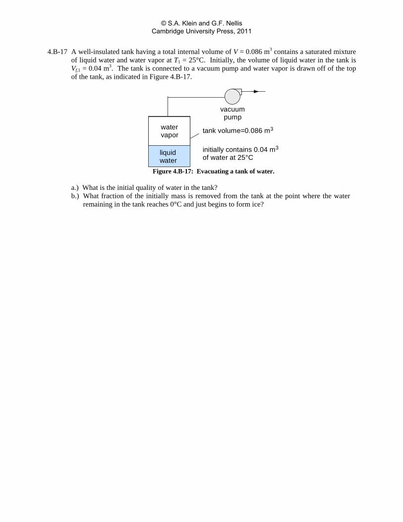
4.B-17 A well-insulated tank having a total internal volume of V = 0.086 m3 contains a saturated mixture of liquid water and water vapor at T1 = 25°C. Initially, the volume of liquid water in the tank is Vf,1 = 0.04 m3. The tank is connected to a vacuum pump and water vapor is drawn off of the top of the tank, as indicated in Figure 4.B-17.
tank volume=0.086 m3
initially contains 0.04 m3
of water at 25°Cliquidwater
watervapor
vacuumpump
Figure 4.B-17: Evacuating a tank of water.
a.) What is the initial quality of water in the tank? b.) What fraction of the initially mass is removed from the tank at the point where the water
remaining in the tank reaches 0°C and just begins to form ice?
© S.A. Klein and G.F. Nellis Cambridge University Press, 2011
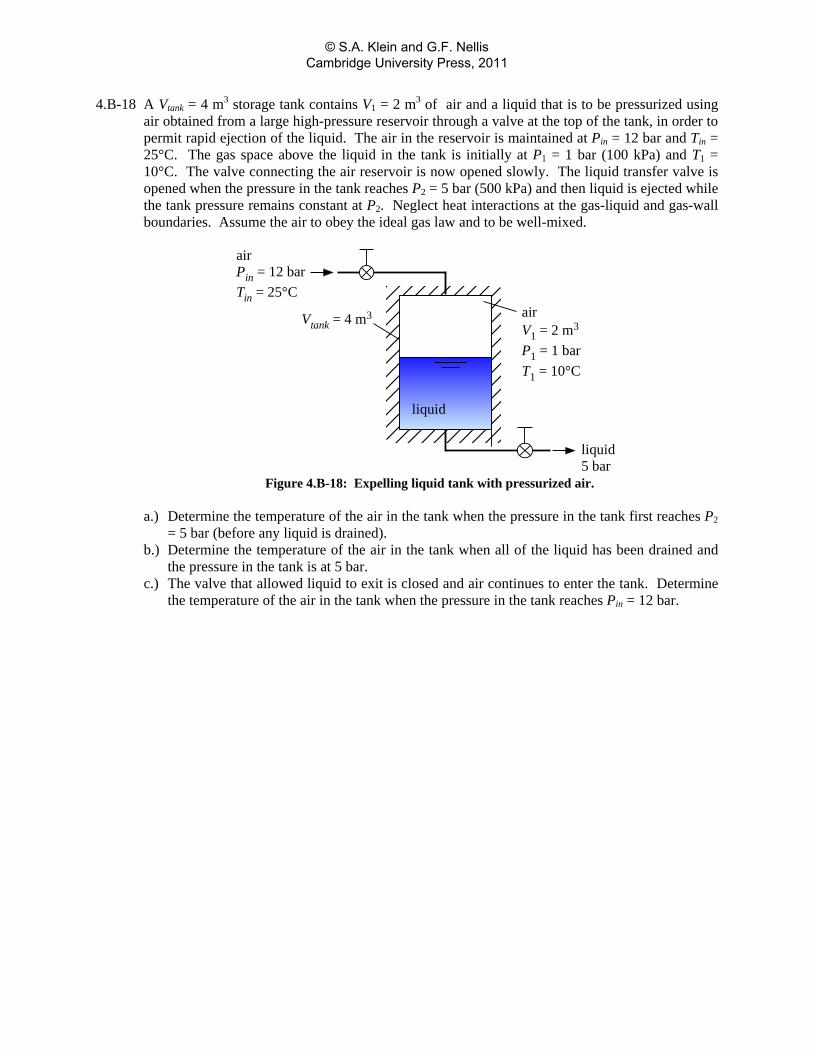
4.B-18 A Vtank = 4 m3 storage tank contains V1 = 2 m3 of air and a liquid that is to be pressurized using air obtained from a large high-pressure reservoir through a valve at the top of the tank, in order to permit rapid ejection of the liquid. The air in the reservoir is maintained at Pin = 12 bar and Tin = 25°C. The gas space above the liquid in the tank is initially at P1 = 1 bar (100 kPa) and T1 = 10°C. The valve connecting the air reservoir is now opened slowly. The liquid transfer valve is opened when the pressure in the tank reaches P2 = 5 bar (500 kPa) and then liquid is ejected while the tank pressure remains constant at P2. Neglect heat interactions at the gas-liquid and gas-wall boundaries. Assume the air to obey the ideal gas law and to be well-mixed.
airV1 = 2 m3
P1 = 1 barT1 = 10°C
liquid
airPin = 12 barTin = 25°C
liquid5 bar
Vtank = 4 m3
Figure 4.B-18: Expelling liquid tank with pressurized air.
a.) Determine the temperature of the air in the tank when the pressure in the tank first reaches P2
= 5 bar (before any liquid is drained). b.) Determine the temperature of the air in the tank when all of the liquid has been drained and
the pressure in the tank is at 5 bar. c.) The valve that allowed liquid to exit is closed and air continues to enter the tank. Determine
the temperature of the air in the tank when the pressure in the tank reaches Pin = 12 bar.
© S.A. Klein and G.F. Nellis Cambridge University Press, 2011
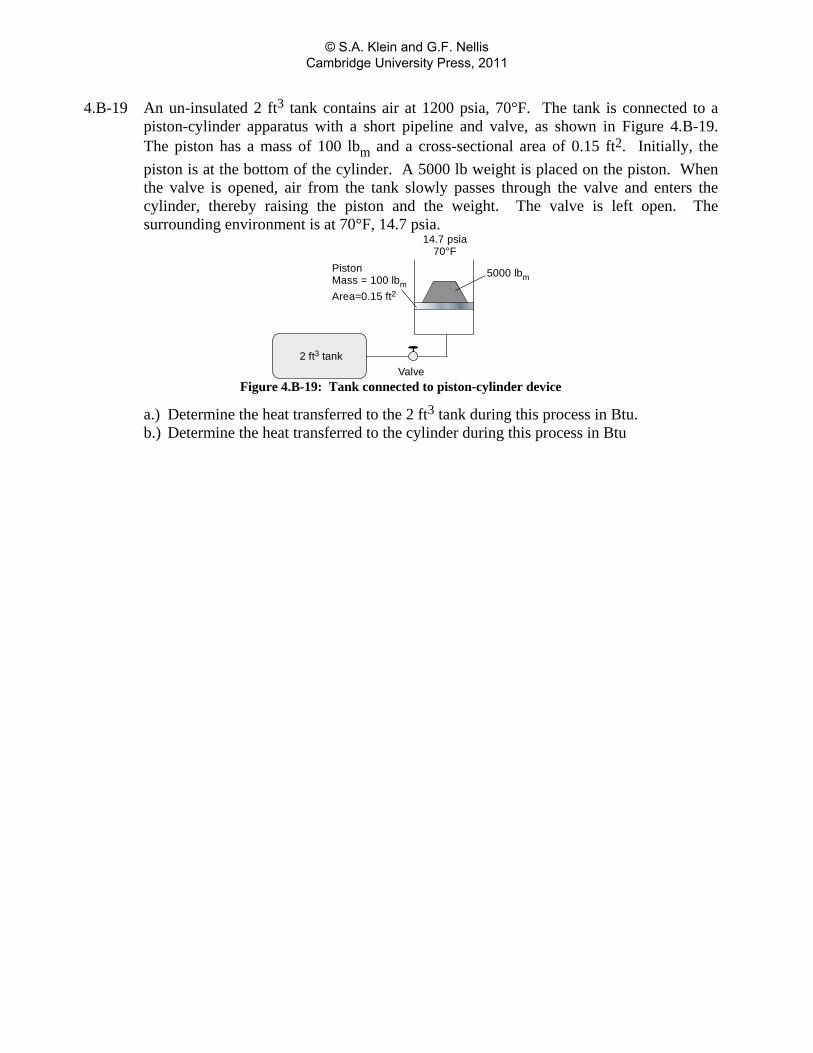
4.B-19 An un-insulated 2 ft3 tank contains air at 1200 psia, 70°F. The tank is connected to a piston-cylinder apparatus with a short pipeline and valve, as shown in Figure 4.B-19. The piston has a mass of 100 lbm and a cross-sectional area of 0.15 ft2. Initially, the piston is at the bottom of the cylinder. A 5000 lb weight is placed on the piston. When the valve is opened, air from the tank slowly passes through the valve and enters the cylinder, thereby raising the piston and the weight. The valve is left open. The surrounding environment is at 70°F, 14.7 psia.
2 ft3 tank
PistonMass = 100 lbmArea=0.15 ft2
Valve
14.7 psia70°F
5000 lbm
Figure 4.B-19: Tank connected to piston-cylinder device
a.) Determine the heat transferred to the 2 ft3 tank during this process in Btu. b.) Determine the heat transferred to the cylinder during this process in Btu
© S.A. Klein and G.F. Nellis Cambridge University Press, 2011
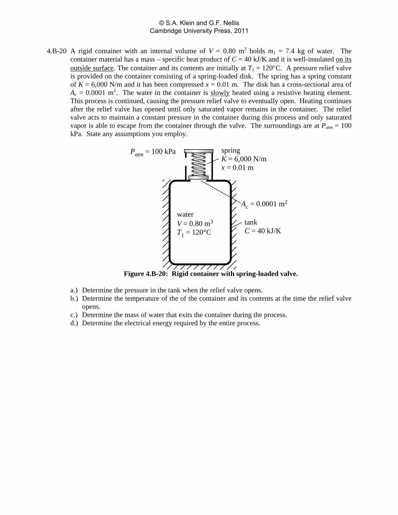
4.B-20 A rigid container with an internal volume of V = 0.80 m3 holds m1 = 7.4 kg of water. The container material has a mass – specific heat product of C = 40 kJ/K and it is well-insulated on its outside surface. The container and its contents are initially at T1 = 120°C. A pressure relief valve is provided on the container consisting of a spring-loaded disk. The spring has a spring constant of K = 6,000 N/m and it has been compressed x = 0.01 m. The disk has a cross-sectional area of Ac = 0.0001 m2. The water in the container is slowly heated using a resistive heating element. This process is continued, causing the pressure relief valve to eventually open. Heating continues after the relief valve has opened until only saturated vapor remains in the container. The relief valve acts to maintain a constant pressure in the container during this process and only saturated vapor is able to escape from the container through the valve. The surroundings are at Patm = 100 kPa. State any assumptions you employ.
Patm = 100 kPa springK = 6,000 N/mx = 0.01 m
Ac = 0.0001 m2
waterV = 0.80 m3
T1 = 120°CtankC = 40 kJ/K
Figure 4.B-20: Rigid container with spring-loaded valve.
a.) Determine the pressure in the tank when the relief valve opens. b.) Determine the temperature of the of the container and its contents at the time the relief valve
opens. c.) Determine the mass of water that exits the container during the process. d.) Determine the electrical energy required by the entire process.
© S.A. Klein and G.F. Nellis Cambridge University Press, 2011
C: Advanced Problems 4.C-1 The specific heat ratio, k = cP/cv, can be easily determined for gases that obey the ideal gas law
using the following simple experiment. A large bottle fitted with a cork stopper is filled with the gas of interest to a pressure that is slightly above atmospheric pressure. The gas is allowed to attain room temperature and the pressure in the bottle and atmospheric pressure are both carefully measured. Then the cork is removed and quickly replaced. After sufficient time has elapsed for the gas to again attain room temperature, the new pressure in the bottle is measured. a.) Show how the value of k can be determined from this experiment. Assume that cP and cv are
both constant and state any other assumptions that you employ. (Note that solution to this problem does not require the use of the Second Law of Thermodynamics.)
© S.A. Klein and G.F. Nellis Cambridge University Press, 2011
4.C-2 An understanding of the dynamic behavior of room temperature and pressure is important in the design of HVAC (Heating, Ventilating, and Air-Conditioning) equipment. Consider the following case. A W 2 = 20 m x 20 m operating room in a hospital with a ceiling height of H = 2.5 m is initially at T1 = 25°C and P1 = 100 kPa. Just before occupancy, a supply fan is turned on so that air at Pin = 110 kPa and Tin = 15°C is blown into the room at a volumetric rate of V = 2.78 m3/sec. Air within the room escapes to the adjoining hallway, which is maintained at Patm = 100 kPa. (Note that during an operation, it is important to pressurize the operating room relative to the surroundings so that bioaerosols tend to flow out of the room, reducing the possibility of infection to the patient.) Experiments have shown that the mass flow rate of air from the operating room to the hallway through cracks around the doors and other paths ( m ) can be described by a simple orifice equation of the form:
0.65m K P= Δ where K is a constant found experimentally to be 0.0157 kg/s-Pa0.65) and ΔP is the pressure difference between the room and the hallway. The lights and equipment in the room act as a Q = 3.5 kW thermal energy source. The heat transfer coefficient between the air in the room and the walls is estimated to be hconv = 15 W/m2-K. You may assume the air in the room to be fully mixed at any time and that the air obeys the ideal gas law. State and justify any other assumptions that you employ. a.) Plot the temperature and pressure of the room air as a function of time over a 5 minute period
and explain the behavior of these variables. b.) Determine the equilibrium temperature and pressure in the operating room.
© S.A. Klein and G.F. Nellis Cambridge University Press, 2011
4.C-3 The subject of the problem is a high pressure cylinder made of AISI304 stainless steel (css = 475.6 J/kg-K, ρss = 7,901 kg/m3) containing helium that is initially at T1 = 25°C and P1 = 125 bars. A safety concern has been raised that, if the gas in the cylinder were rapidly vented, the gas temperature would drop and resultant heat transfer between the gas and the cylinder could produce a hazardous situation, particularly in the neck of the bottle where the gas velocity and thus the heat transfer rate are highest. The cylinder has an internal volume of V = 0.040 m3, an internal diameter of D = 20 cm, and a wall thickness of th = 1 cm. Helium can be assumed to behave according to the ideal gas law in this problem (i.e., use 'He' and not 'Helium' in the EES property function calls). The cylinder is initially at a uniform temperature of T1 = 25°C. The helium in the cylinder can be considered to be at a uniform state at any point in time; however, its temperature and pressure vary with time. The valve throat has a diameter of Dthroat = 2 mm and choked flow is experienced in the valve throat during most of the venting process. The mass flow rate of helium through the valve during choked flow conditions is described the following equation:
112
1
kk
out throatkm A P
RT k
+−⎛ ⎞= ⎜ ⎟+⎝ ⎠
where k = cP/cv and T and P are the temperature and pressure of the helium entering the valve. The velocity at the throat is the local speed of sound. The temperature and pressure at the throat are described by the following isentropic flow equations:
2
111
2
throatT( k )T M
=−
+
( )1211
2
k / ( k )throatP k MP
− −⎛ ⎞−⎛ ⎞= +⎜ ⎟⎜ ⎟
⎝ ⎠⎝ ⎠
where M is the Mach number (which is 1 for choked flow). The helium interacts with the internal cylinder walls by convection. However, the convection coefficient is not accurately known. Estimates for this coefficient range between 10 W/m2-K < hconv < 45 W/m2-K. Calculate and plot the following quantities for a 1 minute period: a.) the temperature at the valve throat, b.) the mass flow rate of helium through the valve, c.) the bulk temperature and pressure of the helium remaining in the cylinder, and d.) the temperature of the cylinder wall, assuming it to be lumped. What is the lowest temperature of the helium occurring during this venting process? Is it important to accurately know the convection coefficient for this analysis? State any assumptions you employ in your analysis.
© S.A. Klein and G.F. Nellis Cambridge University Press, 2011
4.C-4 You may be aware of the recent interest in hydrogen as a fuel for vehicles. A concern for hydrogen vehicles is the compromise between storage tank size and vehicle range. This problem is focused on the option of compressed gas hydrogen storage. Existing designs use a tank with a carbon-fiber reinforced shell with a polymer liner. This design is relatively light and strong and it is resistant to chemicals, fatigue, creep, and permeation. In a particular case, a proposed tank has a volume of 150 liters. The tank is cylindrical with a height of 1.2 m. The design fill of these fuel tanks is 350 bar at 25C. Note that hydrogen does not obey the ideal gas law at these high pressure conditions. Filling stations can be expected to provide compressed hydrogen at 400 bar and ambient temperature. When the tank in a vehicle is filled, the temperature of the hydrogen entering the tank necessarily rises. As a result, the tank may not be completely filled when it is quickly charged to 350 bar and this situation further reduces the already limited vehicle range.
A vehicle enters a filling station with its hydrogen fuel tank at 25C and 20 bar. The tank is filled from a hydrogen supply line at 400 bar, 25C. Choked flow is experienced during the filling process in which the tank pressure is raised to 350 bar, so the filling rate obeys the following equation
1 /( 1)21
k k
d o su s
k Mm C A PR T k
where m is the hydrogen flow rate
Cd is a discharge coefficient, which is 0.60 for the supply valve, Ao is the valve throat area, which is 1.0E-6 [m2] Ps and Ts are the supply pressure and absolute temperature, respectively Ru is the universal gas constant M is the molar mass of hydrogen k is the specific heat ratio for hydrogen
The convective heat transfer coefficient between the hydrogen in the fuel tank and the
tank walls is estimated to be 45 W/m2-K. Because of the mass – specific heat product of the tank is much larger than that of the hydrogen, the temperature of the tank wall can be considered to constant during the filling process.
a.) What is the mass of hydrogen in the tank at the design fill conditions (350 bar, 25°C)?
b.) Prepare a plot of the temperature and pressure of the hydrogen in the tank as function of time for the period required to raise the pressure of the hydrogen in the tank to 350 bar. The time period should be 3 minutes or less.
c.) What is the ratio of the actual mass of hydrogen in the tank to the mass you calculated in a) when the pressure reaches 350 bar and the filling process is terminated? Is your result sensitive to the value assumed for the convective heat transfer coefficient?
d.) Estimate the driving range of the vehicle with one tank at the design fill, assuming the vehicle achieves the equivalent of 50 miles/gallon of gasoline (octane).
© S.A. Klein and G.F. Nellis Cambridge University Press, 2011
4.C-5 A vessel (20” diameter, 26-3/8” length, 2:1 ellipsoidal heads) that is filled with anhydrous ammonia vapor with an initial temperature of 500°F and 250 psig. The volume of the vessel is given by
2 3
4 2 12DV D L D
(1)
where L is the length and D is the diameter. The vessel is fitted with a pressure relief valve that has a 250 psig set pressure. ASME Boiler & Pressure Vessel Code Section VIII Division 1 (2001) allows an accumulated overpressure of 10% for determination of the relief valve capacity so that the valve actually opens when the gage pressure is 275 psi. The ammonia in the tank is now heated at a constant rate of 2500 Btu/hr. At some point the pressure reaches 275 psig and the valve opens. Assume that, after the valve opens, the pressure in the tank is constant over time at 275 psig and that the ammonia in the vessel is at a uniform state at any instant of time. You may also assume that the thermal capacity of the vessel does not contribute to this problem over the short duration under consideration. Ammonia obeys the ideal gas law at these conditions with constant specific heat values of cp = 0.695 Btu/lbm-R and cv=0.570 Btu/lbm-R
a.) Determine the initial mass of ammonia in the vessel.
b.) Determine the time required for the valve to open after the heat addition is initiated.
c.) Derive the governing mass and energy balances for the vessel as the system after the valve opens.
d.) Solve the equations developed in part c to determine the mass and temperature in the tank as a function of time for 300 s after the valve opens.
e.) Plot the total internal energy, U as a function of time. Explain the behavior you observe.
© S.A. Klein and G.F. Nellis Cambridge University Press, 2011
4.C-6 Compressed natural gas (CNG) (methane) is a logical fuel for automobiles. There is abundant supply of this fuel and it produces less carbon dioxide per unit energy than gasoline. An infrastructure for natural gas already exists and the cost is competitive with gasoline. The only problem with natural gas is that it has a low energy density, relative to gasoline, necessitating a compromise between storage tank size and vehicle range. Existing designs use three fuel cylinders, each having a diameter of 20 cm and a volume of 40 liters. The design fill of these fuel tanks is 200 bar at 25°C. The tanks are filled by connecting them to a pipeline through which methane is provided at 10°C, 270 bar. When the tanks are filled, the temperature of the gas necessarily rises. As a worst case scenario, we will assume that the fuel does not experience any heat transfer with the tank walls during the filling period (which is on the order of a few minutes.) Because the fuel is at an elevated temperature after it is charged to 200 bar, the tanks will not be completely filled when they cool to the ambient temperature and this situation can further reduce the already limited vehicle range. To avoid this situation, filling stations will need to adjust the fill pressure so that the gas tanks are charged to the design fill, i.e., the mass of fuel that exists in the tanks at 200 bar and 25°C.
a.) Develop an algorithm to determine the appropriate charging pressure for a CNG to provide the design file as a function of the initial tank pressure and temperature. Use your algorithm to prepare a plot of the required charging pressure to provide the design fill as a function of the initial tank pressure. Prepare separate plots for initial fuel temperatures of 25°C, 10°C and -5°C. Explain the behavior of these plots. Note that methane does not obey the ideal gas law at the high pressures involved in this application. Use fluid METHANE (and not CH4) in EES for property information.
b.) Estimate the driving range of a CNG vehicle with a design fill, assuming the vehicle fuel use is the equivalent of 30 miles/gallon of gasoline. The driving range is proportional to the total fuel energy. The fuel energy of methane and gasoline are 50,000 kJ/kg and 44425 kJ/kg, respectively. The density of gasoline (liquid) can be estimated using fluid n-octane in EES. State and justify any other assumptions you employ.
© S.A. Klein and G.F. Nellis Cambridge University Press, 2011
4.C-7 The USDA (in Kozempel et. al., Journal of Food Protection, Vol. 63, No. 4, 2000) has invented a new method of surface pasteurization called “flash” or “VSV” pasteurization that uses cycles of vacuum–steam–vacuum to reduce bacteria on the surface of prepared meats. A small scale experiment has been designed to test this process. The purpose of this problem is to provide an engineering analysis of this experiment. The cylindrical chamber has a diameter of D = 240 mm and a height of H = 200 mm and it is made of stainless steel. The chamber is equipped with two ball valves that connect it to a vacuum line and to a steam line. The ball valves are electronically actuated and have a rapid response time when triggered. A single hot dog (Dh = 2.5 cm in diameter and L = 13 cm length) is placed on a screen located in the center of the test chamber. At the start of the experiment, the chamber contains steam at T1 = 160°C and P1 = 1 atm. The steam is evacuated to for a period of te = 0.2 sec by opening the valve that connects the chamber to the vacuum line. The mass flow rate from the chamber ( m ) can be represented by the equation:
( 1)2( 1)2
1
kk
d ouniv
k MWm C A PR T k
+−⎡ ⎤= ⎢ ⎥+⎣ ⎦
where Cd = 0.8 is the discharge coefficient, Ao is the orifice area (the orifice diameter is Do = 1.25 cm), P and T are the pressure and temperature in the chamber, k = 1.33 is the specific heat ratio, Runiv is the universal gas constant, and MW is the molar mass of steam.
At the conclusion of the evacuation process, the valve to the vacuum line is closed and the valve
that connects the chamber to the steam line is opened. Saturated steam at Ts = 140°C is injected into the chamber in order to pasteurize the hot dog surfaces. The steam injection process is stopped when the pressure in the chamber is equal to the pressure in the steam line. The exposure times of the hot dog to the steam are deliberately short to prevent any cooking or changes in the surface properties of the product. Consequently, you may assume that heat transfer between the steam and the hot dog or the chamber surfaces is negligible during the test period. a.) Plot the pressure and temperature of the steam in the chamber as a function of time for the
evacuation process. What are the pressure and temperature at the end of the process? b.) Estimate the temperature of the steam in the chamber at the end of the steam injection process
(when the pressure in the chamber has reached the pressure of the saturated steam in the line).
© S.A. Klein and G.F. Nellis Cambridge University Press, 2011
4.C-8 A gas cylinder having a volume of 0.5 m3 contains nitrogen at 20ºC, 74 bar. The cylinder is equipped with a valve on top of the cylinder. The gas valve is opened and the nitrogen is rapidly vented to the atmosphere. During most of the venting process, the pressure in the tank is such that choked flow is occurs in the valve. As a result, the mass flow rate of nitrogen out of the tank depends only on the gas pressure and density upstream of the valve. Although nitrogen may not obey the ideal gas law at the conditions in the tank, the mass flow rate is approximately be described by the following choked flow relation when sonic conditions occur within the valve.
( 1) /( 1)21
k
wd o
kMm C A PRT k
where
Cd is a discharge coefficient which is 0.63 Ao is the orifice area. The orifice diameters is 0.025 cm P is the pressure of nitrogen in the tank g is gravitational acceleration k is the specific heat ratio which may be assumed to be 1.4 R is the universal gas constant T is the temperature of steam in the chamber Mw is the molecular molar mass of nitrogen
a.) Prepare plots of the gas pressure and temperature as a function of time for the period in which sonic flow occurs in the valve.
b.) Indicate the range of pressures on the plot for which the choked flow relation may be applicable.
c.) One would expect that if the tank were charged to a higher initial pressure, a longer time period would be required for the flow to reach the subsonic state. However, the technician who has been test-venting the tanks has indicated little relation between the initial tank pressure and the venting time. Can this be true? If so, please offer an explanation for this behavior.
© S.A. Klein and G.F. Nellis Cambridge University Press, 2011
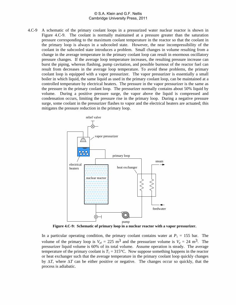
4.C-9 A schematic of the primary coolant loops in a pressurized water nuclear reactor is shown in Figure 4.C-9. The coolant is normally maintained at a pressure greater than the saturation pressure corresponding to the maximum coolant temperature in the reactor so that the coolant in the primary loop is always in a subcooled state. However, the near incompressibility of the coolant in the subcooled state introduces a problem. Small changes in volume resulting from a change in the average temperature in the primary coolant loop can result in enormous oscillatory pressure changes. If the average loop temperature increases, the resulting pressure increase can burst the piping, whereas flashing, pump cavitation, and possible burnout of the reactor fuel can result from decreases in the average loop temperature. To avoid these problems, the primary coolant loop is equipped with a vapor pressurizer. The vapor pressurizer is essentially a small boiler in which liquid, the same liquid as used in the primary coolant loop, can be maintained at a controlled temperature by electrical heaters. The pressure in the vapor pressurizer is the same as the pressure in the primary coolant loop. The pressurizer normally contains about 50% liquid by volume. During a positive pressure surge, the vapor above the liquid is compressed and condensation occurs, limiting the pressure rise in the primary loop. During a negative pressure surge, some coolant in the pressurizer flashes to vapor and the electrical heaters are actuated; this mitigates the pressure reduction in the primary loop.
electricalheaters
relief valve
vapor pressurizer
nuclear reactor
heat exchanger
steam
feedwater
pump
primary loop
Figure 4.C-9: Schematic of primary loop in a nuclear reactor with a vapor pressurizer.
In a particular operating condition, the primary coolant contains water at P1 = 155 bar. The
volume of the primary loop is Vpl = 225 m3 and the pressurizer volume is Vp = 24 m3. The pressurizer liquid volume is 60% of its total volume. Assume operation is steady. The average temperature of the primary coolant is T1 = 315°C. Now suppose something happens in the reactor or heat exchanger such that the average temperature in the primary coolant loop quickly changes by ΔT, where ΔT can be either positive or negative. The changes occur so quickly, that the process is adiabatic.
© S.A. Klein and G.F. Nellis Cambridge University Press, 2011
a.) Calculate and plot the electrical energy required and volume fraction of liquid in the vapor pressurizer for -10 K < ΔT < 0 K if the primary loop pressure is to remain constant.
b.) Calculate and plot the primary loop pressure and volume fraction of the pressurizer for 0 K < ΔT < 10 K.
c.) A relief valve is attached to the top of the vapor pressurizer in order to protect against pressure surges that are beyond the capacity of the vapor pressurizer. What is your recommendation for the pressure setting at which the relief valve should open?
© S.A. Klein and G.F. Nellis Cambridge University Press, 2011
4.C-10 A small rotary vacuum pump is used to evacuate some laboratory equipment that has an internal volume of V = 150 liters. The equipment initially contains air at P1 = 1 atm and T1 = 25°C. The pump produces a suction volumetric flow rate that is constant and equal to inV = 30 liters/min. The evacuation process would be adiabatic process except for the heat input of Q = 20 W from the motor. a.) Prepare a plot of the temperature and pressure of the air remaining inside of the equipment as
a function of time for a period of 10 minutes. Explain the behavior of the plots. b.) Determine the lowest pressure that can be attained using this vacuum pump.
© S.A. Klein and G.F. Nellis Cambridge University Press, 2011
4.C-11 SCUBA (self-contained underwater breathing apparatus) tanks must be refilled with air at 75°C to a pressure of at least 3000 psia. A large refilling station provides a compressed air line with air at 4500 psia at 75°F. A standard cylindrical tank has a volume of 28 liters with a height of 0.75 m. An empty tank typically is at 320 psia, 75°F. Experience in filling such tanks has shown resulted in the following relation between pressure and time.
1
1
1 exp 0.04794line
P P tP P
where P1 is the initial pressure in the tank, P is the pressure at time t and t is time in seconds. The tank is made of metal and the mass of metal is much greater than the mass of the air in the tank. Consequently, it is reasonable to assume that the tank wall remains at constant temperature during the filling process, which requires less than 2 minutes. However, the air temperature increases. The heat transfer coefficient between the air in the tank and the tank wall has been found to be 18.5 W/m2-K. Determine the time needed to fill the tank so that the pressure in the tank will be at least 3000 psia when the air cools to 75°F. Also, determine the pressure and temperature of the air in the tank at this time.
© S.A. Klein and G.F. Nellis Cambridge University Press, 2011
4.C-12 This problem investigates the filling process for natural gas–powered vehicles (NGV). Natural gas (methane) is currently inexpensive and widely available. Natural gas is advantageous from a global warming perspective since it results in a lower amount of carbon dioxide per equivalent mile than does gasoline. However, a concern for NGV vehicles is the compromise between storage tank size and vehicle range. Existing designs use three heavy-walled steel fuel cylinders, each having a volume of 40 liters. The tanks are cylindrical with a height of 0.65 m. The design fill of these fuel tanks is 200 bar at 20C. Additional tanks could of course be used to increase vehicle range. However, the tanks are expensive, heavy, and they reduce cargo capacity.
Filling stations ordinarily provide natural gas at 270 bar and ambient temperature. When the tanks are filled, the temperature of the gas in the vehicle storage tanks necessarily rises. As a result, the tanks may not be completely filled when they are quickly charged to 200 bar and this situation further reduces the already limited vehicle range. To avoid this situation, it will be necessary to adjust the pressure to which fuel tanks are charged, so that they are indeed full when the temperature returns to ambient.
A vehicle enters a filling station with its fuel tanks at 27C and 50 bar. The tanks are filled from a methane supply line at 270 bar, 27C. The filling rate depends on the pressure difference between the supply and fuel tank according to the following equation
.m P P 0 0075 supply tankc h
where m is the methane flow rate in kg/s, Psupply is the supply pressure in bars and Ptank is the pressure in the vehicle tank in bars. The convective heat transfer coefficient between the methane in the fuel tanks and the cylinder walls is approximately 25 W/m2-K.
Prepare plots of the pressure, temperature, and mass of methane in the vehicle storage tanks as a function of time for an eight minute filling period for these conditions. How long will it tank to fill the vehicle tanks so that the mass is equal to the design level? What are the pressure and temperature at this time? Note that methane does not obey the ideal gas law at the conditions occurring in this problem.
© S.A. Klein and G.F. Nellis Cambridge University Press, 2011
4.C-13 A well-insulated chamber having a volume of 0.028 m3 contains air that is initially at the ambient state of Tatm = 23°C and Patm = 1 atm. The chamber is connected to an air supply at Ts = 90°C and Ps = 1.34 atm. When the valve between the air supply and the chamber is opened, air flows into the chamber at a mass flow rate that is given by
in sm K P P where K is an orifice constant that has a value of 0.0001 kg/s-Pa0.5.
Simultaneously, air flows out of the chamber at rate out atmm K P P . The chamber is made of heavy metal that remains at the ambient temperature for the 30 sec duration of this experiment. The heat transfer coefficient between the flowing air and the metal is estimated to be h=10 W/m2-K. The total surface area of the chamber is A=0.55 m2. Plot the temperature and pressure of the air in the chamber for a 30 sec period and explain the observed results.
© S.A. Klein and G.F. Nellis Cambridge University Press, 2011
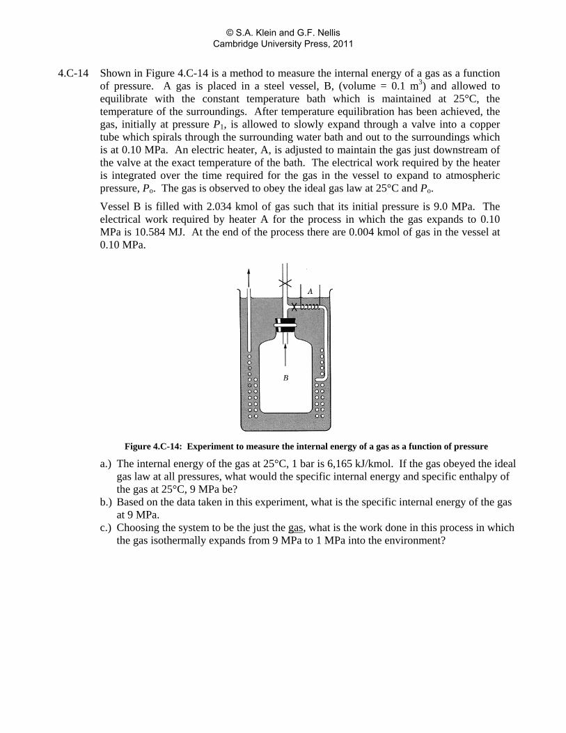
4.C-14 Shown in Figure 4.C-14 is a method to measure the internal energy of a gas as a function of pressure. A gas is placed in a steel vessel, B, (volume = 0.1 m3) and allowed to equilibrate with the constant temperature bath which is maintained at 25°C, the temperature of the surroundings. After temperature equilibration has been achieved, the gas, initially at pressure P1, is allowed to slowly expand through a valve into a copper tube which spirals through the surrounding water bath and out to the surroundings which is at 0.10 MPa. An electric heater, A, is adjusted to maintain the gas just downstream of the valve at the exact temperature of the bath. The electrical work required by the heater is integrated over the time required for the gas in the vessel to expand to atmospheric pressure, Po. The gas is observed to obey the ideal gas law at 25°C and Po.
Vessel B is filled with 2.034 kmol of gas such that its initial pressure is 9.0 MPa. The electrical work required by heater A for the process in which the gas expands to 0.10 MPa is 10.584 MJ. At the end of the process there are 0.004 kmol of gas in the vessel at 0.10 MPa.
Figure 4.C-14: Experiment to measure the internal energy of a gas as a function of pressure
a.) The internal energy of the gas at 25°C, 1 bar is 6,165 kJ/kmol. If the gas obeyed the ideal gas law at all pressures, what would the specific internal energy and specific enthalpy of the gas at 25°C, 9 MPa be?
b.) Based on the data taken in this experiment, what is the specific internal energy of the gas at 9 MPa.
c.) Choosing the system to be the just the gas, what is the work done in this process in which the gas isothermally expands from 9 MPa to 1 MPa into the environment?
© S.A. Klein and G.F. Nellis Cambridge University Press, 2011
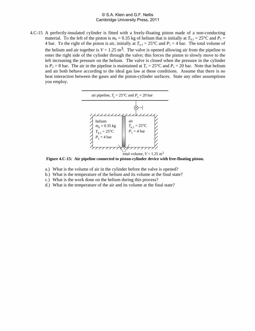
4.C-15 A perfectly-insulated cylinder is fitted with a freely-floating piston made of a non-conducting material. To the left of the piston is mh = 0.35 kg of helium that is initially at Th,1 = 25°C and P1 = 4 bar. To the right of the piston is air, initially at Ta,1 = 25°C and P1 = 4 bar. The total volume of the helium and air together is V = 1.25 m3. The valve is opened allowing air from the pipeline to enter the right side of the cylinder through the valve; this forces the piston to slowly move to the left increasing the pressure on the helium. The valve is closed when the pressure in the cylinder is P2 = 8 bar. The air in the pipeline is maintained at Ts = 25°C and Ps = 20 bar. Note that helium and air both behave according to the ideal gas law at these conditions. Assume that there is no heat interaction between the gases and the piston-cylinder surfaces. State any other assumptions you employ.
heliummh = 0.35 kgTh,1 = 25°CP1 = 4 bar
airTa,1 = 25°CP1 = 4 bar
total volume, V = 1.25 m3
air pipeline, Ts = 25°C and Ps = 20 bar
Figure 4.C-15: Air pipeline connected to piston-cylinder device with free-floating piston.
a.) What is the volume of air in the cylinder before the valve is opened? b.) What is the temperature of the helium and its volume at the final state? c.) What is the work done on the helium during this process? d.) What is the temperature of the air and its volume at the final state?
© S.A. Klein and G.F. Nellis Cambridge University Press, 2011
4.C-16 A natural gas metering system consists of a chamber having a volume of V = 4.1 liters. This chamber initially contains natural gas (assumed to pure methane) at P1 = 34 bar and the ambient temperature of Tamb = 25°C. The chamber is connected to a natural gas supply pipeline that carries natural gas at Ts = 34°C and Ps = 57 bar. The supply line has an internal diameter of Ds = 2 cm. When the ball valve between the supply line and the chamber is opened, natural gas flows into the chamber through an orifice that has a Do = 4 mm diameter. The mass flow rate entering the chamber is given by in sm K P P= − where the orifice constant has been determined to have a value of K = 0.0117 kg/s-bar0.5. Simultaneously, natural gas flows out of the chamber with mass flow rate out dm K P P= − through a Dd = 2 cm pipe containing a second orifice having the same diameter and orifice constant (Do and K). The downstream pressure is maintained at Pd = 34 bar. The chamber is made of metal that remains at the ambient temperature for the tm = 10 sec duration of this metering operation. The heat transfer coefficient between the flowing natural gas and the metal is estimated to be hconv = 26 W/m2-K. The total surface area of the chamber is As = 1.3 m2. a.) Plot the temperature and pressure of the natural gas in the chamber as a function of time.
Note any unusual or non-intuitive behavior in these plots and provide a detailed explanation.
© S.A. Klein and G.F. Nellis Cambridge University Press, 2011