Embed Size (px)
Citation preview

Chapter 4 Steady Electric Currents
Electric current, Electromotive force
Principle of current continuity, Energy dissipation.
1. Current & Current Density
2. Electromotive Force
3. Principle of Current Continuity
4. Boundary Conditions for Steady Electric Currents
5. Energy Dissipation in Steady Electric Current Fields
6. Electrostatic Simulation
1. Current & Current Density
Classification: Conduction current and convention current.
The conduction current is formed by the free electrons
(or holes) in a conductor or the ions in an electrolyte.
The convection current is resulting from the motion of the
electron, the ions, or the other charged particles in vacuum, a
solid, a liquid or a gas.
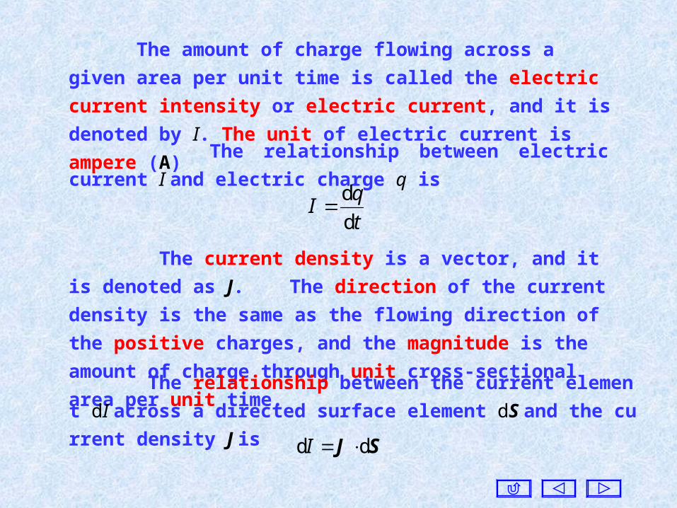
The amount of charge flowing across a given area per unit time
is called the electric current intensity or electric current, and it is
denoted by I. The unit of electric current is ampere (A)
The relationship between electric current I and electric charge
q is
t
qI
d
d
The current density is a vector, and it is denoted as J. The
direction of the current density is the same as the flowing direction
of the positive charges, and the magnitude is the amount of charge
through unit cross-sectional area per unit time.
The relationship between the current element dI across a directed
surface element dS and the current density J is
SJ dd I
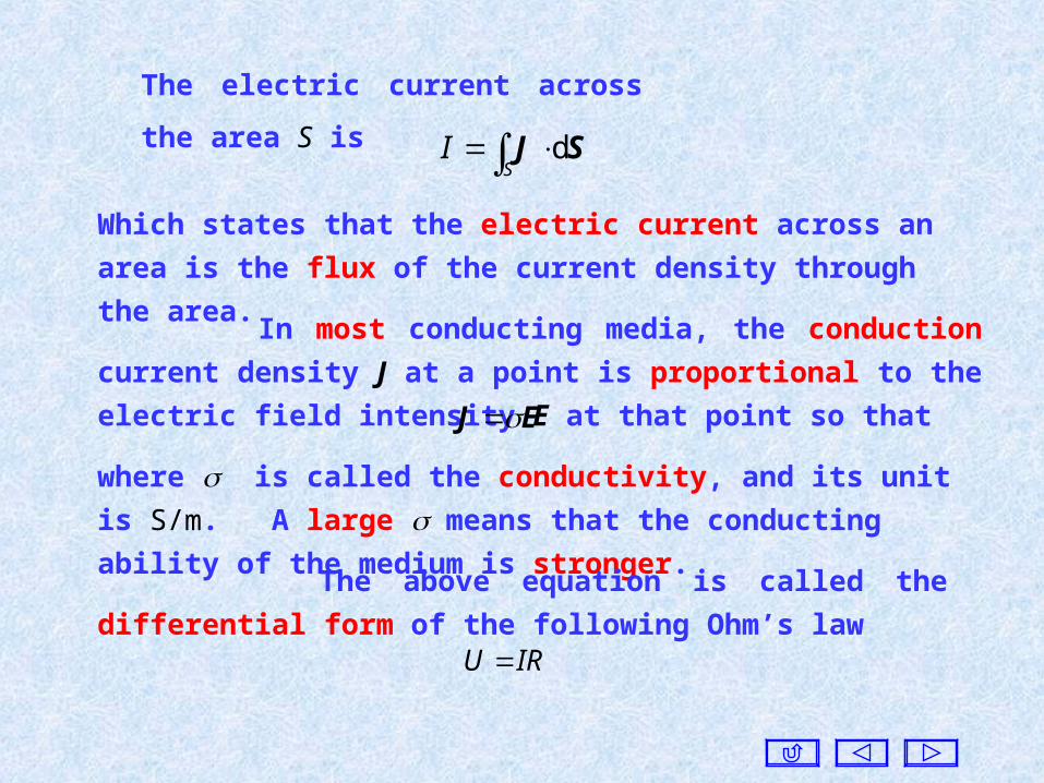
The electric current across the area S is
S
I
d SJ
Which states that the electric current across an area is the flux of the
current density through the area.
In most conducting media, the conduction current density J at a
point is proportional to the electric field intensity E at that point so
that EJ
where is called the conductivity, and its unit is S/m. A large
means that the conducting ability of the medium is stronger.
The above equation is called the differential form of the
following Ohm’s lawIRU
A conductor with infinite is called a perfect electric conductor,
or p.e.c..
A medium without any conductivity is called a perfect
dielectric or an insulator.
In a perfect electric conductor, electric current can be produced
without the influence of an electric field.
There is no steady electric field in a perfect electric conductor. Ot
herwise, an infinite current will be generated, and it results in an infi
nite energy.
In nature there exists no any p.e.c. or perfect dielectric.
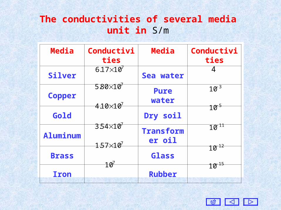
The conductivities of several mediaunit in S/m
Media Conductivities Media Conductivities
Silver Sea water
Copper Pure water
Gold Dry soil
AluminumTransformer
oil
Brass Glass
Iron Rubber
71017.6
71080.5 310
71010.4 510
71054.3 1110
71057.1 1210
710 1510
4
The magnitude of the current density of the convection current
is not proportional to the electric field intensity, and the direction
may be different from that of electric field intensity.
vJ
As the polarization of dielectrics, the conducting properties of a
medium can be homogeneous or inhomogeneous, linear or nonlinear,
and isotropic or anisotropic, with same meanings as before.
If the charge density is , and the moving velocity is v, and then
The above equations are valid only for a linear isotropic medium.
EConducting medium
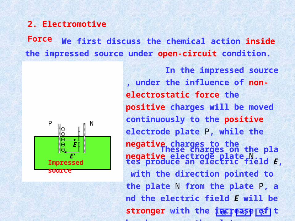
2. Electromotive Force
We first discuss the chemical action inside the impressed source
under open-circuit condition.
In the impressed source , under the
influence of non-electrostatic force the
positive charges will be moved continuously
to the positive electrode plate P, while the
negative charges to the negative electrode
plate N.
These charges on the plates produce an
electric field E, with the direction pointed t
o the plate N from the plate P, and the elect
ric field E will be stronger with the increase
of the charges on the plates.
P N
E
Impressed sourceE'
The electric force caused by the charges on the plates will resist
the movement of the charges in the source. When the electric force
is equal to the non-electrostatic force, the charges are stopped, and
the charges on the plates will be constant.
This impressed electric field intensity is still defined as the
force acting on unit positive charge, but it is denoted as E'.
Since the non-electrostatic force behaves as the force acting
on the charge, the non-electrostatic force is usually considered a
s that produced by an impressed electric field.
The impressed electric field E' pushes the positive charges to the
positive electrode plate, and the negative charges to the negative
electrode plate, and the direction of is opposite to that of the
electric field E produced by the charges on the plates.
If the conducting medium is connected, the positive charges on
the positive electric plate will be moved to the negative electric plate
through the conducting medium, while the negative charges on the
negative electric plate to the positive electric plate. In this way, the
charges on the plates will be decreased, and E < E' . The charges in
the source will be moved again.
when the impressed electric field is equal but opposite to the ele
ctric field produced by the charges on the plates, and the charges wi
ll be at rest.
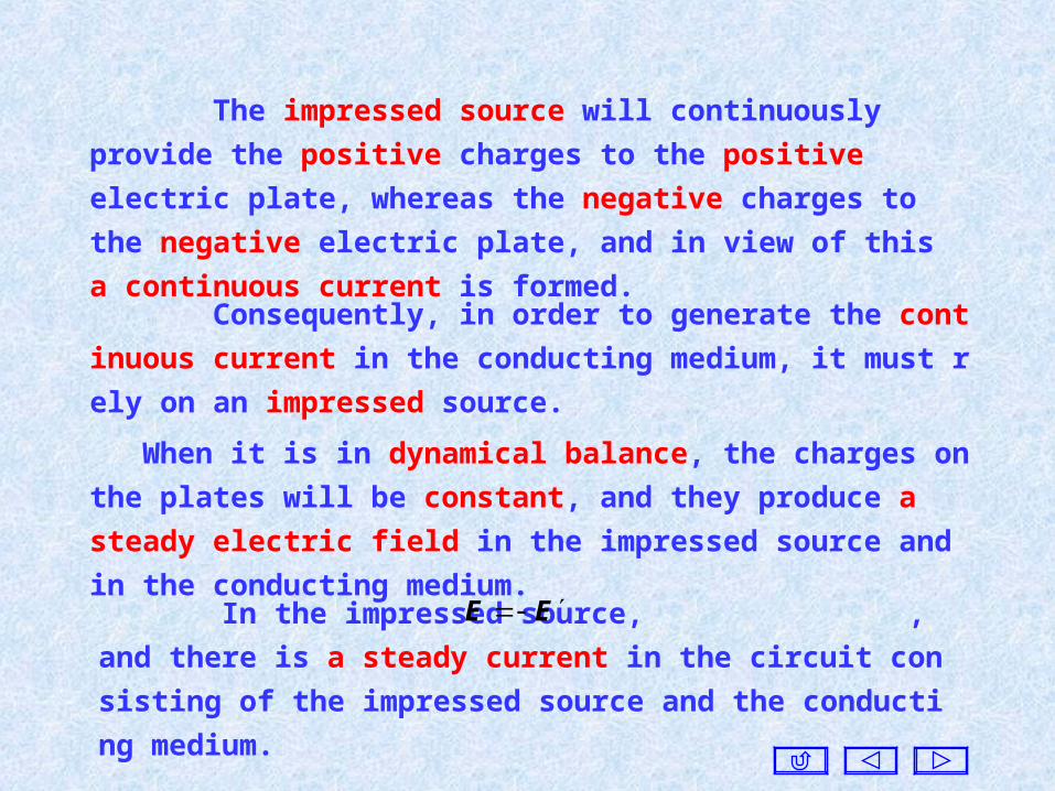
The impressed source will continuously provide the positive
charges to the positive electric plate, whereas the negative charges to
the negative electric plate, and in view of this a continuous current is
formed.
When it is in dynamical balance, the charges on the plates will be
constant, and they produce a steady electric field in the impressed
source and in the conducting medium.
In the impressed source, , and there is a steady current
in the circuit consisting of the impressed source and the conducting
medium.
EE
Consequently, in order to generate the continuous current in the c
onducting medium, it must rely on an impressed source.
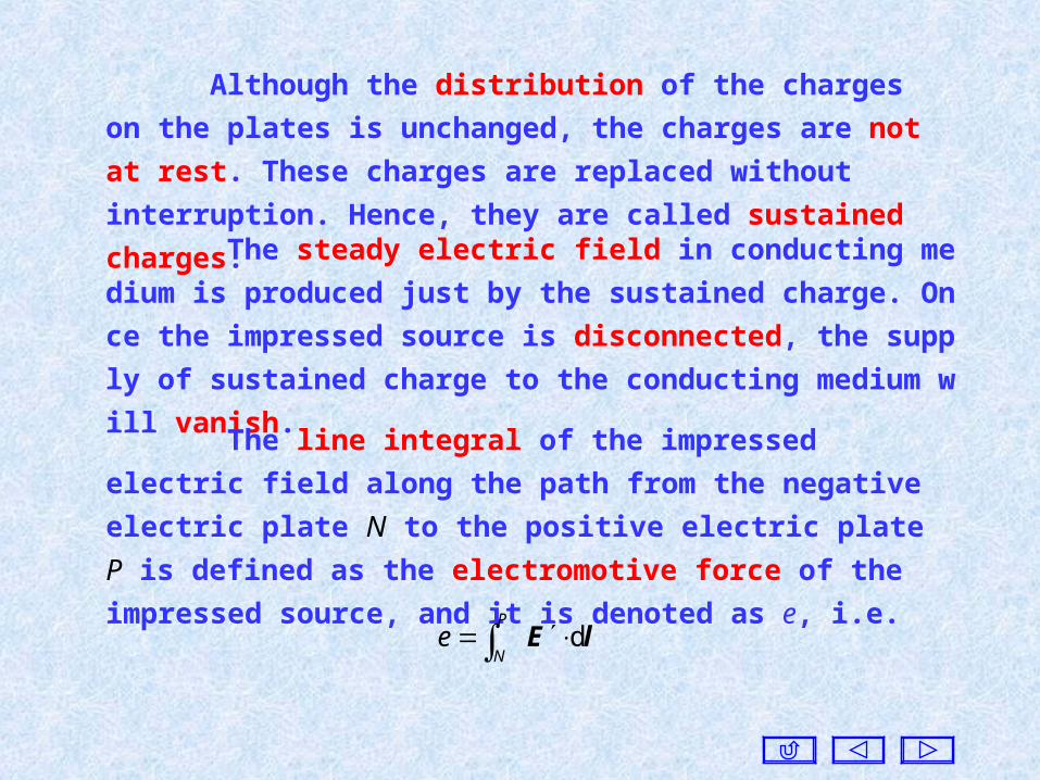
Although the distribution of the charges on the plates is
unchanged, the charges are not at rest. These charges are replaced
without interruption. Hence, they are called sustained charges.
The steady electric field in conducting medium is produced just
by the sustained charge. Once the impressed source is disconnected, t
he supply of sustained charge to the conducting medium will vanish.
The line integral of the impressed electric field along the path
from the negative electric plate N to the positive electric plate P is
defined as the electromotive force of the impressed source, and it is
denoted as e, i.e.
lE d
P
Ne

When it is in dynamical balance, in the impressed
source. Therefore, the above equation can be rewritten as
EE
lE d
P
Ne
The steady electrode field caused by the sustained charges on the
plates is also a conservative field, and the line integral of it around a
closed circuit should be zero, i.e.
l
0d lE
For homogeneous media, the above equation becomes
l
0d lJ
Consider that in the conducting medium, , we haveEJ
l
0d lJ
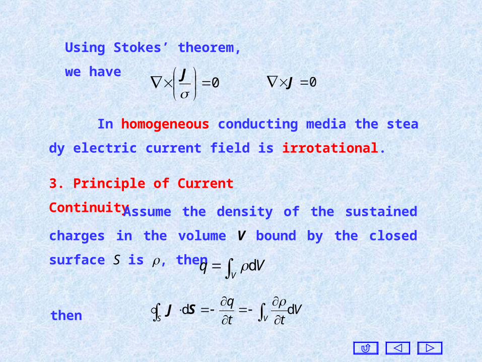
Using Stokes’ theorem, we have
0
J
0 J
In homogeneous conducting media the steady electric current
field is irrotational.
3. Principle of Current Continuity
Assume the density of the sustained charges in the volume V
bound by the closed surface S is , then
V
Vq
d
Vtt
qS V
dd
SJthen
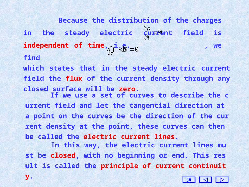
Because the distribution of the charges in the steady electric
current field is independent of time, i.e. , we find0
t
S
0d SJ
which states that in the steady electric current field the flux of the
current density through any closed surface will be zero.
In this way, the electric current lines must be closed, with no be
ginning or end. This result is called the principle of current continu
ity.
If we use a set of curves to describe the current field and let the ta
ngential direction at a point on the curves be the direction of the curr
ent density at the point, these curves can then be called the electric cu
rrent lines.
By using the divergence theorem, we obtain
t
J
which is called the charge conservation principle in differential
form. Hence, for a steady electric current field, we have
0 J
which states that the steady electric current field is solenoidal.
4. Boundary Conditions for Steady Electric Currents
The integral forms of the equations for steady electric current
field are as follows:
l
0d lJ
S
0d SJ
0
J
0 J
And the corresponding differential forms are
From the equations in integral form we can find the boundary
condition for the tangential components of the current densities to
be
2
t2
1
t1
JJ
And the normal components are 2n1n JJ
The tangential components of the current densities are
discontinuous, while the normal components are continuous.
Since , we find the boundary conditions for the
steady electric field can be obtained as follows:
EJ
n221n1
2tt1
EE
EE
2
t2
1
t1
JJ
2n1n JJ
Since there is no the electric field cannot in a perfect electric
conductor, the tangential components of a steady electric current
cannot exist on the surface.
Therefore, when an electric current flows into or out of a perfect
electric conductor, the electric current lines are always perpendicular
to the surface.
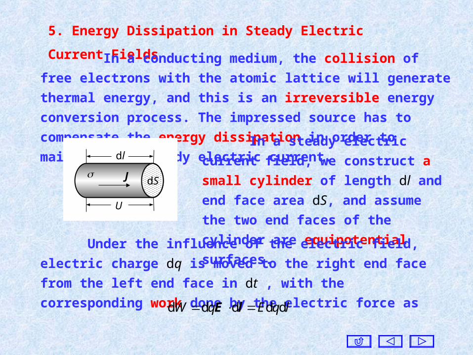
5. Energy Dissipation in Steady Electric Current Fields
In a conducting medium, the collision of free electrons with the
atomic lattice will generate thermal energy, and this is an irreversible
energy conversion process. The impressed source has to compensate the
energy dissipation in order to maintain the steady electric current.
In a steady electric current field, we
construct a small cylinder of length dl and
end face area dS, and assume the two end
faces of the cylinder are equipotential
surfaces.
dl
U
J dS
Under the influence of the electric field, electric charge dq is moved
to the right end face from the left end face in dt , with the corresponding
work done by the electric force as
lqEqW ddddd lE
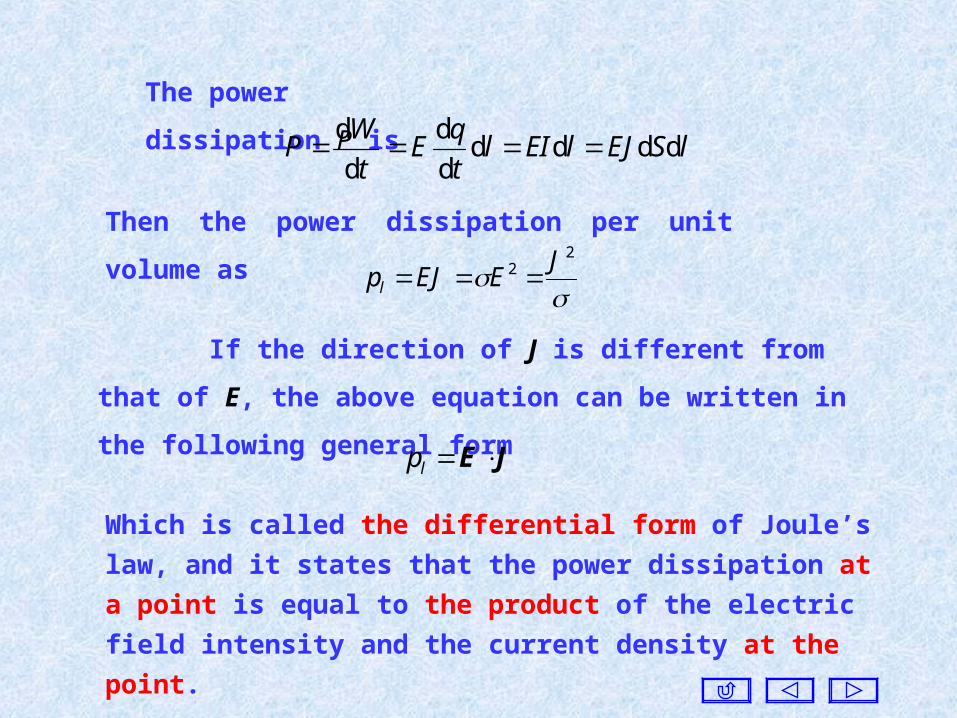
The power dissipation P is
lSEJlEIlt
qE
t
WP dddd
d
d
d
d
Then the power dissipation per unit volume as
22 J
EEJpl
If the direction of J is different from that of E, the above equation
can be written in the following general form
JE lp
Which is called the differential form of Joule’s law, and it states that
the power dissipation at a point is equal to the product of the
electric field intensity and the current density at the point.
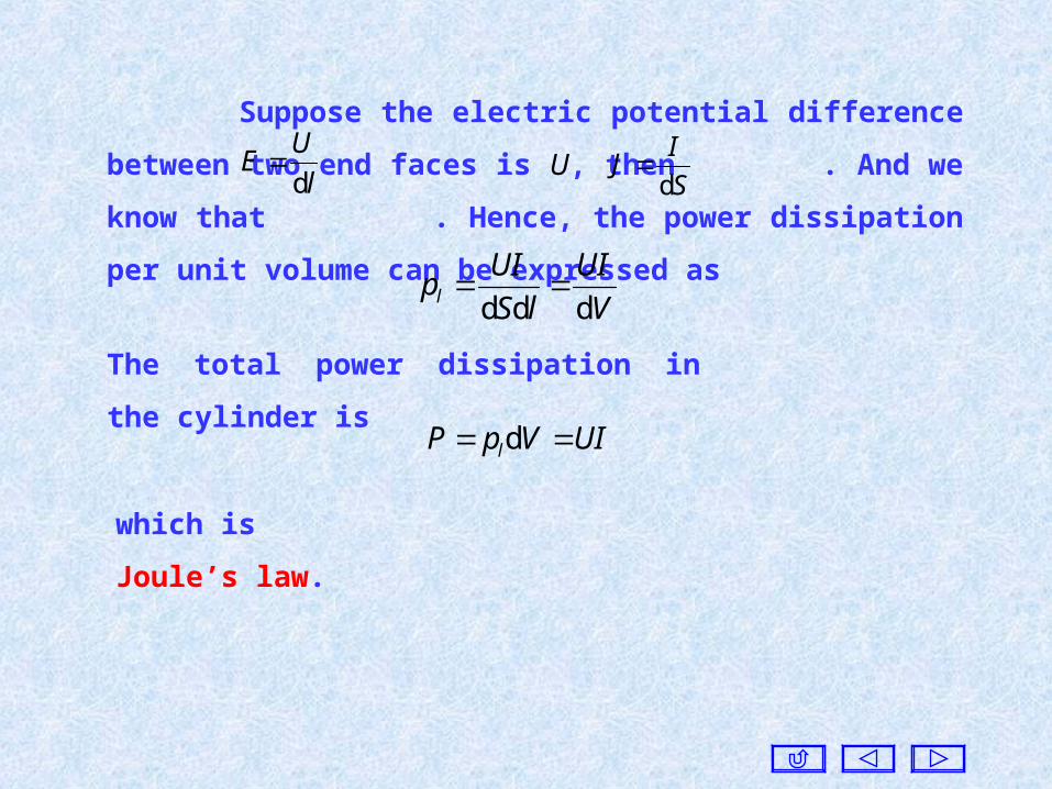
Suppose the electric potential difference between two end faces
is U, then . And we know that . Hence, the power
dissipation per unit volume can be expressed asl
UE
d
S
IJ
d
V
UI
lS
UIpl ddd
The total power dissipation in the cylinder is
UIVpP l d
which is Joule’s law.
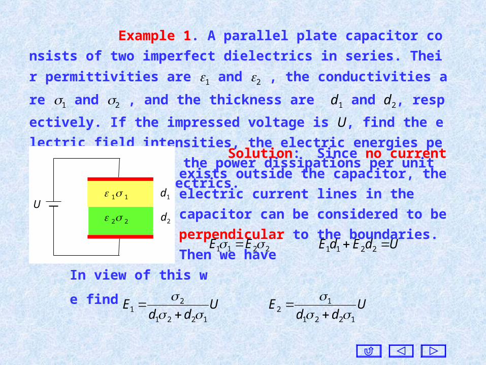
Example 1. A parallel plate capacitor consists of two imperfect die
lectrics in series. Their permittivities are 1 and 2 , the conductivities are
1 and 2 , and the thickness are d1 and d2, respectively. If the impressed
voltage is U, find the electric field intensities, the electric energies per un
it volume, and the power dissipations per unit volume in two dielectrics.
Solution: Since no current exists outside the
capacitor, the electric current lines in the
capacitor can be considered to be perpendicular
to the boundaries. Then we have
2211 EE UdEdE 2211
In view of this we find
Udd
E1221
21
Udd
E1221
12
1 1
2 2
d1
d2
U
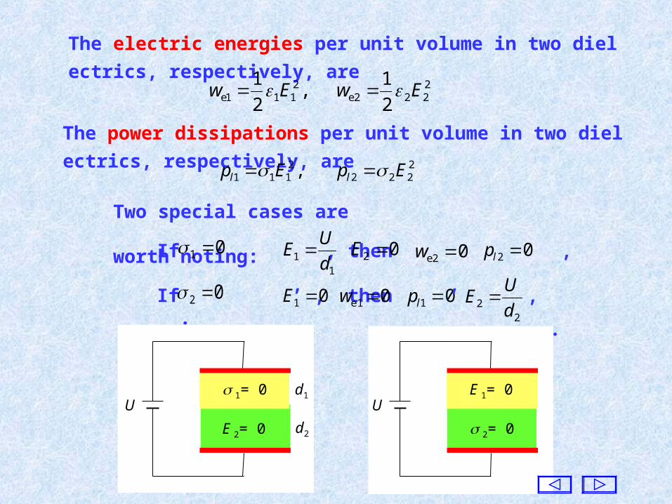
The electric energies per unit volume in two dielectrics, respectively,
are 2222e
2111e 2
1 ,
2
1EwEw
The power dissipations per unit volume in two dielectrics, respectively,
are 2222
2111 , EpEp ll
Two special cases are worth noting:
If , then , , , .02 01 E 0e1 w 01 lp2
2 d
UE
If , then , , , .01 1
1 d
UE 02 E 02e w 02 lp
d1
d2
1= 0
E 2= 0
UE 1= 0
2= 0
U
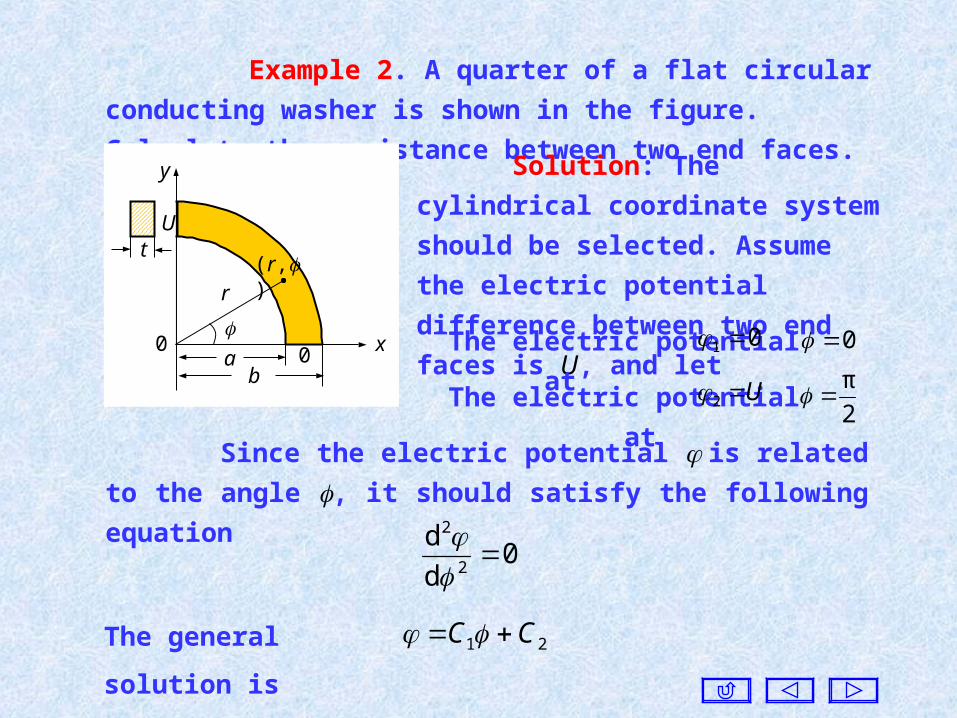
Example 2. A quarter of a flat circular conducting washer is
shown in the figure. Calculate the resistance between two end faces.
U
y
x
t
ab
r
0
(r,)
0
Solution: The cylindrical coordinate
system should be selected. Assume the
electric potential difference between two
end faces is U, and let
Since the electric potential is related to the angle , it should
satisfy the following equation
0d
d2
2
The general solution is 21 CC
The electric potential at 01 0
The electric potential atU22
π

Based on the given boundary conditions, we find
π
2U
r
U
r π
2 eeEJ
The current density J in the conducting medium is
Then the current I flowing into the conducting medium across the
end face at is2
π
)d (π
2d rt
r
UI
SS
eeSJ
a
bUt
r
rUt b
aln
π
2d
π
2
Consequently, the resistance R between two end faces is
ab
tI
UR
ln 2
π
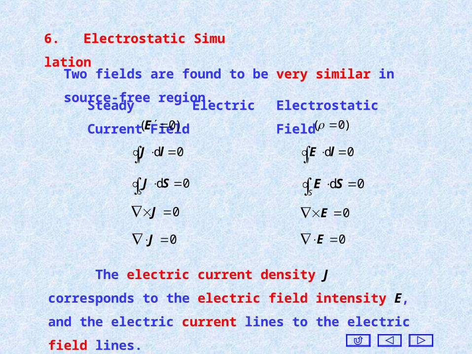
6. Electrostatic Simulation
Two fields are found to be very similar in source-free region.
Steady Electric Current Field
)0( E
Electrostatic Field
)0(
0d
llJ 0d
l
lE
0d
SSJ 0d
S
SE
0 J 0 E
0 J 0 E
The electric current density J corresponds to the electric field
intensity E, and the electric current lines to the electric field lines.
If the steady electric current field has the same boundary
conditions as that for the electrostatic field, the distribution of
the current density will be the same as that of the electric field
intensity.
In some cases, since the steady electric current field is easy
to be constructed and measured, the electrostatic field can be
investigated based on the steady electric current field with the
same boundary conditions, and this method is called electrostatic
simulation.
Based on this similarity, the solution of the steady electric
current field can be found directly from the results of the
electrostatic field.
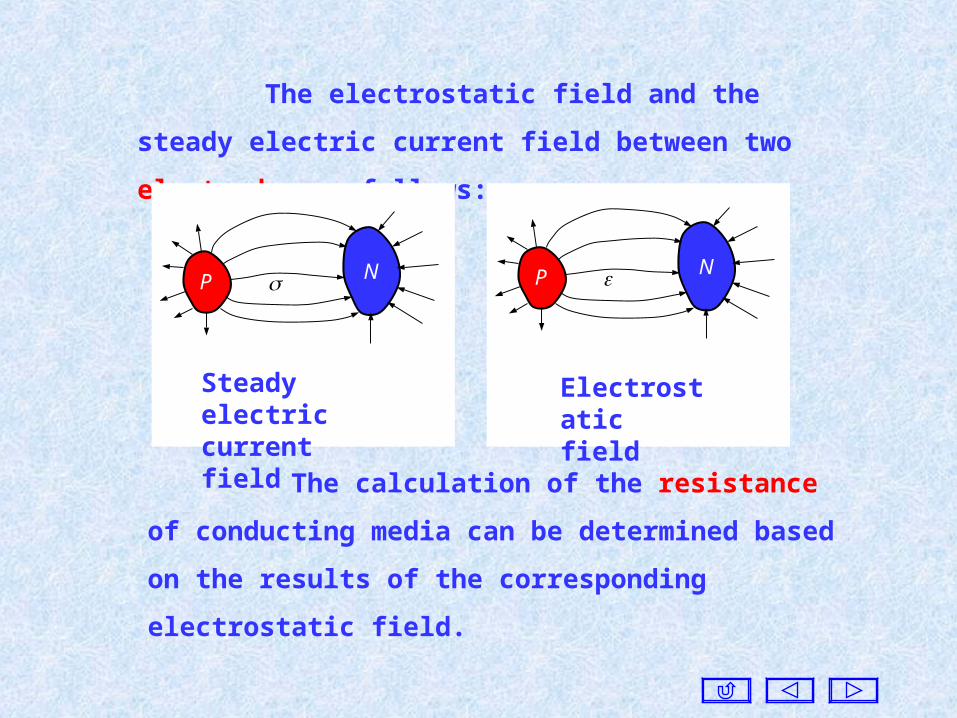
The electrostatic field and the steady electric current
field between two electrodes as follows:
P N
Steady electric current field
P N
Electrostatic field
The calculation of the resistance of conducting media
can be determined based on the results of the corresponding
electrostatic field.
CR CG
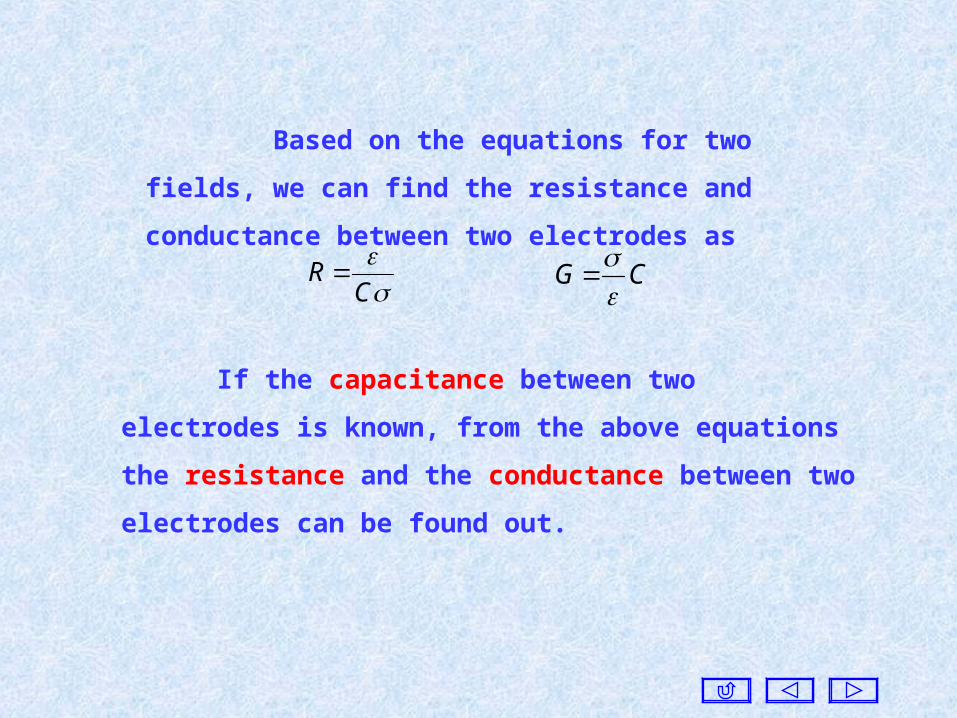
Based on the equations for two fields, we can find the
resistance and conductance between two electrodes as
If the capacitance between two electrodes is known, from the
above equations the resistance and the conductance between two
electrodes can be found out.

The capacitance of a coaxial line per unit length is ,
where b is the inner radius of the outer conductor, and a is the
radius of the internal conductor. If the conductivity of the filled
dielectric is , the leakage conductance per unit length G1 is
)/ln(
π21 ab
C
)/ln(
π21 ab
G
d
S
d
SG
The capacitance of a parallel plate capacitor of plate area S and
separation d is . If the conductivity of the imperfect dielectric
is , the leakage conductance G between two electric plates of the
parallel plate capacitor is
d
SC
CR CG