Embed Size (px)
Citation preview

Electric potential difference
Electromotive force- emf
Circuits
Conductors and resistors
Resistivity and Resistance
Circuit Diagrams
Electric Current & DC Circuits
Measurement
Electric Circuits

1. Electric Potential Difference
BABAAB mghmghW GPEGPE
1). Electric Potential Energy
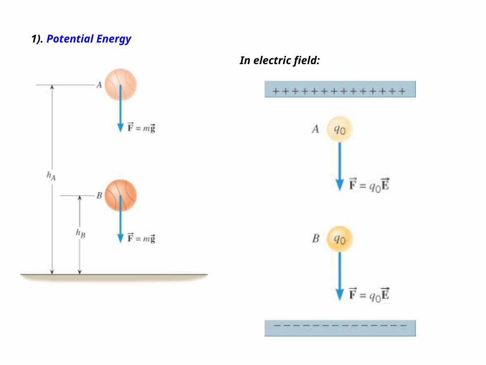
1). Potential Energy
In electric field:

1). electric Potential Energy
BAABW EPEEPE
When E is uniform:
)(0 BAAB ddEqW

o
B
o
A
o
AB
qqq
W EPEEPE
The potential energy per unit chargeis called the electric potential.And :
BAo
B
o
A
o
AB VVqqq
W
EPEEPE
Electric Potential Difference is:
BABA EdEd
q
ddEqV
0
0 ))((
SI Unit of Electric Potential: joule/coulomb = volt (V)
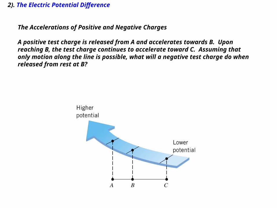
2). The Electric Potential Difference
The Accelerations of Positive and Negative Charges
A positive test charge is released from A and accelerates towards B. Uponreaching B, the test charge continues to accelerate toward C. Assuming thatonly motion along the line is possible, what will a negative test charge do whenreleased from rest at B?
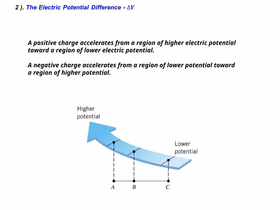
A positive charge accelerates from a region of higher electric potentialtoward a region of lower electric potential.
A negative charge accelerates from a region of lower potential towarda region of higher potential.
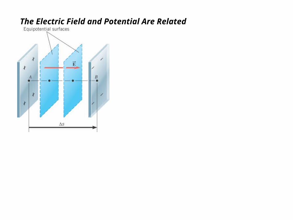
The Electric Field and Potential Are Related
2. Electromotive Force – emf
emf – is the voltage developed by any source of electrical energy such as a battery or dynamo. It is generally defined as the potential for a source in a circuit.
measured in volts

2. Electromotive Force from Electric battery- Voltage
The symbol for a battery in a circuit diagram. It originated as a schematic drawing of the earliest type of battery, a voltaic pile.
Various cells and batteries (top-left to bottom-right): two AA, one D, one handheld ham radiobattery, two 9-volt (PP3), two AAA, one C, onecamcorder battery, one cordless phone battery.
Line art drawing of a dry cell:1. brass cap, 2. plastic seal, 3. expansion space, 4. porous cardboard, 5. zinc can, 6. carbon rod, 7. chemical mixture.
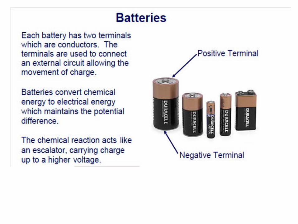

Within the electrochemical cells of the battery, there is an electric field established between the two terminals, directed from the positive terminal towards the negative terminal. The negative terminal is described as the low potential terminal.
The SI unit on electric potential difference is the volt, V (in honor of Alessandro Volta).
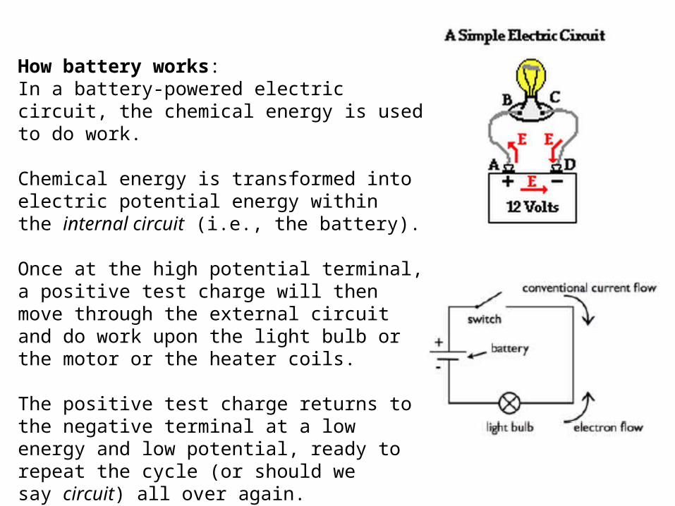
How battery works:In a battery-powered electric circuit, the chemical energy is used to do work.
Chemical energy is transformed into electric potential energy within the internal circuit (i.e., the battery).
Once at the high potential terminal, a positive test charge will then move through the external circuit and do work upon the light bulb or the motor or the heater coils.
The positive test charge returns to the negative terminal at a low energy and low potential, ready to repeat the cycle (or should we say circuit) all over again.
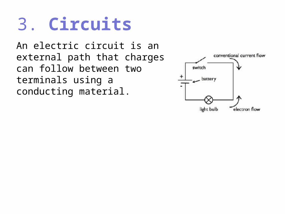
3. CircuitsAn electric circuit is an external path that charges can follow between two terminals using a conducting material.

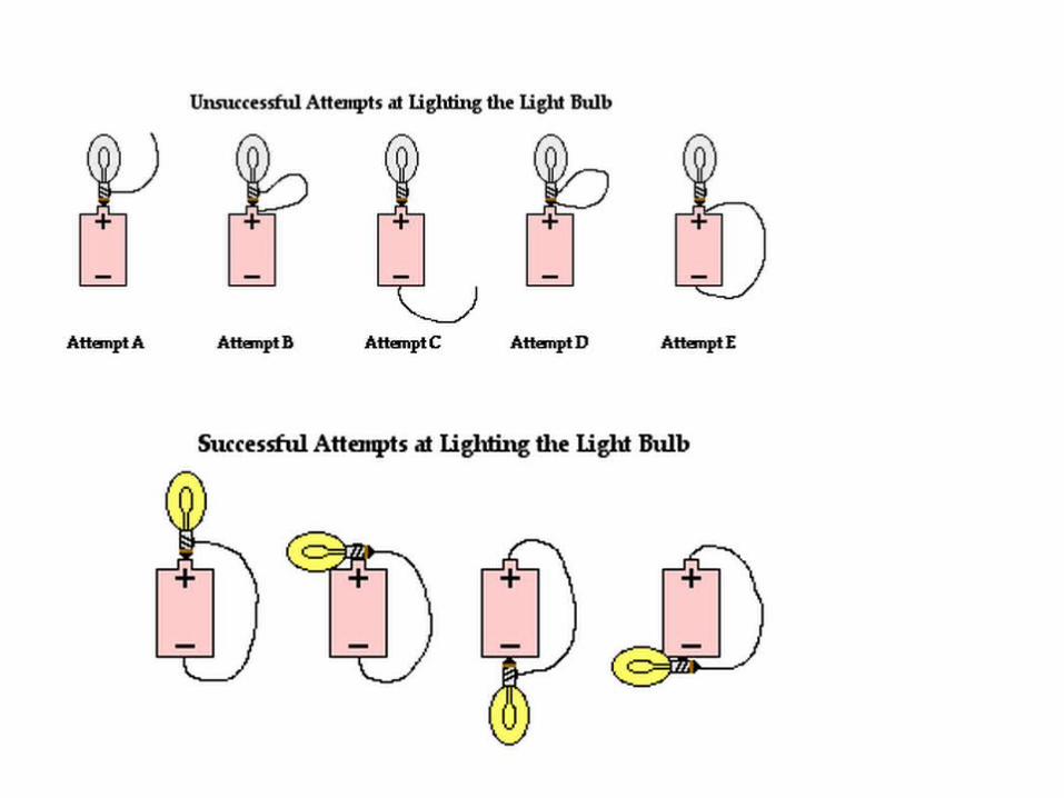
1). Requirements •the path must be complete and unbroken--There must be a closed conducting loop in the external circuit that stretches from the high potential, positive terminal to the low potential, negative terminal.
•The Requirement of an Energy Supply--There must be an energy supply capable doing work on charge to move it from a low energy location to a high energy location and thus establish an electric potential difference across the two ends of the external circuit.
Electromotive Force and Current
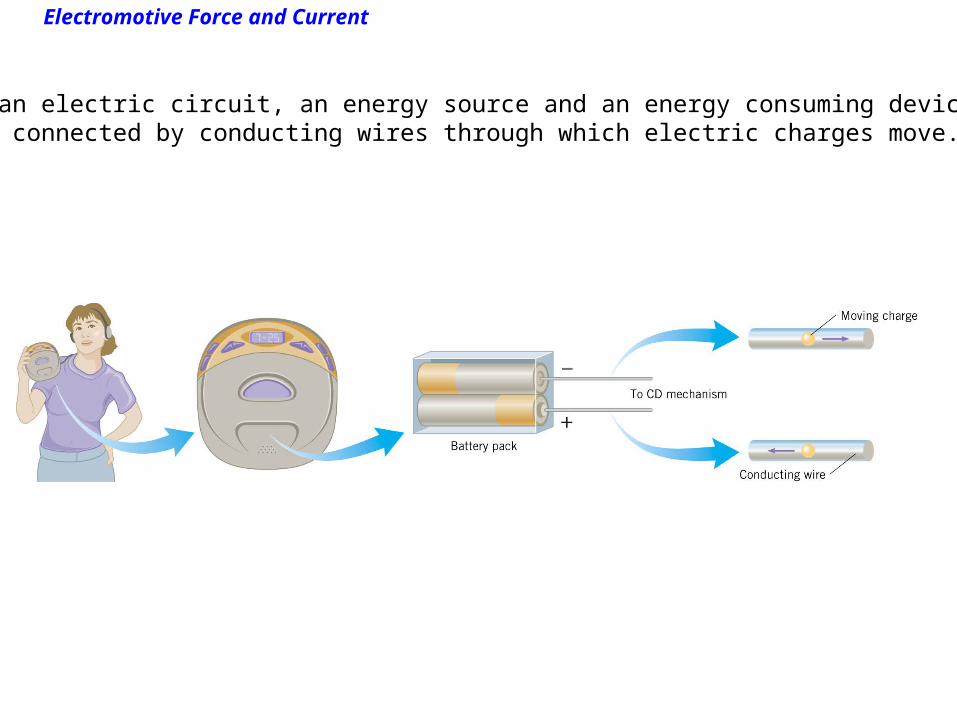
In an electric circuit, an energy source and an energy consuming deviceare connected by conducting wires through which electric charges move.
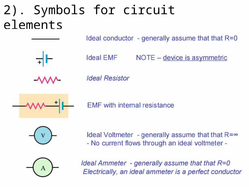
2). Symbols for circuit elements
A Ideal conductor - generally assume that that R=0 Ideal EMF NOTE – device is asymmetric Ideal Resistor EMF with internal resistance Ideal Voltmeter - generally assume that that R=∞ - No current flows through an ideal voltmeter – Ideal Ammeter - generally assume that that R=0 Electrically, an ideal ammeter is a perfect conductor
Electromotive Force and Current
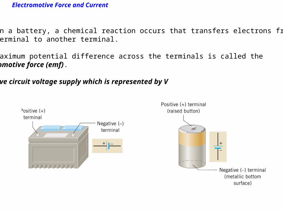
Within a battery, a chemical reaction occurs that transfers electrons fromone terminal to another terminal.
The maximum potential difference across the terminals is called the electromotive force (emf).
emf give circuit voltage supply which is represented by V
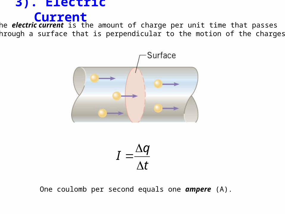
3). Electric CurrentThe electric current is the amount of charge per unit time that passesthrough a surface that is perpendicular to the motion of the charges.
t
qI
One coulomb per second equals one ampere (A).

Current, resistance and electromotive force
Current is a concept with wide spread applications describing the rate of flow of some quantity that can be:
-Throughput of cars per time interval:
-water volume coming out of a hose per time interval:

20.1 Electromotive Force and Current
If the charges move around the circuit in the same direction at all times,the current is said to be direct current (dc).
If the charges move first one way and then the opposite way, the current is said to be alternating current (ac).
20.1 Electromotive Force and Current
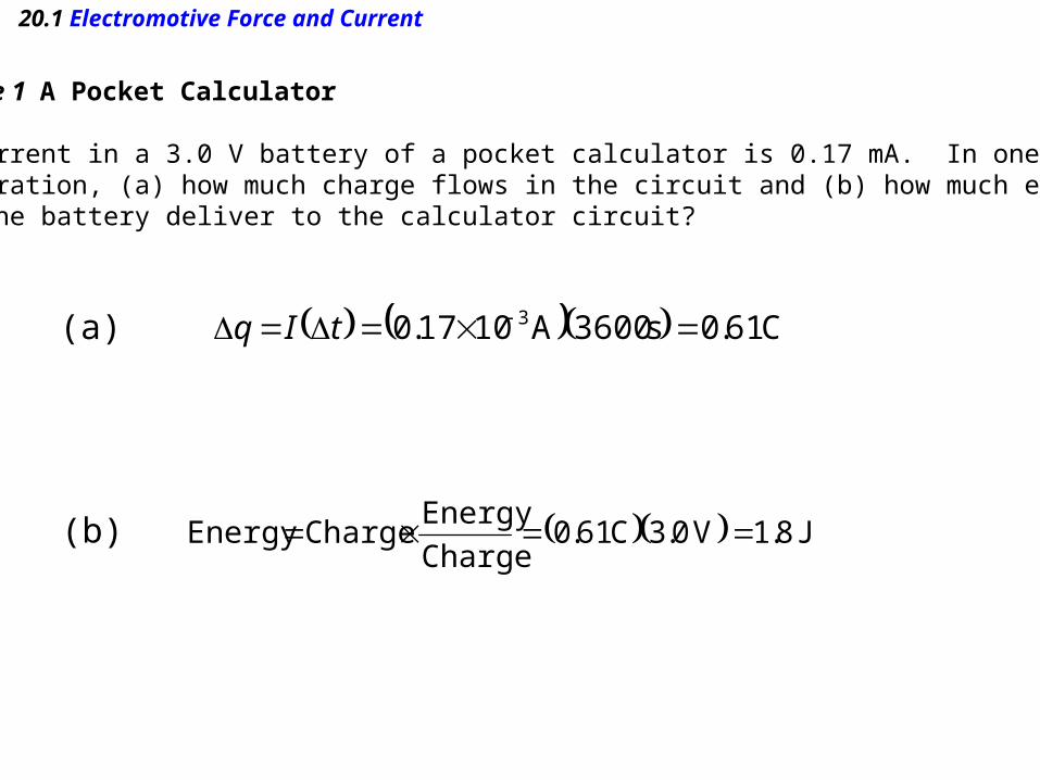
Example 1 A Pocket Calculator
The current in a 3.0 V battery of a pocket calculator is 0.17 mA. In one hourof operation, (a) how much charge flows in the circuit and (b) how much energydoes the battery deliver to the calculator circuit?
(a)
(b)
C 61.0s 3600A1017.0 3 tIq
J 8.1V 0.3C 61.0Charge
Energy Charge Energy
20.1 Electromotive Force and Current
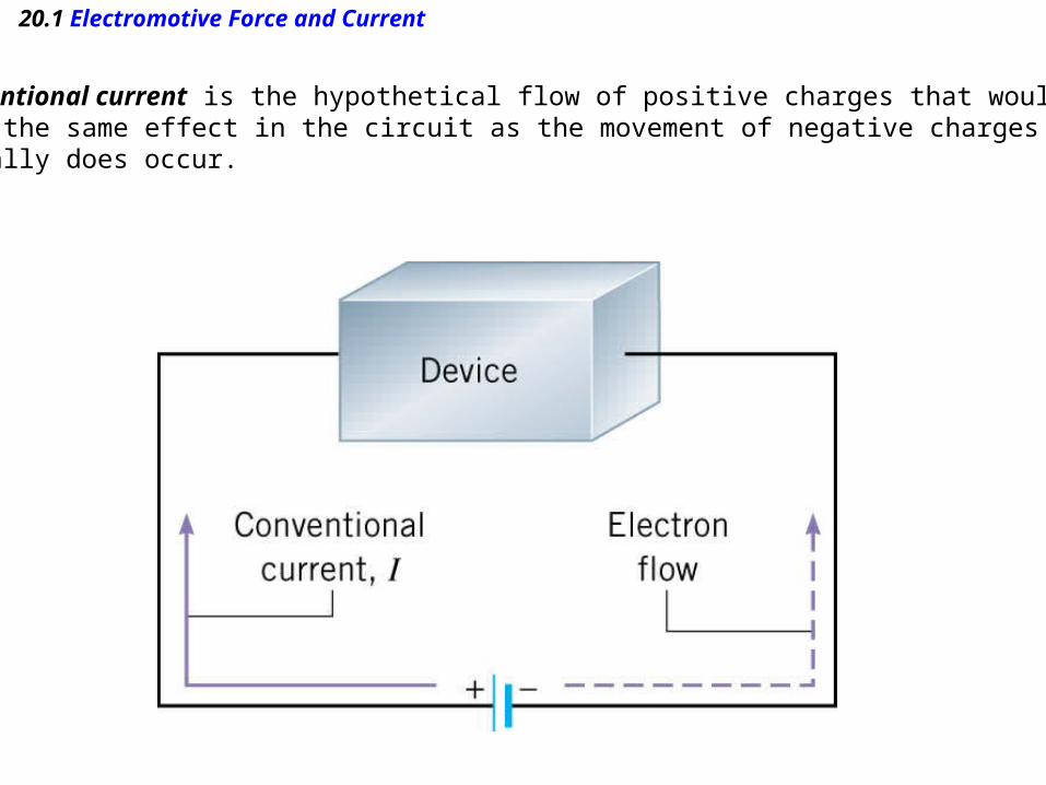
Conventional current is the hypothetical flow of positive charges that wouldhave the same effect in the circuit as the movement of negative charges thatactually does occur.

Electron's journey through a circuit
In the wires of electric circuits, an electron is the actual charge carrier.
zigzag path that results from countless collisions with the atoms of the conducting wire

Conductor’s Resistance
Some conductors "conduct" better or worse than others. Reminder:conducting means a material allows for the free flow of electrons.
The flow of electrons is just another name for current.
Another way to look at it is that some conductors resist current to a greater or lesser extent.
We call this resistance, R. Resistance is measured in ohms which is noted by the Greek symbol omega (Ω)

Demohttp://phet.colorado.edu/en/simulations/category/physics/electricity-magnets-and-circuits
Battery - resistor circuit
Circuit Construction Kit (DC Only)
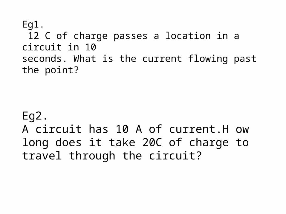
Eg1. 12 C of charge passes a location in a circuit in 10seconds. What is the current flowing past the point?
Eg2.A circuit has 10 A of current.H ow long does it take 20C of charge to travel through the circuit?
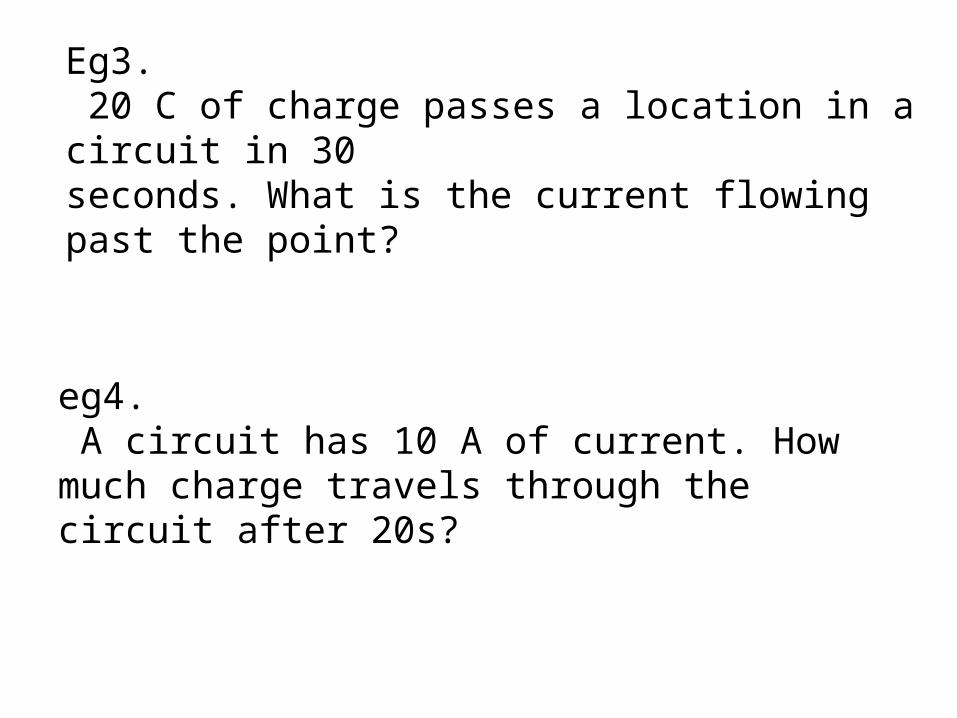
Eg3. 20 C of charge passes a location in a circuit in 30seconds. What is the current flowing past the point?
eg4. A circuit has 10 A of current. How much charge travels through the circuit after 20s?
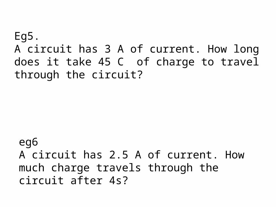
Eg5.A circuit has 3 A of current. How long does it take 45 C of charge to travel through the circuit?
eg6 A circuit has 2.5 A of current. How much charge travels through the circuit after 4s?
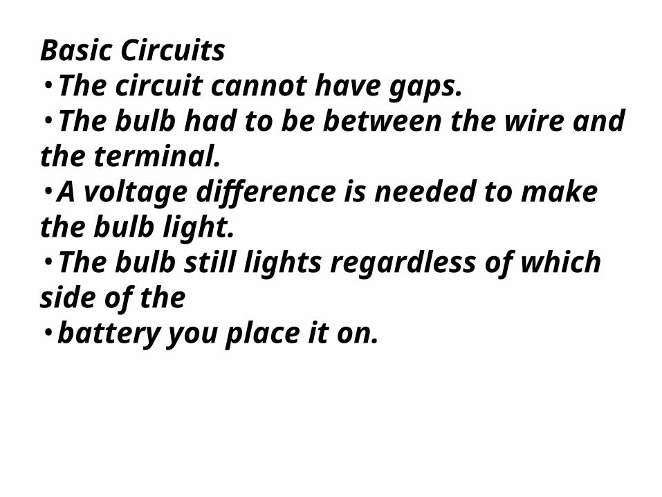
Basic Circuits•The circuit cannot have gaps.•The bulb had to be between the wire and the terminal.•A voltage difference is needed to make the bulb light.•The bulb still lights regardless of which side of the•battery you place it on.
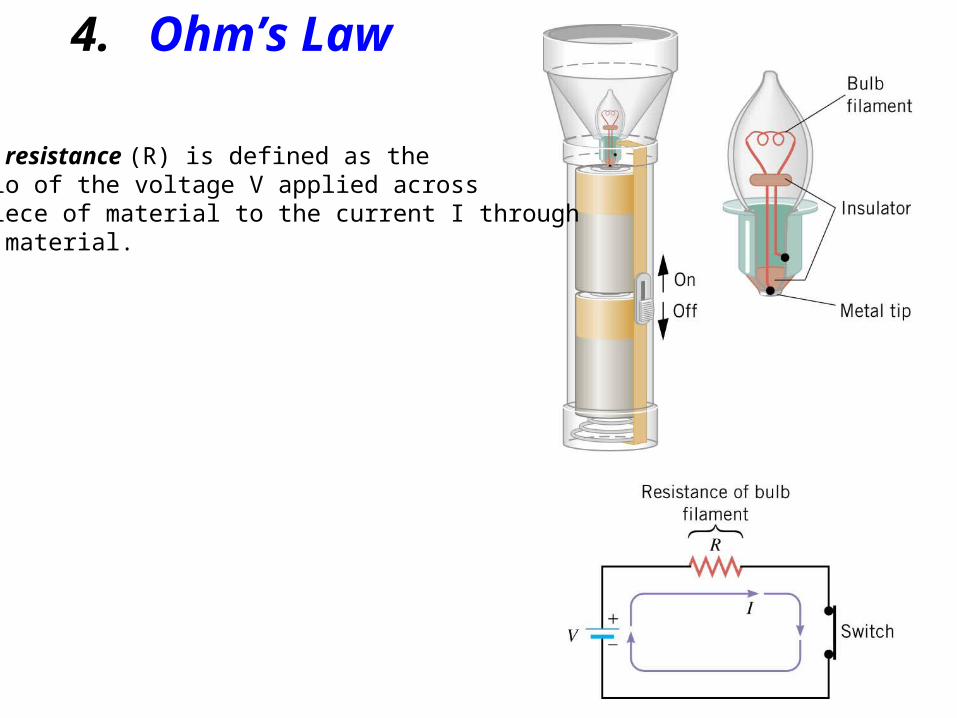
4. Ohm’s Law
The resistance (R) is defined as the ratio of the voltage V applied across a piece of material to the current I throughthe material.

4. Ohm’s Law
OHM’S LAW
The ratio V/I is a constant, where V is thevoltage applied across a piece of materialand I is the current through the material:
SI Unit of Resistance: volt/ampere (V/A) = ohm (Ω)
IRVRI
V or constant
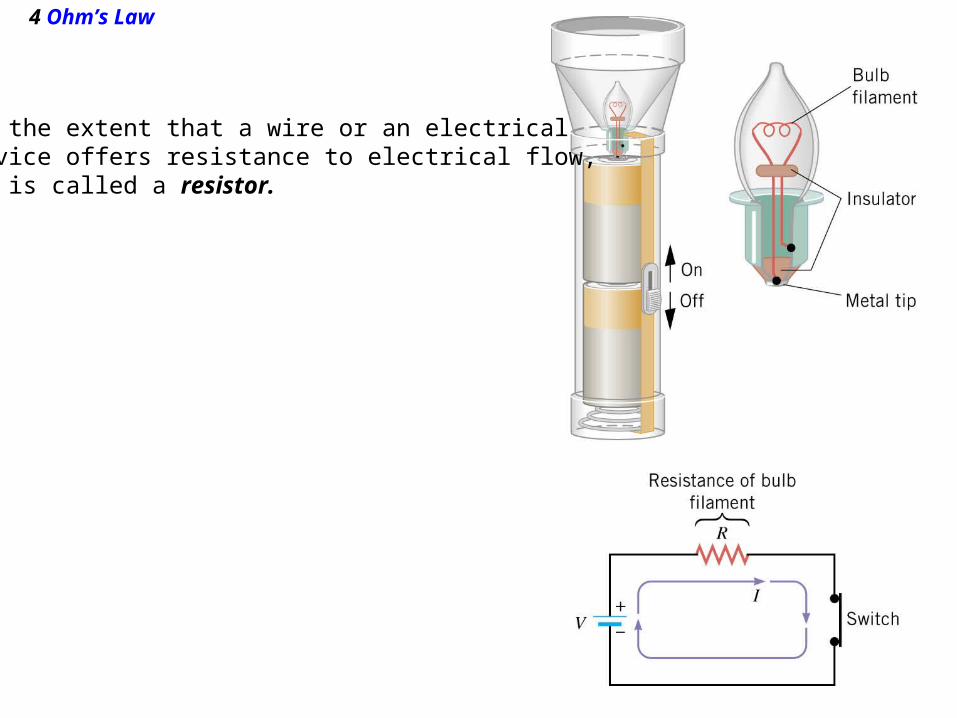
4 Ohm’s Law
To the extent that a wire or an electrical device offers resistance to electrical flow,it is called a resistor.
4 Ohm’s Law
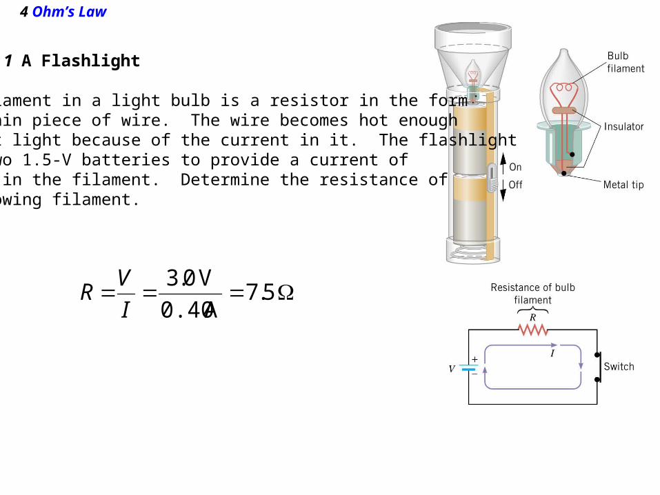
Example 1 A Flashlight
The filament in a light bulb is a resistor in the formof a thin piece of wire. The wire becomes hot enoughto emit light because of the current in it. The flashlightuses two 1.5-V batteries to provide a current of0.40 A in the filament. Determine the resistance ofthe glowing filament.
5.7A 0.40
V 0.3
I
VR
2.A flashlight has a resistance of 30 Ω and is connected by a wire to a 90 V source of voltage. What is the current in the flashlight?
3.What is the current in a wire whose resistance is3 Ω if 1.5 V is applied to it?
5. How much voltage is needed in order to producea 0.70 A current through a 490 Ω resistor?
6. How much voltage is needed in order to producea 0.5 A current through a 150 Ω resistor?
7. What is the resistance of a rheostat coil, if 0.05 A ofcurrent flows through it when 6 V is applied across it?
8. What is the resistance of a rheostat coil, if 20 A of current flows through it when 1000 V is applied across it?

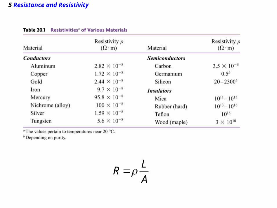
5 Resistance and Resistivity
For a wide range of materials, the resistance of a piece of material of length L and cross-sectional area A is
A
LR
resistivity in units of ohm·meter
the measure of a conductor's resistance to conduct is called its resistivity. Each material has a different resistivity.Resistivity is abbreviated using the Greek letter rho (ρ).Combining what we know about A, L, and ρ, we can find aconductor's total resistance.
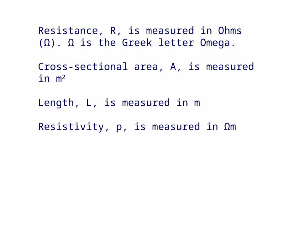
Resistance, R, is measured in Ohms (Ω). Ω is the Greek letter Omega.
Cross-sectional area, A, is measured in m2
Length, L, is measured in m
Resistivity, ρ, is measured in Ωm
5 Resistance and Resistivity
A
LR

What is the resistance of agood conductor?Low; low resistance meansthat electric charges are free to move in a conductor.

Check:Rank the following materials in order of bestconductor to worst conductor.
A Iron, Copper, PlatinumB Platinum, Iron, CopperC Copper, Iron, Platinum
5 Resistance and Resistivity
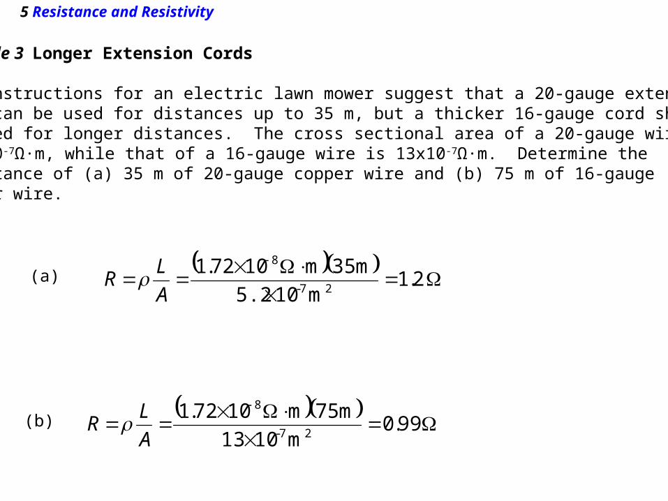
Example 3 Longer Extension Cords
The instructions for an electric lawn mower suggest that a 20-gauge extensioncord can be used for distances up to 35 m, but a thicker 16-gauge cord shouldbe used for longer distances. The cross sectional area of a 20-gauge wire is5.2x10-7Ω·m, while that of a 16-gauge wire is 13x10-7Ω·m. Determine the resistance of (a) 35 m of 20-gauge copper wire and (b) 75 m of 16-gauge copper wire.
2.1m105.2
m 35m1072.127-
8
A
LR (a)
(b)
99.0m1013
m 75m1072.127-
8
A
LR
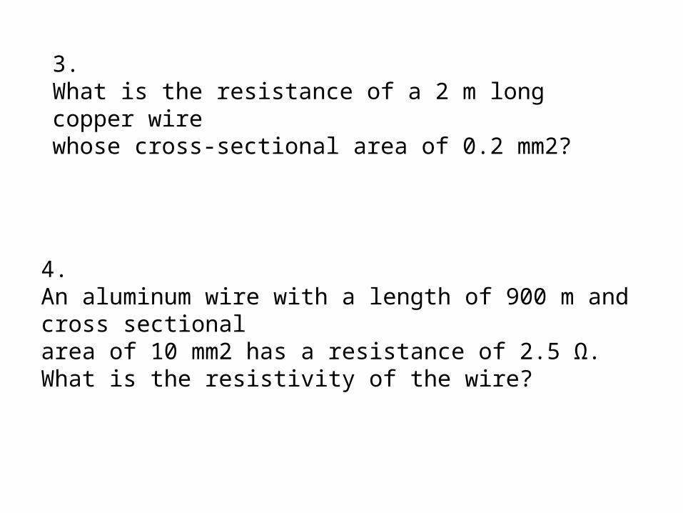
3.What is the resistance of a 2 m long copper wirewhose cross-sectional area of 0.2 mm2?
4. An aluminum wire with a length of 900 m and cross sectionalarea of 10 mm2 has a resistance of 2.5 Ω.What is the resistivity of the wire?
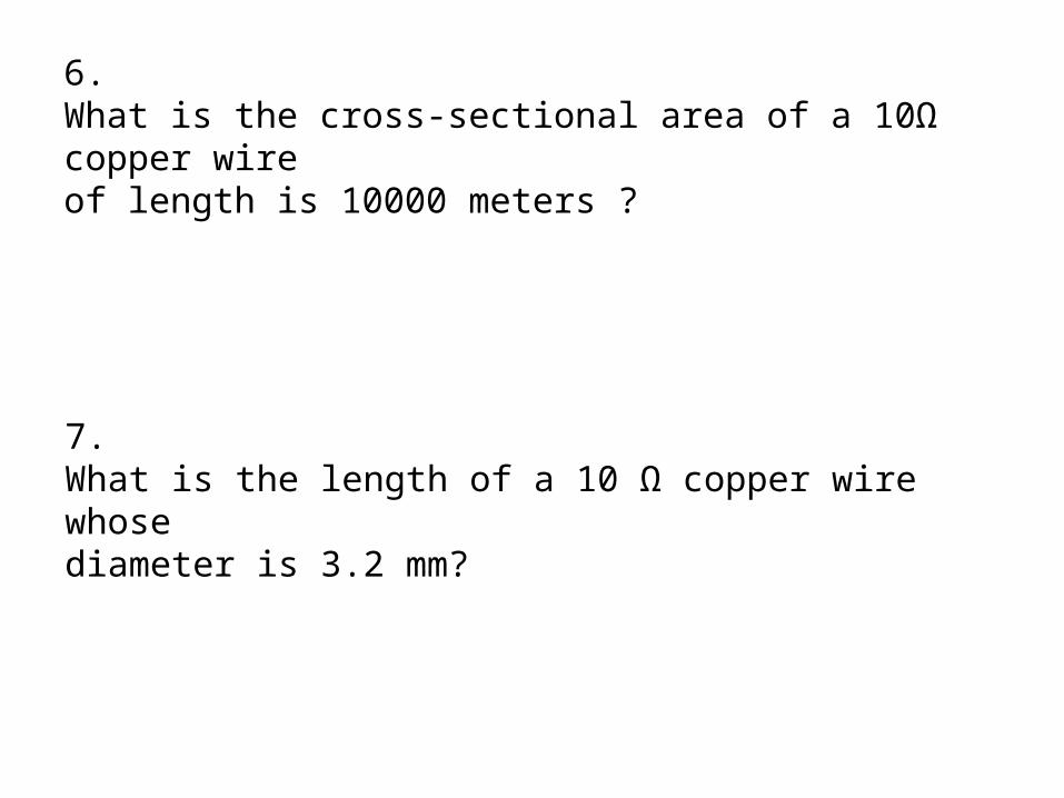
6. What is the cross-sectional area of a 10Ω copper wireof length is 10000 meters ?
7. What is the length of a 10 Ω copper wire whosediameter is 3.2 mm?

20.3 Resistance and Resistivity
Impedance Plethysmography.
calf
2
calf V
L
LV
L
A
LR
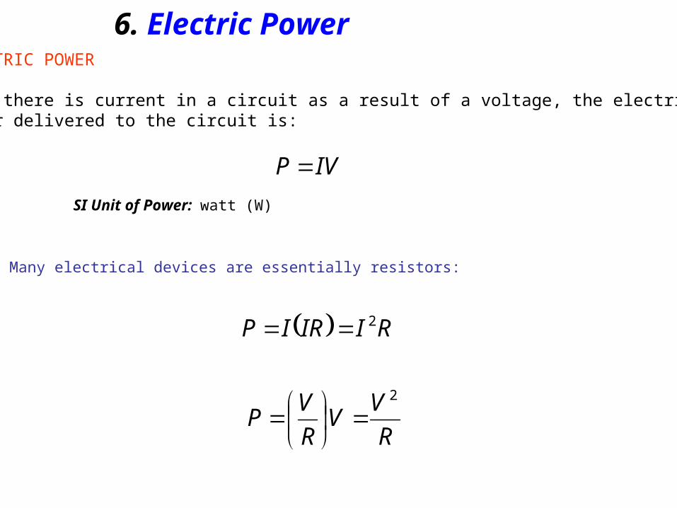
6. Electric Power
IVP
ELECTRIC POWER
When there is current in a circuit as a result of a voltage, the electricpower delivered to the circuit is:
SI Unit of Power: watt (W)
Many electrical devices are essentially resistors:
RIIRIP 2
R
VV
R
VP
2

Electrical PowerLet's think about this anotherway...The water at the top has GPE & KE.As the water falls, it loses GPE and the wheel gets turned, doing work. When the water falls to the bottom it is now slower, having done work.Electric circuits are similar.A charge falls from high voltage to low voltage.In the process of falling energy may be used (light bulb, run a motor, etc).
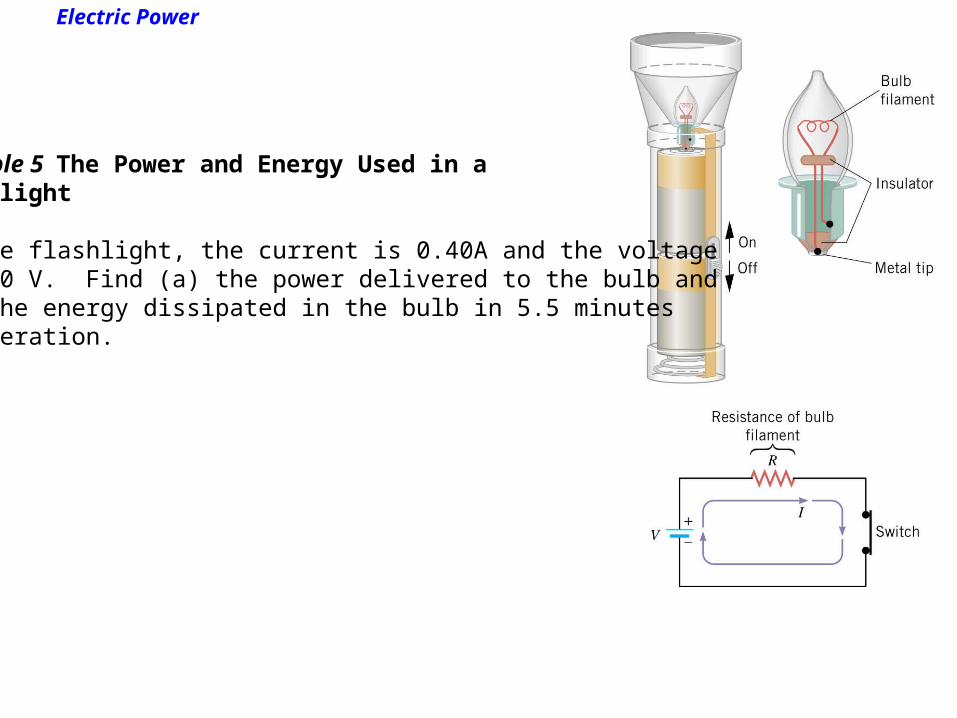
Electric Power
Example 5 The Power and Energy Used in aFlashlight
In the flashlight, the current is 0.40A and the voltageis 3.0 V. Find (a) the power delivered to the bulb and(b) the energy dissipated in the bulb in 5.5 minutesof operation.

20.4 Electric Power
(a)
(b)
W2.1V 0.3A 40.0 IVP
J100.4s 330 W2.1 2PtE

2.A toy car's electric motor has a resistance of 17 Ω; findthe power delivered to it by a 6-V battery.
3. A toy car's electric motor has a resistance of 6 Ω; findthe power delivered to it by a 7-V battery.
4.What is the power consumption of a flash light bulbthat draws a current of 0.28 A when connected to a 6V battery?
5. What is the power consumption of a flash light bulbthat draws a current of 0.33 A when connected to a100 V battery?
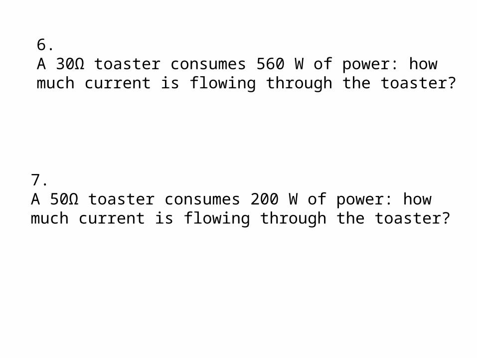
6. A 30Ω toaster consumes 560 W of power: howmuch current is flowing through the toaster?
7. A 50Ω toaster consumes 200 W of power: howmuch current is flowing through the toaster?

8. When 30 V is applied across a resistor it generates 600W of heat: what is the magnitude of its resistance?
9. When 100 V is applied across a resistor it generates200 W of heat: what is the magnitude of its resistance?

Circuit Diagrams
*Note: Circuit diagrams do not show where each part is physically located.
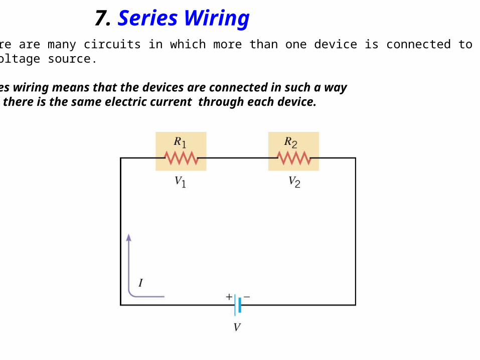
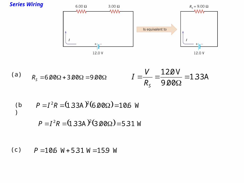
7. Series WiringThere are many circuits in which more than one device is connected toa voltage source.
Series wiring means that the devices are connected in such a waythat there is the same electric current through each device.
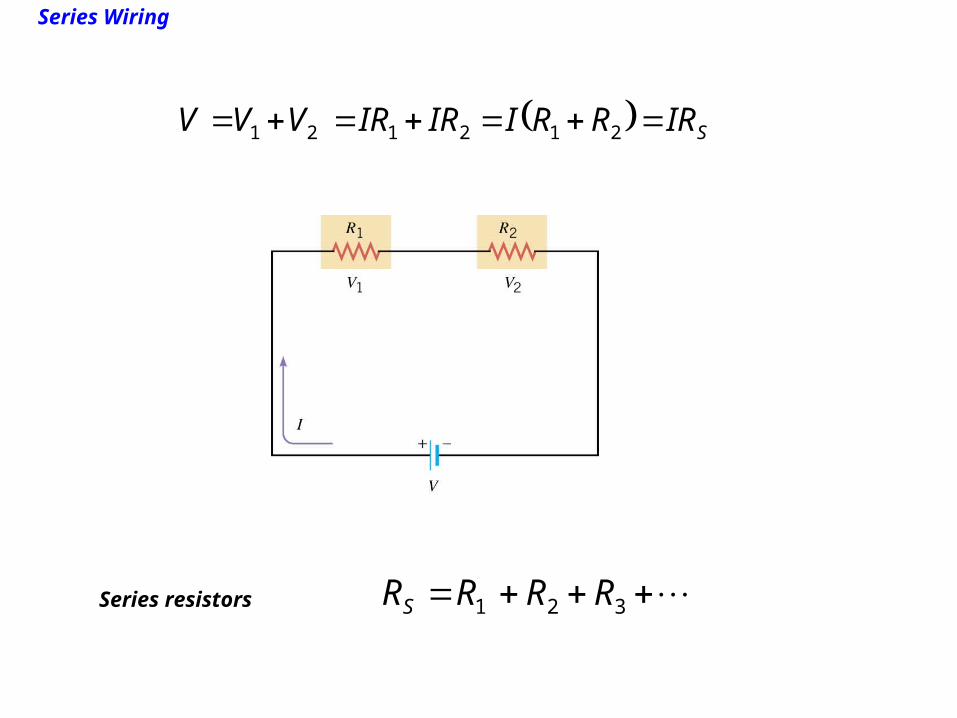
Series Wiring
SIRRRIIRIRVVV 212121
321 RRRRSSeries resistors
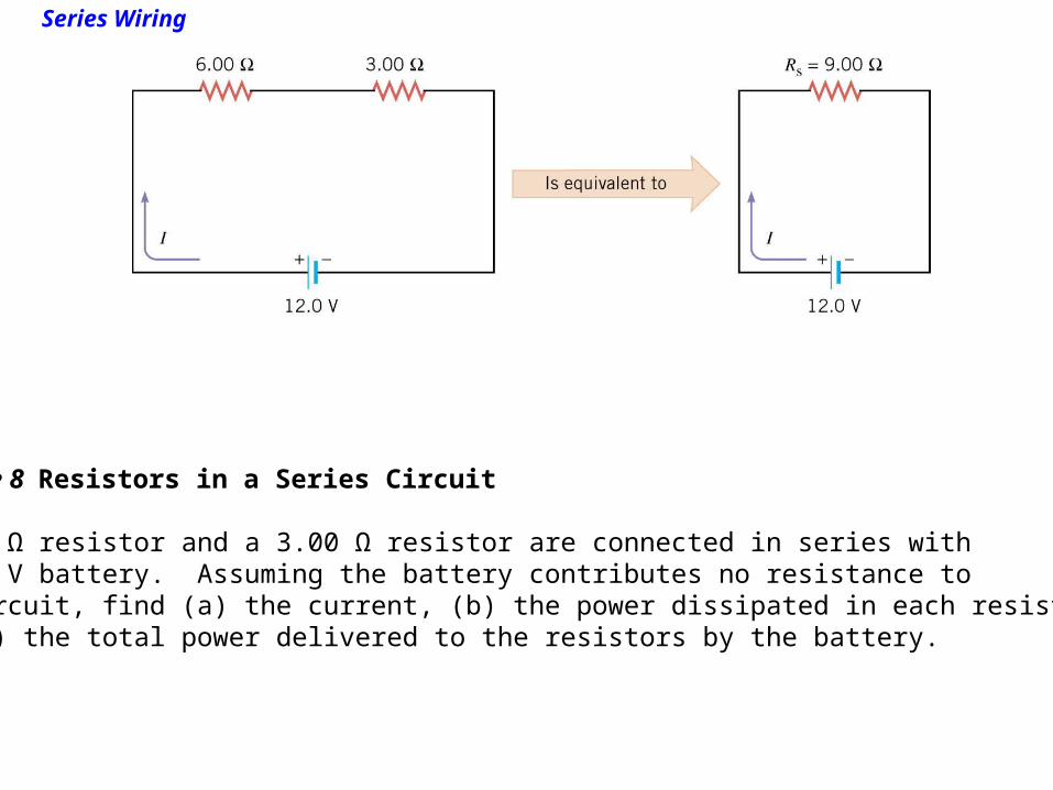
Series Wiring
Example 8 Resistors in a Series Circuit
A 6.00 Ω resistor and a 3.00 Ω resistor are connected in series witha 12.0 V battery. Assuming the battery contributes no resistance to the circuit, find (a) the current, (b) the power dissipated in each resistor,and (c) the total power delivered to the resistors by the battery.
Series Wiring
(a)
(b)
(c)
00.9 00.3 00.6SR A 33.1 00.9
V 0.12
SR
VI
W6.10 00.6A 33.1 22 RIP
W31.5 00.3A 33.1 22 RIP
W9.15 W31.5 W6.10 P
Series Wiring
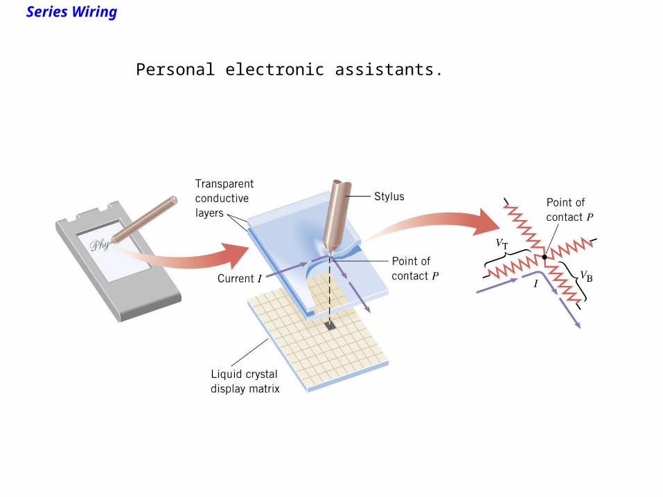
Personal electronic assistants.
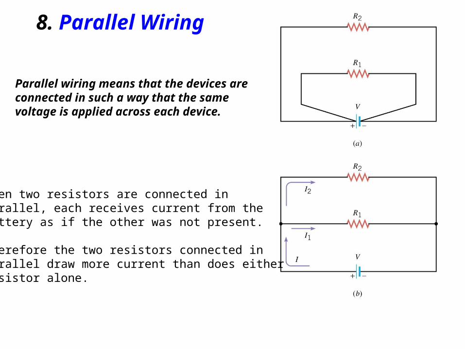
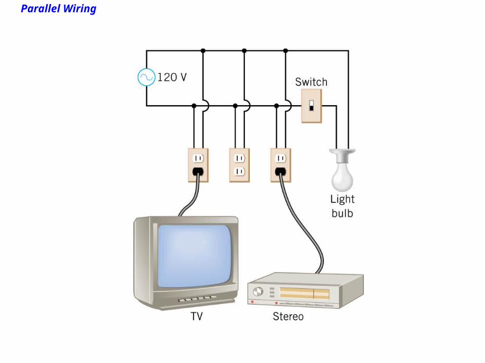
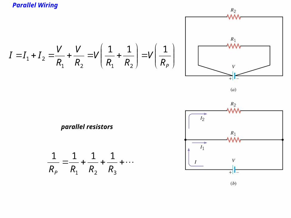
8. Parallel Wiring
Parallel wiring means that the devices areconnected in such a way that the same voltage is applied across each device.
When two resistors are connected in parallel, each receives current from the battery as if the other was not present.
Therefore the two resistors connected inparallel draw more current than does eitherresistor alone.
Parallel Wiring
Parallel Wiring
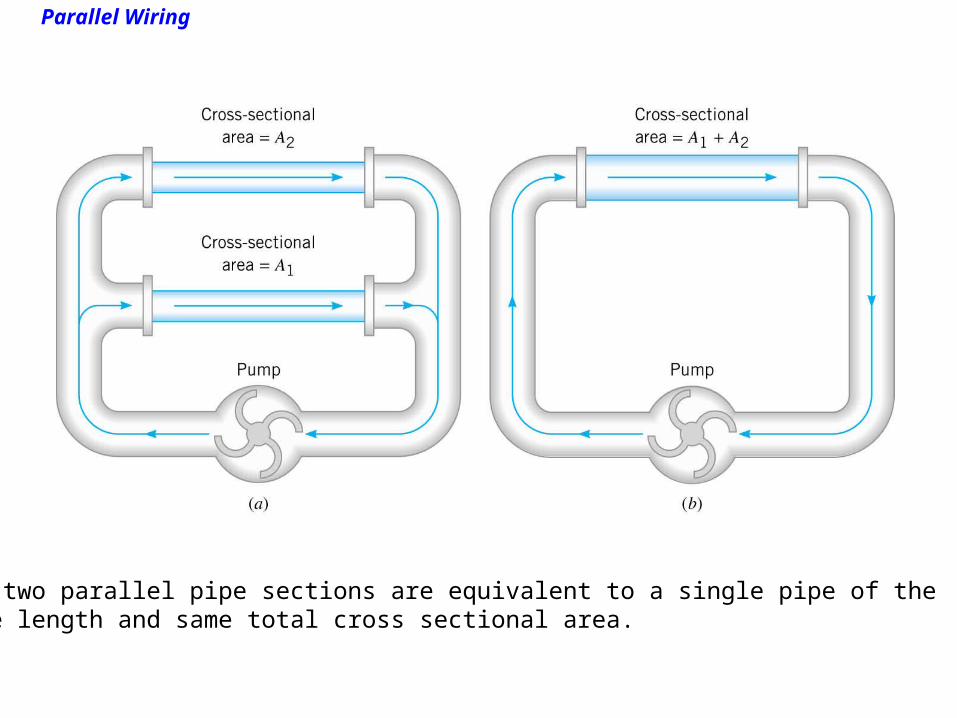
The two parallel pipe sections are equivalent to a single pipe of thesame length and same total cross sectional area.
Parallel Wiring
PRV
RRV
R
V
R
VIII
111
212121
parallel resistors
321
1111
RRRRP
Parallel Wiring
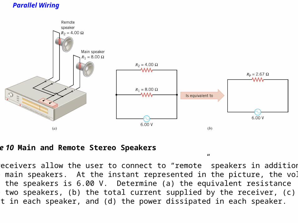
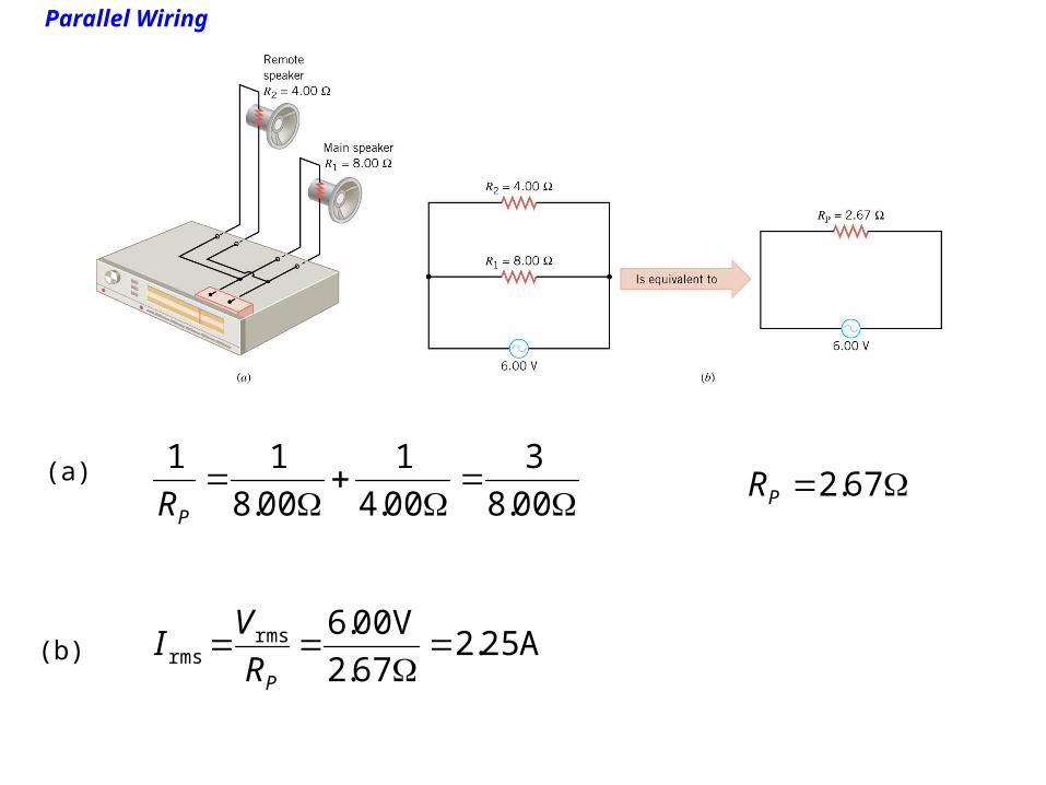
Example 10 Main and Remote Stereo Speakers
Most receivers allow the user to connect to “remote” speakers in additionto the main speakers. At the instant represented in the picture, the voltageacross the speakers is 6.00 V. Determine (a) the equivalent resistanceof the two speakers, (b) the total current supplied by the receiver, (c) thecurrent in each speaker, and (d) the power dissipated in each speaker.
Parallel Wiring
(a)
00.8
3
00.4
1
00.8
11
PR 67.2PR
(b) A 25.2 67.2
V 00.6rmsrms
PR
VI
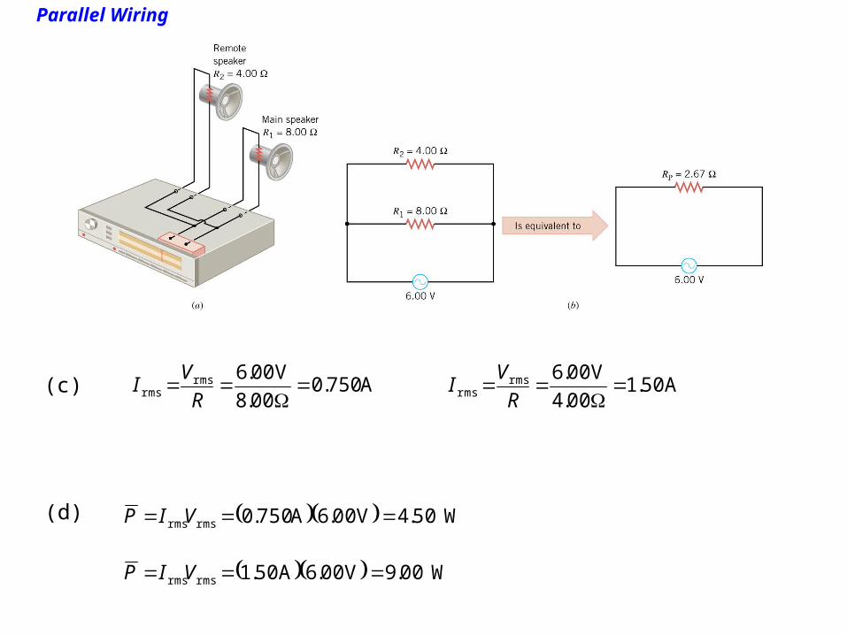
Parallel Wiring
A 750.0 00.8
V 00.6rmsrms
R
VI(c) A 50.1
00.4
V 00.6rmsrms
R
VI
(d) W50.4V 00.6A 750.0rmsrms VIP
W00.9V 00.6A 50.1rmsrms VIP
Parallel Wiring
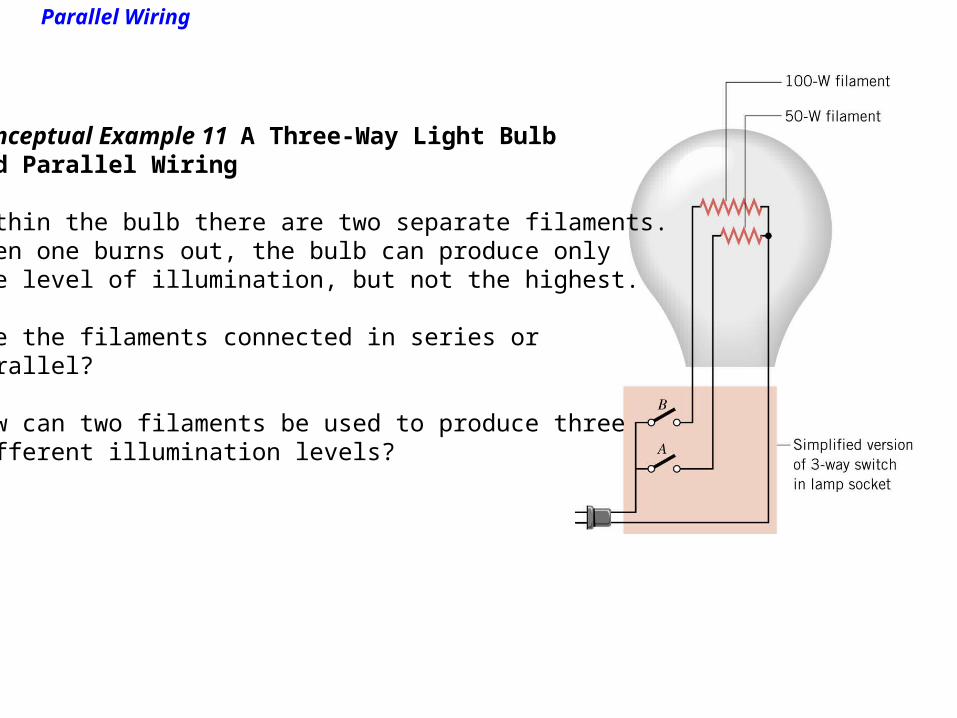
Conceptual Example 11 A Three-Way Light Bulband Parallel Wiring
Within the bulb there are two separate filaments.When one burns out, the bulb can produce onlyone level of illumination, but not the highest.
Are the filaments connected in series orparallel?
How can two filaments be used to produce threedifferent illumination levels?

9. Circuits Wired Partially in Series and Partially in Parallel

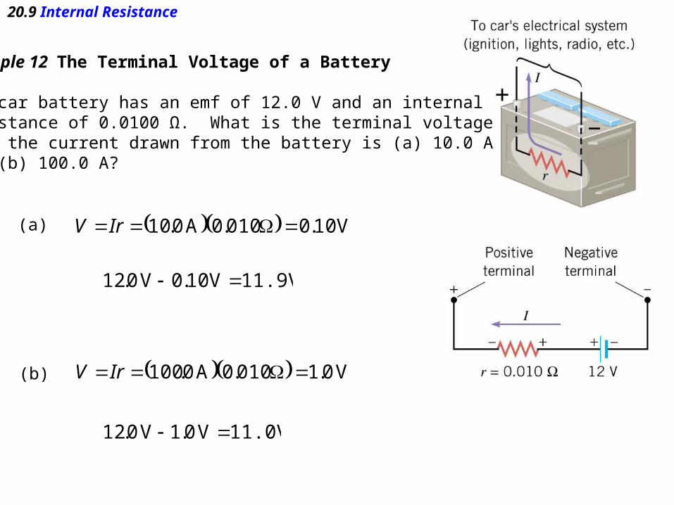
20.9 Internal Resistance
Batteries and generators add some resistance to a circuit. This resistanceis called internal resistance.
The actual voltage between the terminals of a batter is known as theterminal voltage.
20.9 Internal Resistance
Example 12 The Terminal Voltage of a Battery
The car battery has an emf of 12.0 V and an internalresistance of 0.0100 Ω. What is the terminal voltagewhen the current drawn from the battery is (a) 10.0 Aand (b) 100.0 A?
(a) V 10.0 010.0A 0.10 IrV
11.9VV 10.0V 0.12
(b) V 0.1 010.0A 0.100 IrV
11.0VV 0.1V 0.12
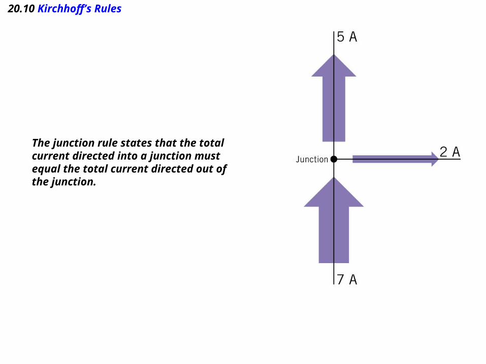
20.10 Kirchhoff’s Rules
The junction rule states that the total current directed into a junction mustequal the total current directed out of the junction.
20.10 Kirchhoff’s Rules
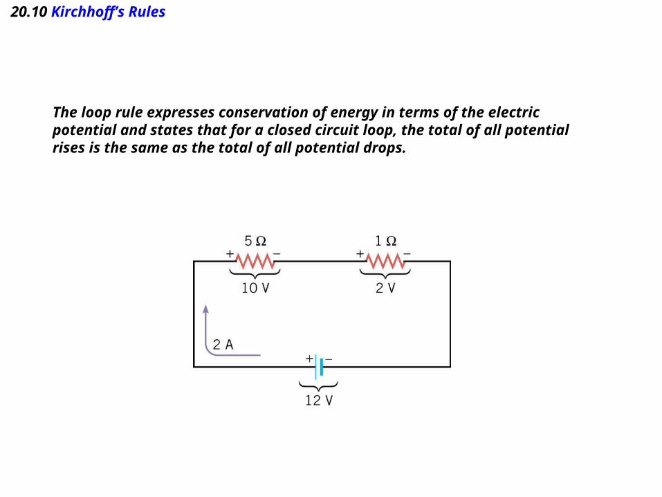
The loop rule expresses conservation of energy in terms of the electric potential and states that for a closed circuit loop, the total of all potentialrises is the same as the total of all potential drops.

20.10 Kirchhoff’s Rules
KIRCHHOFF’S RULES
Junction rule. The sum of the magnitudes of the currents directedinto a junction equals the sum of the magnitudes of the currents directedout of a junction.
Loop rule. Around any closed circuit loop, the sum of the potential dropsequals the sum of the potential rises.
20.10 Kirchhoff’s Rules
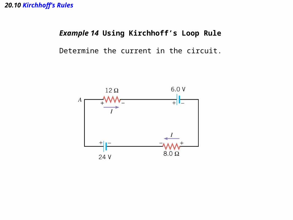
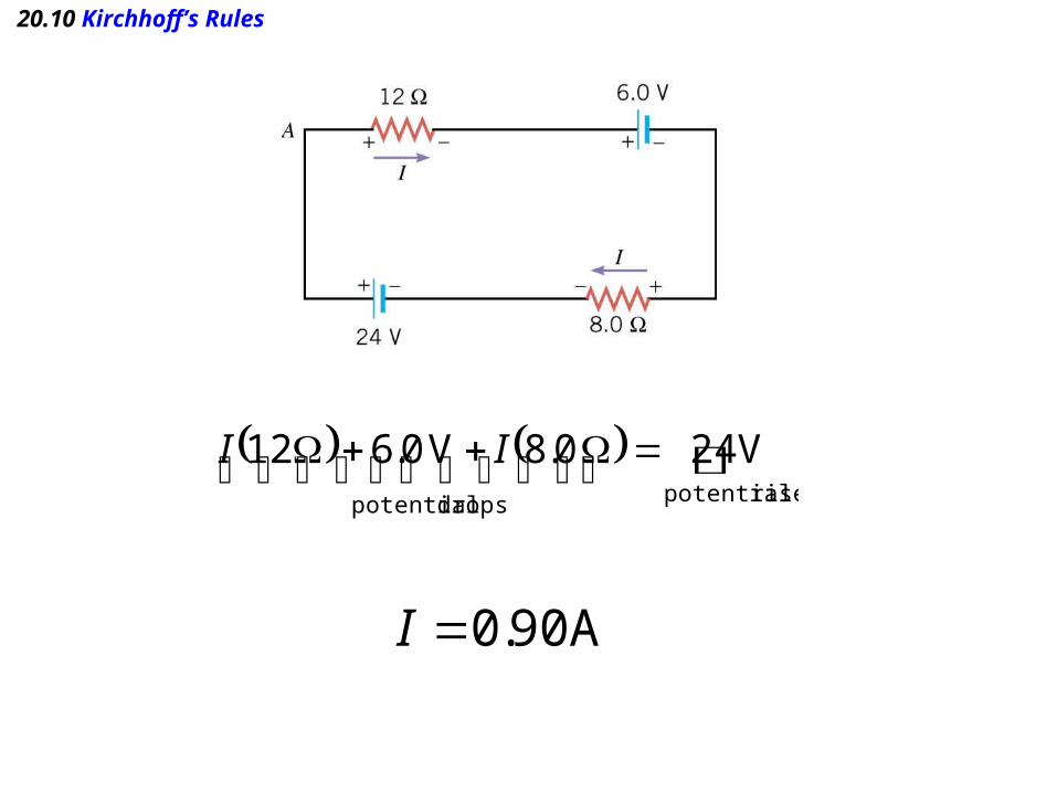
Example 14 Using Kirchhoff’s Loop Rule
Determine the current in the circuit.
20.10 Kirchhoff’s Rules
rises potentialdrops potential
V 24 0.8V 0.6 12 II
A 90.0I
20.10 Kirchhoff’s Rules
20.10 Kirchhoff’s Rules
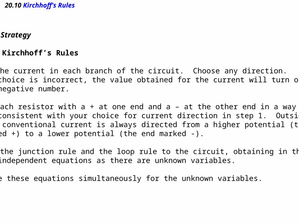
Reasoning Strategy
Applying Kirchhoff’s Rules
1. Draw the current in each branch of the circuit. Choose any direction. If your choice is incorrect, the value obtained for the current will turn outto be a negative number.
2. Mark each resistor with a + at one end and a – at the other end in a waythat is consistent with your choice for current direction in step 1. Outside abattery, conventional current is always directed from a higher potential (theend marked +) to a lower potential (the end marked -).
3. Apply the junction rule and the loop rule to the circuit, obtaining in the processas many independent equations as there are unknown variables.
4. Solve these equations simultaneously for the unknown variables.
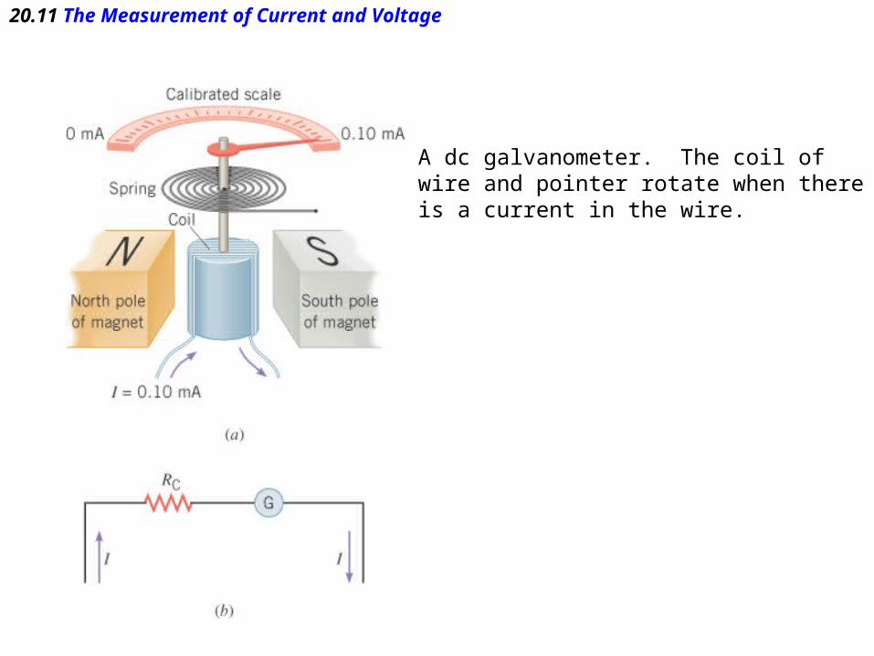
20.11 The Measurement of Current and Voltage
A dc galvanometer. The coil ofwire and pointer rotate when thereis a current in the wire.

20.11 The Measurement of Current and Voltage
An ammeter must be inserted intoa circuit so that the current passesdirectly through it.
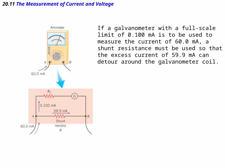
20.11 The Measurement of Current and Voltage
If a galvanometer with a full-scalelimit of 0.100 mA is to be used to measure the current of 60.0 mA, a shunt resistance must be used so thatthe excess current of 59.9 mA can detour around the galvanometer coil.
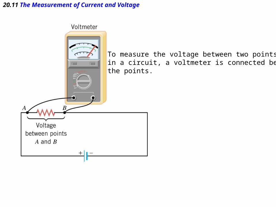
20.11 The Measurement of Current and Voltage
To measure the voltage between two pointsin a circuit, a voltmeter is connected betweenthe points.
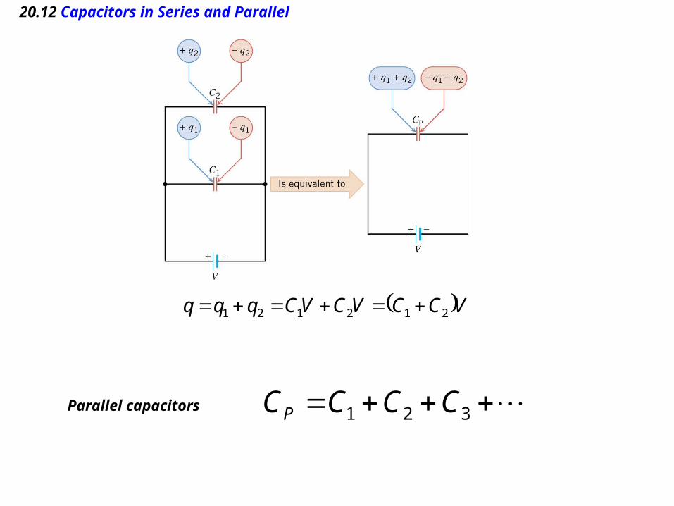
20.12 Capacitors in Series and Parallel
Parallel capacitors 321 CCCCP
VCCVCVCqqq 212121

20.12 Capacitors in Series and Parallel
212121
11
CCq
C
q
C
qVVV
Series capacitors 321
1111
CCCCS
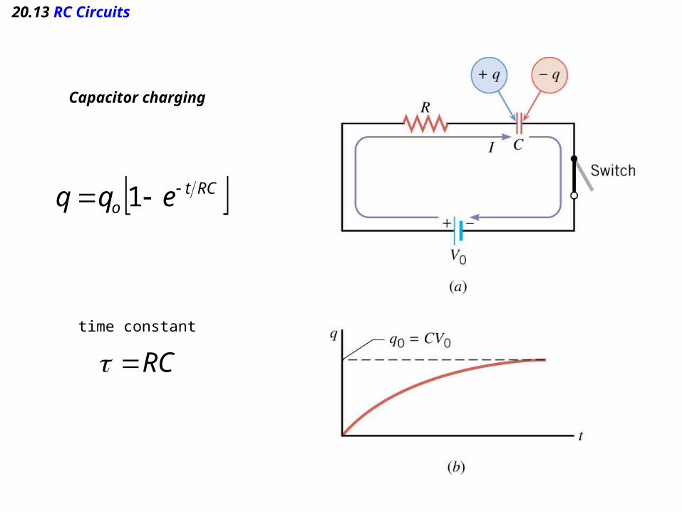
20.13 RC Circuits
Capacitor charging
RCto eqq 1
RCtime constant

20.13 RC Circuits
Capacitor discharging
RCtoeqq
RCtime constant
20.13 RC Circuits
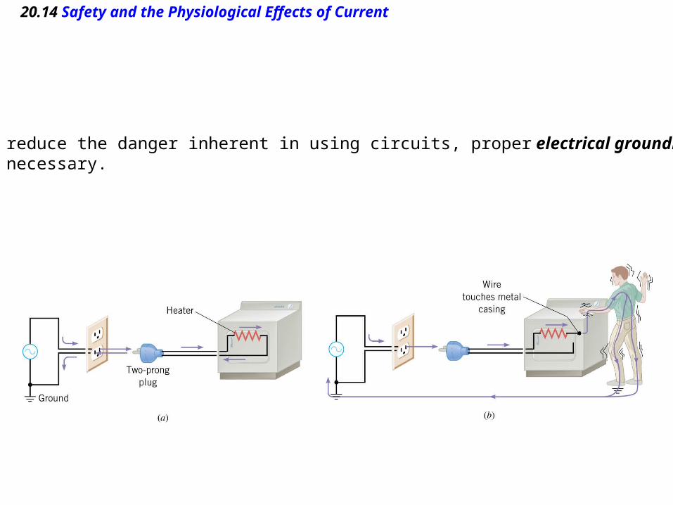
20.14 Safety and the Physiological Effects of Current
To reduce the danger inherent in using circuits, proper electrical grounding is necessary.