Embed Size (px)
Citation preview
1
Chapter 5
AC-to-AC Converters
“Introduction to Modern Power Electronics”, 2nd Ed., John Wiley 2010by
Andrzej M. Trzynadlowski
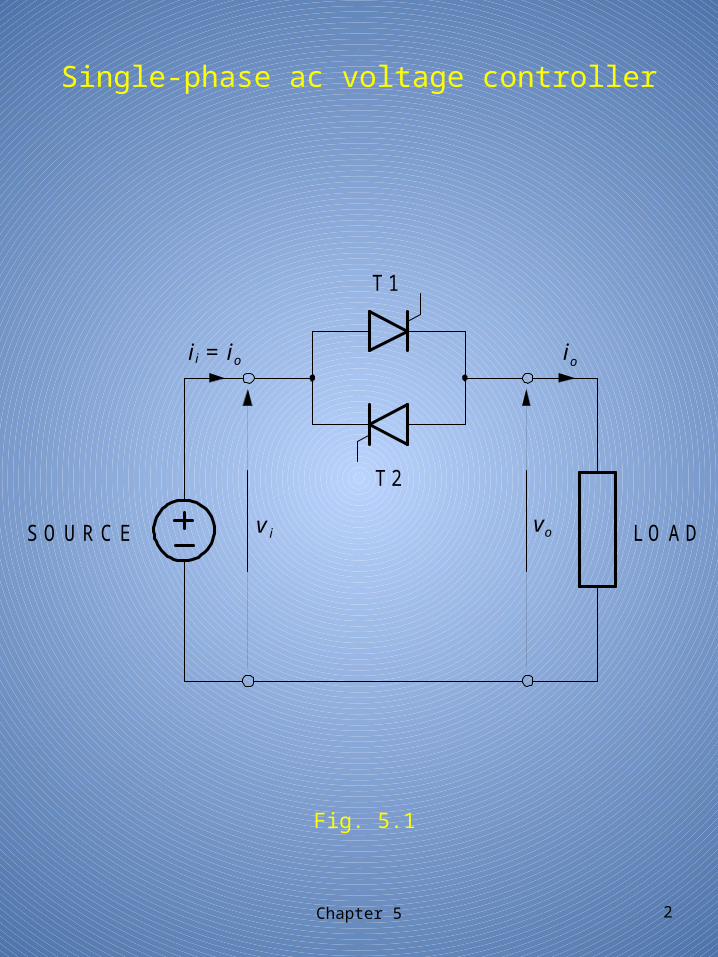
Single-phase ac voltage controller
v
v
S O U R C E L O A D
T 1
T 2
i o
o
= i o i i i
Chapter 5 2
Fig. 5.1
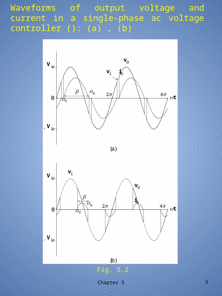
Waveforms of output voltage and current in a single-phase ac voltage controller (): (a) , (b)
Chapter 5 3
Fig. 5.2
Vi,p-
Vi,p
vi
42
vi
Vi,p
4
0 t
(b)
io
vo
e
f
(a)
-
Vi,p
0
f
e
io
vo
2 t
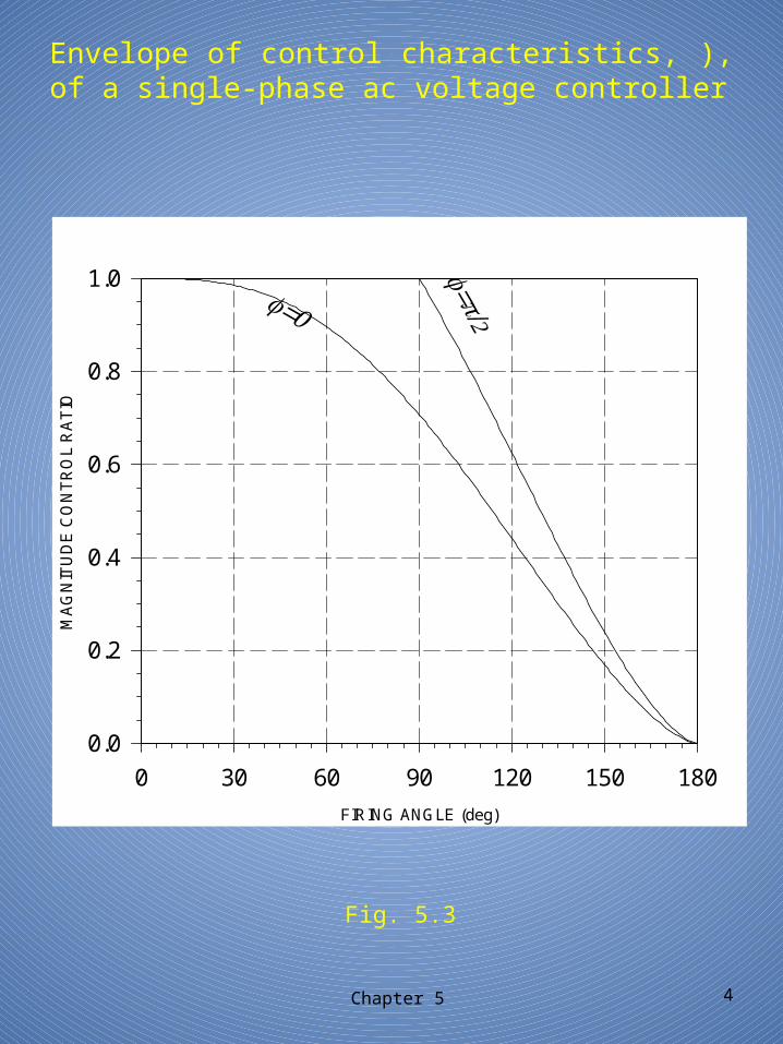
Envelope of control characteristics, ), of a single-phase ac voltage controller
Chapter 5 4
Fig. 5.3
FIRING ANGLE (deg)
0 30 60 90 120 150 180
MA
GN
ITU
DE
CO
NT
RO
L R
AT
IO
0.0
0.2
0.4
0.6
0.8
1.0
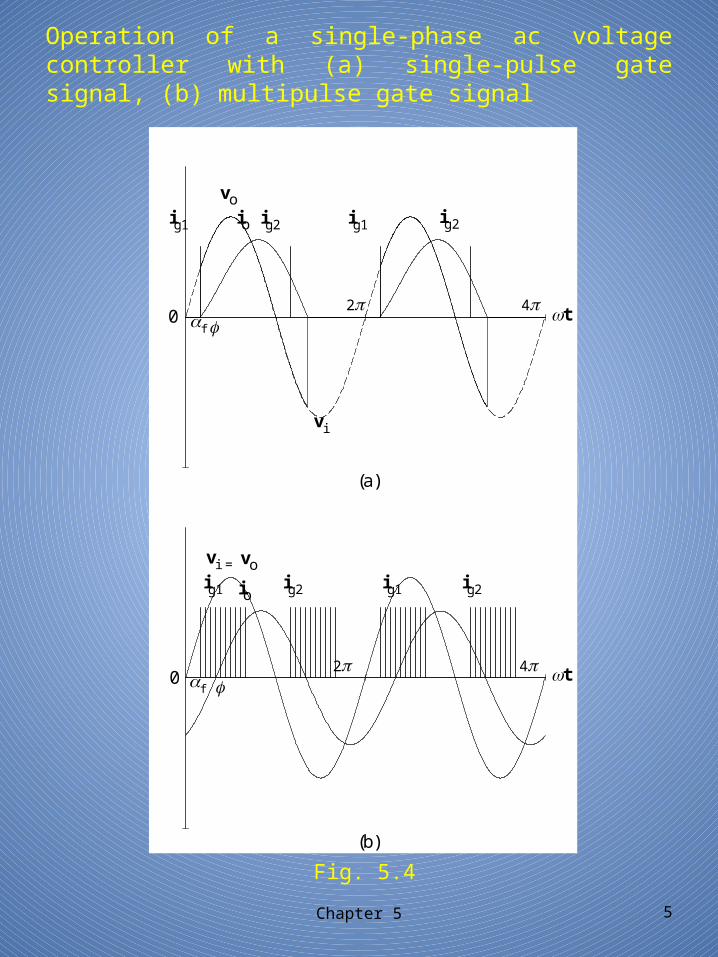
Operation of a single-phase ac voltage controller with (a) single-pulse gate signal, (b) multipulse gate signal
Chapter 5 5
Fig. 5.4
ig2 ig1 ig2 io ig1
ig2 ig2 ig1 ig1
vi
42
vi
4
0 t
(b)
vo
f
(a)
0 f
io
vo
2 t
=
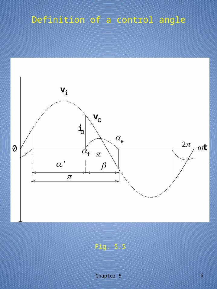
Definition of a control angle
Chapter 5 6
Fig. 5.5
vi
20 t
io
vo
e
f
'
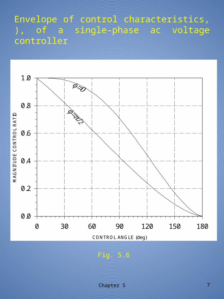
Envelope of control characteristics, ), of a single-phase ac voltage controller
Chapter 5 7
Fig. 5.6
CONTROL ANGLE (deg)
0 30 60 90 120 150 180
MA
GN
ITU
DE
CO
NT
RO
L R
AT
IO
0.0
0.2
0.4
0.6
0.8
1.0
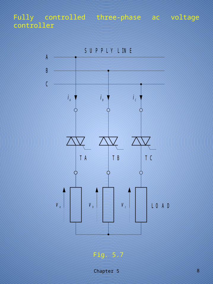
Fully controlled three-phase ac voltage controller
Chapter 5 8
Fig. 5.7
av v vb c
T A T B T C
LO A D
A
B
C
Ai i iB C
S U P P L Y L IN E
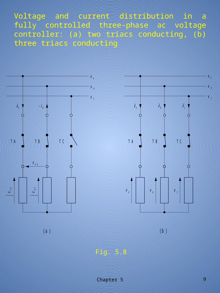
Voltage and current distribution in a fully controlled three-phase ac voltage controller: (a) two triacs conducting, (b) three triacs conducting
Chapter 5 9
Fig. 5.8
v
v
v
B
A
v_1
(a) (b)
C
TBTA TC
vAB
Ai -iB
vAB BA
2 _ 21
TBTA TC
Ai i iB C
Av v vB C
v
v
v
B
A
C
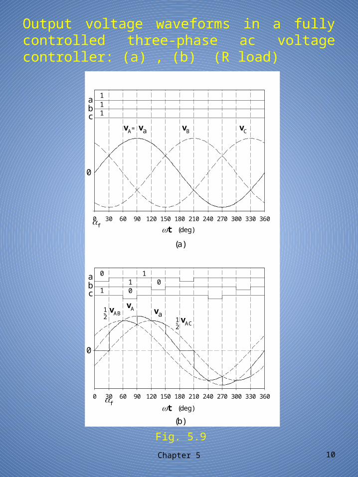
Output voltage waveforms in a fully controlled three-phase ac voltage controller: (a) , (b) (R load)
Chapter 5 10
Fig. 5.9
vAC
vA=
vAB21
21
0
111
vB vCva
cba
f
t (deg)
(a)
t (deg)
(b)
va
0 30 60 90 120 150 180 210 240 270 300 330 360
-
-
f
0
0101
10
cba
vA
0 30 60 90 120 150 180 210 240 270 300 330 360
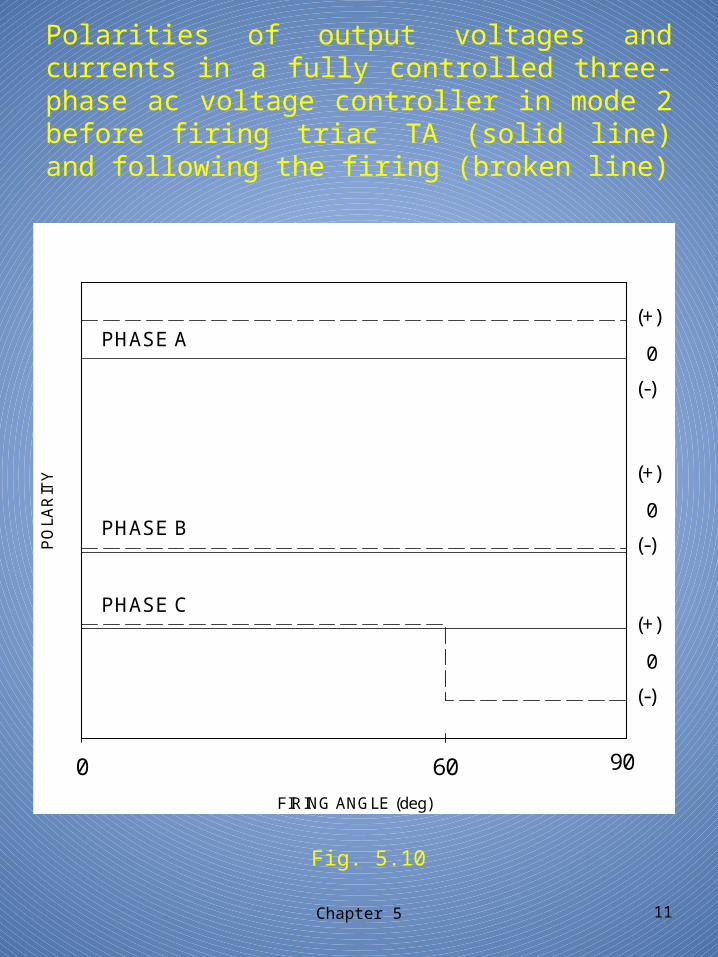
Polarities of output voltages and currents in a fully controlled three-phase ac voltage controller in mode 2 before firing triac TA (solid line) and following the firing (broken line)
Chapter 5 11
Fig. 5.10
(-)
0
(+)
(-)
0
(+)
FIRING ANGLE (deg)
0 60
PO
LAR
ITY
90
PHASE C
PHASE B
PHASE A
(-)
0
(+)
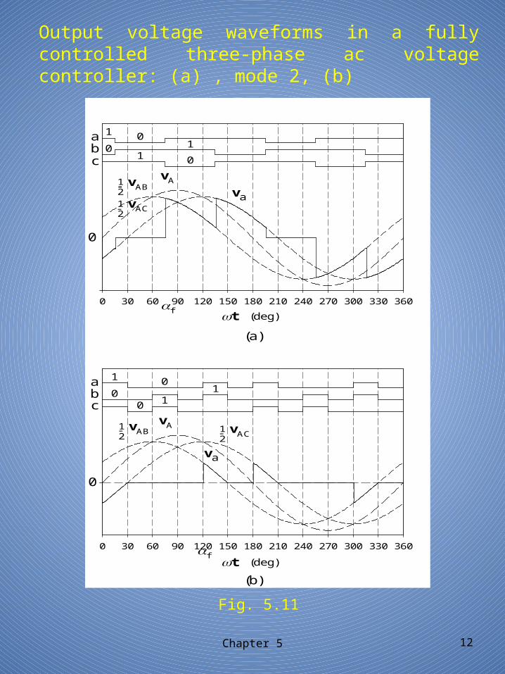
Output voltage waveforms in a fully controlled three-phase ac voltage controller: (a) , mode 2, (b)
Chapter 5 12
Fig. 5.11
vACvAB
21
21
12
1
1
0 10
01
vAC
vABvA
0
va
cba
f
0
t (deg)
(a)
t (deg)
(b)
va
0 30 60 90 120 150 180 210 240 270 300 330 360
--
f
0
1
011
0
cba
vA
0 30 60 90 120 150 180 210 240 270 300 330 360
-2
-
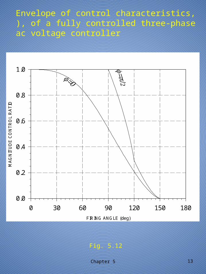
Envelope of control characteristics, ), of a fully controlled three-phase ac voltage controller
Chapter 5 13
Fig. 5.12
FIRING ANGLE (deg)
0 30 60 90 120 150 180
MA
GN
ITU
DE
CO
NT
RO
L R
AT
IO
0.0
0.2
0.4
0.6
0.8
1.0
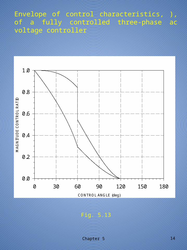
Envelope of control characteristics, ), of a fully controlled three-phase ac voltage controller
Chapter 5 14
Fig. 5.13
CONTROL ANGLE (deg)
0 30 60 90 120 150 180
MA
GN
ITU
DE
CO
NT
RO
L R
AT
IO
0.0
0.2
0.4
0.6
0.8
1.0
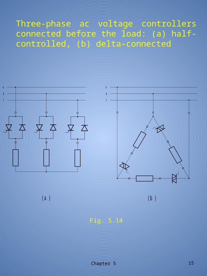
Three-phase ac voltage controllers connected before the load: (a) half-controlled, (b) delta-connected
Chapter 5 15
Fig. 5.14
A
B
C
A
B
C
(a )
(b )
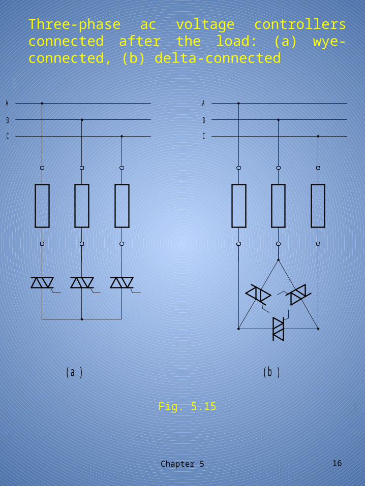
Three-phase ac voltage controllers connected after the load: (a) wye-connected, (b) delta-connected
Chapter 5 16
Fig. 5.15
(a)
(b)
A
B
C
A
B
C
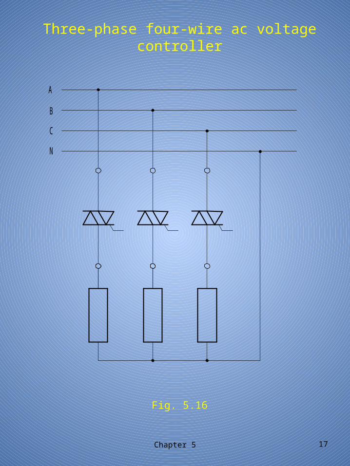
Three-phase four-wire ac voltage controller
Chapter 5 17
Fig. 5.16
A
B
C
N
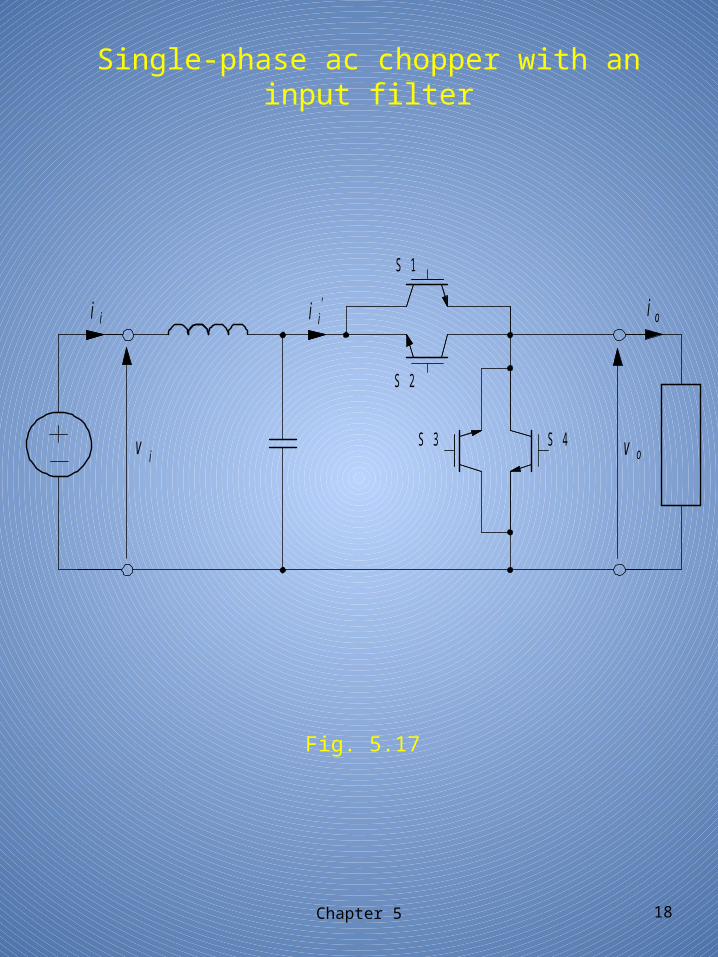
Single-phase ac chopper with an input filter
Chapter 5 18
Fig. 5.17
i i i i'
vov i
i o
S 1
S 2
S 3 S 4
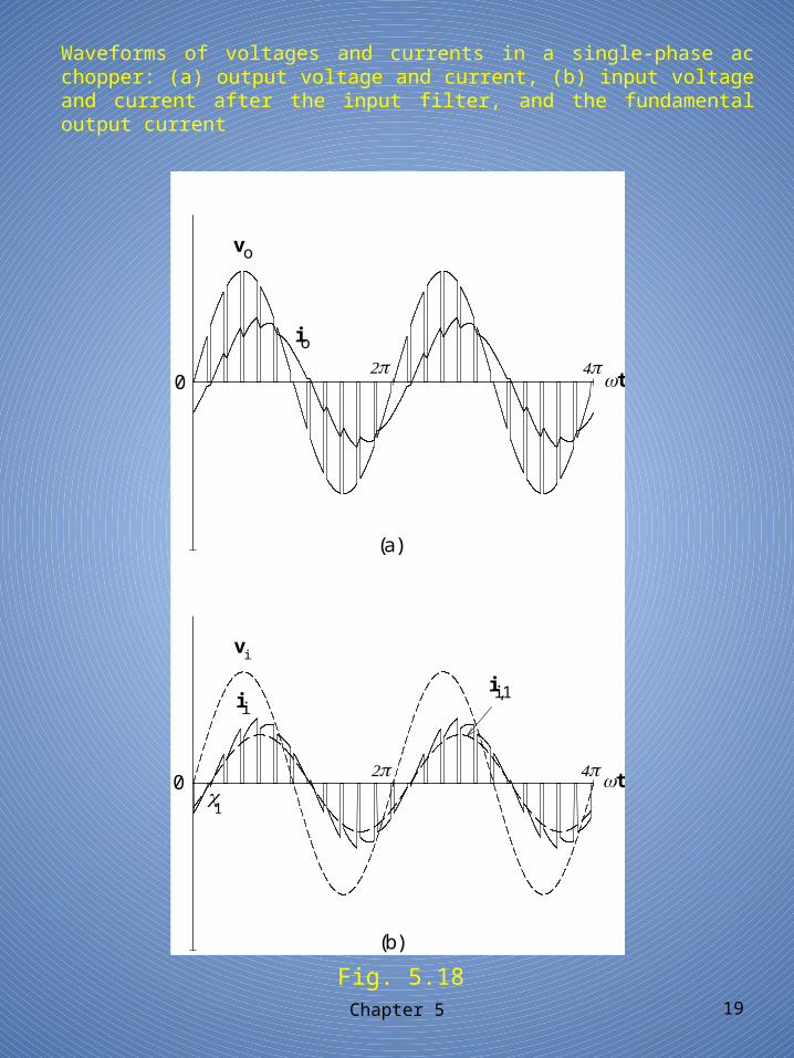
Waveforms of voltages and currents in a single-phase ac chopper: (a) output voltage and current, (b) input voltage and current after the input filter, and the fundamental output current
Chapter 5 19
Fig. 5.18
ii,1ii
io
vo
vi
t0
(a)
1
t0
(b)
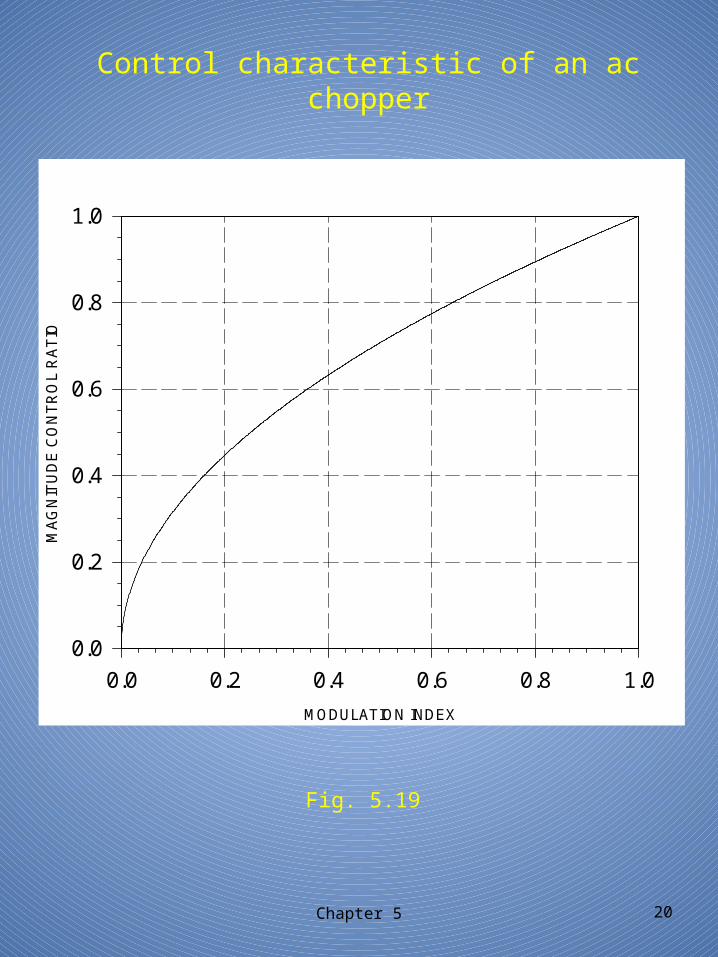
Control characteristic of an ac chopper
Chapter 5 20
Fig. 5.19
MODULATION INDEX
0.0 0.2 0.4 0.6 0.8 1.0
MA
GN
ITU
DE
CO
NT
RO
L R
AT
IO
0.0
0.2
0.4
0.6
0.8
1.0
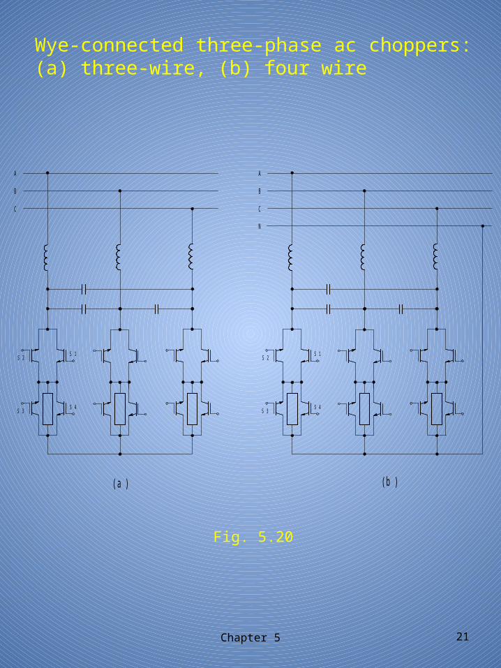
Wye-connected three-phase ac choppers: (a) three-wire, (b) four wire
Chapter 5 21
Fig. 5.20
(b )
S 2 S 1
S 4S 3
S 2 S 1
S 4S 3
(a)
A
B
C
A
B
C
N
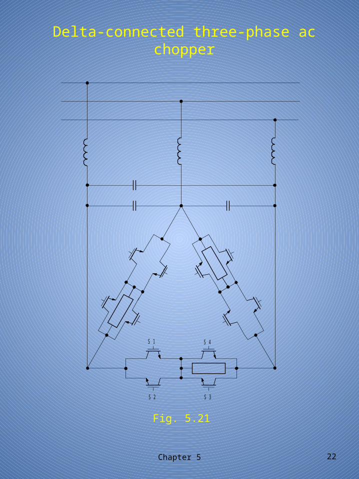
Delta-connected three-phase ac chopper
Chapter 5 22
Fig. 5.21
S1 S4
S2 S3
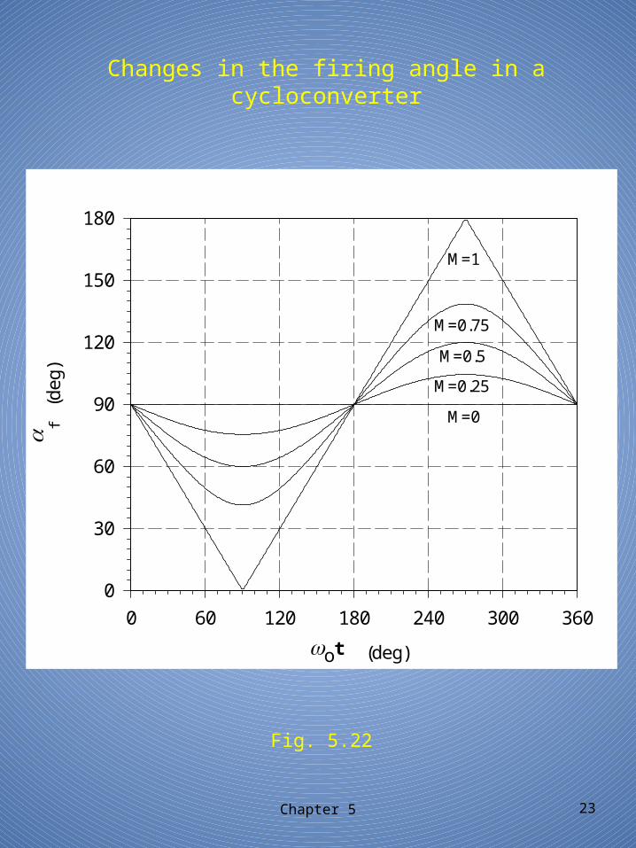
Changes in the firing angle in a cycloconverter
Chapter 5 23
Fig. 5.22
M=0.5
(deg
)
0 60 120 180 240 300 360
0
30
60
90
120
150
180
M=0
M=0.25
M=0.75
M=1
(deg)ot
f
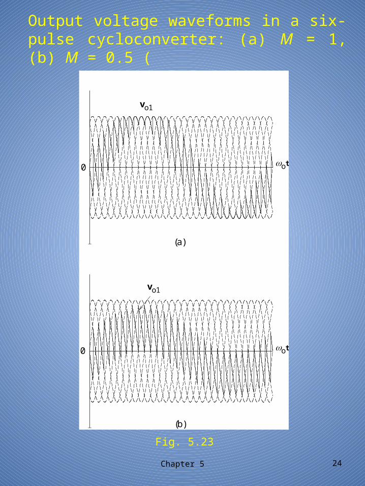
Output voltage waveforms in a six-pulse cycloconverter: (a) M = 1, (b) M = 0.5 (
Chapter 5 24
Fig. 5.23
vo1
vo1
ot
ot0
(a)
0
(b)
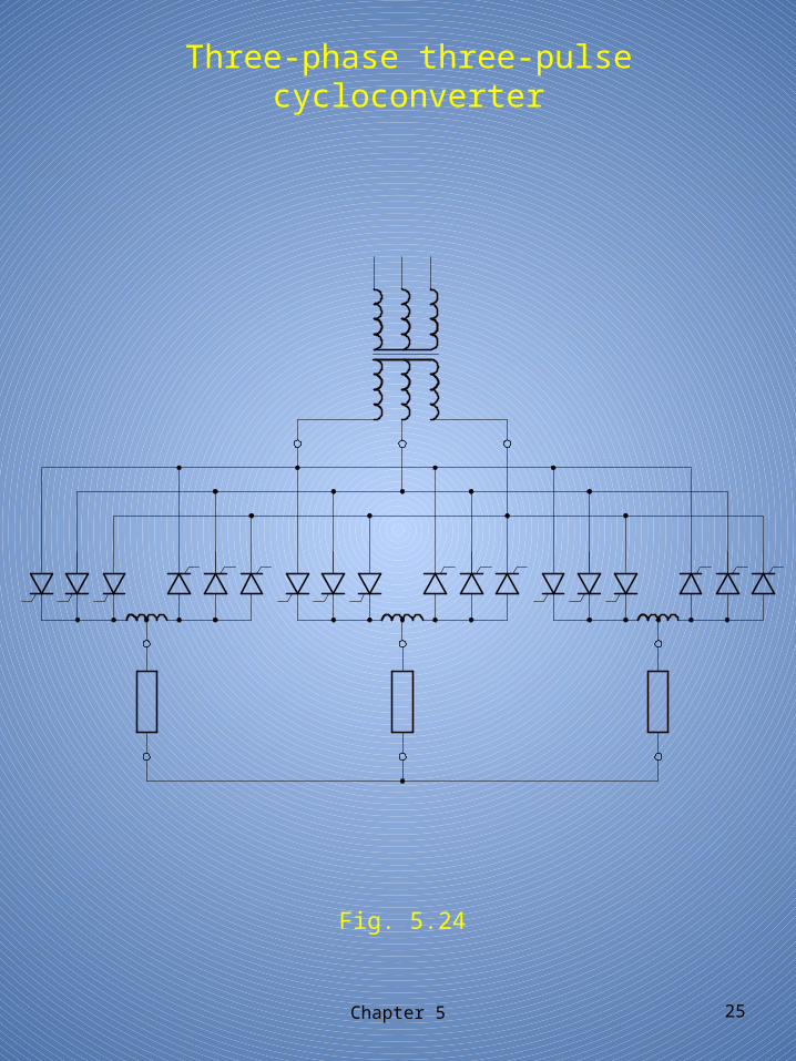
Three-phase three-pulse cycloconverter
Chapter 5 25
Fig. 5.24
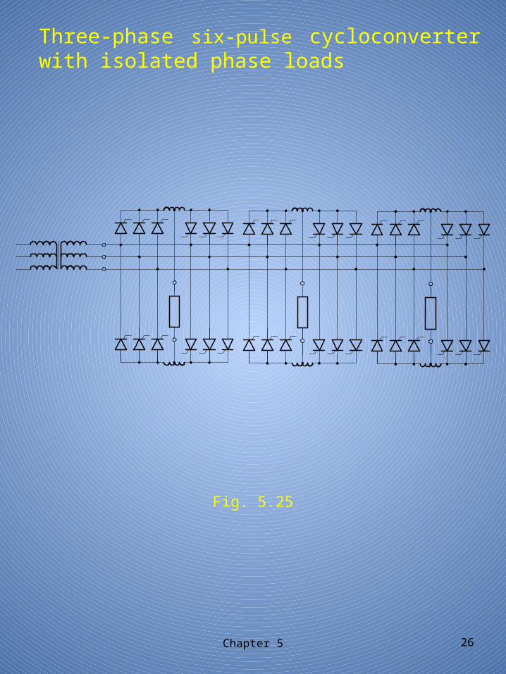
Three-phase six-pulse cycloconverter with isolated phase loads
Chapter 5 26
Fig. 5.25
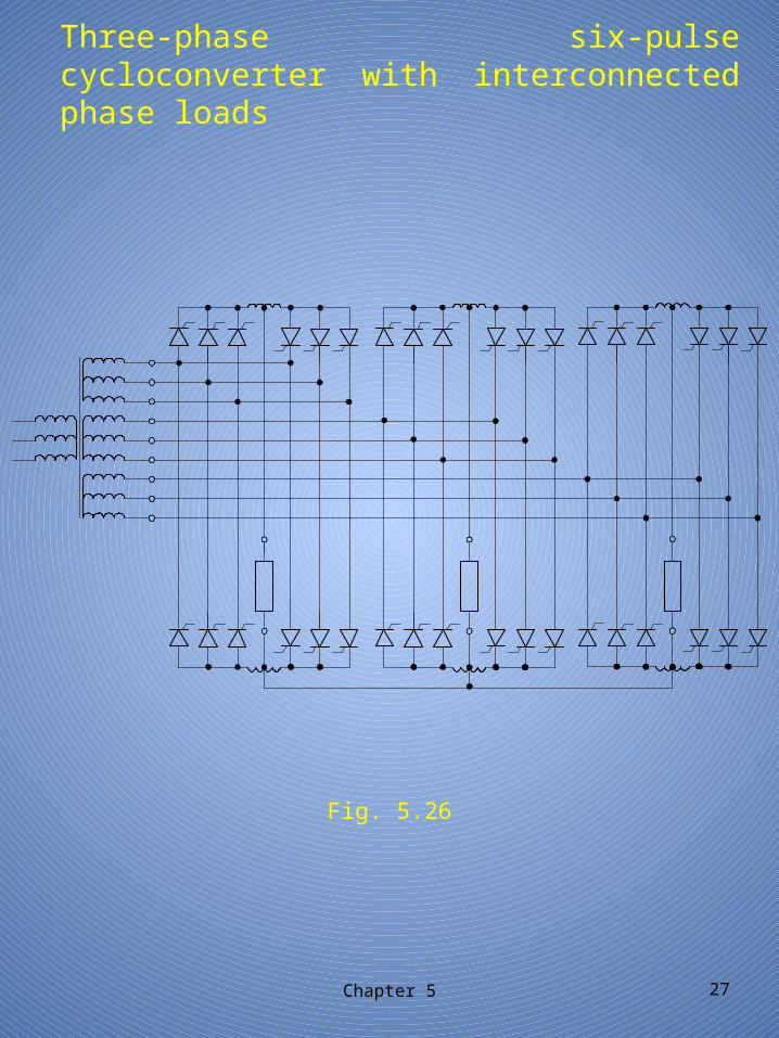
Three-phase six-pulse cycloconverter with interconnected phase loads
Chapter 5 27
Fig. 5.26
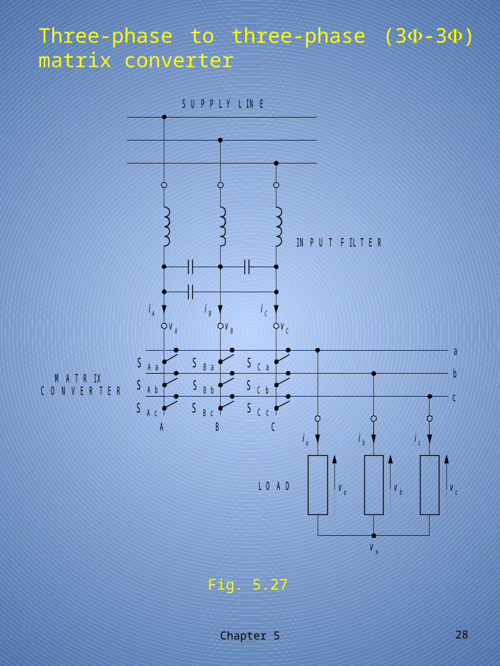
Three-phase to three-phase (3-3) matrix converter
Chapter 5 28
Fig. 5.27
SUPPLY LINE
INPUT FILTER
LOAD
A B C
a
b
cS A b
S A c S C c
S A a
S B b
S B a
S B c
S C a
S C b
iA i iB C
vA v vB C
i i ia b c
v v va b c
vn
MATRIXCONVERTER
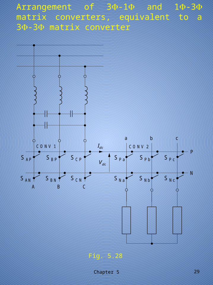
Arrangement of 3-1 and 1-3 matrix converters, equivalent to a 3-3 matrix converter
Chapter 5 29
Fig. 5.28
A B C
a b c
S S
S S
S
SP a P b P c
N a N b N c
P
N
I
V
C O N V 1 C O N V 2
dc
dc
S AP S B P S C P
S AN S B N S C N
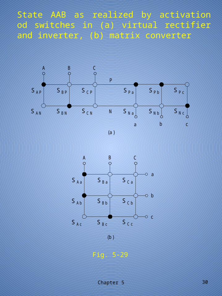
State AAB as realized by activation od switches in (a) virtual rectifier and inverter, (b) matrix converter
Chapter 5 30
Fig. 5-29
S S
S S
S
S
A B C
S S
S S
S
S
ba c
AP BP CP
AN BN CN
Pa Pb Pc
Na Nb Nc
S S
S S
S
S
A B C
S SS
a
b
c
Aa Ba Ca
Ab Bb Cb
Ac Bc Cc
(a)
(b)
P
N
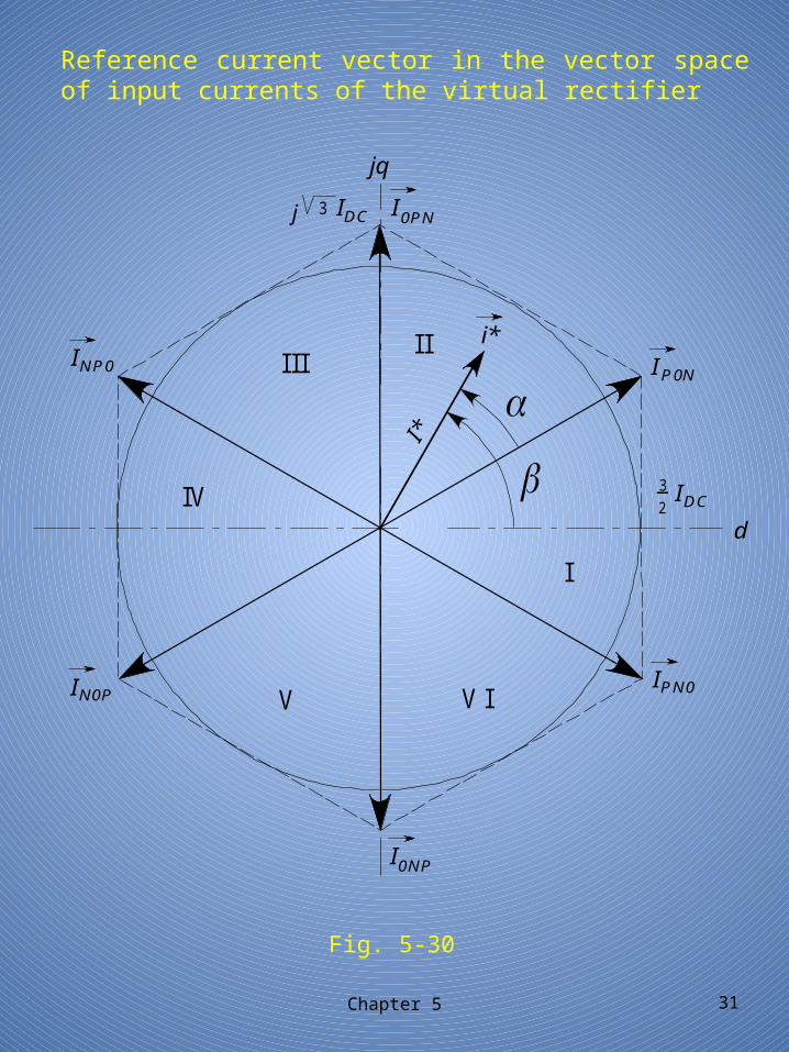
Reference current vector in the vector space of input currents of the virtual rectifier
Chapter 5 31
Fig. 5-30
d
jq
i*
I
I
I
I
I
I II II
IV
V V I
I*
2_3 I
0PN
PN0IN0P
0NP
INP0
Ij 3 DC
DC
P0N
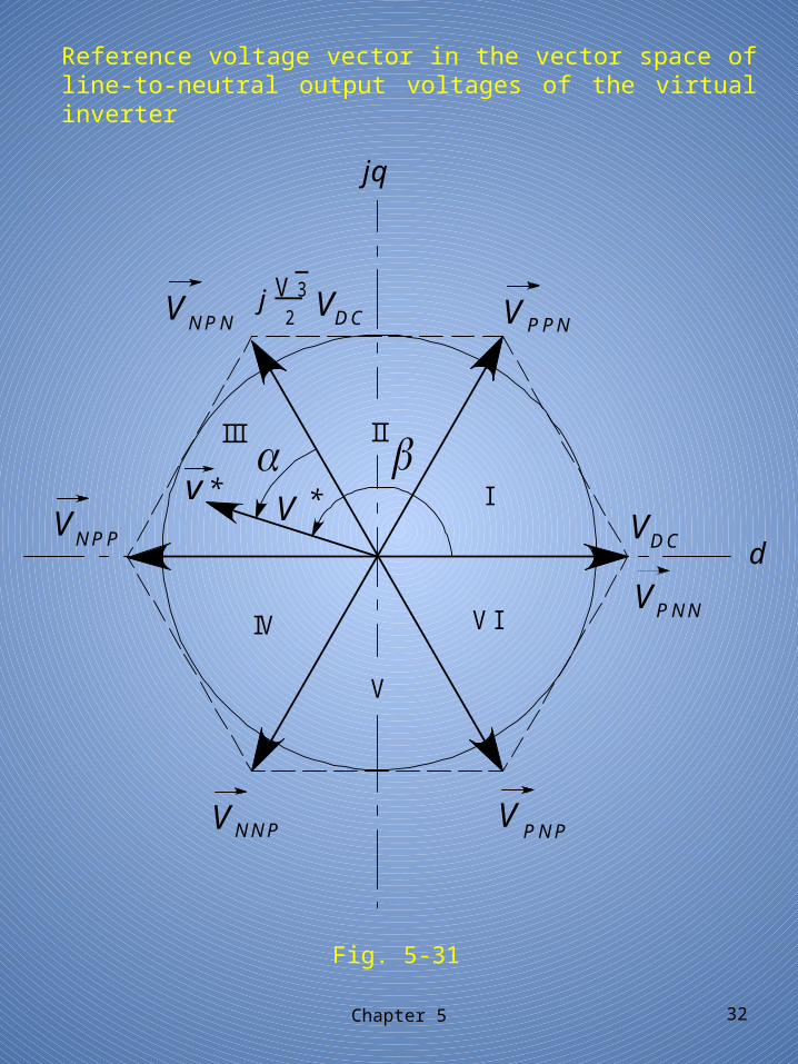
Reference voltage vector in the vector space of line-to-neutral output voltages of the virtual inverter
Chapter 5 32
Fig. 5-31
V
V
jq
d
VI
I
IV
II
V
III V *v *
V
V
V
DC
__V 3
2j VDC PPN
PNN
PNPNNP
VNPP
VNPN
Chapter 5 33
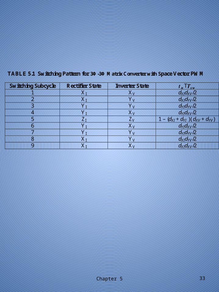
TABLE 5.1 Switching Pattern for 3Φ-3Φ Matrix Converter with Space Vector PWM
Switching Subcycle Rectifier State Inverter State 𝒕𝒏 𝑻𝒔𝒘Τ 1 XI XV dXIdXV/2 2 XI YV dXIdYV/2 3 YI YV dYIdYV/2 4 YI XV dYIdXV/2 5 ZI ZV 1 – (dXI + dYI )( dXV + dYV) 6 YI XV dYIdXV/2 7 YI YV dYIdYV/2 8 XI YV dXIdYV/2 9 XI XV dXIdXV/2
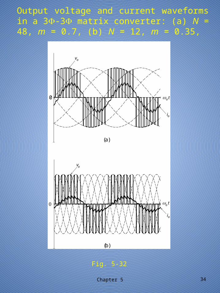
Output voltage and current waveforms in a 3-3 matrix converter: (a) N = 48, m = 0.7, (b) N = 12, m = 0.35,
Chapter 5 34
Fig. 5-32
0
(a)
(b)
i
vo
vo
io
o
o
o
t
t
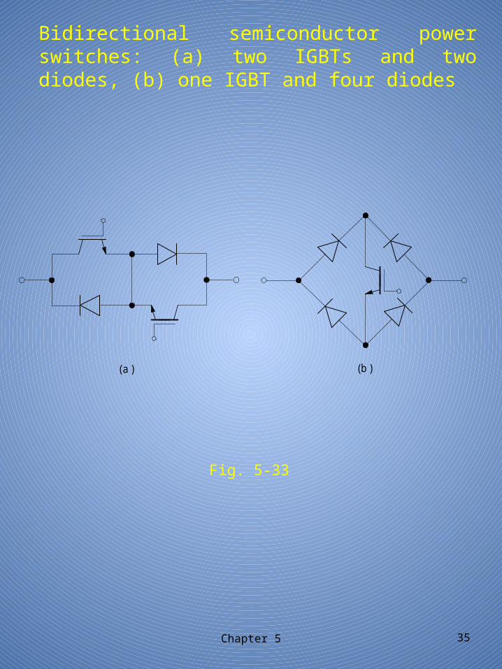
Bidirectional semiconductor power switches: (a) two IGBTs and two diodes, (b) one IGBT and four diodes
Chapter 5 35
Fig. 5-33
(a ) (b )
Chapter 5 36
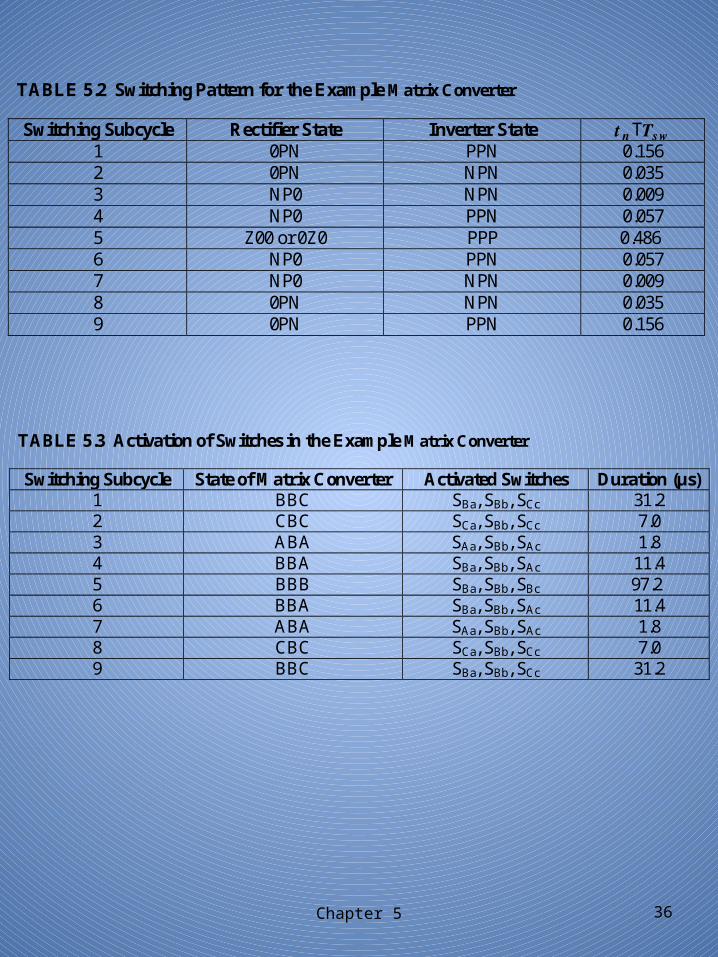
TABLE 5.2 Switching Pattern for the Example Matrix Converter
Switching Subcycle Rectifier State Inverter State 𝒕𝒏 𝑻𝒔𝒘Τ 1 0PN PPN 0.156 2 0PN NPN 0.035 3 NP0 NPN 0.009 4 NP0 PPN 0.057 5 Z00 or 0Z0 PPP 0.486 6 NP0 PPN 0.057 7 NP0 NPN 0.009 8 0PN NPN 0.035 9 0PN PPN 0.156
TABLE 5.3 Activation of Switches in the Example Matrix Converter
Switching Subcycle State of Matrix Converter Activated Switches Duration (µs) 1 BBC SBa, SBb, SCc 31.2 2 CBC SCa, SBb, SCc 7.0 3 ABA SAa, SBb, SAc 1.8 4 BBA SBa, SBb, SAc 11.4 5 BBB SBa, SBb, SBc 97.2 6 BBA SBa, SBb, SAc 11.4 7 ABA SAa, SBb, SAc 1.8 8 CBC SCa, SBb, SCc 7.0 9 BBC SBa, SBb, SCc 31.2
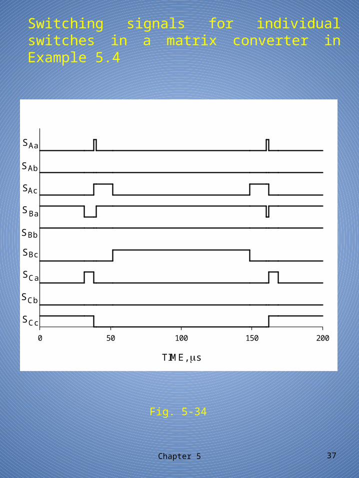
Switching signals for individual switches in a matrix converter in Example 5.4
Chapter 5 37
Fig. 5-34
TIME, s
0 50 100 150 200
S
Aa
Ab
Ac
Ba
Bb
Bc
Ca
Cb
Cc
S
S
S
S
S
S
S
S