Embed Size (px)
Citation preview

ACCESSORIES OF
HYDRAULIC &PNEUMATIC
CIRCUITS
By Prof. S.P.Chaphalkar
CHAPTER - 5

5.1 Filters
Hydraulic Filters
Pneumatic Filters (Air filters)

Hydraulic Filters
The hydraulic system works best when the fluid
is free from impurities & other foreign matter.
The fluid filters are used to remove the smallest
particles of foreign matter from fluid.
The filters used to clean the oil for the hydraulic
system are termed as hydraulic filters.

Types of Hydraulic Filters There are four basic types of filters used in the
hydraulic systems
Mechanical
Absorbent
Adsorbent
Magnetic
Filters are further classified as
Full flow filters
Proportional type filters
Mechanical filters
These contains fine wire mesh closely stocked
metal disc or cloth in the form of bag.
They remove the coarse contaminants such as
dirt, dust, grit & metallic particles.
But these can not remove oil soluble & fine
contaminants.

Absorbent filters
These contains material such as cotton waste,
paper, wood pulp, cloth, asbestos.
They will filter out by mechanical absorption of
coarser particles as well as fine insolubles.
But they do not remove oil soluble oxidation
products.
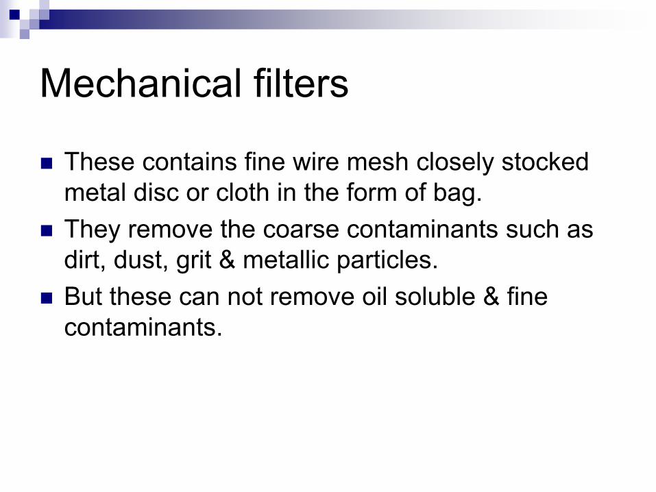
Adsorbent filters
These contains materials such as fuller’s earth, charcoal, activated clay, chemically treated
paper or waste.
It removes both coarser & fine particles.
It also removes insoluble sludges & oil soluble
contaminants.

Magnetic filters
These use stake of magnetized soft steel grids
to remove the ferrous particles flowing through
fluid by magnetism.
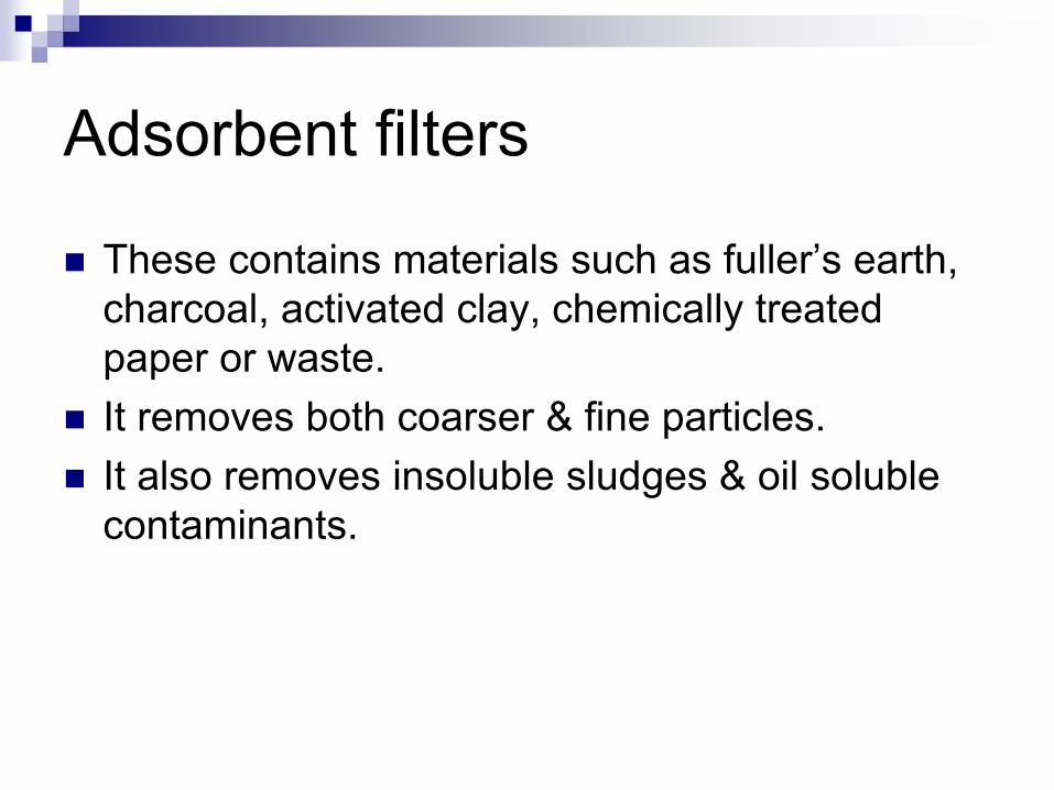
Full flow filters In this all the fluid passes
through filter.
It consist of cylindrical filter
element fitted in a body.
The fluid enters through
the inlet & moves to outer
side of filter element.
Then it passes through
filter element to inner side
where it is connected to
outlet of the filter.

Full flow filters
This filter offers
excessive resistance to
flow as fluid becomes
dirty.
To avoid this resistance,
a spring loaded check
valve is provided, that
opens if pressure
becomes excessive.

Proportional filter
Fig. shows proportional type of filter in which only a portion of fluid passes through the filter.
It operates on the principle of venturi.
The venturi throat causes a pressure drop because it is smaller in diameter than the fluid piping.
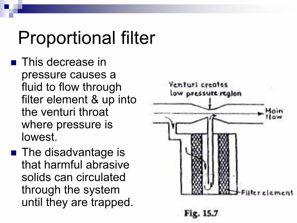
Proportional filter
This decrease in pressure causes a fluid to flow through filter element & up into the venturi throat where pressure is lowest.
The disadvantage is that harmful abrasive solids can circulated through the system until they are trapped.

Pneumatic Filters (Air Filter)
Air filters are used to remove foreign matter from
a air.
The foreign matter may be removed by
centrifuge or cyclone action.
The material for the filter elements are porous
metal, porous stone, felt, resin-impregnated
paper, wool fiber.

Types of air filters
There are three types of air filters
Screen type
Mechanical type
Cyclone type

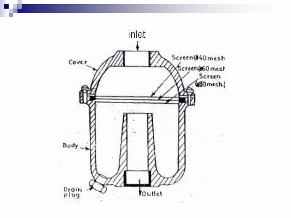
Screen type It consist of a metal
body in which different mesh screens are kept between inlet and outlet.
Here air enters the filter through the inlet & flows through filter element.

Screen type
The filter material is screen where foreign matter is separated from air & then clean air is passed through the outlet of the filter.

Mechanical type filter In mechanical filter the air
enters the filter at the bottom & then passes through the body of filter, while passing it rotates the rotor mounted in a filter at high speed.
Due to this action, the foreign particles, which are heavier than that of air are thrown against the wall of the body by centrifugal force.
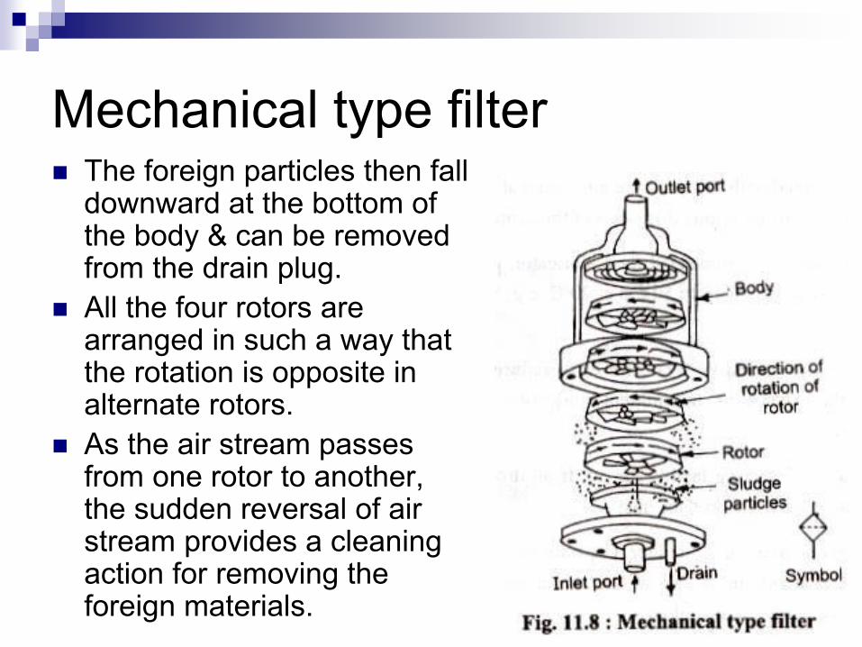
Mechanical type filter The foreign particles then fall
downward at the bottom of the body & can be removed from the drain plug.
All the four rotors are arranged in such a way that the rotation is opposite in alternate rotors.
As the air stream passes from one rotor to another, the sudden reversal of air stream provides a cleaning action for removing the foreign materials.


Cyclone type filter:
it is used for gaseous fluids.
It has deflector plate which
makes the gas to swirl
around the filter element.
Due to this large particles
will be thrown against the
walls of the bowl by
centrifugal force and
collects at the bottom of the
bowl.
The smaller particles are
removed by filter element.

5.2 Hoses & Connectors Requirement of hoses and hose fittings:
1. It should be flexible sufficiently
2. It should be able to work with maximum system pressure
3. It should be provided with proper end fitting
4. It should be oil & weather resistant
5. While assembling, care should be taken to avoid sharp bends, twists, & tension in the hose.
6. Care should be taken while installation regarding the permissible limits of temperature which the hose can withstand.

5.2 Hoses & Connectors Flexible hoses
Hose provide flexible connection for linking two relatively moving machine components.
They are made of nylon, PVC, flexible metallic tubes, elastometric or rubber tube of reinforced construction.

A flexible hose has multilayer cross-section.
The main conductor is made up of a material which is compatible with the fluid to be transmitted.
On outside, it is covered with alternate layers of braided fabric or wire & layer of synthetic rubber.
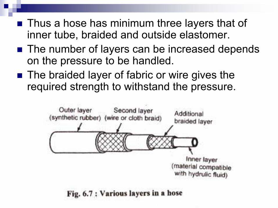
Thus a hose has minimum three layers that of inner tube, braided and outside elastomer.
The number of layers can be increased depends on the pressure to be handled.
The braided layer of fabric or wire gives the required strength to withstand the pressure.

While the layer of synthetic rubber protects the braided layer from corrosion & wear.
Hoses are used in industrial installation due to ease in installation & its characteristics of absorbing pressure shock and machine vibrations.
It required less skill for pipe plumbing, but cost of hose is higher.

Hose Connectors / fittings
1. Permanently attached end fitting:
These may be straight fitting, 450 elbow fitting or
900 elbow fitting.

2. Reusable type end fittings:
These are straight fitting, 450 elbow fitting or 900
elbow fitting.

3. Quick disconnect couplings:
Some application require frequent connecting & disconnecting of fluid supply components.
This requirement is fulfilled by a specially designed connector known as Quick disconnecting coupling.

It permits assembly & disassembly of hose in seconds without need of any special tooling.
The quick disconnect coupling is provided with suitable seals to prevent loss of fluid when two halves are being connected.
It is also provided with suitable check valves to prevent loss when hoses are disconnected.

When the two ports of the coupling are connected the check valve unseated to allow the fluid flow.
The two parts are held together by a locking device.
The locking device is so constructed that a single mechanical movement will unlock the unit & allow the two halves to be parted.

Types of quick disconnect coupling
1. One way shut-off:
In this type check valve is fitted in female part of coupling which prevents the loss of fluid from the fluid source.
The other part does not consist of check valve which leaves the actuator components unloaded.
This cause other side gets contaminated with foreign particles.

2. Two way shut-off
In this type check valves are provided at both the ends of the coupling.
This prevents the loss of fluid when two parts are disconnected also it prevents contamination due to foreign matter.
These couplings are used in earth moving equipments, agricultural machines & portable air tools

Seals & Gaskets
Seals are used to minimize the leakage which in turn prevents the loss of power & reduced efficiency.
Thereby preventing complete failure of components such as pumps or valves.
Seals prevents excessive internal and external leakage and keep the system out of contamination.

Seal is a component made up of some flexible
material when placed at the probable location of
leakage, it gets deformed to fill the clearance
and thus prevents the leakage of hydraulic oil.

Classification of Seals
On the basis of elimination of leakage
A) Positive seals
B) Non-positive seals

Positive seals:- these seals completely stop the leakage. They are primarily used to prevent external leakage.
Ex. Washer used between valve and valve seat.
Non-positive seals:- these are used to prevent any excessive leakage, at the same time they are designed to permit a small amount of leakage.
Ex. Piston rings do not allow the oil to flow from one side of piston to the other at the same time they provide little clearance for formation of lubricating film between cylinder and piston.

On the basis of relative motion between the
parts sealed
Static seal
Dynamic seal

Static seals:- The seals used between the mating parts that do not move relative to each other are termed as static seals.
These seals are compressed between two rigidly connected parts.
These seals makes leak proof joint because of pressure applied in tightening the bolts.
Under pressure the seal material flows and fills the irregularities in the surface making the joint leak-proof.

A static seal may often termed as gasket and is
usually cut from compressible flat sheet material
like paper, cork, rubber or asbestos. The
thickness is ranging from 0.25 mm to 3 mm.
Figure shows static flange joint and rubber seal
moulded in metal ring

O-ring static seal is the simple and most
versatile seal used for static applications. The O-
ring can be made circular, rectangular or U-ring
in cross-section as shown in fig.

Dynamic seals:-
The seal between the mating parts that
move relative to each other is called as
dynamic seals
These seals are subjected to wear as one
of the mating part rubs against the seal
These seals prevents leakage around a
moving component
Ex. Piston rings, O- rings on rotating and
reciprocating shafts
Types of dynamic seals
O-ring
Lipped seals
Piston cup packing
Piston rings
Wiper rings

O-ring :-
It is moulded synthetic rubber seal that has
round cross-section in free state.
It can be used for static as well as dynamic
conditions.
It gives effective sealing strength through a
wide range of pressures, temperatures
and movements.
It provides sealing pressure in both
directions as well low running friction on
moving parts.

It is installed in an annular groove formed
into one of the mating parts.
When the pressure is applied, the O-ring is
forced against the third surface to create a
positive seal. Hence it is capable of
sealing against high pressures.

Lipped seals:
These are used in all types of reciprocating
motion applications.
The U-type of seal is pressure driven
against the mating moving face and the
supporting walls of its recess.

Piston cup packing:
These are designed for pistons in the
reciprocating pump and power cylinders.
These are simple and installed quickly.
In this there is full pressure at lip and
decreasing to zero at the base.

The wall of cylinder supports the pressure at
the cup’s top. For lower pressures and shock loads an
expander is placed inside the expander
packing to force lip against wall.
Ex. Pistons, plungers, rams for sealing
reciprocating motion. In wheel cylinder.

Piston rings:- these are endless, bevel-cut,
butt-cut and step-cut. The piston rings are
installed in a groove cut in piston to
prevent leakage of fluid past the cylinder.
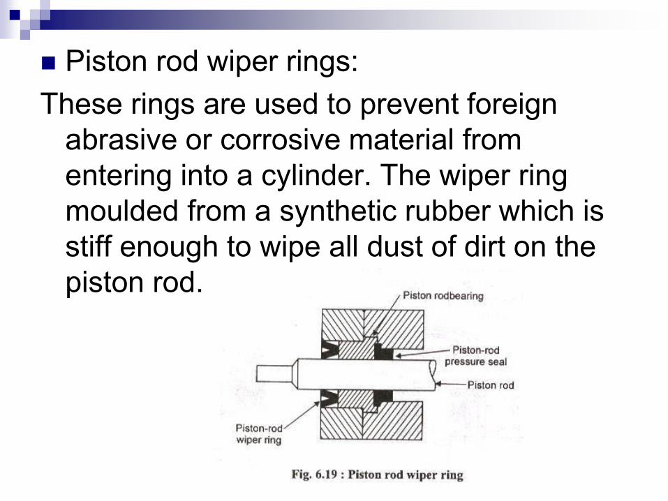
Piston rod wiper rings:
These rings are used to prevent foreign
abrasive or corrosive material from
entering into a cylinder. The wiper ring
moulded from a synthetic rubber which is
stiff enough to wipe all dust of dirt on the
piston rod.