Embed Size (px)
Citation preview
© 2007 – 2010, Cisco Systems, Inc. All rights reserved. Cisco PublicCourse v6 Chapter #
1
Chapter 5:Maintaining and Troubleshooting Routing Solutions
CCNP TSHOOT: Maintaining and Troubleshooting IP Networks

Chapter #2© 2007 – 2010, Cisco Systems, Inc. All rights reserved. Cisco Public
Troubleshooting Network Layer Connectivity
Chapter #3© 2007 – 2010, Cisco Systems, Inc. All rights reserved. Cisco Public
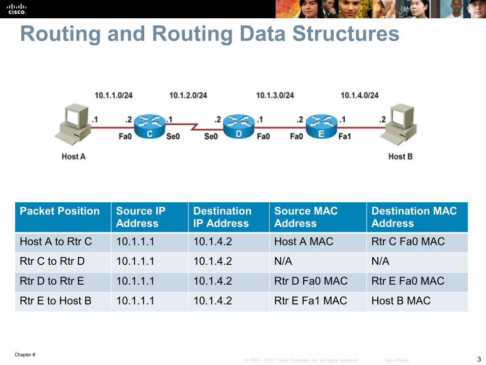
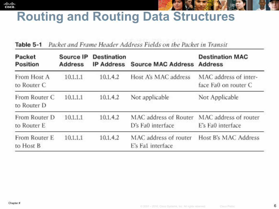
Routing and Routing Data Structures
Packet Position Source IP Address
Destination IP Address
Source MAC Address
Destination MAC Address
Host A to Rtr C 10.1.1.1 10.1.4.2 Host A MAC Rtr C Fa0 MAC
Rtr C to Rtr D 10.1.1.1 10.1.4.2 N/A N/A
Rtr D to Rtr E 10.1.1.1 10.1.4.2 Rtr D Fa0 MAC Rtr E Fa0 MAC
Rtr E to Host B 10.1.1.1 10.1.4.2 Rtr E Fa1 MAC Host B MAC
Chapter #4© 2007 – 2010, Cisco Systems, Inc. All rights reserved. Cisco Public
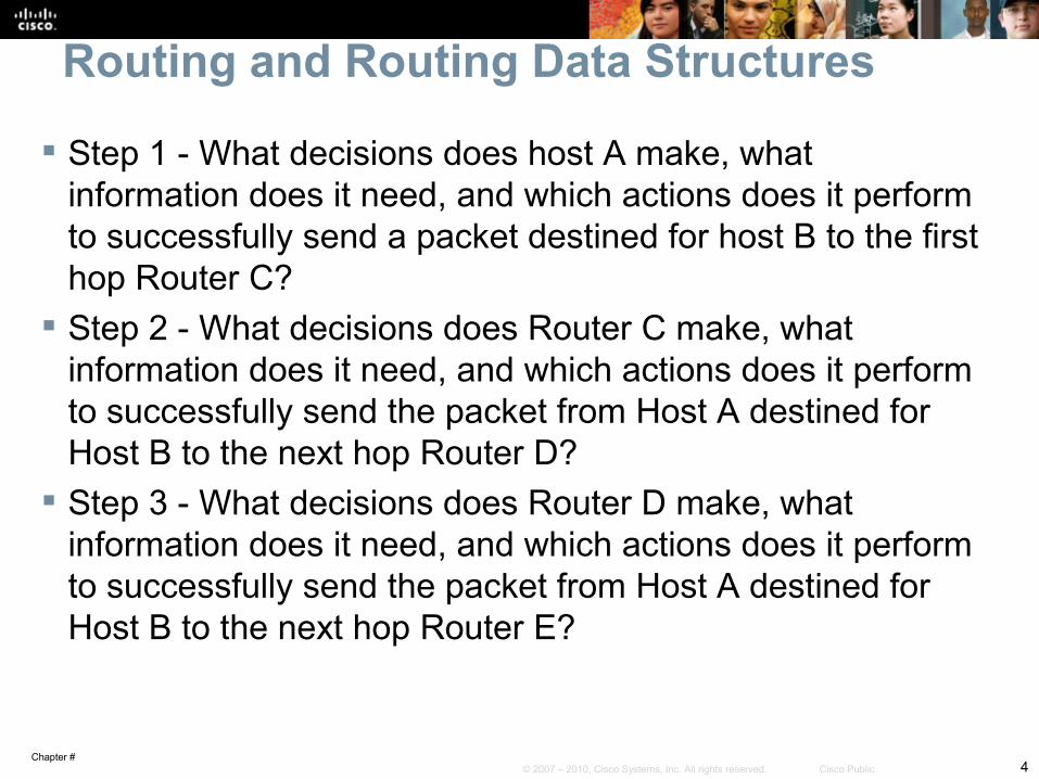
Routing and Routing Data Structures
Step 1 - What decisions does host A make, what information does it need, and which actions does it perform to successfully send a packet destined for host B to the first hop Router C?
Step 2 - What decisions does Router C make, what information does it need, and which actions does it perform to successfully send the packet from Host A destined for Host B to the next hop Router D?
Step 3 - What decisions does Router D make, what information does it need, and which actions does it perform to successfully send the packet from Host A destined for Host B to the next hop Router E?
Chapter #5© 2007 – 2010, Cisco Systems, Inc. All rights reserved. Cisco Public
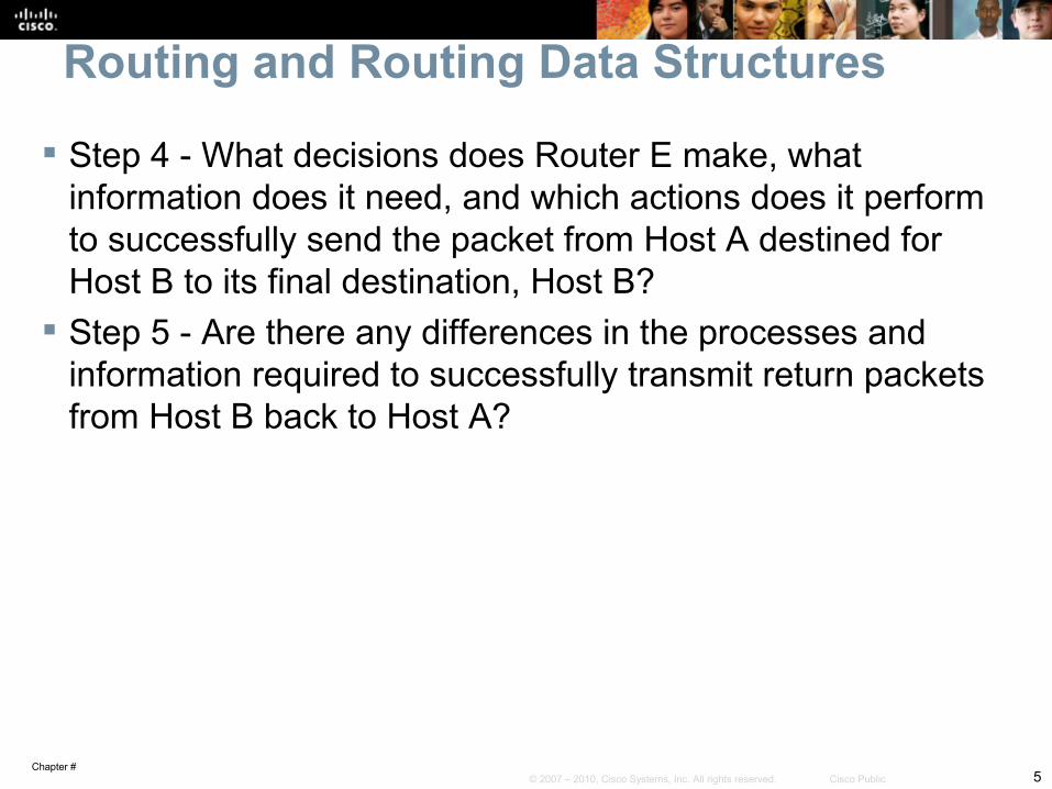
Routing and Routing Data Structures
Step 4 - What decisions does Router E make, what information does it need, and which actions does it perform to successfully send the packet from Host A destined for Host B to its final destination, Host B?
Step 5 - Are there any differences in the processes and information required to successfully transmit return packets from Host B back to Host A?
Chapter #6© 2007 – 2010, Cisco Systems, Inc. All rights reserved. Cisco Public
Routing and Routing Data Structures
Chapter #7© 2007 – 2010, Cisco Systems, Inc. All rights reserved. Cisco Public
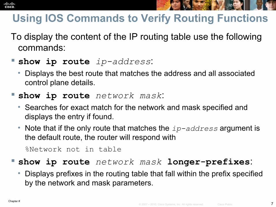
Using IOS Commands to Verify Routing FunctionsTo display the content of the IP routing table use the following
commands: show ip route ip-address:
• Displays the best route that matches the address and all associated control plane details.
show ip route network mask:• Searches for exact match for the network and mask specified and
displays the entry if found. • Note that if the only route that matches the ip-address argument is
the default route, the router will respond with%Network not in table
show ip route network mask longer-prefixes:• Displays prefixes in the routing table that fall within the prefix specified
by the network and mask parameters.
Chapter #8© 2007 – 2010, Cisco Systems, Inc. All rights reserved. Cisco Public
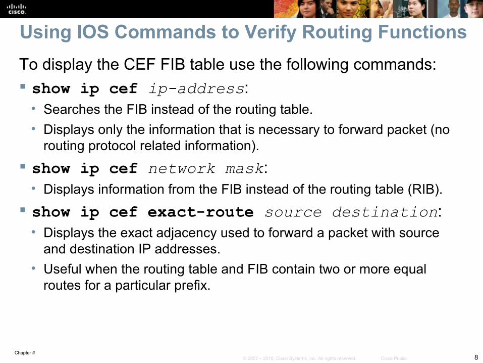
Using IOS Commands to Verify Routing FunctionsTo display the CEF FIB table use the following commands: show ip cef ip-address:
• Searches the FIB instead of the routing table.• Displays only the information that is necessary to forward packet (no
routing protocol related information). show ip cef network mask:
• Displays information from the FIB instead of the routing table (RIB). show ip cef exact-route source destination:
• Displays the exact adjacency used to forward a packet with source and destination IP addresses.
• Useful when the routing table and FIB contain two or more equal routes for a particular prefix.
Chapter #9© 2007 – 2010, Cisco Systems, Inc. All rights reserved. Cisco Public
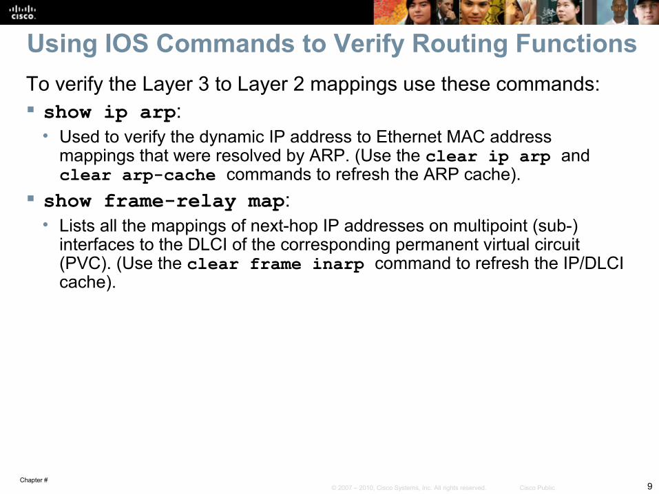
Using IOS Commands to Verify Routing FunctionsTo verify the Layer 3 to Layer 2 mappings use these commands: show ip arp:
• Used to verify the dynamic IP address to Ethernet MAC address mappings that were resolved by ARP. (Use the clear ip arp and clear arp-cache commands to refresh the ARP cache).
show frame-relay map:• Lists all the mappings of next-hop IP addresses on multipoint (sub-)
interfaces to the DLCI of the corresponding permanent virtual circuit (PVC). (Use the clear frame inarp command to refresh the IP/DLCI cache).
Chapter #10© 2007 – 2010, Cisco Systems, Inc. All rights reserved. Cisco Public
Troubleshooting EIGRP
Chapter #11© 2007 – 2010, Cisco Systems, Inc. All rights reserved. Cisco Public
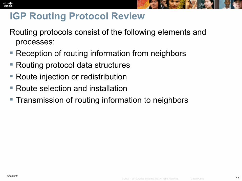
IGP Routing Protocol ReviewRouting protocols consist of the following elements and
processes: Reception of routing information from neighbors Routing protocol data structures Route injection or redistribution Route selection and installation Transmission of routing information to neighbors
Chapter #12© 2007 – 2010, Cisco Systems, Inc. All rights reserved. Cisco Public
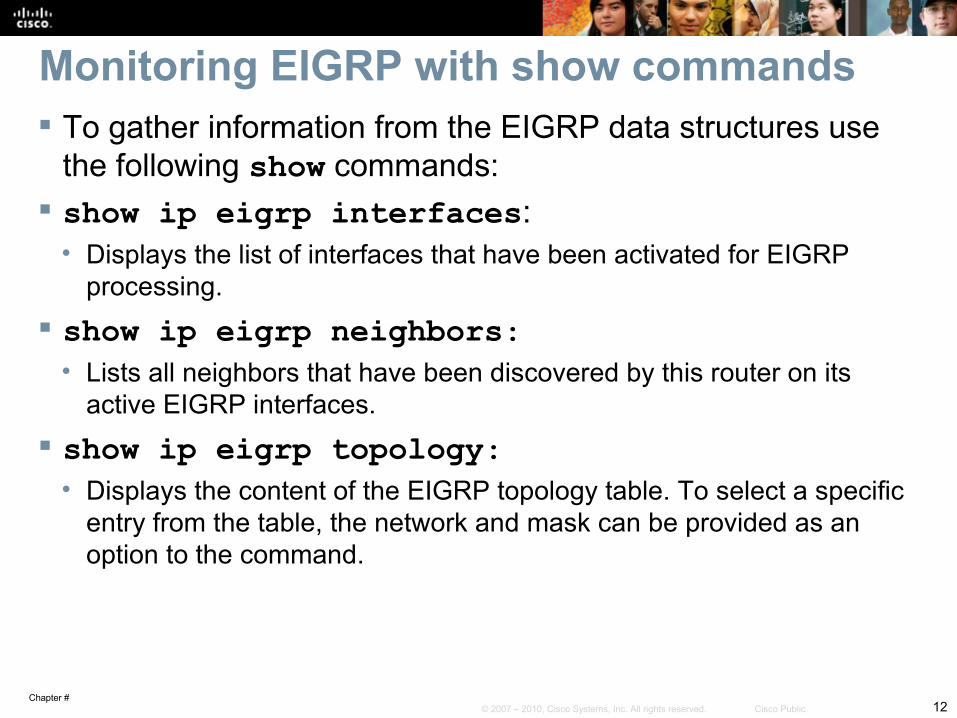
Monitoring EIGRP with show commands To gather information from the EIGRP data structures use
the following show commands: show ip eigrp interfaces:
• Displays the list of interfaces that have been activated for EIGRP processing.
show ip eigrp neighbors: • Lists all neighbors that have been discovered by this router on its
active EIGRP interfaces. show ip eigrp topology:
• Displays the content of the EIGRP topology table. To select a specific entry from the table, the network and mask can be provided as an option to the command.
Chapter #13© 2007 – 2010, Cisco Systems, Inc. All rights reserved. Cisco Public
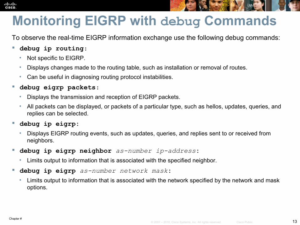
Monitoring EIGRP with debug CommandsTo observe the real-time EIGRP information exchange use the following debug commands: debug ip routing:
• Not specific to EIGRP.• Displays changes made to the routing table, such as installation or removal of routes.• Can be useful in diagnosing routing protocol instabilities.
debug eigrp packets:• Displays the transmission and reception of EIGRP packets.• All packets can be displayed, or packets of a particular type, such as hellos, updates, queries, and
replies can be selected.
debug ip eigrp:• Displays EIGRP routing events, such as updates, queries, and replies sent to or received from
neighbors.
debug ip eigrp neighbor as-number ip-address:• Limits output to information that is associated with the specified neighbor.
debug ip eigrp as-number network mask:• Limits output to information that is associated with the network specified by the network and mask
options.
Chapter #14© 2007 – 2010, Cisco Systems, Inc. All rights reserved. Cisco Public
EIGRP Troubleshooting Example:
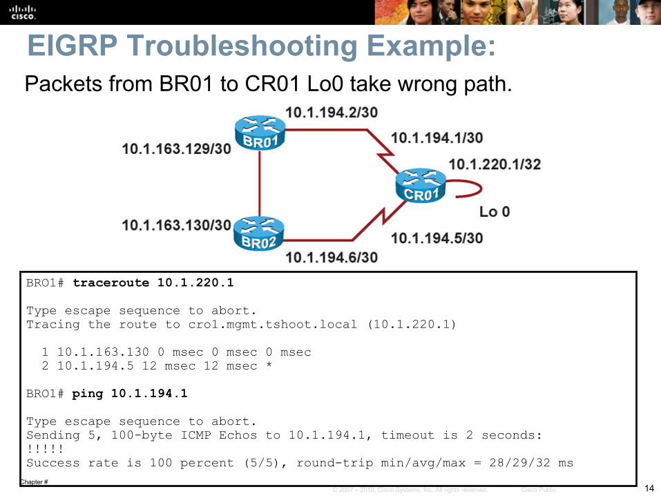
BRO1# traceroute 10.1.220.1 Type escape sequence to abort.Tracing the route to cro1.mgmt.tshoot.local (10.1.220.1) 1 10.1.163.130 0 msec 0 msec 0 msec 2 10.1.194.5 12 msec 12 msec *
BRO1# ping 10.1.194.1 Type escape sequence to abort.Sending 5, 100-byte ICMP Echos to 10.1.194.1, timeout is 2 seconds:!!!!!Success rate is 100 percent (5/5), round-trip min/avg/max = 28/29/32 ms
Packets from BR01 to CR01 Lo0 take wrong path.

Chapter #15© 2007 – 2010, Cisco Systems, Inc. All rights reserved. Cisco Public
EIGRP Troubleshooting Example – Cont.
BRO1# show ip eigrp topology 10.1.220.1 255.255.255.255IP-EIGRP (AS 1): Topology entry for 10.1.220.1/32 State is Passive, Query origin flag is 1, 1 Successor(s), FD is 40642560 Routing Descriptor Blocks: 10.1.163.130 (FastEthernet0/1.30), from 10.1.163.130, Send flag is 0x0 Composite metric is (40642560/40640000), Route is Internal Vector metric: Minimum bandwidth is 64 Kbit Total delay is 25100 microseconds Reliability is 255/255 Load is 1/255 Minimum MTU is 1500 Hop count is 2
BRO1# show ip eigrp neighborsIP-EIGRP neighbors for process 1H Address Interface Hold Uptime SRTT RTO Q Seq (sec) (ms) Cnt Num0 10.1.163.130 Fa0/1.30 12 00:09:56 4 200 0 585
EIGRP show commands indicate that there is only one BR01 topology entry for CR01 Lo0 and that BR01 and CR01 are not EIGRP neighbors.
Chapter #16© 2007 – 2010, Cisco Systems, Inc. All rights reserved. Cisco Public
EIGRP Troubleshooting Example – Cont.
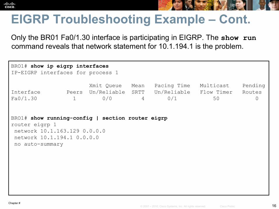
BRO1# show ip eigrp interfaces IP-EIGRP interfaces for process 1 Xmit Queue Mean Pacing Time Multicast PendingInterface Peers Un/Reliable SRTT Un/Reliable Flow Timer RoutesFa0/1.30 1 0/0 4 0/1 50 0
BRO1# show running-config | section router eigrprouter eigrp 1 network 10.1.163.129 0.0.0.0 network 10.1.194.1 0.0.0.0 no auto-summary
Only the BR01 Fa0/1.30 interface is participating in EIGRP. The show run command reveals that network statement for 10.1.194.1 is the problem.
Chapter #17© 2007 – 2010, Cisco Systems, Inc. All rights reserved. Cisco Public
EIGRP Troubleshooting Example – Cont.
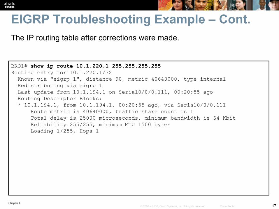
BRO1# show ip route 10.1.220.1 255.255.255.255Routing entry for 10.1.220.1/32 Known via "eigrp 1", distance 90, metric 40640000, type internal Redistributing via eigrp 1 Last update from 10.1.194.1 on Serial0/0/0.111, 00:20:55 ago Routing Descriptor Blocks: * 10.1.194.1, from 10.1.194.1, 00:20:55 ago, via Serial0/0/0.111 Route metric is 40640000, traffic share count is 1 Total delay is 25000 microseconds, minimum bandwidth is 64 Kbit Reliability 255/255, minimum MTU 1500 bytes Loading 1/255, Hops 1
The IP routing table after corrections were made.
Chapter #18© 2007 – 2010, Cisco Systems, Inc. All rights reserved. Cisco Public
EIGRP Troubleshooting Example – Cont.
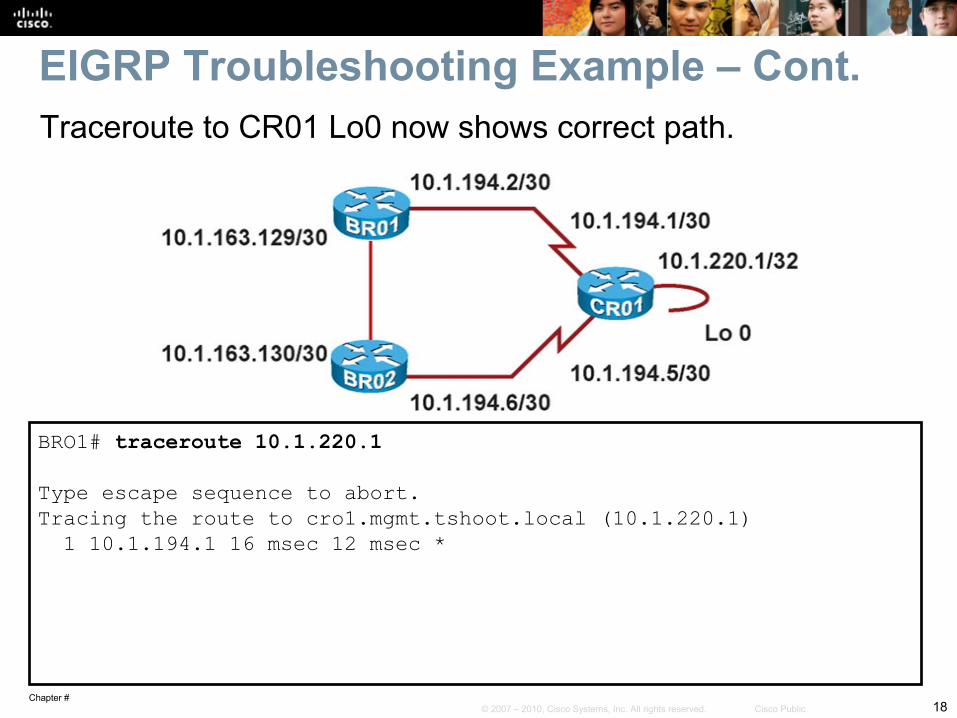
BRO1# traceroute 10.1.220.1 Type escape sequence to abort.Tracing the route to cro1.mgmt.tshoot.local (10.1.220.1) 1 10.1.194.1 16 msec 12 msec *
Traceroute to CR01 Lo0 now shows correct path.
Chapter #19© 2007 – 2010, Cisco Systems, Inc. All rights reserved. Cisco Public
Troubleshooting OSPF
Chapter #20© 2007 – 2010, Cisco Systems, Inc. All rights reserved. Cisco Public
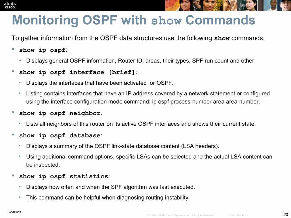
To gather information from the OSPF data structures use the following show commands:
show ip ospf:• Displays general OSPF information, Router ID, areas, their types, SPF run count and other
show ip ospf interface [brief]:• Displays the interfaces that have been activated for OSPF.
• Listing contains interfaces that have an IP address covered by a network statement or configured using the interface configuration mode command: ip ospf process-number area area-number.
show ip ospf neighbor:• Lists all neighbors of this router on its active OSPF interfaces and shows their current state.
show ip ospf database:• Displays a summary of the OSPF link-state database content (LSA headers).
• Using additional command options, specific LSAs can be selected and the actual LSA content can be inspected.
show ip ospf statistics:• Displays how often and when the SPF algorithm was last executed.
• This command can be helpful when diagnosing routing instability.
Monitoring OSPF with show Commands
Chapter #21© 2007 – 2010, Cisco Systems, Inc. All rights reserved. Cisco Public
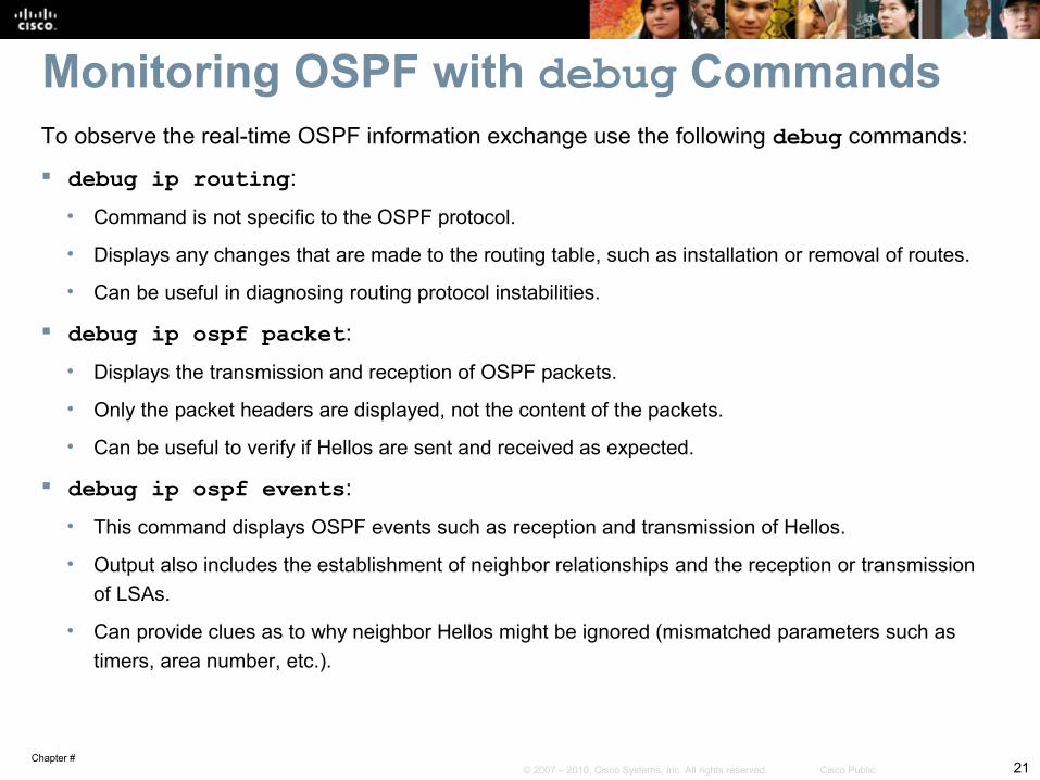
To observe the real-time OSPF information exchange use the following debug commands:
debug ip routing:• Command is not specific to the OSPF protocol.
• Displays any changes that are made to the routing table, such as installation or removal of routes.
• Can be useful in diagnosing routing protocol instabilities.
debug ip ospf packet:• Displays the transmission and reception of OSPF packets.
• Only the packet headers are displayed, not the content of the packets.
• Can be useful to verify if Hellos are sent and received as expected.
debug ip ospf events:• This command displays OSPF events such as reception and transmission of Hellos.
• Output also includes the establishment of neighbor relationships and the reception or transmission of LSAs.
• Can provide clues as to why neighbor Hellos might be ignored (mismatched parameters such as timers, area number, etc.).
Monitoring OSPF with debug Commands
Chapter #22© 2007 – 2010, Cisco Systems, Inc. All rights reserved. Cisco Public
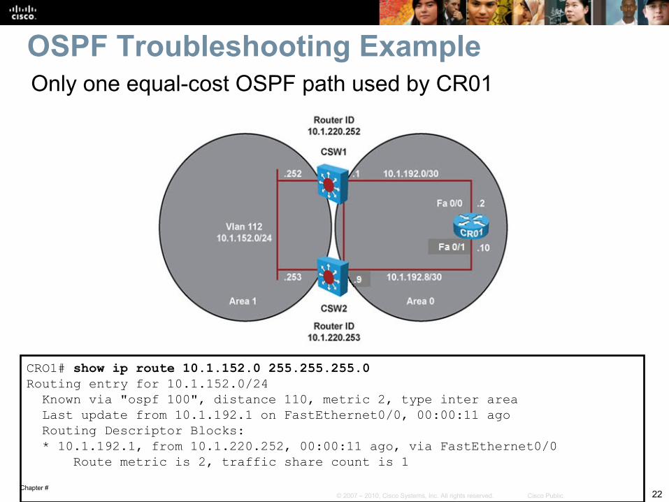
CRO1# show ip route 10.1.152.0 255.255.255.0Routing entry for 10.1.152.0/24 Known via "ospf 100", distance 110, metric 2, type inter area Last update from 10.1.192.1 on FastEthernet0/0, 00:00:11 ago Routing Descriptor Blocks: * 10.1.192.1, from 10.1.220.252, 00:00:11 ago, via FastEthernet0/0 Route metric is 2, traffic share count is 1
OSPF Troubleshooting ExampleOnly one equal-cost OSPF path used by CR01
Chapter #23© 2007 – 2010, Cisco Systems, Inc. All rights reserved. Cisco Public
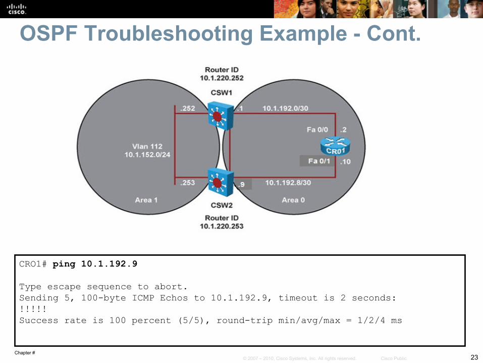
OSPF Troubleshooting Example - Cont.
CRO1# ping 10.1.192.9 Type escape sequence to abort.Sending 5, 100-byte ICMP Echos to 10.1.192.9, timeout is 2 seconds:!!!!!Success rate is 100 percent (5/5), round-trip min/avg/max = 1/2/4 ms
Chapter #24© 2007 – 2010, Cisco Systems, Inc. All rights reserved. Cisco Public
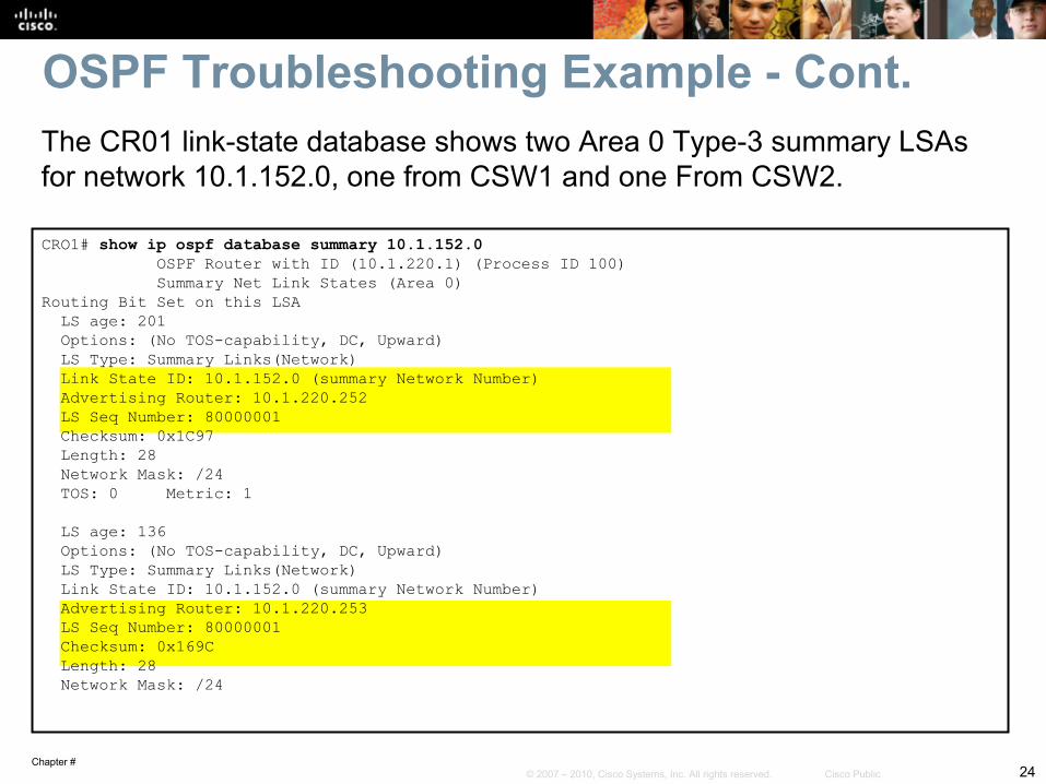
CRO1# show ip ospf database summary 10.1.152.0 OSPF Router with ID (10.1.220.1) (Process ID 100) Summary Net Link States (Area 0)Routing Bit Set on this LSA LS age: 201 Options: (No TOS-capability, DC, Upward) LS Type: Summary Links(Network) Link State ID: 10.1.152.0 (summary Network Number) Advertising Router: 10.1.220.252 LS Seq Number: 80000001 Checksum: 0x1C97 Length: 28 Network Mask: /24 TOS: 0 Metric: 1 LS age: 136 Options: (No TOS-capability, DC, Upward) LS Type: Summary Links(Network) Link State ID: 10.1.152.0 (summary Network Number) Advertising Router: 10.1.220.253 LS Seq Number: 80000001 Checksum: 0x169C Length: 28 Network Mask: /24
The CR01 link-state database shows two Area 0 Type-3 summary LSAs for network 10.1.152.0, one from CSW1 and one From CSW2.
OSPF Troubleshooting Example - Cont.

Chapter #25© 2007 – 2010, Cisco Systems, Inc. All rights reserved. Cisco Public
OSPF Troubleshooting Example - Cont.
CRO1# show ip ospf neighbor Neighbor ID Pri State Dead Time Address Interface10.1.220.252 1 FULL/DR 00:00:33 10.1.192.1 FastEthernet0/0
Chapter #26© 2007 – 2010, Cisco Systems, Inc. All rights reserved. Cisco Public
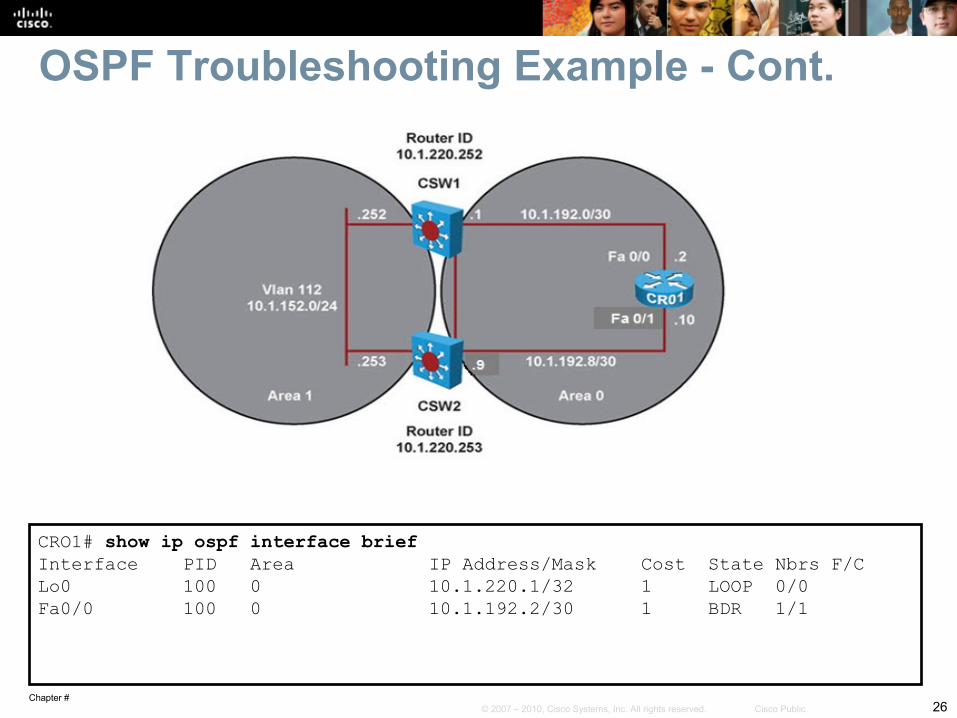
OSPF Troubleshooting Example - Cont.
CRO1# show ip ospf interface briefInterface PID Area IP Address/Mask Cost State Nbrs F/CLo0 100 0 10.1.220.1/32 1 LOOP 0/0Fa0/0 100 0 10.1.192.2/30 1 BDR 1/1

Chapter #27© 2007 – 2010, Cisco Systems, Inc. All rights reserved. Cisco Public
OSPF Troubleshooting Example - Cont.
CRO1# show running-config | section router ospfrouter ospf 100 log-adjacency-changes network 10.1.192.2 0.0.0.0 area 0 network 10.1.192.9 0.0.0.0 area 0 network 10.1.220.1 0.0.0.0 area 0
Chapter #28© 2007 – 2010, Cisco Systems, Inc. All rights reserved. Cisco Public
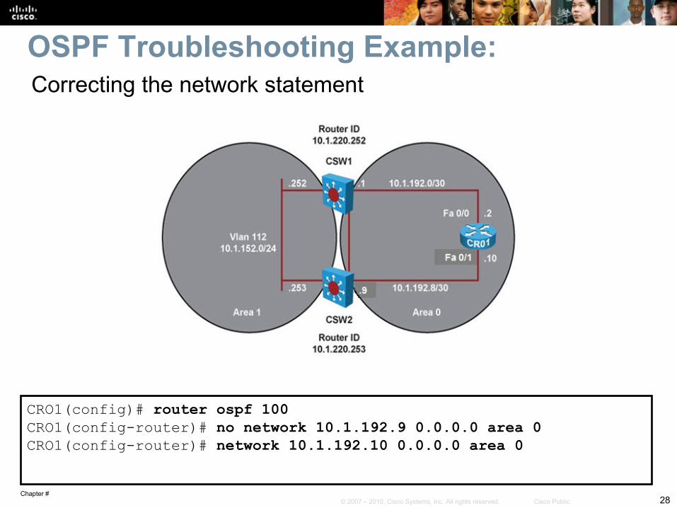
CRO1(config)# router ospf 100CRO1(config-router)# no network 10.1.192.9 0.0.0.0 area 0CRO1(config-router)# network 10.1.192.10 0.0.0.0 area 0
OSPF Troubleshooting Example:Correcting the network statement
Chapter #29© 2007 – 2010, Cisco Systems, Inc. All rights reserved. Cisco Public
OSPF Troubleshooting Example - Cont.
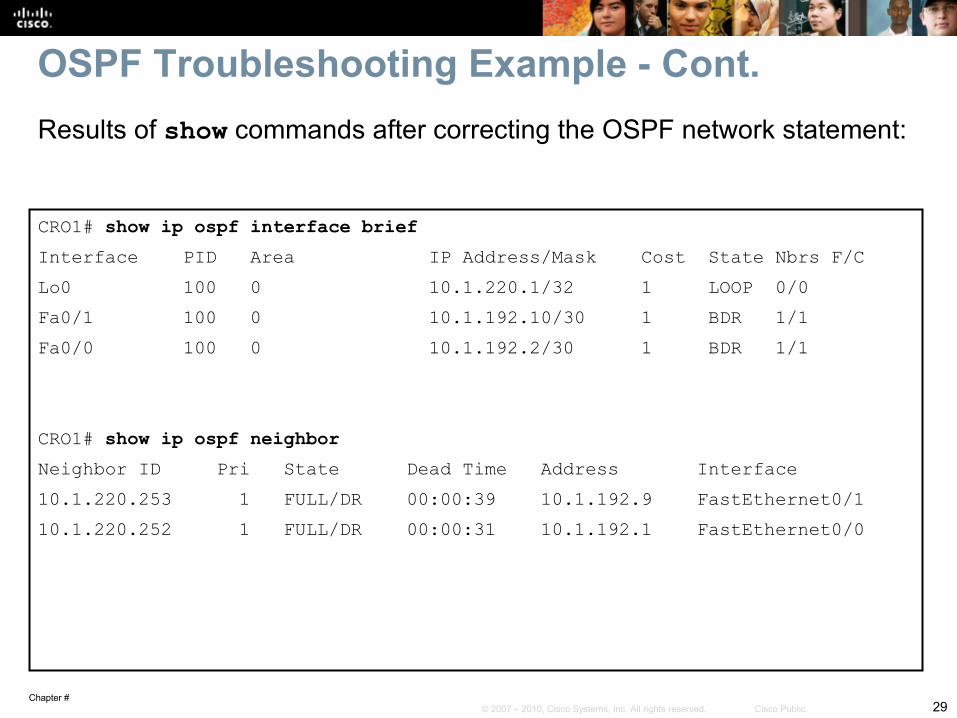
CRO1# show ip ospf interface briefInterface PID Area IP Address/Mask Cost State Nbrs F/CLo0 100 0 10.1.220.1/32 1 LOOP 0/0Fa0/1 100 0 10.1.192.10/30 1 BDR 1/1Fa0/0 100 0 10.1.192.2/30 1 BDR 1/1
CRO1# show ip ospf neighborNeighbor ID Pri State Dead Time Address Interface10.1.220.253 1 FULL/DR 00:00:39 10.1.192.9 FastEthernet0/110.1.220.252 1 FULL/DR 00:00:31 10.1.192.1 FastEthernet0/0
Results of show commands after correcting the OSPF network statement:
Chapter #30© 2007 – 2010, Cisco Systems, Inc. All rights reserved. Cisco Public
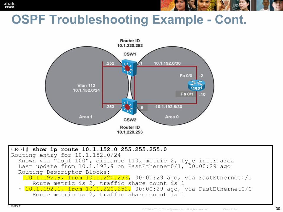
OSPF Troubleshooting Example - Cont.
CRO1# show ip route 10.1.152.0 255.255.255.0Routing entry for 10.1.152.0/24 Known via "ospf 100", distance 110, metric 2, type inter area Last update from 10.1.192.9 on FastEthernet0/1, 00:00:29 ago Routing Descriptor Blocks: 10.1.192.9, from 10.1.220.253, 00:00:29 ago, via FastEthernet0/1 Route metric is 2, traffic share count is 1 * 10.1.192.1, from 10.1.220.252, 00:00:29 ago, via FastEthernet0/0 Route metric is 2, traffic share count is 1
Chapter #31© 2007 – 2010, Cisco Systems, Inc. All rights reserved. Cisco Public
Troubleshooting Route Redistribution
Chapter #32© 2007 – 2010, Cisco Systems, Inc. All rights reserved. Cisco Public
Route Redistribution Review Ideally, no more than one interior (intra-AS) routing protocol is
used within an organization. Organizational requirements (mergers, migrations) might dictate
the use of multiple routing protocols. Route redistribution between the different routing protocols may
be necessary for IP connectivity between the different parts of the network.
Route redistribution adds an extra layer of complexity to a routed network.
It is important to understand the interactions between multiple routing protocols.
A network support engineer must be able to diagnose and resolve problems such as suboptimal routing and routing feedback that can occur when route redistribution is implemented.
Chapter #33© 2007 – 2010, Cisco Systems, Inc. All rights reserved. Cisco Public
Troubleshooting IP connectivity problems caused by redistribution involves the following elements:
Troubleshooting the source routing protocol:• Routes can only be redistributed if they are present in the routing table of
the redistributing router.• Confirm that the expected routes are learned on the redistributing router
via the source protocol.
Troubleshooting route selection and installation:• With bidirectional redistribution between routing protocols routing loops
can be created.• Suboptimal routing can occur causing routing instability requiring
diagnosis.• Changing the administrative distance or filtering routes to influence the
route selection and installation process can often solve the problem.
Verifying and Troubleshooting Route Propagation
Chapter #34© 2007 – 2010, Cisco Systems, Inc. All rights reserved. Cisco Public
Troubleshooting IP connectivity problems caused by redistribution involves the following elements:
Troubleshooting the redistribution process:• If routes are in the routing table of the redistributing router, but not advertised by
the redistributing protocol, verify the configuration of the redistribution process.• Bad seed metrics, route filtering, or misconfigured routing protocol process or
autonomous system numbers are common causes for the redistribution process to fail.
Troubleshooting the destination routing protocol:• If the routing information is propagated using a protocol’s routing update
mechanisms, but not properly distributed to all routers in the destination routing domain, troubleshoot the routing exchange mechanisms for the destination protocol.
• Each routing protocol has its own methods of exchanging routing information, including external routing information.
• Determine if external routes are handled differently than internal routes. For example, OSPF external routes do not propagate into stub areas.
Verifying and Troubleshooting Route Propagation – Cont.
Chapter #35© 2007 – 2010, Cisco Systems, Inc. All rights reserved. Cisco Public
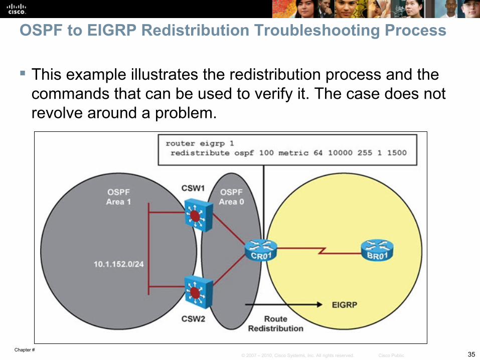
OSPF to EIGRP Redistribution Troubleshooting Process
This example illustrates the redistribution process and the commands that can be used to verify it. The case does not revolve around a problem.
Chapter #36© 2007 – 2010, Cisco Systems, Inc. All rights reserved. Cisco Public
OSPF to EIGRP Redistribution Troubleshooting Process – Cont.
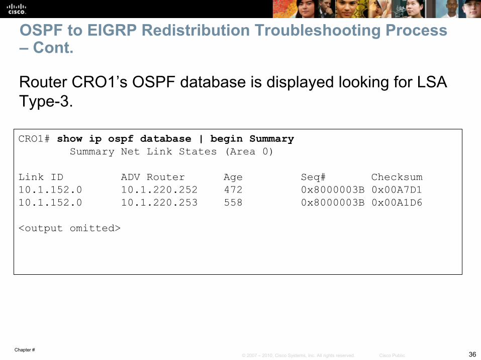
Router CRO1’s OSPF database is displayed looking for LSA Type-3.
CRO1# show ip ospf database | begin Summary Summary Net Link States (Area 0) Link ID ADV Router Age Seq# Checksum10.1.152.0 10.1.220.252 472 0x8000003B 0x00A7D110.1.152.0 10.1.220.253 558 0x8000003B 0x00A1D6
<output omitted>
Chapter #37© 2007 – 2010, Cisco Systems, Inc. All rights reserved. Cisco Public
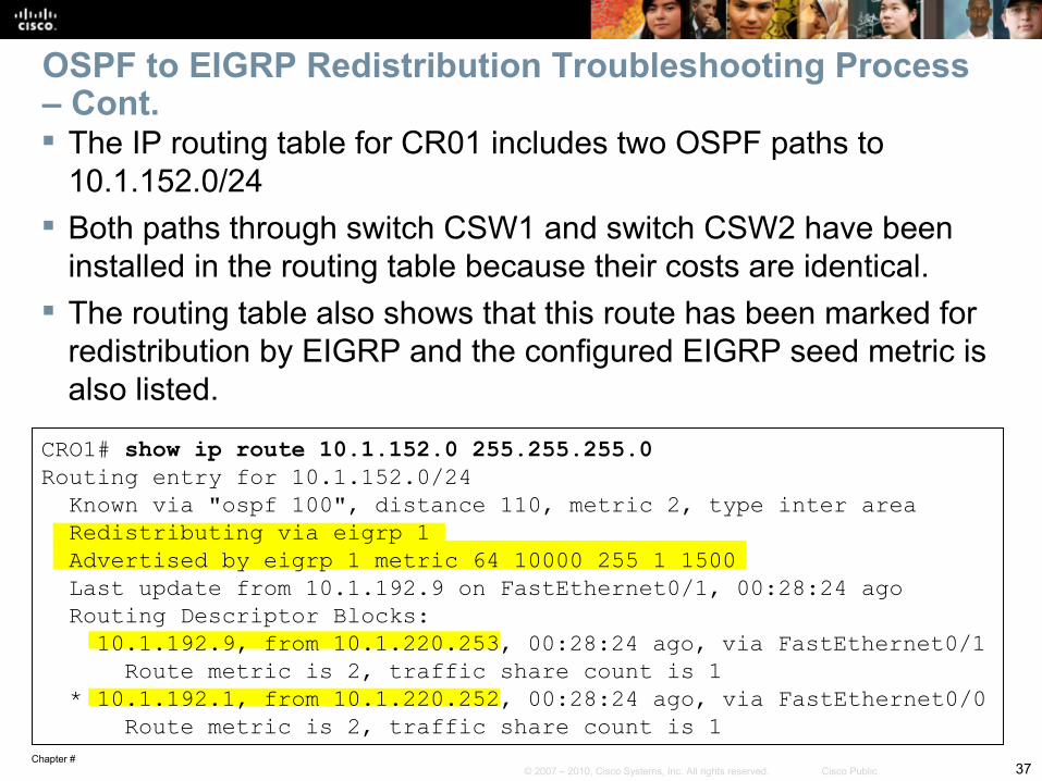
OSPF to EIGRP Redistribution Troubleshooting Process – Cont. The IP routing table for CR01 includes two OSPF paths to
10.1.152.0/24 Both paths through switch CSW1 and switch CSW2 have been
installed in the routing table because their costs are identical. The routing table also shows that this route has been marked for
redistribution by EIGRP and the configured EIGRP seed metric is also listed.
CRO1# show ip route 10.1.152.0 255.255.255.0Routing entry for 10.1.152.0/24 Known via "ospf 100", distance 110, metric 2, type inter area Redistributing via eigrp 1 Advertised by eigrp 1 metric 64 10000 255 1 1500 Last update from 10.1.192.9 on FastEthernet0/1, 00:28:24 ago Routing Descriptor Blocks: 10.1.192.9, from 10.1.220.253, 00:28:24 ago, via FastEthernet0/1 Route metric is 2, traffic share count is 1 * 10.1.192.1, from 10.1.220.252, 00:28:24 ago, via FastEthernet0/0 Route metric is 2, traffic share count is 1
Chapter #38© 2007 – 2010, Cisco Systems, Inc. All rights reserved. Cisco Public
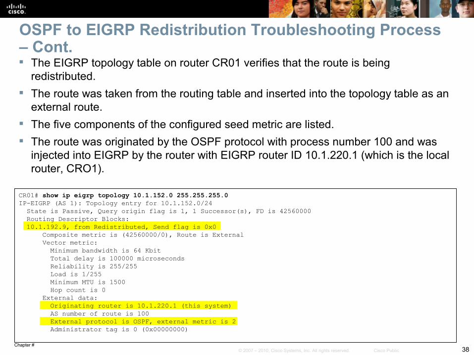
OSPF to EIGRP Redistribution Troubleshooting Process – Cont. The EIGRP topology table on router CR01 verifies that the route is being
redistributed. The route was taken from the routing table and inserted into the topology table as an
external route. The five components of the configured seed metric are listed. The route was originated by the OSPF protocol with process number 100 and was
injected into EIGRP by the router with EIGRP router ID 10.1.220.1 (which is the local router, CRO1).
CR01# show ip eigrp topology 10.1.152.0 255.255.255.0IP-EIGRP (AS 1): Topology entry for 10.1.152.0/24 State is Passive, Query origin flag is 1, 1 Successor(s), FD is 42560000 Routing Descriptor Blocks: 10.1.192.9, from Redistributed, Send flag is 0x0 Composite metric is (42560000/0), Route is External Vector metric: Minimum bandwidth is 64 Kbit Total delay is 100000 microseconds Reliability is 255/255 Load is 1/255 Minimum MTU is 1500 Hop count is 0 External data: Originating router is 10.1.220.1 (this system) AS number of route is 100 External protocol is OSPF, external metric is 2 Administrator tag is 0 (0x00000000)
Chapter #39© 2007 – 2010, Cisco Systems, Inc. All rights reserved. Cisco Public
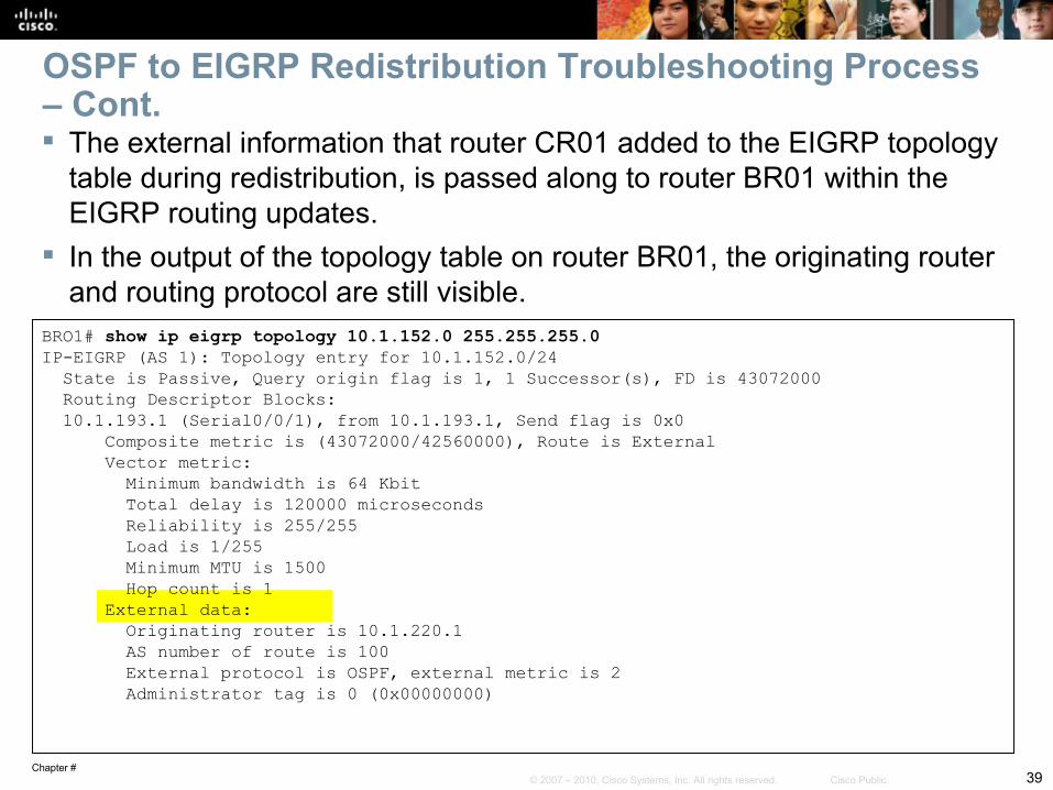
OSPF to EIGRP Redistribution Troubleshooting Process – Cont. The external information that router CR01 added to the EIGRP topology
table during redistribution, is passed along to router BR01 within the EIGRP routing updates.
In the output of the topology table on router BR01, the originating router and routing protocol are still visible.
BRO1# show ip eigrp topology 10.1.152.0 255.255.255.0IP-EIGRP (AS 1): Topology entry for 10.1.152.0/24 State is Passive, Query origin flag is 1, 1 Successor(s), FD is 43072000 Routing Descriptor Blocks: 10.1.193.1 (Serial0/0/1), from 10.1.193.1, Send flag is 0x0 Composite metric is (43072000/42560000), Route is External Vector metric: Minimum bandwidth is 64 Kbit Total delay is 120000 microseconds Reliability is 255/255 Load is 1/255 Minimum MTU is 1500 Hop count is 1 External data: Originating router is 10.1.220.1 AS number of route is 100 External protocol is OSPF, external metric is 2 Administrator tag is 0 (0x00000000)
Chapter #40© 2007 – 2010, Cisco Systems, Inc. All rights reserved. Cisco Public
OSPF to EIGRP Redistribution Troubleshooting Process – Cont.
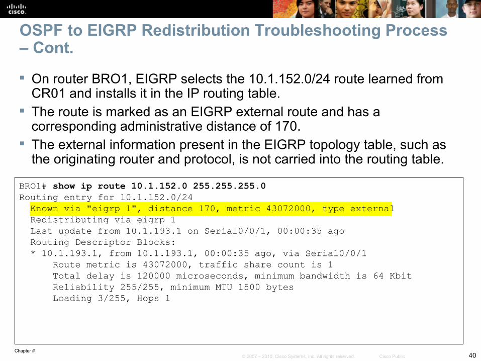
On router BRO1, EIGRP selects the 10.1.152.0/24 route learned from CR01 and installs it in the IP routing table.
The route is marked as an EIGRP external route and has a corresponding administrative distance of 170.
The external information present in the EIGRP topology table, such as the originating router and protocol, is not carried into the routing table.
BRO1# show ip route 10.1.152.0 255.255.255.0Routing entry for 10.1.152.0/24 Known via "eigrp 1", distance 170, metric 43072000, type external Redistributing via eigrp 1 Last update from 10.1.193.1 on Serial0/0/1, 00:00:35 ago Routing Descriptor Blocks: * 10.1.193.1, from 10.1.193.1, 00:00:35 ago, via Serial0/0/1 Route metric is 43072000, traffic share count is 1 Total delay is 120000 microseconds, minimum bandwidth is 64 Kbit Reliability 255/255, minimum MTU 1500 bytes Loading 3/255, Hops 1

Chapter #41© 2007 – 2010, Cisco Systems, Inc. All rights reserved. Cisco Public
Troubleshooting BGP
Chapter #42© 2007 – 2010, Cisco Systems, Inc. All rights reserved. Cisco Public
BGP is classified as an EGP or an inter-autonomous-system (inter-AS) routing protocol.
Plays a different role in enterprise networks as compared to IGPs, such as EIGRP or OSPF.
Not used to find the best paths within the enterprise network. Exchanges routing information with external networks (other
autonomous systems), such as ISPs. Used to implement routing policies to control the flow of traffic to
and from external networks.
BGP Overview
Chapter #43© 2007 – 2010, Cisco Systems, Inc. All rights reserved. Cisco Public
Reception of routing information from neighbors:• Neighbors need not be directly connected.• They are manually configured, not discovered through a hello
protocol.• A TCP session is established between neighbors to exchange routing
information and the session can span multiple router hops if necessary.
• Two BGP routers that exchange information are commonly referred to as peers.
• Cisco IOS command outputs use the term neighbor. Routing protocol data structures:
• Neighbor table: Keeps track of the state of configured neighbors.• BGP table: Stores all the prefixes, including those received from the
neighbors.
BGP Route Processing and Data Structures
Chapter #44© 2007 – 2010, Cisco Systems, Inc. All rights reserved. Cisco Public
Route injection or redistribution: BGP does not automatically inject any routes into the BGP table. Routes learned from neighbors are placed in the BGP table and
can be advertised out to other BGP neighbors. Routes learned from internal (IBGP) neighbors are subject to the
synchronization rule, unless synchronization is off. Methods to inject prefixes into the BGP table and advertise them
to BGP neighbors:1. The prefixes must be specifically configured under the BGP routing
process (using the network statement)2. The prefixes must be redistributed into BGP (from connected, static, or
another interior routing protocol). In both cases, a prefix needs to be present in the IP routing table
before it can be advertised to BGP neighbors.
BGP Route Processing and Data Structures – Cont.
Chapter #45© 2007 – 2010, Cisco Systems, Inc. All rights reserved. Cisco Public
Neighbor table: Lists all neighbors that have been configured on a router. Stores information such as:
• Configured autonomous system (AS) number of the neighbor• Whether the neighbor is an internal or an external peer• The state of the session• Capabilities of the peer• How long the neighbor has been up/down for (uptime)• How many prefixes were exchanged with the neighbor.
BGP Route Processing and Data Structures – Cont.
Chapter #46© 2007 – 2010, Cisco Systems, Inc. All rights reserved. Cisco Public
BGP table:Stores BGP attributes that are associated with each route, such as:
• Next hop
• AS path
• Local preference
• Origin
• Multi-exit discriminator (MED) or metric
• Origin code
• Community attributes.
BGP Route Processing and Data Structures – Cont.
Chapter #47© 2007 – 2010, Cisco Systems, Inc. All rights reserved. Cisco Public
To gather information from the BGP data structures use the following show commands:
show ip bgp:• Displays the content of the BGP table.• To select a specific entry from the table, provide the network and
mask of the selected prefix as an option.• Useful during troubleshooting to verify:
• What paths are present• What their attributes are• Why certain paths are selected as best.
• Does not reveal all of the attributes of the BGP paths. show ip bgp prefix netmask:
• Display all of the attributes for a specific BGP prefix.
Monitoring BGP with show Commands – Cont.
Chapter #48© 2007 – 2010, Cisco Systems, Inc. All rights reserved. Cisco Public
debug ip bgp:• Does not display the content of the BGP updates.
debug ip bgp updates:• Output can be limited to a specific neighbor and specific prefixes by
use of extra options.
• Issuing the command debug ip bgp ip-address updates access-list limits the output of the command to only updates received from or sent to the neighbor specified by the ip-address option and only for those networks that match the access list specified by the access-list option.
Monitoring BGP with debug Commands
Chapter #49© 2007 – 2010, Cisco Systems, Inc. All rights reserved. Cisco Public
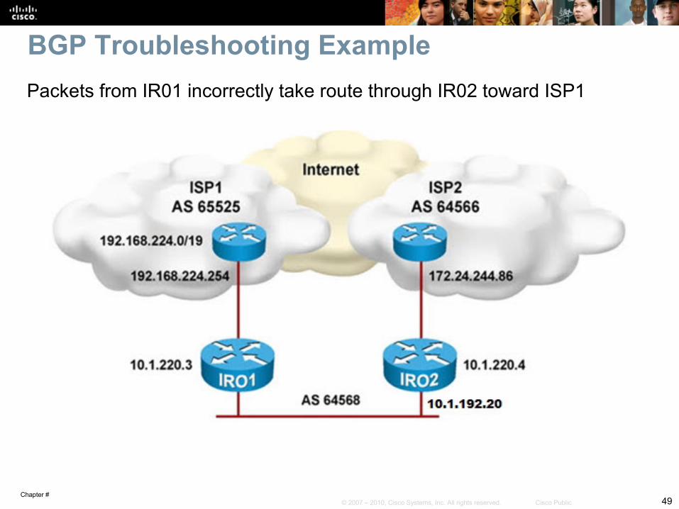
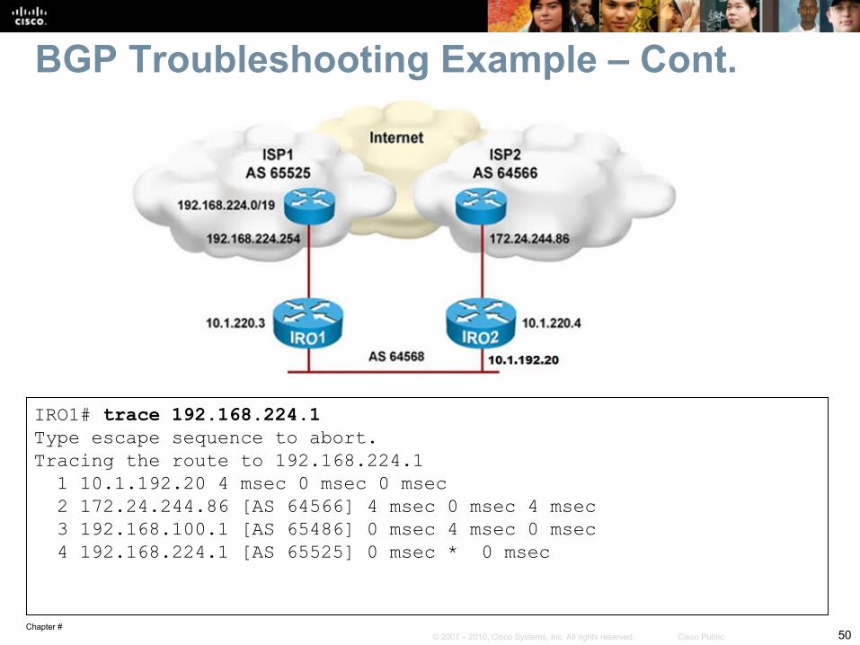
Packets from IR01 incorrectly take route through IR02 toward ISP1
BGP Troubleshooting Example
Chapter #50© 2007 – 2010, Cisco Systems, Inc. All rights reserved. Cisco Public
BGP Troubleshooting Example – Cont.
IRO1# trace 192.168.224.1Type escape sequence to abort.Tracing the route to 192.168.224.1 1 10.1.192.20 4 msec 0 msec 0 msec 2 172.24.244.86 [AS 64566] 4 msec 0 msec 4 msec 3 192.168.100.1 [AS 65486] 0 msec 4 msec 0 msec 4 192.168.224.1 [AS 65525] 0 msec * 0 msec
Chapter #51© 2007 – 2010, Cisco Systems, Inc. All rights reserved. Cisco Public
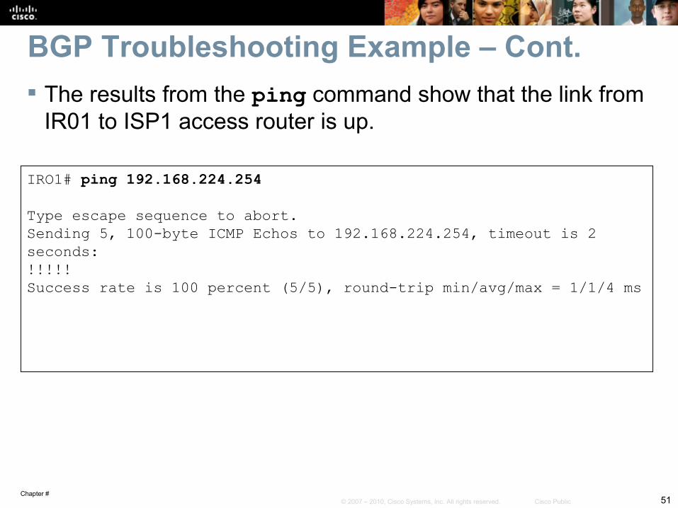
BGP Troubleshooting Example – Cont. The results from the ping command show that the link from
IR01 to ISP1 access router is up.
IRO1# ping 192.168.224.254 Type escape sequence to abort.Sending 5, 100-byte ICMP Echos to 192.168.224.254, timeout is 2 seconds:!!!!!Success rate is 100 percent (5/5), round-trip min/avg/max = 1/1/4 ms
Chapter #52© 2007 – 2010, Cisco Systems, Inc. All rights reserved. Cisco Public
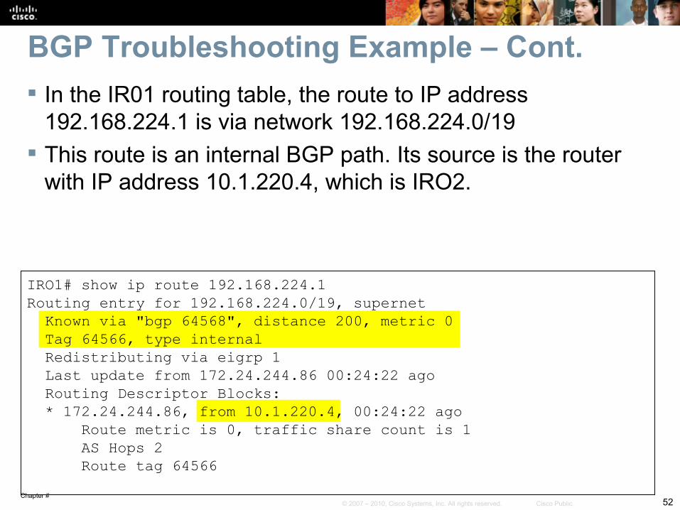
BGP Troubleshooting Example – Cont. In the IR01 routing table, the route to IP address
192.168.224.1 is via network 192.168.224.0/19 This route is an internal BGP path. Its source is the router
with IP address 10.1.220.4, which is IRO2.
IRO1# show ip route 192.168.224.1Routing entry for 192.168.224.0/19, supernet Known via "bgp 64568", distance 200, metric 0 Tag 64566, type internal Redistributing via eigrp 1 Last update from 172.24.244.86 00:24:22 ago Routing Descriptor Blocks: * 172.24.244.86, from 10.1.220.4, 00:24:22 ago Route metric is 0, traffic share count is 1 AS Hops 2 Route tag 64566
Chapter #53© 2007 – 2010, Cisco Systems, Inc. All rights reserved. Cisco Public
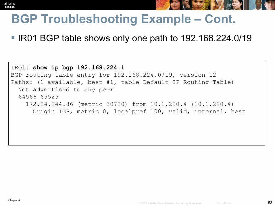
BGP Troubleshooting Example – Cont. IR01 BGP table shows only one path to 192.168.224.0/19
IRO1# show ip bgp 192.168.224.1BGP routing table entry for 192.168.224.0/19, version 12Paths: (1 available, best #1, table Default-IP-Routing-Table) Not advertised to any peer 64566 65525 172.24.244.86 (metric 30720) from 10.1.220.4 (10.1.220.4) Origin IGP, metric 0, localpref 100, valid, internal, best
Chapter #54© 2007 – 2010, Cisco Systems, Inc. All rights reserved. Cisco Public
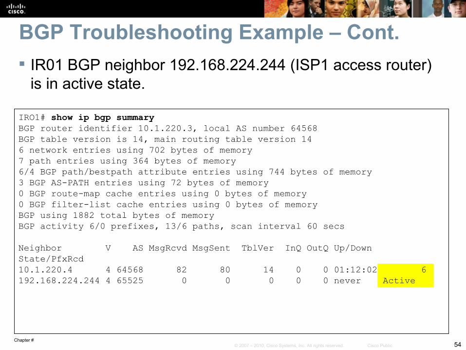
BGP Troubleshooting Example – Cont. IR01 BGP neighbor 192.168.224.244 (ISP1 access router)
is in active state.
IRO1# show ip bgp summaryBGP router identifier 10.1.220.3, local AS number 64568BGP table version is 14, main routing table version 146 network entries using 702 bytes of memory7 path entries using 364 bytes of memory6/4 BGP path/bestpath attribute entries using 744 bytes of memory3 BGP AS-PATH entries using 72 bytes of memory0 BGP route-map cache entries using 0 bytes of memory0 BGP filter-list cache entries using 0 bytes of memoryBGP using 1882 total bytes of memoryBGP activity 6/0 prefixes, 13/6 paths, scan interval 60 secs Neighbor V AS MsgRcvd MsgSent TblVer InQ OutQ Up/Down State/PfxRcd10.1.220.4 4 64568 82 80 14 0 0 01:12:02 6192.168.224.244 4 65525 0 0 0 0 0 never Active
Chapter #55© 2007 – 2010, Cisco Systems, Inc. All rights reserved. Cisco Public
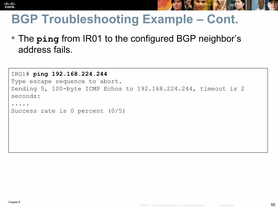
BGP Troubleshooting Example – Cont. The ping from IR01 to the configured BGP neighbor’s
address fails.
IRO1# ping 192.168.224.244 Type escape sequence to abort.Sending 5, 100-byte ICMP Echos to 192.168.224.244, timeout is 2 seconds:.....Success rate is 0 percent (0/5)
Chapter #56© 2007 – 2010, Cisco Systems, Inc. All rights reserved. Cisco Public
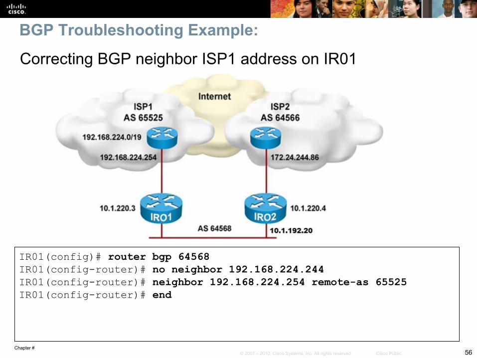
BGP Troubleshooting Example:
IR01(config)# router bgp 64568IR01(config-router)# no neighbor 192.168.224.244IR01(config-router)# neighbor 192.168.224.254 remote-as 65525IR01(config-router)# end
Correcting BGP neighbor ISP1 address on IR01
Chapter #57© 2007 – 2010, Cisco Systems, Inc. All rights reserved. Cisco Public
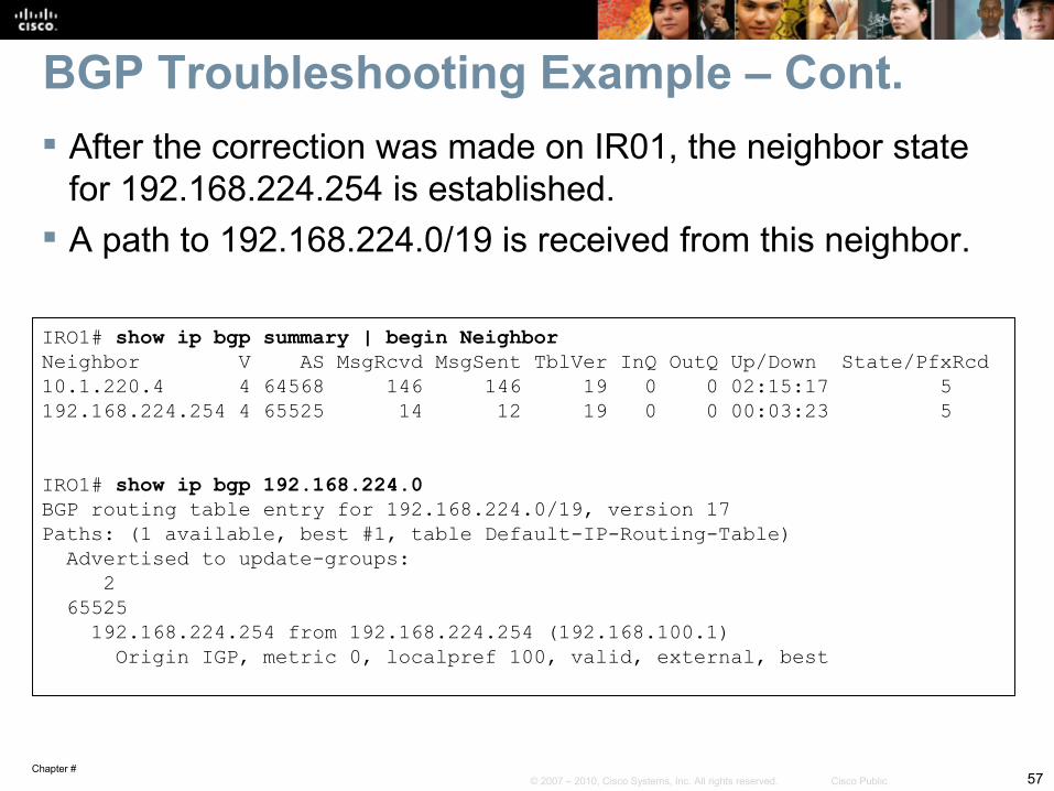
BGP Troubleshooting Example – Cont. After the correction was made on IR01, the neighbor state
for 192.168.224.254 is established. A path to 192.168.224.0/19 is received from this neighbor.
IRO1# show ip bgp summary | begin NeighborNeighbor V AS MsgRcvd MsgSent TblVer InQ OutQ Up/Down State/PfxRcd10.1.220.4 4 64568 146 146 19 0 0 02:15:17 5192.168.224.254 4 65525 14 12 19 0 0 00:03:23 5
IRO1# show ip bgp 192.168.224.0BGP routing table entry for 192.168.224.0/19, version 17Paths: (1 available, best #1, table Default-IP-Routing-Table) Advertised to update-groups: 2 65525 192.168.224.254 from 192.168.224.254 (192.168.100.1) Origin IGP, metric 0, localpref 100, valid, external, best
Chapter #58© 2007 – 2010, Cisco Systems, Inc. All rights reserved. Cisco Public
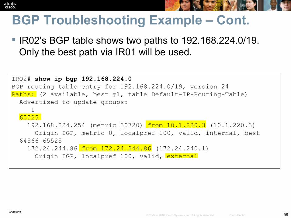
BGP Troubleshooting Example – Cont. IR02’s BGP table shows two paths to 192.168.224.0/19.
Only the best path via IR01 will be used.
IRO2# show ip bgp 192.168.224.0BGP routing table entry for 192.168.224.0/19, version 24Paths: (2 available, best #1, table Default-IP-Routing-Table) Advertised to update-groups: 1 65525 192.168.224.254 (metric 30720) from 10.1.220.3 (10.1.220.3) Origin IGP, metric 0, localpref 100, valid, internal, best 64566 65525 172.24.244.86 from 172.24.244.86 (172.24.240.1) Origin IGP, localpref 100, valid, external
Chapter #59© 2007 – 2010, Cisco Systems, Inc. All rights reserved. Cisco Public
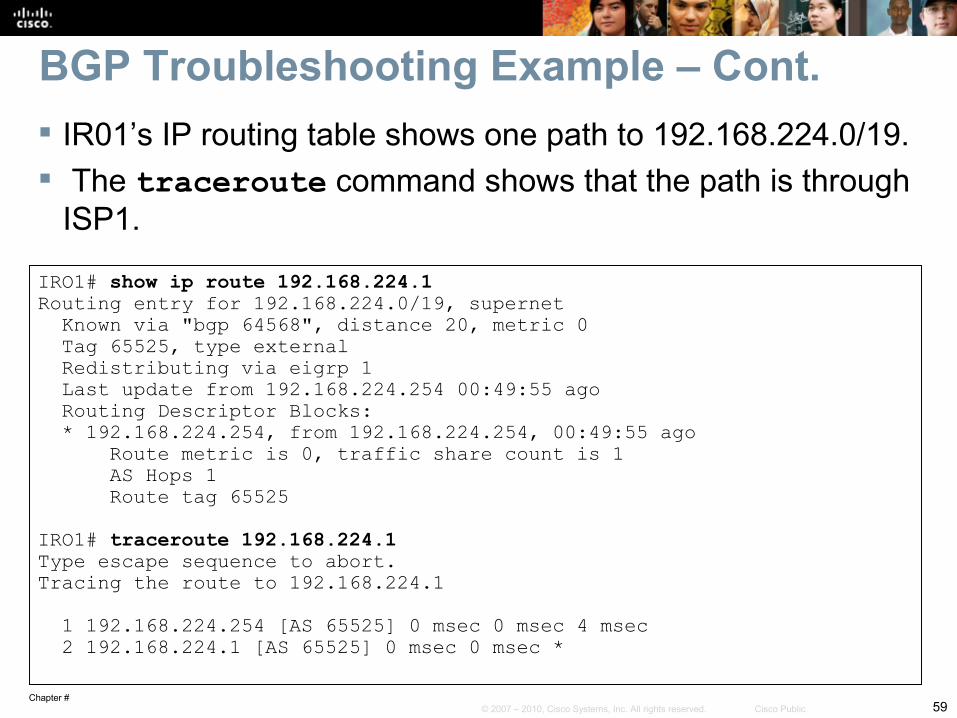
BGP Troubleshooting Example – Cont. IR01’s IP routing table shows one path to 192.168.224.0/19. The traceroute command shows that the path is through
ISP1.
IRO1# show ip route 192.168.224.1Routing entry for 192.168.224.0/19, supernet Known via "bgp 64568", distance 20, metric 0 Tag 65525, type external Redistributing via eigrp 1 Last update from 192.168.224.254 00:49:55 ago Routing Descriptor Blocks: * 192.168.224.254, from 192.168.224.254, 00:49:55 ago Route metric is 0, traffic share count is 1 AS Hops 1 Route tag 65525 IRO1# traceroute 192.168.224.1Type escape sequence to abort.Tracing the route to 192.168.224.1 1 192.168.224.254 [AS 65525] 0 msec 0 msec 4 msec 2 192.168.224.1 [AS 65525] 0 msec 0 msec *

Chapter #60© 2007 – 2010, Cisco Systems, Inc. All rights reserved. Cisco Public