Embed Size (px)
Citation preview
Deltona Water UTILITIES STANDARDS AND SPECIFICATIONS MANUAL CHAPTER 5 WASTEWATER Section 510: Gravity Wastewater System Standards and Specifications June 2018
Section 510
1 of 13
PART 1 – GENERAL
A. DELTONA WATER will not approve PLANS for combined wastewater gravity systems. Gravity mains shall be designed to exclude infiltration/inflow.
B. Wastewater gravity system shall be designed for the estimated ultimate tributary population, as delineated in the approved DELTONA WATER MASTER PLAN (latest edition). When the DEVELOPER’s MASTER PLAN is required, wastewater gravity mains shall be designed for the estimated ultimate build out of that DEVELOPMENT, as approved by DELTONA WATER.
PART 2 – LOCATION
A. Mains shall be located within dedicated public rights-of-way or CITY Utility Easements.
1. Public Rights-of-Way
When installed in rights-of-way, mains shall maintain a consistent alignment with respect to the centerline of the road. In all cases, mains shall be installed along one side of the road with crossings kept to a minimum.
2. City of Deltona Utility Easements
If a main is to be constructed within an easement, the centerline of the pipe shall be located along the centerline of the easement.
a. When not adjacent to state, county, or CITY rights-of-way, a minimum width of 20 feet shall be provided for mains with inverts located up to 5 feet below finish grade. For mains with inverts located deeper than 5 feet below finish grade, the minimum width shall be twice the invert depth of the main plus 10 feet. All widths shall be rounded up to the nearest even foot. Width of the easement shall be based on the deepest invert depth of each segment of the subject main.
b. Where multiple parallel mains are to be placed within a single easement, the FDEP required horizontal separation distance between the mains shall be added to the above minimum single main easement width and rounded up to the nearest even foot.
c. Have a maximum length of 150 linear feet if the easement terminates in a dead end or an obstruction. Longer easements may be authorized if adequate turnaround and work zone is provided as based on an AASHTO single unit vehicle. All locations and lengths of easements shall take in consideration the
Deltona Water UTILITIES STANDARDS AND SPECIFICATIONS MANUAL CHAPTER 5 WASTEWATER Section 510: Gravity Wastewater System Standards and Specifications June 2018
Section 510
2 of 13
d. safety and accessibility of DELTONA WATER vehicles and personnel.
e. Be free of any permanent structures, such as footers, foundations, walls, screen walls, buildings, air conditioner pads, transformer pads, sign supports, roof overhangs, stormwater structure, swimming pools, storage sheds, patios, etc.
f. Be accessible at all times and not subject to standing water nor under the side slope or bottom of a lake, pond or stormwater retention area, except that
perpendicular crossings under swales, small ditches and canals may be authorized in writing by DELTONA WATER.
g. As designated by DELTONA WATER for existing use, a CITY Utility Easement of not less than 15 feet in width shall be provided parallel to and directly adjacent to all federal, state, county, and CITY rights-of-way. Notwithstanding DELTONA WATER’s easement requirements stated above and herein, easements in typical subdivision construction including those adjacent to internal subdivision roads shall be sized and conveyed in accordance with the LAND DEVELOPMENT CODE. The ultimate width of easements may be based on the number, type, size and depth of the utility lines within the easement.
h. Landscape buffers may be allowed to co-exist with CITY Utility Easements as long as landscape berms are not utilized. Should DELTONA WATER disturb or damage any landscaping or other installed improvements within the easement, DELTONA WATER shall initiate repairs or install replacements in a timely manner at no cost to the property owner.
i. A triangular corner clip type of CITY Utility Easement, that has 20 foot long sides, shall be provided at all intersections of federal, state, county, and CITY rights-of-way.
B. Mains within easements shall not be placed under septic tanks, storm water management facilities, buildings, retention ponds, athletic courts, swimming pools, fountains, patios, or other structures. Privacy walls and foundations shall not be placed parallel over mains or within the structure’s zone of influence as based on a soil angle of repose of 45 degrees. Mains shall not be located along interior side or rear lot lines, unless approved in writing by DELTONA WATER. Placement of mains along storm water retention pond berms may be allowed by DELTONA WATER on a case-by-case basis when placed in a casing and if such a configuration results in efficient placement and utilization of the system. Service laterals, clean-outs, and other main related improvements shall not be placed along interior side or rear lot lines.
Deltona Water UTILITIES STANDARDS AND SPECIFICATIONS MANUAL CHAPTER 5 WASTEWATER Section 510: Gravity Wastewater System Standards and Specifications June 2018
Section 510
3 of 13
C. Mains may be accepted for maintenance if the private streets are designed with a urban
design cross section in accordance with the LAND DEVELOPMENT CODE. CITY Utility Easements shall be dedicated over the entire private street rights-of-way. In addition, sufficient area must be available outside of paved areas to maintain DELTONA WATER mains.
D. Offsite mains for all developments shall be extended along the entire frontage of each development. The minimum size of the main to be extended by the DEVELOPER shall be the same size that is the minimum main size required to serve the development. In the event that DELTONA WATER desires to upsize the main, DELTONA WATER shall reimburse the DEVELOPER for expenses relating to the upsizing.
E. Mains with inverts located up to 4 feet below finish grade shall not be located closer than 10 feet from any structure that requires a Certificate of Occupancy. For mains with inverts located deeper than 4 feet below finish grade, the minimum distance of 10 feet shall be increased by one foot for each one foot of increased depth of the main’s invert. All horizontal distances shall be rounded up to the nearest whole foot.
F. Unless specifically determined by DELTONA WATER to be of benefit to its overall system, gravity wastewater infrastructure installed within a non-residential or multi-residential development shall not be subject to ownership, maintenance, or operation by DELTONA WATER.
PART 3 – DESIGN BASIS
A. Average Daily Flow:
The gravity main design shall be based on ultimate development or projected flow. Average daily wastewater flow shall be calculated by the Equivalent Residential Connections (ERC) flow factors.
B. Peak Design Flow:
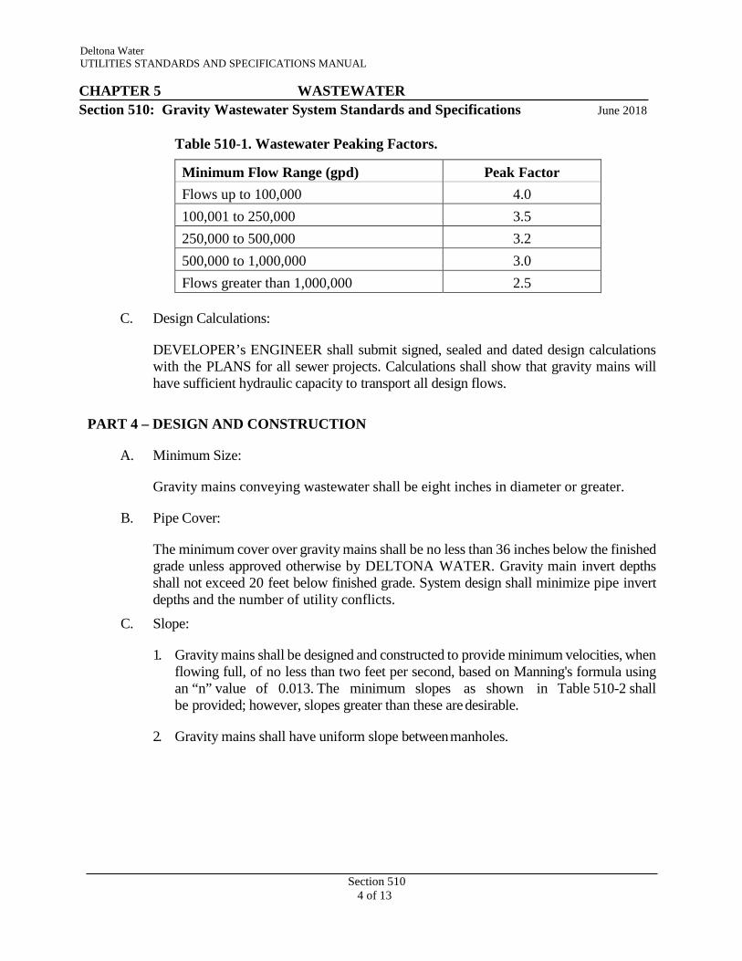
1. Gravity mains shall be designed on the basis of ultimate development maximum rates of flow, which shall be the product of selected peak factors multiplied by the accumulative average daily flow as calculated above. The minimum peaking factor, provided in Table 510-1 shall be applicable for the range of average daily flow rates.
Deltona Water UTILITIES STANDARDS AND SPECIFICATIONS MANUAL CHAPTER 5 WASTEWATER Section 510: Gravity Wastewater System Standards and Specifications June 2018
Section 510
4 of 13
Table 510-1. Wastewater Peaking Factors.
Minimum Flow Range (gpd) Peak Factor Flows up to 100,000 4.0 100,001 to 250,000 3.5 250,000 to 500,000 3.2 500,000 to 1,000,000 3.0 Flows greater than 1,000,000 2.5
C. Design Calculations:
DEVELOPER’s ENGINEER shall submit signed, sealed and dated design calculations with the PLANS for all sewer projects. Calculations shall show that gravity mains will have sufficient hydraulic capacity to transport all design flows.
PART 4 – DESIGN AND CONSTRUCTION
A. Minimum Size:
Gravity mains conveying wastewater shall be eight inches in diameter or greater.
B. Pipe Cover:
The minimum cover over gravity mains shall be no less than 36 inches below the finished grade unless approved otherwise by DELTONA WATER. Gravity main invert depths shall not exceed 20 feet below finished grade. System design shall minimize pipe invert depths and the number of utility conflicts.
C. Slope:
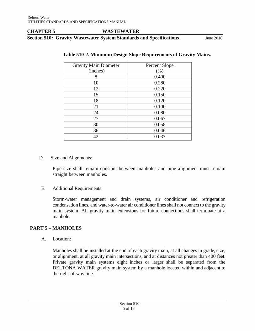
1. Gravity mains shall be designed and constructed to provide minimum velocities, when flowing full, of no less than two feet per second, based on Manning's formula using an “n” value of 0.013. The minimum slopes as shown in Table 510-2 shall be provided; however, slopes greater than these are desirable.
2. Gravity mains shall have uniform slope between manholes.
Deltona Water UTILITIES STANDARDS AND SPECIFICATIONS MANUAL CHAPTER 5 WASTEWATER Section 510: Gravity Wastewater System Standards and Specifications June 2018
Section 510
5 of 13
Table 510-2. Minimum Design Slope Requirements of Gravity Mains.
Gravity Main Diameter (inches)
Percent Slope (%)
8 0.400 10 0.280 12 0.220 15 0.150 18 0.120 21 0.100 24 0.080 27 0.067 30 0.058 36 0.046 42 0.037
D. Size and Alignments:
Pipe size shall remain constant between manholes and pipe alignment must remain straight between manholes.
E. Additional Requirements:
Storm-water management and drain systems, air conditioner and refrigeration condensation lines, and water-to-water air conditioner lines shall not connect to the gravity main system. All gravity main extensions for future connections shall terminate at a manhole.
PART 5 – MANHOLES
A. Location:
Manholes shall be installed at the end of each gravity main, at all changes in grade, size, or alignment, at all gravity main intersections, and at distances not greater than 400 feet. Private gravity main systems eight inches or larger shall be separated from the DELTONA WATER gravity main system by a manhole located within and adjacent to the right-of-way line.

Deltona Water UTILITIES STANDARDS AND SPECIFICATIONS MANUAL CHAPTER 5 WASTEWATER Section 510: Gravity Wastewater System Standards and Specifications June 2018
Section 510
6 of 13
B. Type:
1. Standard Manhole:
Where the difference in elevation between the incoming gravity main invert and the manhole invert is less than 24 inches, the manhole invert shall be filleted to prevent solids deposition. All standards manholes shall be coated in accordance with the appropriate “List of Approved Products”.
2. Drop Manhole:
An interior drop pipe shall be provided for wastewater gravity main entering a manhole where the invert elevation is 24 inches or more above the manhole invert. All drop manholes shall be lined or coated in accordance with the appropriate “List of Approved Products”.
3. Master Manhole:
All gravity and force mains shall discharge their flows into a master manhole prior to the wet well of a wastewater lift station. Force mains intersecting gravity main systems shall discharge into a master manhole at a maximum angle of 45 degrees to the flow path in the manhole. All master manholes shall be lined or coated and have a minimum interior diameter in accordance with Table 510-3.
C. Personnel Access Opening:
Manhole covers and frames shall provide a 24-inch minimum access clearance through the frame opening.
D. Diameter:
Manholes shall have minimum interior diameters from the structure’s base to the bottom of the top conical section as based on the main diameter in accordance with Table 510-3.
Table 510-3. Minimum Manhole Diameters.
Gravity Main Diameter (inches)
Minimum Inside Manhole Diameter (inches)
8 to 24 48 (60 for Master Manholes) 24 to 36 60
36 and larger 72
E. Flow Channel:
Deltona Water UTILITIES STANDARDS AND SPECIFICATIONS MANUAL CHAPTER 5 WASTEWATER Section 510: Gravity Wastewater System Standards and Specifications June 2018
Section 510
7 of 13
The flow channel through manholes shall be made to conform in shape and slope to that of the gravity mains. Flow direction changes in excess of 90 degrees shall not be included in gravity main alignments without written permission from DELTONA WATER. Flow line elevation drop of 0.1 feet across manholes shall be provided. Benching shall have a minimum downward slope of 1/2 inch per foot from the wall of the manhole towards the rim of the flow channel. No bricks shall be used to construct channels.
F. Materials:
1. Manholes shall be constructed of precast units as specified in this Section. Brick or cast-in-place manholes may be permitted on a case by case basis for retrofitting or repair purposes as approved by DELTONA WATER.
2. Wastewater pipes, valves, and appurtenances shall be constructed of materials as specified in Section 513 entitled “Wastewater Pipes, Valves, and Appurtenances Specifications”.
G. Castings:
All manhole frame and cover sets shall be in accordance with the STANDARD DRAWINGS and the appropriate “List of Approved Products.” Manholes that have 5 foot and larger inside diameters shall be provided with two piece covers in accordance with the STANDARD DRAWINGS. Bolt down covers shall be provided where manholes are located in areas outside of improved right-of-way and subject to ponding or flooding.
H. Vehicular Access:
A 12-foot wide access road shall be provided for all manholes that are located outside of state, county, and CITY roadways. The access road shall have a sub-base that is stabilized to a Florida Bearing value of 75 psi, and a base that is compacted to 98 percent of AASHTO T-180.
I. Coating or Lining:
A special coating or liner shall be provided for master manholes, drop manholes or any manhole that directly receives a discharge from a force main, as a minimum. A standard coating is required for other manholes. All coatings and liners shall be in accordance with the appropriate “List of Approved Products”.
J. Manhole Inserts:
All manhole cover and ring assemblies shall be furnished and installed complete with an

Deltona Water UTILITIES STANDARDS AND SPECIFICATIONS MANUAL CHAPTER 5 WASTEWATER Section 510: Gravity Wastewater System Standards and Specifications June 2018
Section 510
8 of 13
insert. The purpose of the insert is to prevent intrusion of storm water, dirt, debris, and to help control emission of odors.
The manhole insert shall be manufactured from corrosion-proof material, such as HDPE, polypropylene, or stainless steel, suitable for atmospheres containing hydrogen sulfide and diluted sulfuric acid and other gases associated with wastewater collection systems. The minimum continuous uniform thickness of a polymer based insert, including all angles, shall be 1/8 inch.
The body of the HPDE insert shall be made of high density polyethylene co-polymer material that meets ASTM D1248, Class A, Category 5, Type 111, and have a minimum impact brittleness temperature of – 180º F. As a minimum, the material
used in the manufacture of the body of the stainless steel insert shall be 16 gage Type 304 stainless steel.
The insert shall be manufactured to the dimensions of the manhole opening to allow easy installation within the manhole frame. The manhole insert shall be manufactured to fit the manhole frame rim upon which the manhole cover rests.
The gasket shall be made of closed cell neoprene. The gasket shall have a pressure sensitive adhesive on one side and be placed under the weight-bearing surface of the insert by the manufacturer. The adhesive shall be compatible with the insert material so as to form a long-lasting bond in either wet or dry conditions.
A lift strap shall be attached to the rising edge of the bowl insert. The lift strap shall be made of 1” wide woven polypropylene web and shall be seared on all cut ends to prevent unraveling. The lift strap shall be attached to the insert by means of a stainless steel rivet. Location of the strap shall provide easy visual location.
Ventilation of the insert shall be by means of a vent hole located on the side wall of the dish ¾” below the lip. The hole thus placed allows a maximum release of 10 gallons per 24 hours and is not affected by debris that might collect in the bottom of the bowl.
The insert shall have proof of durability in traffic impact loads and shall have engineer certified proof of test passing a collapse load of 2,200 pounds minimum applied to a 5.5” square area in the center of the insert.
The manhole frame shall be cleaned of all dirt and debris before placing the manhole insert on the rim. The manhole insert shall be fully seated around the manhole frame rim to retard water from seeping between the cover and the manhole frame rim.

Deltona Water UTILITIES STANDARDS AND SPECIFICATIONS MANUAL CHAPTER 5 WASTEWATER Section 510: Gravity Wastewater System Standards and Specifications June 2018
Section 510
9 of 13
K. Pre-Cast Concrete Sections:
1. Pre-cast manholes shall conform to specifications for ASTM C 478 “Pre-cast
Reinforced Concrete Manhole Sections”, except as otherwise specified below. 2. The minimum wall thickness shall be five inches. Pre-cast manholes shall be
constructed with a pre-cast monolithic base structure as shown on the STANDARD DRAWINGS. The minimum base thickness shall be eight inches.
3. Concrete for manholes shall be Type II, 4000 psi at 28 days. Barrel, top and base sections shall have tongue and groove joints. All jointing material shall be a cold adhesive preformed plastic gasket, conforming to ASTM C 443 “Manhole Section Connections”. Manholes shall be leak-free.
4. Sections shall be cured by an approved method as per ASTM C 478 for at least 28 the appropriate “List of Approved Products”.
L. Encapsulation:
1. Where a structure is subject to a high ground water condition, is within the
boundaries of a storm water management facility, or is subject to flooding, the cone, grade rings, joints, and iron frame shall be encapsulated with a heat shrink- wrap with a minimum final thickness of 100 mils unless otherwise approved by DELTONA WATER. The wrap shall have a cross-linked polyolefin backing coated with a protective heat activated adhesive. The wrap shall effectively bond to the substrate in order to provide corrosion and moisture protection. The PLANS shall specifically identify each structure that is designated to receive encapsulation.
M. Castings:
1. Gray iron castings for manhole frames, covers, adjustment rings and other items shall conform to the ASTM A 48, Class 30B. Castings shall be true to pattern in form and dimensions and free of pouring faults and other defects which would impair their strength or otherwise make them unfit for the service intended. The seating surfaces between frames and covers shall be machined to fit true. No plugging or filling will be allowed. Lifting or “pick” holes shall be provided, but shall not penetrate the cover. Casting patterns shall conform to those shown or indicated on the STANDARD DRAWINGS. All manhole frames and covers shall be traffic bearing to meet AASHTO H-20 loadings. Frames shall be suitable for the future addition of a cast iron ring for upward adjustment of top elevation.
N. Precast Concrete Manhole Installation:
1. Bedding, excavation, and backfill shall be in accordance with Section 312 entitled
“Excavations, Backfill, Compaction, and Grading Specifications”.
Deltona Water UTILITIES STANDARDS AND SPECIFICATIONS MANUAL CHAPTER 5 WASTEWATER Section 510: Gravity Wastewater System Standards and Specifications June 2018
Section 510
10 of 13
2. Placing Pre-Cast Sections:
a. The pre-cast base section shall be carefully placed on the prepared bedding so as to be fully and uniformly supported, in true alignment, and ensure that all pipes entering the structure shall be inserted to the proper grade.
b. Pre-cast manhole sections shall be handled by lift rings or non-penetrating lift holes. Such holes shall be filled with non-shrink grout after installation of the manhole and coated. Lifting of manhole sections shall be as per manufacturer’s recommendation.
c. Sections shall be uniformly supported by the base structure, and shall not bear directly on any of the pipes. Influent and effluent pipes shall be properly installed so as to form an integral watertight unit.
d. Sections shall be placed and aligned to provide vertical alignment with a 1/4- inch maximum tolerance per five feet of depth.
e. The completed manhole shall be rigid, true to dimensions, and watertight.
3. Placing Castings:
a. Casting shall be fully bedded in mortar with adjustment courses placed between the frame and manhole. Shall be HDPE, and shall accommodate a H-20 traffic load bearing design, per ‘List of Approved Products’.
b. Top of manhole castings located in pavement, shouldered areas, and sidewalks shall be set flush with grade. Top of manhole castings located outside these areas shall be placed in accordance with the STANDARD DRAWINGS.
4. Channels:
Manhole flow channels shall be constructed with smooth and carefully shaped bottoms, built up sides and benching using cement and brick with no voids. Channels shall conform to the dimension of the adjacent pipe and provide changes in size, grade and alignment evenly. Cement shall be Portland Cement Type II only.
5. Pipe Connections:
Special care shall be taken to ensure that the openings through which pipes enter the structure are provided with watertight connections. Pipe connections shall conform to ASTM C 923, "Standard Specifications for Resilient Connectors Between Reinforced Concrete Manhole Structures, Pipes, and Laterals".
O. Cleaning:
Deltona Water UTILITIES STANDARDS AND SPECIFICATIONS MANUAL CHAPTER 5 WASTEWATER Section 510: Gravity Wastewater System Standards and Specifications June 2018
Section 510
11 of 13
1. Newly constructed manholes shall be cleaned of any accumulation of silt, debris, or foreign matter of any kind and shall be free from such accumulations at the time of final inspection.
P. Inspection for Acceptance:
1. The quality of materials, the process of manufacture and the finished sections shall be
subject to inspection and approval by DELTONA WATER. Such inspection may be made at the place of manufacture, at the site after delivery or at both places and the sections shall be subject to rejection at any time due to failure to meet any of the specification requirements; even though sample sections may have been accepted as satisfactory at the place of manufacture. Sections rejected after delivery to the job shall be marked for identification and shall be removed from the job at once. Sections that have been damaged after delivery will be rejected and if already installed, removed and replaced, entirely at the CONTRACTOR’s expense.
2. At the time of inspection, the sections will be carefully examined for compliance
with the specified ASTM designation and with the approved manufacturer’s drawings. Sections shall be inspected for general appearance, dimension, “scratch- strength” blisters, cracks, roughness, soundness, etc. The surface shall be dense and close-textured.
3. Manholes shall be inspected by DELTONA WATER and defective manholes replaced by the CONTRACTOR. Pressure grouting of manholes for repair shall not be accepted.
PART 6 – SERVICE LATERAL CONNECTIONS
A. Service connections shall be as shown in the STANDARD DRAWINGS. B. Service connections shall be permanently marked by cutting an “S” in the curb in direct
alignment with the wye and the installation of a stake at the temporary plug to indicate the location of the service pipe as per the STANDARD DRAWINGS.
C. Size and Length: Service laterals and fittings shall be a minimum of six inches in diameter for single services. No double services are permitted. Service laterals shall be laid perpendicular to the receiving main, in cul-de-sacs, service laterals shall not be connected to an upstream terminal manhole. Service laterals shall not exceed 150 feet. Service laterals shall terminate with a temporary plug at the right-of-way with individual cleanouts installed by the building’s plumber in accordance with the STANDARD DRAWINGS.
Deltona Water UTILITIES STANDARDS AND SPECIFICATIONS MANUAL CHAPTER 5 WASTEWATER Section 510: Gravity Wastewater System Standards and Specifications June 2018
Section 510
12 of 13
D. Slope:
Service laterals shall have a minimum slope of one percent. E. If a floor slab elevation is lower than the closest manhole top elevation, then a private
prefabricated pump station with a check valve (for each occurrence) shall be required to pump wastewater to the lateral at the cleanout in the road right-of-way. The private pump station shall be operated and maintained by the property OWNER.
F. Connection:
Service laterals shall not be directly connected to sanitary manholes. Incoming flows shall not be more than 90 degrees to the flow path in the manhole.
PART 7 – GREASE TRAPS, INTERCEPTORS, AND SEPARATORS
A. Grease interceptors shall be required for all commercial establishments where food will be processed or cooked in any way. The grease interceptor will be sized as defined below and will have a minimum volume of 750 gallons. All kitchen waste lines will be routed through the grease interceptor. However, no domestic waste will be allowed to enter the grease interceptor. All wastewater flow from the kitchen areas of these establishments shall flow through approved grease interceptors prior to entering the DELTONA WATER system. In some cases, a grinder may be required for meat and fish processing plants.
B. Grease interceptors shall be located outside of buildings. C. Sizing:
Refer to Table 510-4 for sizing requirements. D. Grease interceptors shall be placed where the proposed food waste line will have
adequate slope and be accessible for maintenance and inspection at all times. E. Under-the-Counter Grease Traps:
1. Where location of an outside grease interceptor is determined not feasible by DELTONA WATER, DELTONA WATER may approve an under-the-counter grease trap on a case-by-case basis. A commercial establishment where food will be processed or handled will only be considered for an under-the-counter grease trap if it meets all of the following criteria:
a. The building must be in existence at the time the under-the-counter grease trap is being proposed;
b. The restaurant or food preparation establishment must have less than 600 gpd of wastewater flow;
c. An under-the-counter grease trap must be installed on all drain fixtures in the food preparation areas; and
Deltona Water UTILITIES STANDARDS AND SPECIFICATIONS MANUAL CHAPTER 5 WASTEWATER Section 510: Gravity Wastewater System Standards and Specifications June 2018
Section 510
13 of 13
d. ENGINEER shall consult with DELTONA WATER personnel before finalizing
the design.
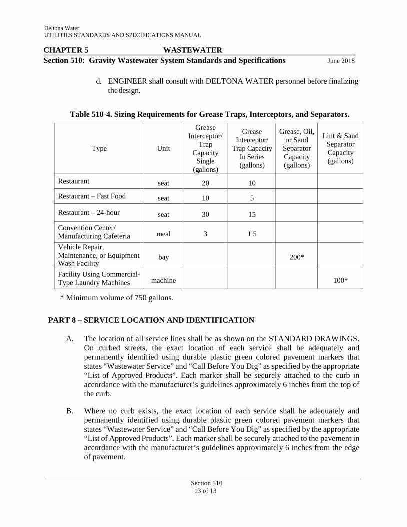
Table 510-4. Sizing Requirements for Grease Traps, Interceptors, and Separators.
Type
Unit
Grease Interceptor/
Trap Capacity
Single (gallons)
Grease Interceptor/
Trap Capacity In Series (gallons)
Grease, Oil, or Sand
Separator Capacity (gallons)
Lint & Sand
Separator Capacity (gallons)
Restaurant seat 20 10
Restaurant – Fast Food seat 10 5
Restaurant – 24-hour seat 30 15
Convention Center/ Manufacturing Cafeteria
meal
3
1.5
Vehicle Repair, Maintenance, or Equipment Wash Facility
bay
200*
Facility Using Commercial- Type Laundry Machines
machine
100*
* Minimum volume of 750 gallons.
PART 8 – SERVICE LOCATION AND IDENTIFICATION
A. The location of all service lines shall be as shown on the STANDARD DRAWINGS. On curbed streets, the exact location of each service shall be adequately and permanently identified using durable plastic green colored pavement markers that states “Wastewater Service” and “Call Before You Dig” as specified by the appropriate “List of Approved Products”. Each marker shall be securely attached to the curb in accordance with the manufacturer’s guidelines approximately 6 inches from the top of the curb.
B. Where no curb exists, the exact location of each service shall be adequately and permanently identified using durable plastic green colored pavement markers that states “Wastewater Service” and “Call Before You Dig” as specified by the appropriate “List of Approved Products”. Each marker shall be securely attached to the pavement in accordance with the manufacturer’s guidelines approximately 6 inches from the edge of pavement.

Deltona Water UTILITIES STANDARDS AND SPECIFICATIONS MANUAL
Section 511 1 of 4
CHAPTER 5 WASTEWATER
Section 511: Wastewater Force Main Standards June 2018
PART 1 – GENERAL A. Force main systems shall be designed for the estimated tributary population, as
delineated in the approved DELTONA WATER’s MASTER PLAN (latest edition) for the subject RUSA. When DEVELOPER’s wastewater MASTER PLANS are required, force mains shall be designed for the estimated ultimate build out, as approved by DELTONA WATER.
PART 2 – LOCATION
A. Refer to Section 510 entitled “Gravity Wastewater System Standards and Specifications”.
PART 3 – DESIGN BASIS
A. Average Daily Flow and Peak Flows: Average daily wastewater flow shall be calculated by referencing the equivalent residential unit flow factors. Peak hourly wastewater flow rates shall be calculated by referencing the minimum peaking factors as specified in Section 510 entitled “Gravity Wastewater System Standards and Specifications”.
B. Design Calculations: The ENGINEER shall submit signed, sealed, and dated design calculations along with a compact disc copy of the SewerCad based model with the PLANS for all DELTONA WATER projects. Calculations shall show that the mains will have sufficient hydraulic capacity for peak hourly flows while meeting the requirements of this Section. Minor head losses shall be incorporated in the calculations.
PART 4 – DESIGN
A. Pipe Cover: A minimum cover of 36 inches shall be provided.
B. Velocity and Diameter: At design pumping rates, a cleansing velocity of at least 2.0 feet per second shall be maintained. DELTONA WATER reserves the right to require velocities > 2.0 ft/sec in applications deemed appropriate. Maximum velocity at design pumping rates should not exceed six feet per second. The minimum force main diameter shall be four inches when connected to a single lift station and is internal of a single development. The ENGINEER shall also provide calculations showing that upsizing the proposed offsite force main has been considered in an effort to downsize the proposed lift station pumps. Only 4, 6, 8, 10, 12, 16, 18, 20, 24, 30, 36, 42, 48, and 54-inch diameter force mains shall be permitted. Variations in main size may be authorized by DELTONA WATER when deemed appropriate provided that the existing or proposed level of service is maintained and operational maintenance and responsibility is established to the benefit of the CITY. Using the DELTONA WATER approved hydraulic standards contained within this MANUAL, the ENGINEER shall determine on a case-by-

Section 511 2 of 4
Deltona Water UTILITIES STANDARDS AND SPECIFICATIONS MANUAL
CHAPTER 5 WASTEWATER
Section 511: Wastewater Force Main Standards June 2018
Case basis if it is necessary for all proposed HDPE pipe installations to be increased by one pipe size above all proposed or existing adjacent PVC and Ductile Iron Pipe installations.
C. Design Friction Losses: Friction losses through mains shall be based on the Hazen-Williams or Darcy-Wiesbach formula. In the use of the Hazen-Williams formula, the value for “C” shall be 130.
D. Design Pressure and Restraint: 1. The main and fittings, including all restrained joint pipe fittings, shall be designed to
withstand pump operating pressures and pressure surges, but not less than 150 psi. The restrained joint lengths shall be calculated consistent with the table format shown in the STANDARD DRAWINGS.
2. In the event that it is necessary to locate proposed mains or leave existing mains longitudinally under any part of a proposed roadway subject to regular non- residential traffic or with speed limits above 30 miles per hour, such mains shall have restrained joints.
E. Pigging Ports:
Provision for the installation of permanent access points into and egress points out of the piping system for pigging and cleaning purposes shall be incorporated into 8 inch and larger force mains. Wherever possible, pigging ports shall be located and incorporated within the lift station sites. Permanent and temporary access and egress points shall conform to the STANDARD DRAWINGS.
F. Mains shall be designed with uniform positive or negative slopes to avoid undulations and minimize high points and low points in the profile.
G. Offsite mains for all developments shall be extended along the entire frontage of each development. The minimum size of the main to be extended by the DEVELOPER shall be the same size that is the minimum main size required to serve the development. In the event that DELTONA WATER desires to upsize the main, DELTONA WATER shall reimburse the DEVELOPER for expenses related to the upsizing.
F. Mains with inverts located up to 5 feet below finish grade shall not be located closer than 10 feet from any structure that requires a Certificate of Occupancy. For mains with inverts located deeper than 5 feet below finish grade, the minimum distance of 10 feet shall be increased by one foot for each one foot of increased depth of the main’s invert. All horizontal distances shall be rounded up to the nearest whole foot.
G. Unless specifically determined by DELTONA WATER to be of benefit to its overall system, wastewater force main infrastructure installed within a non-residential or multi- residential development shall not be subject to ownership, maintenance, or operation by DELTONA WATER.
H. Materials:
1. Force mains shall be constructed of PVC pipe, with epoxy coated Ductile Iron fittings.
Section 511 3 of 4
Deltona Water UTILITIES STANDARDS AND SPECIFICATIONS MANUAL
CHAPTER 5 WASTEWATER
Section 511: Wastewater Force Main Standards June 2018
2. HDPE may be used in specific applications as specified in this MANUAL or as approved by DELTONA WATER. Using the DELTONA WATER approved hydraulic standards contained within this MANUAL, the ENGINEER shall determine on a case by case basis if it is necessary for all proposed HDPE pipe installations to be increased by one pipe size above all proposed or existing adjacent PVC and Ductile Iron Pipe installations.
PART 5 – TERMINATION POINT
A. Force mains shall enter a gravity sewer system a maximum of one foot above the flow line of the receiving master manhole and be orientated no greater than 45 degrees to the flow path in the manhole. The interior surfaces of the receiving master manhole shall have a protective coating or lining. Force mains shall terminate directly into a wastewater master manhole or connect to another force main. Termination into gravity mains is not allowed.
PART 6 – AUTOMATIC AIR RELEASE VALVES
A. Automatic air release valves of appropriate size and number shall be provided to prevent air locking formation. Automatic combination air and vacuum release valves shall be utilized to prevent both air locking and vacuum formation. All such valves are required at the high points of the main or as specified by DELTONA WATER. Valves shall be clearly delineated on the main profile in the STANDARD DRAWINGS. The ENGINEER shall submit calculations to DELTONA WATER justifying the valve sizes and numbers as specified by AWWA M- 51 “Air Release, Air/Vacuum, and Combination Air Valves”.
PART 7 – VALVES
A. Valves shall be located on force main systems to facilitate effective isolation of the pipe system for repairs and maintenance. In accordance with the recommendations issued by valve manufacturers, gate valves shall not be installed on their side when used within a force main system. On straight runs of force mains, valve spacing shall not exceed 2,000 feet. Additional valves shall be provided where force mains intersect to facilitate isolation of pipe segments. Valves shall be installed on private forces and located adjacent to and within public rights-of-way lines or CITY Utility Easement boundary lines in order to isolate private force mains and lift stations from the DELTONA WATER system in case of the malfunction of such improvements.
PART 8 – FORCE MAIN VALVE LOCATION AND IDENTIFICATION
A. On curbed streets, the exact location of each force main valve shall be adequately and permanently identified using durable plastic green colored pavement markers that states “Force Main Valve” and “Call 811 Before You Dig” as specified by the appropriate “List of Approved Products”. Each marker shall be securely attached to the curb in accordance with the manufacturer’s guidelines approximately 6 inches from the top of the curb.
Section 511 4 of 4
Deltona Water UTILITIES STANDARDS AND SPECIFICATIONS MANUAL
CHAPTER 5 WASTEWATER
Section 511: Wastewater Force Main Standards June 2018
B. Where no curb exists, the exact location of each force main valve shall be adequately and permanently identified using durable plastic green colored pavement markers that states “Force Main Valve” and “Call 811 Before You Dig” as specified by the appropriate “List of Approved Products”. Each marker shall be securely attached to the pavement in accordance with the manufacturer’s guidelines approximately 6 inches from the edge of pavement.

Deltona Water UTILITIES STANDARDS AND SPECIFICATIONS MANUAL CHAPTER 5 WASTEWATER
Section 512: Wastewater Lift Station Standards and Specifications June 2018
Section 512
1 of 19
PART 1 – GENERAL
1.01 The design standards outlined in this Section apply to all wastewater lift stations within the jurisdiction of this MANUAL. All stations shall be submersible type stations. The basis of design shall be reviewed and approved by DELTONA WATER.
1.02 Lift stations shall be designed for the estimated ultimate tributary population, as delineated in one of the approved DELTONA WATER MASTER PLANS (latest edition) for the subject Regional Utility Service Area. When a DEVELOPER’s master plan is required, lift stations shall be designed for the estimated ultimate build out of that DEVELOPMENT, as approved by DELTONA WATER.
1.03 Unless specifically determined by DELTONA WATER to be of benefit to its overall system, wastewater lift stations installed within a non-residential or multi-residential development shall not be subject to ownership, maintenance, or operation by DELTONA WATER.
1.04 Regional lift stations shall have wet wells designed and constructed to serve the lowest developable point on all adjacent vacant tracts of land surrounding a project by means of gravity flow only. The appropriate sized CITY Utility Easement(s) shall be provided by the DEVELOPER so that the gravity wastewater mains from all such vacant tracts of land can easily be connected to the wet well of the regional lift station.
1.05 All lift stations to be dedicated to and operated by DELTONA WATER shall be of the municipal rated type.
PART 2 – LOCATION
2.01 With the exception of private lift stations serving single owner properties, all lift stations shall be located on fee simple tracts of land adjacent to rights-of-way and preferably sharing the same general location as stormwater management facilities. Private lift stations shall not be located directly adjacent to public thoroughfares. No part of a lift station, regardless of ownership, shall be located in a roadway median, in the middle of a cul-de-sac, within any portion of a public or private right-of-way, directly in front or behind of an occupied structure on the same side of the roadway, or less than 50 feet perpendicularly from the intersection of two or more rights-of-way. The actual location of all equipment within a lift station site shall be in accordance with the STANDARD DRAWINGS or as approved by DELTONA WATER.
2.02 No public or private easement or non-DELTONA WATER infrastructure of any kind shall be permitted to cross a tract containing a DELTONA WATER lift station without written approval by DELTONA WATER. Where conflicts are unavoidable in the opinion of DELTONA WATER, the depth of the lift station tract shall be extended so that the required minimum dimensioned lift station site is located directly behind and adjacent to the conflicting easement or infrastructure.
Deltona Water UTILITIES STANDARDS AND SPECIFICATIONS MANUAL CHAPTER 5 WASTEWATER
Section 512: Wastewater Lift Station Standards and Specifications June 2018
Section 512
2 of 19
2.03 Permanent and temporary vehicular access to a lift station shall freely accommodate the turning movements of a 40-foot-long and 9-foot-wide single unit truck vehicle with a 28-foot wheelbase as specified by the Institute of Transportation Engineers. Vehicular backup distance shall not exceed 60 linear feet. A T-shaped turn-around with the appropriate radii and pavement lengths may be considered as part of the access design. The design of the access driveway or roadway shall insure that the ramp break-over angle of a two-wheel drive pickup truck with a standard wheelbase is accommodated along its entire length.
2.04 Driveways to lift stations along low traffic volume two lane residential roadways shall not be less than 23-feet in length from the lift station’s gates to the adjacent roadway’s edge of pavement or back of curb so as not to totally block both lanes of travel. The driveway length along all other roadways shall not be less than 45-feet so as to accommodate the entire length of the vehicle described above without impeding traffic in any travel lane. Driveway within DELTONA WATER lift station tract shall be a minimum of 40-feet in length to accommodate the entire length of the vehicle described above within the tract.
PART 3 – DESIGN BASIS
3.01 AVERAGE DAILY FLOW
The wastewater lift station design shall be based on ultimate development or projected flow. Average daily wastewater flow shall be calculated by Equivalent Residential Unit flow factors.
3.02 PEAK DESIGN FLOW
The design pumping capability of the station shall be based upon the peak design flow, which shall be calculated by multiplying the design average flow with the applicable minimum peaking factors as outlined in Table 510-1, “Wastewater Peaking Factors”.
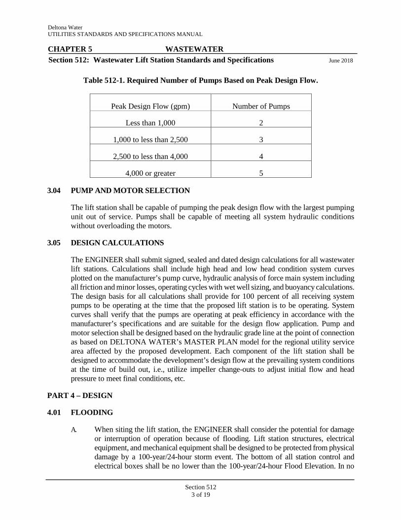
3.03 NUMBER OF PUMPS
Minimum number of pumps is determined by the peak design flow as shown in Table 512-1 below.
Deltona Water UTILITIES STANDARDS AND SPECIFICATIONS MANUAL CHAPTER 5 WASTEWATER
Section 512: Wastewater Lift Station Standards and Specifications June 2018
Section 512
3 of 19
Table 512-1. Required Number of Pumps Based on Peak Design Flow.
Peak Design Flow (gpm) Number of Pumps
Less than 1,000 2
1,000 to less than 2,500 3
2,500 to less than 4,000 4
4,000 or greater 5
3.04 PUMP AND MOTOR SELECTION
The lift station shall be capable of pumping the peak design flow with the largest pumping unit out of service. Pumps shall be capable of meeting all system hydraulic conditions without overloading the motors.
3.05 DESIGN CALCULATIONS
The ENGINEER shall submit signed, sealed and dated design calculations for all wastewater lift stations. Calculations shall include high head and low head condition system curves plotted on the manufacturer’s pump curve, hydraulic analysis of force main system including all friction and minor losses, operating cycles with wet well sizing, and buoyancy calculations. The design basis for all calculations shall provide for 100 percent of all receiving system pumps to be operating at the time that the proposed lift station is to be operating. System curves shall verify that the pumps are operating at peak efficiency in accordance with the manufacturer’s specifications and are suitable for the design flow application. Pump and motor selection shall be designed based on the hydraulic grade line at the point of connection as based on DELTONA WATER’s MASTER PLAN model for the regional utility service area affected by the proposed development. Each component of the lift station shall be designed to accommodate the development’s design flow at the prevailing system conditions at the time of build out, i.e., utilize impeller change-outs to adjust initial flow and head pressure to meet final conditions, etc.
PART 4 – DESIGN
4.01 FLOODING
A. When siting the lift station, the ENGINEER shall consider the potential for damage or interruption of operation because of flooding. Lift station structures, electrical equipment, and mechanical equipment shall be designed to be protected from physical damage by a 100-year/24-hour storm event. The bottom of all station control and electrical boxes shall be no lower than the 100-year/24-hour Flood Elevation. In no
Deltona Water UTILITIES STANDARDS AND SPECIFICATIONS MANUAL CHAPTER 5 WASTEWATER
Section 512: Wastewater Lift Station Standards and Specifications June 2018
Section 512
4 of 19
case shall the top elevation of the control panel exceed the maximum distance from the lift station’s concrete pad that is allowed by the NEC. In such cases, the elevation of the lift station’s entire concrete pad shall be raised until the maximum distance allowed by the NEC is achieved.
B. Wastewater lift stations shall remain fully operational and accessible during a 25-year/24-hour storm event. The top elevation of the wet well shall be no lower than the 25-year/24-hour Flood Elevation. On a case-by-case basis, the top elevation of the wet well may be lower if it can be shown that no drainage runoff from the surrounding areas will flow to the lift station site at any time.
C. No occupied structures shall have a floor, which is connected by gravity flow to a DELTONA WATER wastewater system, with a finish floor elevation below the top elevation of the lift station that serves it. Regulations of federal, state, and local agencies regarding flood plains shall be considered.
D. The lift station site design shall insure positive storm water drainage radiates outward from the center of the wet well to the boundaries of the site and away from the lift station site. The access driveway or roadway shall not allow storm water to be conveyed onto the lift station site.
4.02 ACCESSIBILITY
A. The lift station shall be readily accessible by maintenance vehicles during all weather conditions including a 25-year/24-hour storm event. The lift station driveway shall be concrete onsite while the offsite portion may be either concrete or asphaltic concrete in accordance with the STANDARD DRAWINGS. In a phased development, a temporary 12-foot-wide paved asphalt access road (1½ inch thick FDOT SP-9.5 Asphaltic Concrete, 6-inch-thick LBR 40 Limerock Base, and 6-inch-thick FBV 75 Sub-Base) within the appropriately sized CITY Utility Easement, shall be provided by the DEVELOPER and utilized by DELTONA WATER until the temporary access is replaced with a platted roadway that complies with this MANUAL.
4.03 BOUNDARY SURVEY
A. A current BOUNDARY SURVEY shall be required at the lift station startup test and inspection. The DEVELOPER shall bear the entire expense of rectifying WORK improperly installed due to the construction of improvements not totally within the fee simple site to be dedicated to DELTONA WATER. An electronic version and three copies of the certified BOUNDARY SURVEY shall be required.
Deltona Water UTILITIES STANDARDS AND SPECIFICATIONS MANUAL CHAPTER 5 WASTEWATER
Section 512: Wastewater Lift Station Standards and Specifications June 2018
Section 512
5 of 19
4.04 PUMP REQUIREMENTS
A. Pump rails and base elbows shall be capable of accepting an ABS, FLYGT, Grundfos, or approved equal brand pump by sliding a pump down the rails and accomplish a positive seal to the base elbow with no adapters. When other pump brands are considered as specified in the appropriate “List of Approved Products”, they shall be required to be adaptable to the above applicable standards. Submersible pumps shall be readily removable and replaceable without dewatering the wet well or disconnecting any piping in the wet well.
B. Pumps shall be capable of handling raw sewage and passing solids of at least three inches in diameter. Pump suction and discharge openings shall be at least four inches in diameter. No pumps with less than five horsepower motors will be acceptable.
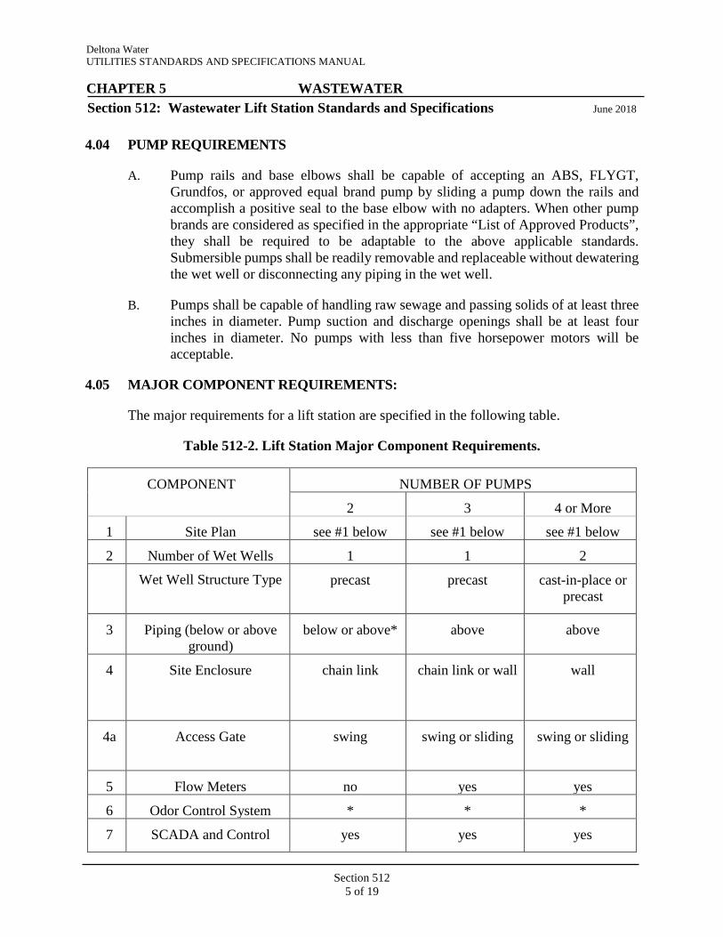
4.05 MAJOR COMPONENT REQUIREMENTS:
The major requirements for a lift station are specified in the following table.
Table 512-2. Lift Station Major Component Requirements.
COMPONENT NUMBER OF PUMPS
2 3 4 or More
1 Site Plan see #1 below see #1 below see #1 below
2 Number of Wet Wells 1 1 2
Wet Well Structure Type precast precast cast-in-place or precast
3 Piping (below or above ground)
below or above* above above
4 Site Enclosure chain link chain link or wall wall
4a Access Gate swing swing or sliding swing or sliding
5 Flow Meters no yes yes
6 Odor Control System * * *
7 SCADA and Control yes yes yes

Deltona Water UTILITIES STANDARDS AND SPECIFICATIONS MANUAL CHAPTER 5 WASTEWATER
Section 512: Wastewater Lift Station Standards and Specifications June 2018
Section 512
6 of 19
Panel
8 Generator * yes yes
9 A/C MCC no no yes
10 VFD no * *
11 Wet Well / Coating/ Liner yes yes yes
12 Level Control float ball float ball float ball
13 Automatic Gear Actuator * * *
14 Wet Well Fall Protection System
yes yes yes
NOTE: Please refer below for component explanation.
* In accordance with MANUAL or as determined by DELTONA WATER for proper system operation.
4.06 SITE SIZING, TRACT, AND EASEMENT REQUIREMENTS
Lift station sites shall be sized as delineated in the STANDARD DRAWINGS for the duplex, triplex, or more than three pumps per the lift station site plans. The DEVELOPER shall dedicate the lift station site and driveway by plat or separate instrument to DELTONA WATER. Dedicated easements shall be shown as specified on the lift station site plans in the STANDARD DRAWINGS. All temporary access roads shall be improved to accommodate heavy truck traffic and dedicated to DELTONA WATER, with a minimum 20-foot-wide CITY Utility Easement that provides for ingress and egress to the lift station.
4.07 WET WELL REQUIREMENTS
A. Single wet well:
1. The wet well for a duplex lift station shall have a minimum six feet inside diameter. If the design requirements require 35 horsepower pumps or larger for a duplex lift station (less than 1,000 gpm), a minimum 10-foot inside diameter wet well shall be required. Sufficient depth shall be provided to accommodate cycle time and motor submergence.
2. The wet well for a triplex lift station shall have a minimum 12-foot inside diameter. Sufficient depth shall be provided to accommodate cycle time and motor submergence.
3. In determining the cycle time, no consideration of volume shall be used for
Deltona Water UTILITIES STANDARDS AND SPECIFICATIONS MANUAL CHAPTER 5 WASTEWATER
Section 512: Wastewater Lift Station Standards and Specifications June 2018
Section 512
7 of 19
the volume below the top of the pump or the manufacturer’s minimum submergence recommendation, whichever is greater.
4. Pumping levels shall be set to provide a minimum capacity between operational water levels sufficient to allow a minimum of ten minutes in one pumping cycle. The minimum time between successive starts of the same pump shall be ten minutes.
5. For duplex lift stations (less than 1,000 gpm), the effective volume (from pump off elevation to the invert of the gravity pipe) shall be based on a fill time of 30 minutes at Average Daily Flow (ADF). For triplex lift stations, the fill time shall not exceed 10 minutes at ADF. The high liquid level in the wet well (storage capacity) shall not exceed the invert elevation of the lowest inflow pipe. When new development proposes connection to an existing lift station, vertical storage criteria within the wet well shall not be applied to the existing lift station without consideration of other factors including, but not limited to generator installation.
6. Pump-off water levels shall provide adequate submergence to preclude pump inlet cavitations. Design maximum water levels shall not exceed the invert elevation of the influent pipe.
7. The wet well floor shall have a minimum slope of one to one to the hopper bottom. The horizontal area of the hopper bottom shall be no greater than necessary for proper installation and function of the pump inlet.
8. Interior ladders shall not be permitted.
9. Only one inlet connection shall be permitted to a wet well.
10. For buoyancy calculations, the soil ring weight (from the outer face of the bottom slab to the outer edge of the wet well) shall be 100 percent of the total weight of the soil ring. The net density of the soil shall be used for calculating weight, i.e., soil density less the water density (62.4 pounds per cubic foot). A minimum safety factor of 1.1 shall be achieved.
B. Dual wet wells:
1. When required, dual wet wells shall be designed with the same criteria as a single wet well; except with master manhole and valving to separate either wet well. The influent slope of the wet well floor shall have a minimum slope one inch per foot to the hopper bottom.

Deltona Water UTILITIES STANDARDS AND SPECIFICATIONS MANUAL CHAPTER 5 WASTEWATER
Section 512: Wastewater Lift Station Standards and Specifications June 2018
Section 512
8 of 19
4.08 PIPING ABOVE GROUND
Piping shall be installed above ground with a concrete slab.
4.09 SITE ENCLOSURES
A. All lift station sites shall be enclosed. Duplex lift stations shall have six-foot high factory applied black vinyl security type chain link fencing with two offset six-foot-high chain link double swing gates or one single six-foot-high chain link rolling type gate as specified by DELTONA WATER. DELTONA WATER may require that lift stations with more than two pumps have eight-foot high concrete masonry unit perimeter walls and two offset eight-foot high minimum aluminum, double-hung swing gates instead of the required chain link fencing and gates. The use or substitution of chain link fencing slats, vinyl fencing, or wood fencing instead of or in addition to the black vinyl coated chain link fencing shall be prohibited. Three strands of barb wire shall be installed on top of the chain link fencing at the direction of DELTONA WATER if it is determined to be necessary for site security.
B. Florida-Friendly Landscaping may be permitted along the outside perimeter fencing of the lift station site as long as the center of all trees are no closer than 15-feet and the center of all other non-tree type plantings are no closer than 5-feet. Maintenance and irrigation of the landscaping shall be the responsibility of the installing entity and not DELTONA WATER.
4.10 FLOW METERS:
A. Indicating, totalizing, and recording flow measurement devices shall be provided at lift stations where required in Table 512-2. Bypass piping around the meter shall be provided for all stations with flow meters to facilitate meter maintenance.
4.11 ODOR CONTROL SYSTEM
A. Provide a complete system for the control of hydrogen sulfide gas and other wastewater odors as required and specified by DELTONA WATER.
4.12 SCADA
A. Control Panel:
1. Panel shall be of type to match lift station configuration (number of pumps, control features, etc.) as determined by DELTONA WATER. Refer to Chapter 7 entitled “SCADA and Control Panel Specifications” for additional information.
Deltona Water UTILITIES STANDARDS AND SPECIFICATIONS MANUAL CHAPTER 5 WASTEWATER
Section 512: Wastewater Lift Station Standards and Specifications June 2018
Section 512
9 of 19
4.13 EMERGENCY GENERATOR
A. Permanent stationary emergency generator sets shall be provided for all lift stations that utilize a 12-inch and larger force main, receive flows from one or more contributing lift stations, that receive flow from a generator equipped tributary lift station, pump more than 1,000 gpm, or as required by FDEP.
B. The ENGINEER shall size the generator and fuel tank as required by DELTONA WATER and submit the name of the manufacturer, burn rate specifications, and sizing calculations to DELTONA WATER for review and approval. The generator and fuel tank manufacturer shall be as specified in the appropriate “List of Approved Products”.
C. Lift stations shall be provided with manual transfer switches or emergency power receptacles, except for those lift stations with permanent stationary emergency generator sets, as specified in Section 516 entitled “Wastewater Lift Station Electrical System Specifications”.
4.14 AIR-CONDITIONED MOTOR CONTROL CENTER
A. When a motor control center is required, a fully enclosed structure of concrete masonry unit construction with a stucco exterior on a concrete slab, prestressed concrete roof slab with built-up roofing, R-4 insulated or greater interior walls, and R-19 insulated suspended ceiling shall be provided. As specifically approved by DELTONA WATER, low maintenance and long life prefabricated modular structures may be substituted for the above required concrete masonry unit based structures. A high temperature alarm with dry contact shall be provided for connection to the SCADA control panel.
4.15 VARIABLE FREQUENCY DRIVE MOTORS
A. Where variable frequency drives (VFDs) are installed, motors shall be rated for inverter duty operation and shall indicate inverter duty rated on the nameplate.
4.16 WET WELL LINER
A. Wet well liner to be provided as specified in the appropriate “List of Approved Products”.
4.17 LEVEL CONTROL
A. Requirements in Section 516 entitled “Wastewater Lift Station Electrical System Specifications” shall apply.
Deltona Water UTILITIES STANDARDS AND SPECIFICATIONS MANUAL CHAPTER 5 WASTEWATER
Section 512: Wastewater Lift Station Standards and Specifications June 2018
Section 512
10 of 19
4.18 STRUCTURAL BEARING DESIGN
A. All wet wells and other such buried structure that are not subject to vehicular traffic, including their associated lids and covers, shall be designed utilizing a minimum 300- pound per square foot load bearing design.
B. All wet wells and other such buried structures that are subject to vehicular traffic, including their associated lids and covers, shall be designed utilizing a H-20 traffic load bearing design.
4.19 ELECTRICAL EQUIPMENT, POWER SUPPLY AND POWER CORDS
A. Requirements in Sections 515 and 516 entitled “Submersible Wastewater Pump Specifications” and “Wastewater Lift Station Electrical System Specifications” shall apply.
4.20 CONTROLS
A. Requirements in Sections 516 and Chapter 7 entitled “Wastewater Lift Station Electrical System Specifications” and “SCADA and Control Panel Specifications” shall apply.
PART 5 – CONSTRUCTION
5.01 SCOPE OF WORK
A. This Section applies to the equipment, materials, site work, fences or walls, and appurtenances for the installation of wastewater lift stations.
B. Shop drawings for all components of a proposed lift station, not addressed in the appropriate “List of Approved Products”, shall be submitted to DELTONA WATER for review and approval prior to construction.
C. All liners and coatings shall have a minimum of a one year warranty from the date of installation.
D. Chain Link Fencing and Gates: The CONTRACTOR shall furnish and erect a chain link fence as required in this Section. Chain Link Fencing and Gates shall be in accordance with the latest FDOT specifications.
5.02 WET WELL
A. Wet Well Liners and Coatings:
1. HDPE Liner:

Deltona Water UTILITIES STANDARDS AND SPECIFICATIONS MANUAL CHAPTER 5 WASTEWATER
Section 512: Wastewater Lift Station Standards and Specifications June 2018
Section 512
11 of 19
a. The light-colored HDPE embedment sheeting shall be mechanically bonded to the concrete by integral studs. The liner shall be cast in place by the precast manufacturer and the CONTRACTOR shall field weld the joints. Minimum thickness of liner is 195 mils. All inserts and sleeves for piping shall be in accordance with the liner manufacturer’s recommendations and shall result in complete coverage of all pre-cast sections and be capable of passing a spark test.
2. Coatings:
a. Coatings shall be light in color, applied in accordance with the manufacturer’s recommendations using dry sand blasting surface preparations, and in accordance with the appropriate “List of Approved Products”.
B. Pre-cast Concrete Sections:
1. Pre-cast wet wells shall conform to specifications for ASTM C 478 “Pre-cast Reinforced Concrete Manhole Sections”, except as otherwise specified below.
2. The minimum wall thickness shall be eight inches. Pre-cast wet-wells shall be constructed with a pre-cast monolithic base structure as shown on the STANDARD DRAWINGS. The minimum base thickness shall be eight inches.
3. Concrete shall be Type II, 4,000 psi at 28 days. All sections shall have tongue and groove joints except for top slab. All jointing material shall be a cold adhesive preformed plastic gasket, conforming to ASTM C 443 “Manhole Section Connections”.
4. The date of manufacture and the name or trademark of the manufacturer shall be clearly marked on each pre-cast section.
5. Sections shall be cured by an approved method as per ASTM C 478 for at least 28 days prior to coating and shall not be shipped until at least two days after having been coated.
6. Pre-cast concrete top slabs shall be used.
7. Lift rings or non-penetrating lift holes shall be provided for handling pre-cast sections. Non-penetrating lift holes shall be filled with non-shrink grout after installation of the sections. The grout shall be coated after it as cured.
8. Concrete surfaces shall have form oil, curing compounds, dust, dirt and

Deltona Water UTILITIES STANDARDS AND SPECIFICATIONS MANUAL CHAPTER 5 WASTEWATER
Section 512: Wastewater Lift Station Standards and Specifications June 2018
Section 512
12 of 19
other interfering materials removed by brush and/or sand blasting and shall be fully cured prior to the application of any coatings.
9. Exterior surfaces shall have a protective coating, which shall be applied in strict accordance with the coating manufacturer’s recommendations. All interior wall and underside top surfaces shall have a protective liner as specified above.
C. Cast-in-Place Bases:
Cast-in-place bases shall be utilized only when specifically approved by DELTONA WATER. Unless otherwise specified, cast-in-place bases shall be at least eight inches in thickness. Reinforcement and connection to the riser sections shall be designed by the ENGINEER and submitted to DELTONA WATER for approval.
D. Pipe Penetration:
The void between the opening in the wet well structure and the exterior of the force main piping that penetrates the walls of the wet well shall be sealed by using compression type wall seals or non-shrink cement grout.
5.03 ACCESS FRAMES AND DOORS
A. The wet well shall be furnished with an access frame and door(s) along with an integrated fall protection system as specified in the appropriate “List of Approved Products”. Equipment furnished shall include the necessary aluminum access frames, complete with hinged and slide bar equipped doors, stainless steel upper guide holder, and level sensor cable holder. Doors shall be of aluminum diamond plate.
B. Wet well access doors shall be sized according to the pump manufacturer’s recommendations. As a minimum, doors shall be sized to allow pumps to pass through the hatch opening with a 1-inch clearance between the back of the pump volute and the door. The front hatch frame shall have a minimum 8-inch clearance from the front of the pump volute. Double doors shall be used wherever possible.
C. Wet well hinges shall not be mounted on the same side as the guide rails and float/control ball rack.
D. The access frame and door(s) shall have stainless steel hardware.
E. Access doors that are not exposed to vehicular traffic shall have a load rating of 300 pounds per square foot. Access doors exposed to vehicular traffic shall have a H-20 traffic load rating. The support beam for load rating shall be mounted on the door.

Deltona Water UTILITIES STANDARDS AND SPECIFICATIONS MANUAL CHAPTER 5 WASTEWATER
Section 512: Wastewater Lift Station Standards and Specifications June 2018
Section 512
13 of 19
5.04 ODOR CONTROL SYSTEM
A. In general, it shall be DELTONA WATER’s responsibility to furnish and install a complete system for the control of hydrogen sulfide gas and other sewer odors unless otherwise determined by DELTONA WATER. Refer to the appropriate “List of Approved Products”.
5.05 PUMPS AND CONTROLS
A. Pumps and miscellaneous accessories shall be as specified in Section 515, “Submersible Wastewater Pumps Specifications”. Controls, electrical equipment and miscellaneous accessories shall be as specified in Section 516, “Wastewater Lift Station Electrical System Specifications”.
5.06 BLOCK WALL
A. The CONTRACTOR shall furnish and erect a block wall as required in this Section.
B. Block wall shall be one-sided split face concrete masonry unit type construction and shall be painted with graffiti resistant material. Split face concrete masonry units shall conform to ASTM C90 normal weight Type 2, solid load bearing units. Units shall be 8-inch by 8-inch by 16-inch nominal size. Minimum compressive strength on the net area (average of three units) when tested in accordance with ASTM C140 shall be 2,000 psi on the net area. Minimum compressive strength of any individual unit shall be not less than 80 percent of the required three-unit average. Units shall be colored with integrally mixed, alkali-stable, lightfast and weather-resistant pigment. Color shall be maintained uniformly throughout the job within the normal manufacturing tolerances. Integral water repellant shall be a liquid polymer admixture resistant to water penetration with a Class E rating in accordance with ASTM E514-74. Top two courses of wall shall be poured and finished.
C. When block walls are required, two, 8-foot wide ornamental aluminum double-hung gates shall be installed. The gates shall be the same height as the wall. The aluminum gates shall be either black anodized or painted black. Gates shall swing through 180 degrees from closed to open and shall be complete with latches, locking device, stops keeper, hinges, fabric and braces.
5.07 WEED CONTROL
A. A 60 mil thick geo-fabric shall be installed under all graveled and rocked areas for weed control. The fabric shall be a heat bonded, non-woven, polypropylene, which is inert to biological degradation and resistant to naturally encountered chemicals, alkalis and acids. The fabric shall provide passage of air and liquids.
Deltona Water UTILITIES STANDARDS AND SPECIFICATIONS MANUAL CHAPTER 5 WASTEWATER
Section 512: Wastewater Lift Station Standards and Specifications June 2018
Section 512
14 of 19
5.08 STAINLESS STEEL SLUICE GATES
A. When it is necessary to design wet wells with 3 pumps or more to allow for the isolation of individual pumps using chambers, stainless steel sluice gates shall be utilized. Each sluice gate shall be of the rising stem type, self-contained, and permit separate lifting.
1. Sluice gates, frames, guides, wedges, fasteners, and anchors shall be fabricated type 316 stainless steel construction with resilient seats. A de-seating system shall be incorporated into each gate.
2. Actuator pedestals shall be galvanized steel and stem guides shall be stainless steel with adjustable guide bushing.
3. Minimum material thickness shall be 3/8-inch. Frame member shall be 3/8-inch by 3-inch by 3-inch hot rolled angle.
4. The gate seat shall have a neoprene or Hypalon seal around the perimeter.
5. Gates shall be supplied with accessories, including lift and lift stem, extension stem, stem guides, stem covers, wall thimbles, brackets and stop nuts. Gates shall be designed to meet seating and unseating heads.
6. Sluice gates and accessories shall operate satisfactory under the conditions of installation, including operating frequency ranging from twice daily to periods of prolonged idleness.
7. Opposing gate and frame mounted wedges shall be factory set to provide zero leakage at the design head pressures with factory certified test reports available.
B. Wedges:
1. Factory fixed to provide tight shutoff over an extended life and repeated use of the gate.
2. Stainless steel 316 (same material as the gate) welded into position on the gate at both the top and bottom.
3. Designed with intermediate wedges to eliminate any bowing or gate deflection when seated.
C. Seat:
1. The gate seat shall have a mechanically retained neoprene or Hypalon seal
Deltona Water UTILITIES STANDARDS AND SPECIFICATIONS MANUAL CHAPTER 5 WASTEWATER
Section 512: Wastewater Lift Station Standards and Specifications June 2018
Section 512
15 of 19
around the entire perimeter of the gate opening.
2. The rubber seat to stainless steel combination shall be as specified in AWWA C504.
3. The seat shall be raised away from the frame to allow a clearance area so that solids and debris can be pushed aside by the gate. The design of the seat shall be
4. such that solids or debris does not get trapped on the seat and cause a leak path or damage.
5. The resilient seat is mechanically retained with stainless steel fasteners and field replaceable.
D. Wall Thimble:
1. Wall thimble shall be fabricated type 316 stainless steel or sufficient section to resist permanent distortion and shall be provided by the gate manufacturer.
2. Wall thimbles shall be of bent leg design or F-Type and of a depth equal to the thickness of the structure wall upon which the gate is mounted.
E. Stem and Couplings:
1. Operating stem shall be 316 stainless steel designed to transmit in compression at least two times the rated output of the operating manual mechanism with a 40- pound effort on the crank or hand-wheel.
2. The threaded portion of the stem shall have machined cut or rolled threads of the Acme type and shall have a surface finish of 32 microns or less.
3. When hydraulic, pneumatic or electric operators are used, including portable operators, stem design force shall not be less than 1.25 times the output thrust of the hydraulic or pneumatic cylinder with a pressure equal to the maximum working pressure of the supply, or 1.25 times the output thrust of the electric or hydraulic motor in the stalled condition. Sections of stem assemblies of diameter 1-3/4 inches and larger shall be joined together with solid couplings. The couplings shall be grooved and keyed and shall be of greater strength than the stem.
4. Gates having widths equal to or greater than two times the height shall be provided with two lifting mechanisms connected by a tandem shaft.
Deltona Water UTILITIES STANDARDS AND SPECIFICATIONS MANUAL CHAPTER 5 WASTEWATER
Section 512: Wastewater Lift Station Standards and Specifications June 2018
Section 512
16 of 19
5. Clear acrylic threaded stem cover with graduated markings to show the position of the gate.
F. Stem Guides:
1. Stem guides shall be fabricated from type 316L stainless steel and ultra-high molecular weight polyethylene (UHMWPE) bushed where required by the manufacturer.
2. Guides shall be adjustable in two directions and shall be spaced in accordance with manufacturer’s recommendation.
3. Stem guides shall not be located on the threaded portion of the stem.
G. Thrust Nut:
1. For rising stem arrangement, the thrust nut shall be located at the operator level.
5.09 FENCE INSTALLATION
A. Post Setting:
1. All posts shall be core drilled twice the diameter of the actual post and secured in place by high strength cement into the lift station site’s concrete slab to a depth of three feet.
2. After the post has been set, aligned and plumbed, the hole shall be filled with 2,500 psi concrete. The concrete shall be thoroughly worked into the hole so as to leave no voids. The exposed surface of the concrete shall be crowned to shed water.
3. End, corner, pull and gate posts shall be braced to the nearest post with horizontal brace used as a compression member and a galvanized 3/8-inch steel truss rod and truss tightener used as a tension member. Corner posts and corner bracing shall be constructed at all changes of fence alignment of 30 degrees or more. All chain link fences shall be constructed with a top rail and bottom tension wire.
B. Placing Fabric:
1. The fabric shall not be placed until the posts have been permanently positioned and concrete foundations have attained adequate strength. The fabric shall be placed by securing one end and applying sufficient tension to remove all slack before making permanent attachments at intermediate points.

Deltona Water UTILITIES STANDARDS AND SPECIFICATIONS MANUAL CHAPTER 5 WASTEWATER
Section 512: Wastewater Lift Station Standards and Specifications June 2018
Section 512
17 of 19
2. The fabric shall be fastened to all corner, end and pull posts by substantial and approved means. Tension for stretching the fabric shall be applied by mechanical fence stretchers.
5.10 WET WELL INSTALLATION
A. Bedding:
1. The wet well shall be placed on bedding rock conforming to the requirements in Section 312 entitled “Excavations, Backfill, Compaction, and Grading Specifications”. The bedding rock shall be firmly tamped and made smooth and level to assure uniform contact and support of the pre-cast element.
B. Pre-cast Sections:
1. The pre-cast base section shall be carefully placed on the prepared bedding so as to be fully and uniformly supported, in true alignment, and ensure that all pipes entering the structure shall be inserted to the proper grade.
2. Pre-cast sections shall be handled by lift rings or non-penetrating lift holes. Such holes shall be filled with non-shrink grout after installation of the wet well and coated. Lifting of sections shall be as per manufacturer’s recommendation.
3. Sections shall be uniformly supported by the base structure, and shall not bear directly on any of the pipes. Influent and effluent pipes shall be properly installed so as to form an integral watertight unit.
4. Sections shall be placed and aligned to provide vertical alignment with a 1/4-inch maximum tolerance per 5-feet of depth.
5. The completed wet well shall be rigid, true to dimensions, and watertight.
6. Wherever practicable, all wet well excavations shall be dewatered and pre-cast sections installed in the dry.
C. Excavation and Backfilling:
1. Requirements of Section 312 entitled “Excavations, Backfill, Compaction, and Grading” Specifications” shall apply.
D. Pipe Connections:
1. Special care shall be taken to ensure that the openings through which pipes enter the structure are provided with watertight connections. Pipe
Deltona Water UTILITIES STANDARDS AND SPECIFICATIONS MANUAL CHAPTER 5 WASTEWATER
Section 512: Wastewater Lift Station Standards and Specifications June 2018
Section 512
18 of 19
connections shall conform to ASTM C 923, "Standard Specifications for Resilient Connectors Between Reinforced Concrete Manhole Structures, Pipes and Laterals".
E. Doors:
1. Wet well frames shall be securely mounted and doors shall open above the pumps. Wet well hinges shall not be mounted on the same side as guide rails and cable rack.
F. Power Cable:
1. Each pump power cable shall be supported on a separate 3/8-inch Type 316 stainless steel hook located within 6-inches of guide rail bracket for each pump. Each pump power cable shall be run as not to restrict removal of pumps.
5.11 CLEANING
All newly constructed wet wells shall be cleaned of any accumulation of silt, debris, or foreign matter of any kind and shall be free from such accumulations at the time of final inspection.
5.12 SLUICE GATE INSTALLATION AND TESTING
A. The manufacturer shall guarantee the sluice gate, actuator, and appurtenance items for a period of three years covering the equipment and installation from the date of service.
B. After installation, all gates shall be tested for leakage. Each gate shall be operated through one complete cycle and then closed for testing, zero leakage tight shutoff as detailed in the manufacturer’s manual.
5.13 WATER SUPPLY
A. All wastewater lift stations shall be provided with a water system with adequate capacity and pressure for station wash down and other requirements. The water supply shall be supplied with a water meter and equipped with a DELTONA WATER approved reduced pressure zone (RPZ) principle cross connection control assembly. The RPZ shall be installed and located inside the fenced area as described in the STANDARD DRAWINGS.
5.14 WET WELL FALL PROTECTION SYSTEM
A. A grate based wet well fall protection system shall be furnished and installed by the
Deltona Water UTILITIES STANDARDS AND SPECIFICATIONS MANUAL CHAPTER 5 WASTEWATER
Section 512: Wastewater Lift Station Standards and Specifications June 2018
Section 512
19 of 19
CONTRACTOR. A system shall be installed when the door(s) is fabricated or field installed on existing door(s). The system shall be installed in accordance with the manufacturer’s recommendations.
B. The System shall be:
1. Designed to support a 300 PSF live load.
2. Highly visible in color.
3. Capable of locking in the fully open position.
4. Provided with lift assistance for ease of operation.
5. UV and corrosion resistant.
6. Lockable to prevent unauthorized opening.
7. Supported with a load bearing bar(s) that provide continuous support.
8. Made of aluminum or one-piece fiberglass.
C. Lift Assistance: A torsion rod shall be incorporated into the grating panel design to provide lift assistance when opening the grating panel.
D. Hold Open Feature: A hold open arm shall be provided to lock the cover in a fully open 90-degree position. A release handle shall be provided to allow the grating panel to be closed.
E. Hardware: All hardware (mounting brackets, hinges, torsion rod, hold open arm, padlock loop, and fasteners) shall be Type 316 stainless steel.


Deltona Water UTILITIES STANDARDS AND SPECIFICATIONS MANUAL CHAPTER 5 WASTEWATER Section 513: Wastewater Pipes, Valves, and Appurtenances Specifications June 2018
Section 513
1 of 11
PART 1 - GENERAL
1.01 SCOPE OF WORK
A. These specifications cover wastewater pipes, valves, and appurtenances used for the wastewater collection systems and lift stations.
B. The CONTRACTOR shall be responsible for all stored material furnished for the project. The CONTRACTOR shall, if requested by DELTONA WATER, furnish certificates, affidavits of compliance, test reports or samples for any of the materials specified herein. All materials delivered to project site for installation are subject to random testing for compliance with the designated specifications.
C. Wastewater mains, service lateral piping, and connections shall be installed as indicated in the STANDARD DRAWINGS.
PART 2 - PRODUCTS
2.01 PIPE MATERIALS
A. PVC Gravity Pipe:
1. PVC gravity pipe shall conform to ASTM F679 with a SDR of 26. Uniform minimum “pipe stiffness” at five percent deflection shall be 46 psi. The joints shall be integral bell elastomeric gasket joints manufactured in accordance with ASTM D3212 and ASTM F477. The applicable UNI-Bell Plastic Pipe Association standard is UNI-B-7.
B. PVC Pressure Pipe:
All PVC pipe shall bear the NSF-DW seal. The minimum standard length of pipe shall be 13 feet.
1. All PVC pipe shall be manufactured in accordance with AWWA Standard C900. Pipe that is 4 to 12 inches in diameter shall be C900 and have a dimension ratio of 18. Pipe larger than 12 inches in diameter shall be C905 or C909 and have a dimension ratio of 25. Pipe shall be the same outside diameter as ductile iron pipe.
C. HDPE Pressure Pipe: Materials used for the manufacture of high-density polyethylene pipe and fittings shall comply with all requirements of ASTM D1248 and Plastic Pipe Institute (PPI) designation PE3408/PE4710. Manufacturer shall be a member in good standing of

Deltona Water UTILITIES STANDARDS AND SPECIFICATIONS MANUAL CHAPTER 5 WASTEWATER Section 513: Wastewater Pipes, Valves, and Appurtenances Specifications June 2018
Section 513
2 of 11
the Plastic Pipe Institute. HDPE pipe and fittings shall comply or exceed AWWA Standards C901/C906, ASTM D2513, ASTM D3035, and ASTM F714. The manufacturer shall supply a letter of certification stating compliance to all the above standards prior to shipping any material to project site. The HDPE material shall have ultraviolet inhibitors to resist degradation by direct and prolong sunlight. The design of HDPE materials shall be based on the hydrostatic design basis (HDB) of 1,600 psi at 73.4 degrees Fahrenheit. Pipe shall be designed and produced to ductile iron diameters and to a maximum dimension ratio of 11. In the event that HDPE pipe with 42 inch and larger diameters are not available due to general industry limitations DELTONA WATER may consider the use of outside diameters based on iron pipe sizes.
D. Ductile Iron Pressure Pipe:
The use of DI pipe for new wastewater applications shall be restricted to onsite use inside the limits of wastewater lift stations and treatment facilities. Unless otherwise stated, all DI pipe and fittings shall comply with the material requirements contained within Section 2.04 (A) below.
2.02 JOINT MATERIALS
A. PVC Gravity Pipe:
PVC gravity pipe joints shall have push on type joints with flexible elastomeric seals per ASTM D 3212.
B. PVC Pressure Pipe:
1. PVC pressure pipe shall have integral bell push on type joints conforming to ASTM D3139.
2. Fusible PVC pressure pipe lengths shall be assembled in the field with butt fused joints. The CONTRACTOR shall follow the pipe supplier’s written guidelines for this procedure. All fusion joints shall be completed as specified by the pipe supplier and this MANUAL.
C. HDPE Pressure Pipe:
HDPE joints shall conform to AWWA C906.
D. Restrained Joints:
Restrained joint devices shall be made specifically for PVC pipe and meet or exceed the requirements in ASTM F-1674.
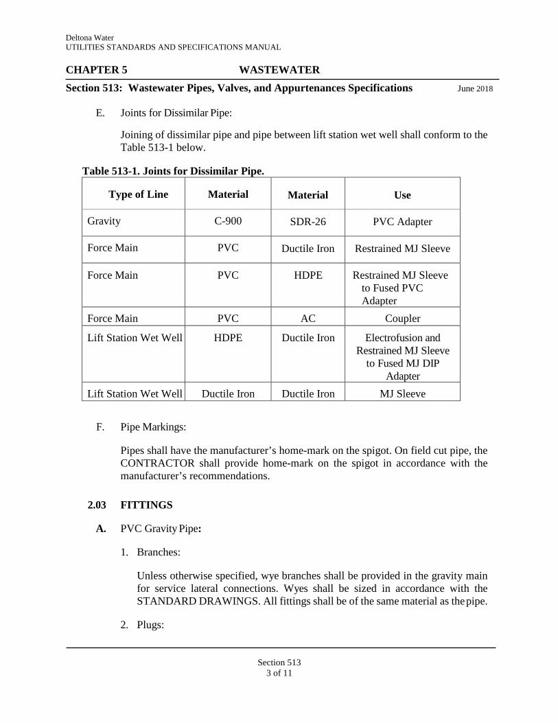
Deltona Water UTILITIES STANDARDS AND SPECIFICATIONS MANUAL CHAPTER 5 WASTEWATER Section 513: Wastewater Pipes, Valves, and Appurtenances Specifications June 2018
Section 513
3 of 11
E. Joints for Dissimilar Pipe:
Joining of dissimilar pipe and pipe between lift station wet well shall conform to the Table 513-1 below.
Table 513-1. Joints for Dissimilar Pipe.
Type of Line Material Material Use
Gravity C-900 SDR-26 PVC Adapter
Force Main PVC Ductile Iron Restrained MJ Sleeve
Force Main PVC HDPE Restrained MJ Sleeve to Fused PVC Adapter
Force Main PVC AC Coupler
Lift Station Wet Well HDPE Ductile Iron Electrofusion and Restrained MJ Sleeve
to Fused MJ DIP Adapter
Lift Station Wet Well Ductile Iron Ductile Iron MJ Sleeve
F. Pipe Markings:
Pipes shall have the manufacturer’s home-mark on the spigot. On field cut pipe, the CONTRACTOR shall provide home-mark on the spigot in accordance with the manufacturer’s recommendations.
2.03 FITTINGS
A. PVC Gravity Pipe:
1. Branches:
Unless otherwise specified, wye branches shall be provided in the gravity main for service lateral connections. Wyes shall be sized in accordance with the STANDARD DRAWINGS. All fittings shall be of the same material as the pipe.
2. Plugs:

Deltona Water UTILITIES STANDARDS AND SPECIFICATIONS MANUAL CHAPTER 5 WASTEWATER Section 513: Wastewater Pipes, Valves, and Appurtenances Specifications June 2018
Section 513
4 of 11
Plugs for stub outs shall be of the same material as the pipe, and gasketed with the same gasket material as the pipe joint, or be of material approved by DELTONA WATER. The plug shall be secured to withstand specified test pressures.
B. PVC Pressure Pipe:
Fittings shall be restrained mechanical joint compact ductile iron fittings that conform to ANSI/AWWA A21.53/C153. Interior and exterior coatings of ductile iron pipe fittings shall be as specified in the appropriate “List of Approved Products”.
C. HDPE Pressure Pipe:
Fittings used with HDPE pipe shall be mechanical joint ductile iron compact fittings in accordance with ANSI/AWWA A21.53/C153 unless otherwise specifically approved by DELTONA WATER. HDPE fittings in wet well shall be in accordance with section 2.04 below.
2.04 DUCTILE IRON PIPE OR HDPE PIPE AND FITTINGS FOR LIFT STATIONS
A. All lift station pipe and fittings from the pump discharge to the first pipe fitting outside of the lift station wet well shall be either all ductile iron with ductile iron flanges in accordance with AWWA C115 or all HDPE piping and HDPE fittings and flanges in accordance with AWWA C906 and C207. All other lift station piping and fittings shall be ductile iron with ductile iron flanges.
1. Ductile Iron Pipe:
Ductile iron pipe of nominal diameter 4 through 64 inches shall conform to ANSI/AWWA A21.51/C151. A minimum of CL 53 pipe shall be supplied for all sizes of pipe unless a higher-class pipe is specifically called out in the PLANS or required by DELTONA WATER.
2. Fittings:
Fittings shall be mechanical joint ductile iron compact fittings in accordance with ANSI/AWWA A21.53/C153.
3. Joints:
Joints shall be flanged conforming to ANSI/AWWA A21.11/C111, unless otherwise called for on the PLANS. Restrained or flanged joints shall be
Deltona Water UTILITIES STANDARDS AND SPECIFICATIONS MANUAL CHAPTER 5 WASTEWATER Section 513: Wastewater Pipes, Valves, and Appurtenances Specifications June 2018
Section 513
5 of 11
provided where called for on the PLANS. Flanged joints shall conform to AWWA C115.
4. Exterior Coatings:
Ductile iron pipe and fittings shall be coated as specified in the appropriate “List of Approved Products”. Primer and field coats shall be compatible and shall be applied in accordance with the manufacturer’s recommendations. Final field coat color shall be green for wastewater.
5. Interior Coatings and Linings:
Ductile iron pipe and fittings shall have an interior protective coating or lining as specified in the appropriate “List of Approved Products”.
6. HDPE Pipe:
HDPE pipe of nominal diameter 4 through 63 inches shall conform to ANSI/AWWA C906 with dimensions conforming to ANSI/AWWA C110/A21.10. A minimum diameter ratio of DR 11 pipe shall be supplied for all sizes of pipe unless a higher-class pipe is specifically called out in the PLANS or required by DELTONA WATER. Vertical piping must be supported at a minimum of 8 feet on center. Spacing may be less if recommended by material manufacturer.
7. HDPE Fittings:
Fittings shall be butt-weld joint HDPE fittings in accordance with ANSI/AWWA C906 and ASTM D3261.
8. HDPE Joints:
Joints with flanges shall be conforming to ANSI/AWWA C207 and ANSI B16.5, unless otherwise called for on the PLANS. Restrained or flanged joints shall be provided where called for on the PLANS. Flanged joints shall be fabricated to mate with ductile iron fittings in accordance with AWWA C115. All flanged joints shall have a backup ring of materials identified in PLANS, either stainless steel or ductile iron. Dimension of ring shall conform to C906 and ANSI B16.5.
2.05 AUTOMATIC AIR RELEASE VALVES
A. General:
Deltona Water UTILITIES STANDARDS AND SPECIFICATIONS MANUAL CHAPTER 5 WASTEWATER Section 513: Wastewater Pipes, Valves, and Appurtenances Specifications June 2018
Section 513
6 of 11
Wastewater force mains shall be equipped with automatic air release or automatic combination air and vacuum release valves, located as shown on the PLANS, and as specified in Section 511 entitled “Wastewater Force Main Standards. Valves shall be located in above ground enclosures as detailed on the STANDARD DRAWINGS.
B. Valve:
The valve body shall be conical in shape and shall be either fusion bonded epoxy coated steel (inside and out) or stainless steel with a funnel shape lower body to automatically drain sewage back into the system. All internal parts shall be corrosion resistant stainless steel or non-metallic plastic materials.
2.06 VALVES
A. General:
In general, plug valves shall not be installed within a force main system, except at wastewater lift stations. Gate valves shall be placed in a vertical position at all other locations within a force main system.
B. Gate Valves:
Refer to Section 410 entitled “Water Main Standards and Specifications”.
C. Plug Valves:
When it is proven by the ENGINEER that it is necessary to install a plug valve within the wastewater transmission system, the following criteria shall apply.
1. Plug valves shall be either eccentric or ballcentric. 2. Plug valves shall be installed complete with operating hand wheels, extension
stems, operator, operating nuts or wrenches as required for normal operation. 3. Valves shall have the name of the manufacturer and the size of the valve cast or
molded onto the valve body. A permanent plate shall be attached to the valve or operator indicating serial number, order number, accessories, operator model and manufacturer, etc.
4. Eccentric plug valves shall be of the non-lubricated type with 80 percent port areas. The port area for valves 4 to 20 inches shall have a minimum 80 percent nominal pipe diameter. Valves 24 inches and larger shall have a minimum port area of 70 percent of nominal pipe diameter.
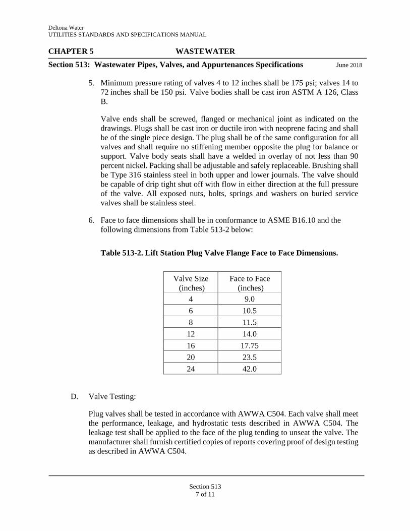
Deltona Water UTILITIES STANDARDS AND SPECIFICATIONS MANUAL CHAPTER 5 WASTEWATER Section 513: Wastewater Pipes, Valves, and Appurtenances Specifications June 2018
Section 513
7 of 11
5. Minimum pressure rating of valves 4 to 12 inches shall be 175 psi; valves 14 to 72 inches shall be 150 psi. Valve bodies shall be cast iron ASTM A 126, Class B.
Valve ends shall be screwed, flanged or mechanical joint as indicated on the drawings. Plugs shall be cast iron or ductile iron with neoprene facing and shall be of the single piece design. The plug shall be of the same configuration for all valves and shall require no stiffening member opposite the plug for balance or support. Valve body seats shall have a welded in overlay of not less than 90 percent nickel. Packing shall be adjustable and safely replaceable. Brushing shall be Type 316 stainless steel in both upper and lower journals. The valve should be capable of drip tight shut off with flow in either direction at the full pressure of the valve. All exposed nuts, bolts, springs and washers on buried service valves shall be stainless steel.
6. Face to face dimensions shall be in conformance to ASME B16.10 and the following dimensions from Table 513-2 below:
Table 513-2. Lift Station Plug Valve Flange Face to Face Dimensions.
Valve Size (inches)
Face to Face (inches)
4 9.0 6 10.5 8 11.5 12 14.0 16 17.75 20 23.5 24 42.0
D. Valve Testing:
Plug valves shall be tested in accordance with AWWA C504. Each valve shall meet the performance, leakage, and hydrostatic tests described in AWWA C504. The leakage test shall be applied to the face of the plug tending to unseat the valve. The manufacturer shall furnish certified copies of reports covering proof of design testing as described in AWWA C504.
Deltona Water UTILITIES STANDARDS AND SPECIFICATIONS MANUAL CHAPTER 5 WASTEWATER Section 513: Wastewater Pipes, Valves, and Appurtenances Specifications June 2018
Section 513
8 of 11
E. Actuators:
Manual valves shall have lever or gear actuators and tee wrenches, extension stems, floor stands, etc. as indicated on the PLANS. All valves 6-inch and larger shall be equipped with gear actuators. All gearing shall be enclosed in a semi-steel housing and be suitable for running in a lubricant with seals provided on all shafts to prevent entry of dirt and water into the actuator. All actuator shafts shall be supported on permanently lubricated bronze bearings. Actuators shall clearly indicate valve position and an adjustable stop shall be provided to set closing torque. All exposed nuts, bolts and washers shall be zinc or cadmium plated. Valve packing adjustment shall be accessible without disassembly of the actuator.
2.07 VALVE BOXES
A. Standard Three-Piece Cast Iron Valve Box:
Three-piece valve boxes are required for mains less than six feet below finished grade as indicated in the STANDARD DRAWINGS. Valve boxes shall be provided with suitable heavy duty ductile or cast-iron bonnets and shall extend to such elevation at or slightly above the finished grade surface as directed by DELTONA WATER. The barrel shall be screw type only and have a 5-1/4-inch shaft. The upper section shall have a flange at the bottom having sufficient bearing area to prevent settling and shall be complete with cast iron covers. Covers shall have “SEWER” cast into the top for all mains.
B. Valve Box Assembly:
Valve box assemblies, as indicated in the STANDARD DRAWINGS, are required for any size main whenever the top of the valve nut is six feet or deeper below the finished surface elevation that is directly above the valve location. Valve boxes shall be one complete assembled unit composed of the ductile or cast-iron valve box with a 5- 1/4-inch barrel shaft and steel extension stem that attaches to the valve body. All moving parts of the extension stem shall be enclosed in a housing to prevent contact with the soil. Valve box assembly shall be adjustable to accommodate variable depths.
C. The stem assembly shall be of a telescoping design that allows for variable adjustment length. The material shall be galvanized square steel tubing. The stem assembly shall have a built-in device that prevents the stem assembly from disengaging at its fully extended length. The extension stem must be capable of surviving a torque test to 1,000 ft-lb without failure.
D. Valve boxes, located in roadways with speed limits above 30 miles per hour or on mains that are 16 inches in diameter or larger, shall have locking lids utilizing a five-

Deltona Water UTILITIES STANDARDS AND SPECIFICATIONS MANUAL CHAPTER 5 WASTEWATER Section 513: Wastewater Pipes, Valves, and Appurtenances Specifications June 2018
Section 513
9 of 11
s i d e d nut with a special wrench needed to open. Valve lids to be made as shown in the STANDARD DRAWINGS.
E. A test station box shall be installed into the valve pad for the placement of the locating wire as shown in the STANDARD DRAWINGS. The test station box shall be as specified in the appropriate “List of Approved Products”.
F. Locating wire shall be 12-gauge single strand solid core copper wire with insulation. The color of the insulation shall be the same color as the color code for the pipe being installed.
G. Each valve marker shall be made of bronze with each specific valve’s information clearly imprinted on its top surface, provided with a hanger pin, and installed in each valve collar as shown in the STANDARD DRAWINGS.
2.08 PRESSURE GAUGES
A. Pressure gauges shall be installed on each lift station discharge pipe as indicated on the STANDARD DRAWINGS. Each pressure gauge shall be direct mounted, diaphragm (type) gauge, stainless steel case, stainless steel sensing element, liquid (oil) filled, with a 4-1/2-inch diameter dial, and furnished with a clear glass crystal window, 1/4-inch shut-off (isolation) valve. Gauges shall be weatherproofed. The face dial shall be white finished aluminum with jet-black graduations and figures. The face dial shall indicate the units of pressure measured in psi, with a zero to 150 psi range.
PART 3 – CONSTRUCTION
3.01 MATERIAL IDENTIFICATION AND TESTING
A. Pipe Identification and Location:
1. Each length of pipe shall bear the name or trademark of the manufacturer, the location of the manufacturing plant and the class or strength classification of the pipe. The markings shall be plainly visible on the pipe barrel. Pipe, which is not clearly marked, is subject to rejection. The CONTRACTOR shall remove all rejected pipe from the project site within five NORMAL WORKING DAYS.
2. All PVC pipe and other pipe that is factory color-coded on the outside surface of the pipe shall be identified and locatable as specified in the STANDARD DRAWINGS. All Ductile Iron Pipe, and other pipe not factory color-coded on the outside surface of the pipe, shall be identified and locatable as specified in the STANDARD DRAWINGS. Where the above type of identification method is not considered to be practical by DELTONA WATER, the pipe shall have a
Deltona Water UTILITIES STANDARDS AND SPECIFICATIONS MANUAL CHAPTER 5 WASTEWATER Section 513: Wastewater Pipes, Valves, and Appurtenances Specifications June 2018
Section 513
10 of 11
field applied three-inch-wide permanent blue paint stripe down the top outside center of the pipe along its entire length.
B. Material Testing Requirements:
1. If requested by DELTONA WATER, a sample of pipe to be tested shall be selected at random by DELTONA WATER or the testing laboratory hired by DELTONA WATER.
2. When the samples tested conform to applicable standards, all pipe represented by such samples shall be considered acceptable based on the test parameters measured. Copies of test reports shall be available before the pipe is installed on the project.
3. In the event that any of the test samples fail to meet the applicable standards, all pipe represented by such tests shall be subjected to rejection. The CONTRACTOR may furnish two additional test samples from the same shipment or delivery, for each sample that failed and the pipe will be considered acceptable if all of these additional samples meet the requirements of the applicable standards. All such retesting shall be at the CONTRACTOR’s expense.
4. Pipe that has been rejected by DELTONA WATER shall be removed from the site of the work by the CONTRACTOR and replaced with pipe that meets these specifications.
3.02 SEPARATION OF MAINS
A. Separation of all mains shall be in accordance with the STANDARD DRAWINGS.
3.03 INSTALLATION OF VALVES
A. All valves shall be inspected upon delivery in the field to insure proper working order before installation. They shall be set and jointed to the pipe in the manner as set forth in the AWWA Standards for the type of connection ends furnished. All valves and appurtenances shall be installed true to alignment and rigidly supported. Any damage to the above items shall be repaired to the satisfaction of DELTONA WATER before they are installed.
3.04 NOTIFICATION OF CONNECTION TO EXISTING MAINS
A. DELTONA WATER shall be notified at least five NORMAL WORKING DAYS in advance to schedule main connections and valve operations. All existing valves are to be operated only by DELTONA WATER. All valves installed are to remain closed during construction.
Deltona Water UTILITIES STANDARDS AND SPECIFICATIONS MANUAL CHAPTER 5 WASTEWATER Section 513: Wastewater Pipes, Valves, and Appurtenances Specifications June 2018
Section 513
11 of 11
B. The CONTRACTOR shall exercise extreme caution when excavating in proximity of DELTONA WATER mains. DELTONA WATER main locations shown on plans are not exact or guaranteed. The CONTRACTOR is responsible for field verifying existing utility locations. DELTONA WATER dispatch operator shall be notified immediately in the event of a force main, water main, or reclaimed water main break or damage. The CONTRACTOR shall immediately repair all damage to DELTONA WATER mains, at the CONTRACTOR’s expense. If the repair is not made in a timely manner, as determined by the DELTONA WATER Inspector, DELTONA WATER may perform repairs and the CONTRACTOR will be charged for repairs.

Deltona Water UTILITIES STANDARDS AND SPECIFICATIONS MANUAL
CHAPTER 5 Section 514:
WASTEWATER Wastewater System Bypass Specifications June 2018
Section 514 1 of 3
PART 1 – GENERAL
1.01 SCOPE OF WORK A. The WORK covered by this Section consists of providing all temporary bypassing to
perform all operations in connection with the flow of wastewater around pipe segment(s) or lift stations. The purpose of bypassing is to prevent wastewater overflows and provide continuous service to all wastewater customers. The CONTRACTOR shall maintain wastewater flow in the construction area in order to prevent backup and/or overflow and provide reliable wastewater service to the users of the wastewater system at all times.
B. When not a low flow scenario or the bypass origination and discharge points are not adjacent to each other, the pipe utilized during the WORK shall be restrained joint DI pipe, restrained joint PVC pipe, fusible PVC pipe with butt welded joints, or HDPE pipe with butt welded joints. Lay flat rolled types hoses may be used when there is a low flow scenario and the bypass origination and discharge points are adjacent to each other. All pipes shall be sufficiently supported in order to restrict horizontal or vertical movement.
PART 2 – PRODUCTS
2.01 GENERAL A. The CONTRACTOR shall provide and maintain adequate equipment, piping, tankers
and other necessary appurtenances in order to maintain continuous and reliable wastewater service in all wastewater lines as required for construction. The CONTRACTOR shall have tankers, backup pump(s), piping and appurtenances ready to deploy immediately.
PART 3 – EXECUTION
3.01 GENERAL A. The CONTRACTOR shall have all materials, equipment and labor necessary to
complete the repair, replacement or rehabilitation on the job site prior to isolating the gravity main segment, manhole, or lift station. The CONTRACTOR shall demonstrate that the pumping system is in good working order and is sufficiently sized to successfully handle flows by performing a test run for a period of 24-hours prior to beginning the WORK.
3.02 TRAFFIC CONSIDERATIONS
A. The CONTRACTOR shall locate bypass pumping suction and discharge lines so as to not cause undue interference with the use of streets, private driveways and alleys to include the possible temporary trenching of piping at critical intersections. Ingress and egress to adjacent properties shall be maintained at all times. Ramps, steel plates or other methods shall be deployed by the CONTRACTOR to facilitate traffic over surface piping. High traffic commercial properties may require alternate methods.
Deltona Water UTILITIES STANDARDS AND SPECIFICATIONS MANUAL
CHAPTER 5 Section 514:
WASTEWATER Wastewater System Bypass Specifications June 2018
Section 514 2 of 3
3.03 BYPASS PLAN A. The CONTRACTOR shall submit a sufficiently detailed drawing or comprehensive
written plan to DELTONA WATER for approval and acceptance that describes the intended bypass for the maintenance of flows during construction. The CONTRACTOR shall also provide a sketch with the written plan showing the location of bypass pumping equipment for each lift station or line segment(s) around which flows are being bypassed. The plan shall include any proposed tanker(s), pump(s), bypass piping, backup plan, and equipment, work schedule, monitoring log for bypass pumping, monitoring plan of the bypass pumping operation and maintenance of traffic plan. The CONTRACTOR shall cease bypass operations and return flows to the new and/or existing sewer when directed by DELTONA WATER. All bypass piping shall be designed to withstand at least twice the maximum system pressure or a minimum of 50 psi, whichever is greater. During bypassing, no wastewater shall be leaked, dumped, or spilled in or onto, any area outside of the existing wastewater system. When bypass operations are complete, all bypass piping shall be drained into the wastewater system prior to disassembly.
3.04 BYPASS OPERATION
A. DELTONA WATER must approve of and accept the bypass plan for planned bypasses prior to implementation of the bypass. The CONTRACTOR shall plug off and pump down the sewer manhole or line segment in the immediate WORK area and shall maintain the wastewater system so that surcharging does not occur. Emergency bypasses shall be as directed by DELTONA WATER.
B. Where WORK requires the line to be blocked beyond NORMAL WORKING HOURS and bypass pumping is being utilized, the CONTRACTOR shall be responsible for monitoring the bypass operation 24 hours per day, 7 days per week. If accepted in the bypass plan by DELTONA WATER, any electronic monitoring in lieu of on-site monitoring must be detailed in the written plan and approved by DELTONA WATER.
C. The CONTRACTOR shall ensure that no damage will be caused to private property as a result of bypass pumping operations. The CONTRACTOR shall complete the WORK as quickly as possible and satisfactorily pass all tests, inspections and repair all deficiencies prior to discontinuing bypassing operations and returning flow to the sewer manhole or line segment.
D. The CONTRACTOR shall immediately notify DELTONA WATER should a sanitary sewer overflow occur and take the necessary action to clean up and disinfect the spillage to the satisfaction of DELTONA WATER and/or other governmental agency. If sewage is spilled onto public or private property, the CONTRACTOR shall wash down, clean up and disinfect the spillage to the satisfaction of DELTONA WATER and/or other governmental agency. When bypassing a lift station, one back-up pump equal to the primary unit shall be required. Bypass pumps shall have a maximum rating of 65 decibels for sound attenuation next to residential developments, 70 decibels next to commercial
Deltona Water UTILITIES STANDARDS AND SPECIFICATIONS MANUAL
CHAPTER 5 Section 514:
WASTEWATER Wastewater System Bypass Specifications June 2018
Section 514 3 of 3
businesses, and 80 decibels next to industrial areas or in accordance with the LAND DEVELOPMENT CODE.
3.05 CONTRACTOR LIABILITY
A. The CONTRACTOR shall be responsible for all required pumping, equipment, piping and appurtenances to accomplish the bypass and for any and all damage that results directly or indirectly from the bypass pumping equipment, piping and/or appurtenances. The CONTRACTOR shall also be liable for all CITY personnel and equipment costs, penalties, and fines resulting from sanitary sewer overflows. It is the intent of these specifications to require the CONTRACTOR to establish adequate bypass pumping as required regardless of the flow condition.

Section 515 1 of 4
Deltona Water UTILITIES STANDARDS AND SPECIFICATIONS MANUAL CHAPTER 5 WASTEWATER
Section 515: Submersible Wastewater Pumps Specifications June 2018
PART 1 – GENERAL
1.01 SCOPE OF WORK
A. The specifications within this Section are for equipment that is intended to be standard pumping equipment of proven ability as manufactured by a reputable firm having at least five years’ experience in the production of such equipment. The equipment furnished shall be designed, constructed and installed in accordance with the best practices and methods and shall operate satisfactorily when installed as shown on the PLANS.
B. All parts shall be so designed and proportioned as to have liberal strength and stiffness and to be especially adapted for the WORK to be done. Ample space shall be provided for inspection, repairs and adjustment. All necessary foundation bolts, plates, nuts, and washers shall be furnished by the equipment manufacturer and shall be of Type 316 stainless steel. Brass or stainless steel nameplates identifying the name of the manufacturer, voltage, phase, rated horsepower, speed and any other pertinent data shall be attached to each pump. The nameplate rating of the motors shall not be exceeded.
C. The pumps shall be capable of handling raw unscreened domestic wastewater and minimum 3-inch diameter solid spheres. Pumps shall be mounted in the wet well as shown in the STANDARD DRAWINGS. Refer to the appropriate “List of Approved Products”.
1.03 QUALITY ASSURANCE
A. Warranty/Service Center shall be located in Orange, Lake, Hillsborough, Volusia, or Seminole Counties and service response shall be within two hours during NORMAL WORKING HOURS, and provide emergency service 24-hours/7-days a week.
B. Vendor shall have an exchange program in place with ability to exchange out-of- service pumps that require shop work for pump in vendor stock until repairs are complete or serviceable pump is available.
PART 2 – PRODUCTS
2.01 PUMP CONSTRUCTION DETAILS
A. Shaft:
The pump shaft shall be of Series 300 or 400 stainless steel or carbon steel. When a carbon steel shaft is provided, the manufacturer shall demonstrate that any part of the shaft which will normally come in contact with the wastewater has proven to be corrosion resistant in this application. The shaft and bearings shall be adequately designed to meet the maximum torque required for any start-up or operating condition and to minimize vibration and shaft deflection. As a minimum, the pump shaft shall rotate on two permanently lubricated bearings. The upper bearing shall be a single row ball bearing. The lower bearing shall be a two-row angular contact ball bearing, if required to minimize vibration and provide maximum bearing life. Bearings shall be
Section 515 2 of 4
Deltona Water UTILITIES STANDARDS AND SPECIFICATIONS MANUAL CHAPTER 5 WASTEWATER
Section 515: Submersible Wastewater Pumps Specifications June 2018
designed to provide a minimum life of 50,000 hours.
B. Impeller: The impeller shall be constructed of bronze or gray cast iron, ASTM A-48, class 30. All external bolts and nuts shall be of Type 316 stainless steel. Each pump shall be provided with a replaceable metallic wear ring system to maintain pump efficiency. As a minimum one stationary wear ring provided in the pump volute and one rotating wear ring provided on the pump impeller shall be required. A two-part system is acceptable. The closed type can be single or double vaned. The open type shall be single vane with a self-cleaning, adjustable cast iron wear plate. All impellers shall be non-clogging and dynamically balanced.
C. Mechanical Seal: Each pump shall be provided with a tandem double mechanical seal or dual mechanical seals running in an oil reservoir, composed of two separate lapped face seals, each consisting of one stationary and one rotating tungsten carbide ring with each pair held in contact by a separate spring, so that the outside pressure assists spring compression in preventing the seal faces from opening. The compression spring shall be protected against exposure to the pumped liquid. Silicone carbide may be used in place of tungsten carbide for the lower seal. The pumped liquid shall be sealed from the oil reservoir by one face seal and the oil reservoir from the air-filled motor chamber by the other. The seals shall require neither maintenance nor adjustment, and shall be easily replaced. Seal shall be held in place by locking ring. Conventional double mechanical seals with a single spring between the rotating faces, requiring constant differential pressure to effect sealing and subject to openings and penetration by pumping forces, shall not be considered equal to tandem seal specified and required. Cartridge seal shall be acceptable.
D. Guides: A sliding guide bracket shall be an integral part of the pump casing and shall have a machined connecting flange to connect with the cast iron discharge connection (pump base elbow), which shall be bolted to the floor of the wet well with stainless steel anchor bolts and so designed as to receive the pump discharge flange without the need of any bolts or nuts. The pump base elbow design shall be interchangeable such that it will provide a watertight connection for any of the specified or otherwise accepted pumps without requiring any special tools, gaskets or adapters. Sealing of the pumps to the discharge connection shall be accomplished by a simple linear downward motion of the pump with the entire weight of the pumping unit guided by two Type 316 seamless tubular stainless steel guides which will press it tightly against the discharge connection. No brackets for guide rail system will be mounted to discharge piping. No portion of the pump shall bear directly on the floor of the wet well and no rotary motion of the pump shall be required for sealing. Sealing at the discharge connection by means of a diaphragm or similar method of sealing will not be accepted as an equal to a metal to metal contact of the pump discharge and mating discharge connection specified and required. Approved pump manufacturers, if necessary to meet the above specification, shall provide a sliding guide bracket adapter. No reducing brackets or adapters shall be placed on or between the base

Section 515 3 of 4
Deltona Water UTILITIES STANDARDS AND SPECIFICATIONS MANUAL CHAPTER 5 WASTEWATER
Section 515: Submersible Wastewater Pumps Specifications June 2018
elbow seating surface and pump volute. The design shall be such that the pumps shall be automatically connected to the discharge piping when lowered into place on the discharge connection. The pumps shall be easily removable for inspection or service, requiring no bolts, nuts or fastenings to be removed for this purpose and no need for personnel to enter the wet well.
2.02 MOTORS
A. General Requirements: All motors shall be built in accordance with latest NEMA, IEEE, ANSI and AFBMA standards where applicable. Pump motors shall be housed in an air-filled, watertight casing and shall have Class F insulated windings which shall be moisture resistant. Motors shall be NEMA Design B, rated 155 degrees C maximum. Pump motors shall have cooling characteristics suitable to permit continuous operation, in a totally, partially or non-submerged condition. The pump shall be capable of running continuously in a non-submerged condition under full load without damage, for extended periods. The motor shall be capable of a minimum of 10 starts per hour. A field running test demonstrating this ability, with 24-hours of continuous operation under the above conditions, shall be performed for all pumps being supplied before final acceptance, as required by DELTONA WATER. Pump motors shall be non-overloading over entire pump range.
1) Motors 25 horsepower and below shall be rated 230/460-volt, 3-phase.
2) Motors greater than 25 horsepower shall be rated 460-volt, 3-phase.
B. Heat and Moisture Sensors: Each motor shall incorporate a minimum of one ambient temperature compensated overheat sensing device and one moisture sensing device. These protective devices shall be wired into the pump controls in such a way that if excessive temperature is detected the pump will shut down. If moisture is detected, a fault will be sent to SCADA and activate a seal failure alarm light on the dead front door without affecting pump operation. These devices shall be self-resetting.
C. Cables: Cables shall be designed specifically for submersible pump applications and shall be properly sealed. A type CGB watertight connector with a neoprene gland shall be furnished with each pump to seal the cable entry at the top of the pump. The pump cable entry seal design shall preclude specific torque requirements to insure a watertight and submersible seal. The cable entry shall be comprised of a single cylindrical elastomer grommet, flanked by washers and/or a compression gland, all having a close tolerance fit against the cable outside diameter and the entry inside diameter and compressed by the entry body containing a strain relief function, separate from the function of sealing the cable. The assembly shall bear against a shoulder in the pump top. The cable entry junction chamber and motor shall be separated by a stator lead sealing gland, epoxy barrier, or terminal board, which shall isolate the

Section 515 4 of 4
Deltona Water UTILITIES STANDARDS AND SPECIFICATIONS MANUAL CHAPTER 5 WASTEWATER
Section 515: Submersible Wastewater Pumps Specifications June 2018
motor interior from foreign material gaining access through the pump top. Secondary sealing systems utilizing epoxy potting compounds may be used. The manufacturers shall supply a cable cap as part of the spare parts for each pump when this type of sealing system is used. All cables shall be continuous, without splices from the motor to the control panel, junction box terminal strip, unless otherwise approved by DELTONA WATER. The junction chamber, containing the terminal board, shall be perfectly leak proof.
2.03 PUMP CONTROL SYSTEM
A. Refer to Section 516 entitled “Wastewater Lift Station Electrical Specifications”. PART 3 – EXECUTION
3.01 SHOP PAINTING A. Before exposure to weather and prior to shop painting, all surfaces shall be thoroughly
cleaned, dry and free from all mill-scale, rust, grease, dirt and other foreign matter. All pumps and motors shall be shop coated with a corrosion resistant paint proven to withstand an environment of raw wastewater. All nameplates shall be properly protected during painting.
B. Gears, bearing surfaces, and other similar surfaces obviously not to be painted shall be given a heavy shop coat of grease or other suitable rust-resistant coating. This coating shall be maintained as necessary to prevent corrosion during periods of storage and erection and shall be satisfactory to DELTONA WATER up to the time of the final acceptance test.
3.02 HANDLING
A. All parts and equipment shall be properly protected so that no damage or deterioration will occur during a prolonged delay from the time of shipment until installation is completed and the units and equipment are ready for operation. Finished surfaces of all exposed pump openings shall be protected by wooded planks, strongly built and securely bolted thereto. Finished iron or steel surfaces not painted shall be properly protected to prevent rust and corrosion.
3.03 WARRANTY
A. The pump manufacturer shall warrant the units being supplied to DELTONA WATER against defects in workmanship and material for a period of 5-years from installation or 10,000 hours from installation, whichever comes first.
3.04 TOOLS AND SPARE PARTS
A. No tools or spare parts shall be required.
Deltona Water UTILITIES STANDARDS AND SPECIFICATIONS MANUAL CHAPTER 5 WASTEWATER
Section 516: Wastewater Lift Station Electrical System Specifications June 2018
Section 516
1 of 27
PART 1 – GENERAL
1.01 SCOPE OF WORK
A. This Section specifies the electrical system requirements for wastewater lift stations. These requirements apply to standard lift stations and also include general requirements applying to stations with Variable Frequency Drives (VFDs) and Motor Control Centers (MCCs). Provide all work necessary for a complete and operational lift station installation.
B. All work shall be performed in accordance with the current revision of the National Fire Protection Association (NFPA) 70, National Electrical Code (NEC) and OSHA regulations and guidelines. Provide equipment labeled or listed by a nationally recognized testing laboratory or other organization as a basis for approval under the NEC.
C. Pump Operation shall be controlled automatically by means of hydrostatic pressure transducer level sensors with a float ball backup system for alarms. VFD pump operation transducer shall be PID-controlled to maintain a level set point in the wet well. Pumps shall start and stop based on specific level set points.
D. The Lift Station control panel shall respond to liquid level float switches and other approved methods, specified in the “List of Approved Products”, to automatically start and stop pumps as well as sound an alarm upon high or low wet well levels. Control switches shall provide means to operate each pump manually or automatically. When operated in the automatic mode, the control assembly shall provide means to manually select or automatically alternate the position of the “lead” and “lag” pumps for each pumping cycle. A float type liquid level control system shall continuously monitor wet well liquid level and control operation of the low-level cutoff for the pumps and shall operate off a 24-VAC.
E. The control panel shall operate a minimum of two electrical submersible pumps
at the power characteristics stipulated. The control function shall provide for the operation of the lead pump under normal conditions. If the incoming flow exceeds the pumping capacity of the lead pump, the lag pump shall automatically start to handle this increased flow. As the flow decreases, pumps shall be cut off at the elevation as shown on the PLANS. Pumps shall alternate positions as lead pump at the end of each cycle. A failure of the alternator shall not disable the pumping system. The alternator shall include a safe, convenient method of manual alternation and also have provisions to prevent automatic alternation without disturbing any wiring. Should the “pump off” regulator fail, the system shall keep the station in operation.
Deltona Water UTILITIES STANDARDS AND SPECIFICATIONS MANUAL CHAPTER 5 WASTEWATER
Section 516: Wastewater Lift Station Electrical System Specifications June 2018
Section 516
2 of 27
F. Lift station control panel(s) shall be provided for each wastewater lift station. Refer to Chapter 7 entitled “SCADA and Control Panel Specifications” for requirements related to lift station control and monitoring and control panel construction and materials.
PART 2 – PRODUCTS
2.01 GENERAL
A. Provide products and materials as specified in the appropriate “List of Approved Products” and as specified herein. Provide products of the same or similar type of one manufacturer in order to achieve standardization.
B. Equipment and devices installed outdoors shall be capable of continuous operation within a minimum ambient temperature range of minus 22 degrees F to 144 degrees F unless noted otherwise.
C. Provide manufacturer’s standard finish except where specific color or finish is indicated.
2.02 POWER SUPPLY AND MAIN DISCONNECT
A. Coordinate installation of all new and modified power services with the local utility and obtain all required permits.
B. Power supply to the control panel shall be 240-volt, 3-phase, 4-wire (Delta) or 480- volt, 3-phase, 4-wire (Wye). Service shall be designed for the station full load amperes including the loading of any planned future equipment plus a minimum 50% spare capacity. Single-phase power is not permitted.
C. The power supply cables to the control panel from the off-site source shall be installed underground within a minimum 3-inch diameter schedule 80 PVC electrical conduit and in accordance with the NEC.
D. For systems having a permanently mounted standby generator, refer to Section 516 Part 2.07 “Standby Power Generator System” for generator and transfer switch requirements.
E. Systems requiring a portable generator connection shall meet the following requirements:
1. Coordinate requirements with control panel supplier to ensure the appropriate transfer mechanisms, breakers, and generator receptacle are provided based on the selection of service entrance equipment.
2. Provide a breaker based UL1008 listed and service entrance rated transfer
Deltona Water UTILITIES STANDARDS AND SPECIFICATIONS MANUAL CHAPTER 5 WASTEWATER
Section 516: Wastewater Lift Station Electrical System Specifications June 2018
Section 516
3 of 27
switch with generator cam-lock connectors to be used as the service entrance equipment and terminate utility feed to this device. Refer to Manual Transfer Switch (MTS) specification for requirements.
3. At the option of the Contractor, a generator receptacle with appropriately interlocked breakers in the control panel and externally mounted breaker-based service entrance rated disconnect switch may be used in lieu of the above transfer switch. A separately mounted service entrance rated breaker type main disconnect shall be provided to terminate utility power outside of the control panel. The service entrance rated breaker type disconnect shall be rated for 100A minimum and be of NEMA 4X construction. A main circuit breaker and generator breaker with mechanical interlock and generator receptacle shall be installed in the control panel for manual switching between utility and generator power. Coordinate all requirements with the control panel supplier.
F. Manual Transfer Switch:
1. Provide service entrance rated UL 1008 listed manual transfer switch for lift stations requiring portable generator systems.
2. Transfer switch shall be molded case breaker-based with safety interlocked door and interior dead-front panel construction. Transfer switch enclosure shall be NEMA 3R 304 Stainless Steel construction powder coated white.
3. Switches shall be 240V or 480V AC 3-phase, 4-wire based on available site voltage and rated for a minimum of 100A. Provide with color coded cam-lock style connectors as required for the site specific amperage having a minimum 400A rating.
4. Provide local indication of utility power available and utility power status dry contact for connection to the control panel.
5. Manufacturer: ESL Power Systems Stormswitch, or approved equal.
G. On all 480-volt systems, an additional UL listed, NEMA 3R, lockable, non-fused, safety type switch utility service disconnect shall be installed ahead of the utility meter in accordance with local utility requirements. The disconnect shall be rated for the maximum available fault current from the utility serving the lift station.
H. Provide 3-phase surge suppression on the downstream side of the transfer switch to provide surge protection on both utility and generator power. A Surge Protective Device (SPD) shall be included and wired to protect motors and control
Deltona Water UTILITIES STANDARDS AND SPECIFICATIONS MANUAL CHAPTER 5 WASTEWATER
Section 516: Wastewater Lift Station Electrical System Specifications June 2018
Section 516
4 of 27
equipment from induced line surges. All SPD’s shall be UL listed and installed in accordance with the respective power company requirements and manufacturer’s specifications. SPD’s shall be attached to the load side of the main transfer switch and mounted in a separate NEMA 4X enclosure directly attached to the transfer switch enclosure. Where a manual transfer switch is not supplied, SPD’s shall be installed downstream of the control panel main and generator breakers and mounted external to the control panel. SPD’s shall meet the following minimum requirements:
1. The SPD unit shall be UL listed and labeled as per UL 1449 latest edition and have a UL 1283 listing for active sine wave tracking.
2. The unit shall meet “Testing Requirements” of IEEE 62.41 and 62.45.
3. Minimum 10-year replacement warranty.
4. Provide with Disconnect Only option.
5. Provide status indicator lights and contact relay output indicating suppressor fault.
2.03 BOXES
A. Outlet and Device Boxes:
1. General: Outlet and device boxes shall be cast aluminum with a powder coat finish and threaded outlets. The boxes shall be gasketed, weatherproof, and UL listed for wet locations. Provide with matching gasketed weatherproof covers selected for the appropriate application.
2. All receptacles and switches shall be industrial grade as manufactured by Eaton/Cooper, Hubbell, or Leviton.
3. For wet location receptacles, provide die-cast powder coated aluminum impact- resistant, single-gang outlet cover with a NEMA 3R rating while in-use.
4. For wet location switches, provide gasketed powder coated aluminum covers with hinge.
B. Terminal Junction Boxes (Hazardous Locations):
1. Terminal junction boxes for hazardous locations shall be provided for all junction boxes having a direct connection to the lift station wet well where there is not an appropriate listed conduit seal-off or air gap in between.
Deltona Water UTILITIES STANDARDS AND SPECIFICATIONS MANUAL CHAPTER 5 WASTEWATER
Section 516: Wastewater Lift Station Electrical System Specifications June 2018
Section 516
5 of 27
2. Provide an ATEX or equivalently approved Type Ex e Class I Zone 1 terminal junction box having UL Listed NEMA 4X Type 304 stainless steel construction for termination of wet well power and control wiring. Power and control wiring shall be separated by a minimum of 12-inches. Separate power and control wiring junction boxes may be provided. The box shall be provided with corrosion resistant terminal strips to accommodate instrumentation and power conductors from the wet well. Seal conduits entering the junction box from the wet well with duct seal, or equivalent, and provide a minimum Class I Division 2 poured conduit seal between the junction box and control panel.
3. Junction Box: Hoffman Zonex ATEX certified Type 4X, or approved equal.
4. Terminal Block: Eaton XB series, Phoenix Contact UT series, or approved equal Ex e labeled corrosion resistant screw type terminal block.
C. Terminal Junction Boxes (Non-Hazardous Locations):
1. General: Provide terminal junction boxes as required.
2. Terminal junction boxes shall be NEMA 4X Type 304 Stainless Steel with hinged cover and white enamel painted interior mounting panel.
D. Concrete electrical box:
1. General: Provide concrete electrical boxes as required for underground electrical circuits.
2. Concrete electrical boxes shall be sized as required, have H/20 loading capacity and shall be reinforced concrete with extension and open bottom with openings in each end for conduit entry. Covers shall be galvanized steel diamond plate with integral handle with appropriate label/marking and locking bolts.
3. Manufacturer: Oldcastle/Christy B series or approved equal.
2.04 CONDUIT AND FITTINGS
A. Rigid Aluminum Conduit:
1. Provide rigid aluminum conduit above grade and where conduit sealing fittings are used. Provide aluminum sealing fittings to prevent galvanic corrosion and seizing of threaded connections. Use with stainless steel Myers hub for connections to enclosures. Provide PVC-coated conduit or coat aluminum with bitumastic where in contact with concrete.
Deltona Water UTILITIES STANDARDS AND SPECIFICATIONS MANUAL CHAPTER 5 WASTEWATER
Section 516: Wastewater Lift Station Electrical System Specifications June 2018
Section 516
6 of 27
2. Rigid aluminum conduit shall meet requirements of NEMA C80.5 and UL6A and be of Type 6063 copper-free aluminum alloy.
B. PVC Schedule 80 Conduit:
1. Provide PVC Schedule 80 conduit below grade. PVC conduit may be extended from below to above grade where conduit sealing fittings are not required such as from the wet well to the terminal junction box.
2. PVC Schedule 80 conduit shall meet the requirements of NEMA TC-2 and UL 651 and shall be furnished without factory formed bell.
C. Flexible Metal Liquid-tight Conduit:
1. Provide flexible metal liquid-tight conduit where necessary to provide flexible connections for instrument and equipment connections.
2. Flexible metal liquid-tight conduit shall meet the requirements of UL 360 and be constructed of galvanized steel with an extruded PVC jacket.
D. Fittings:
1. Rigid aluminum fittings shall meet the requirement of UL 514B and be of copper- free construction.
2. PVC fittings shall meet the requirements of NEMA TC-3.
2.05 ALARM LIGHT, HIGH LEVEL
A. A vapor proof and vandal proof screw-on type red alarm light shall be mounted on top of a separate 1½-inch minimum diameter Schedule 40 aluminum riser pole located behind and connected to the bottom of the panel by a 1½-inch minimum diameter water tight flexible electrical conduit. The riser pole shall be secured to the horizontal cross member struts, not the panel, with the bottom of the light being no less than 12-inches but not more than 18-inches above the top of the enclosure.
B. Alarm Light Specification:
1. Type: Rotating reflector or flashing bulb.
2. Dome: Polycarbonate.
3. Color: Red.
4. Enclosure: NEMA 4X with ½-inch threaded pipe fitting.
Deltona Water UTILITIES STANDARDS AND SPECIFICATIONS MANUAL CHAPTER 5 WASTEWATER
Section 516: Wastewater Lift Station Electrical System Specifications June 2018
Section 516
7 of 27
5. UL Listed.
6. Power: 24Vdc.
2.06 ELECTRICAL EQUIPMENT RACK
A. The main support beams shall be minimum 6-inch structural aluminum I-Beams or H-Beams with a minimum web thickness of 0.210-inches. Two coats of bitumastic coating shall be applied where aluminum will be in contact with concrete or the ground.
B. Horizontal cross member struts shall be 12-gauge stainless steel U-channels with a minimum nominal dimension of 1-1/2-inch by 1-inch. The ENGINEER shall review the structure’s wind loading requirements and make any size increases to the main support posts as needed. All other electrical equipment support brackets and hardware shall be 316-stainless steel. Hardware shall include, as a minimum, brackets, nuts, bolts, washers, toggle bolts, clamps, straps, etc.
C. An outdoor rated weatherproof GFCI receptacle, UL listed for wet locations, shall be mounted on the electrical equipment rack with NEMA 3R while-in-use aluminum cover. The receptacle shall be fed from a dedicated circuit.
2.07 STANDBY POWER GENERATOR SYSTEM
A. General:
1. A stationary standby power generator system including the diesel engine generator and automatic transfer switch shall be installed at lift stations, as required by Section 512 entitled “Wastewater Lift Station Standards and Specifications”.
2. The generator shall be sized to carry the full lift station load with all pumps operating. Operating voltage shall match of the lift station utility source.
3. Generator configuration shall be diesel engine in a weatherproof sound attenuated enclosure with a diesel fuel tank(s) and separately mounted automatic transfer switch.
B. Generator Set:
1. Generator Set shall be a UL 2200 listed package.
2. The generator set shall consist of a diesel engine directly coupled to an electric generator, together with the necessary controls and accessories to provide continuous electric power to the lift station for a minimum
Deltona Water UTILITIES STANDARDS AND SPECIFICATIONS MANUAL CHAPTER 5 WASTEWATER
Section 516: Wastewater Lift Station Electrical System Specifications June 2018
Section 516
8 of 27
duration of 48-hour failure of the normal power supply. The main fuel tank shall have at least 133 percent of the amount of fuel required for the class rating (Class 48), as defined in NFPA 110. The generator set shall be sized to operate continually for the minimum run time of 48-hours under a full load condition.
3. A complete engine generator system shall be furnished and installed with fuel transfer pump, fuel tank, day tank with rupture basin (where required), battery, battery charger, muffler, radiator, control panel, remotely mounted automatic transfer switch, and all other accessories required for an operational system. All materials and parts of the generator set shall be new and unused. Each component shall be of current manufacture from a firm regularly engaged in the production of such equipment. The set shall be of a standard model in regular production at the manufacturer’s place of business.
C. Requirements:
1. The emergency generator set and accessories shall be of a type that complies with the latest edition of the NEC and all applicable state and local building codes.
2. The material and workmanship used in the manufacture of this equipment shall be of the highest quality consistent with the current standards for like equipment, and the equipment shall be manufactured in such a manner so as to conform to the latest applicable IEEE, ANSI, ISA, and NEMA standards.
D. Engine:
1. The engine shall be water-cooled, four-stroke cycle, compression ignition diesel. The engine shall be equipped with a fuel filter with a replaceable spin-on canister, lube oil and intake air filters, lube oil and fuel coolers, a fuel transfer pump, fuel priming pump, and a jacket water cooling system consisting of jacket water pump, fan assembly, fan guard, and duct flange outlet.
2. The engine and generator shall be torsionally compatible to prevent damage to either engine or generator. An engine instrument panel shall be installed on the generator set in an approved location. The panel shall include oil and fuel pressure and water temperature gauges. A mechanically driven engine hour meter shall also be provided.
3. The engine governor shall be of the isochronous electronic type. Frequency regulation shall not exceed plus/minus 0.25 percent under

Deltona Water UTILITIES STANDARDS AND SPECIFICATIONS MANUAL CHAPTER 5 WASTEWATER
Section 516: Wastewater Lift Station Electrical System Specifications June 2018
Section 516
9 of 27
steady state conditions. The engine shall start and assume its rated load within 10 seconds, including transfer time.
E. Generator:
1. The generator shall be a three-phase, 60-Hz, single bearing, synchronous type, built to NEMA Standards. Epoxy impregnated Class F insulation shall be used on the stator and the rotor.
2. The excitation system shall employ a generator-mounted volt per Hz type regulator. Voltage regulation shall be plus/minus two percent from no load to full load. Readily accessible voltage drop, voltage level and voltage gain controls shall be provided. Voltage level adjustment shall be a minimum of plus/minus five percent.
F. Engine Generator Control Panel:
Control panel shall be mounted inside generator enclosure. Panel shall contain, but not be limited to, the following equipment:
1. Control Equipment:
a. Control equipment shall consist of all necessary exciter control equipment, generator voltage regulators, voltage-adjusting rheostat, and speed control equipment and automatic starting controls, as required to satisfactorily control the engine/generator set. In addition, an automatic safety shut down shall be provided for low oil pressure and/or high temperature conditions in the engine. An emergency shut down lever switch shall be provided on the air intake. Provide a minimum of twelve form “C” auxiliary contacts for generator run and generator failure for connection to SCADA. All LCD screens exposed to the sun shall have an aluminum sunshield painted white with hinged flap covering the screen surrounding the manufacturer’s enclosure.
2. Metering Equipment:
a. Metering equipment shall include 3-1/2-inch meters (dial or digital type frequency meter, two percent accuracy voltmeter, and ammeter and ammeter-voltmeter phase selector switch). The control panel shall also include the engine water temperature, lube oil pressure and hour meter.
3. Fault Indicators:
b. Individual press-to-test fault indicator lights for low oil pressure,

Deltona Water UTILITIES STANDARDS AND SPECIFICATIONS MANUAL CHAPTER 5 WASTEWATER
Section 516: Wastewater Lift Station Electrical System Specifications June 2018
Section 516
10 of 27
high water temperature, low water level, over speed, and over crank shall be provided.
4. Function Switch:
a. A four-position function switch marked “Auto”, “Manual”, “Off/Reset”, and “Stop” shall be provided.
G. Battery Charger:
The battery charger shall be UL 1236 listed and designed that it shall not be damaged and shall not trip its circuit protective device during engine cranking or it shall be automatically disconnected from battery during cranking period. The charger shall be mounted inside the emergency generator enclosure. The charger shall have a 7-day/24-hour timer control. The charger shall include an ammeter and voltmeter, Power ON pilot light, AC failure relay and light, and a low and high DC voltage alarm and relay.
H. Battery:
The battery shall be lead-acid type with sufficient capacity to provide 90 seconds total cranking time without recharging. The battery shall be adequately rated for the specific generator set. The battery shall be encased in hard rubber or plastic, shall be housed in an acid resistant frame, and shall be furnished with proper cables and connectors, together with rack and standard maintenance accessories.
I. Base Mounting:
A suitable number of spring-type vibration isolators with a noise isolation pad shall be provided to support the set and its liquids. Isolators shall be bolted to concrete generator pad.
J. Electrical Connections:
All connections to the generator set shall be underground.
K. Cooling System:
The generator set shall be equipped with an engine-mounted radiator sized to maintain safe operation at 110 degrees Fahrenheit maximum ambient temperature. A blower type fan shall be used directing the airflow from the engine through the radiator. The motor shall be equipped with a crankcase heater. The entire cooling system shall be filled with 50 percent glycol-water solution.
Deltona Water UTILITIES STANDARDS AND SPECIFICATIONS MANUAL CHAPTER 5 WASTEWATER
Section 516: Wastewater Lift Station Electrical System Specifications June 2018
Section 516
11 of 27
L. Fuel System:
1. Regulated Tanks - a fuel tank that has a capacity greater than 550 gallons.
a. Regulated tanks are subject to F.A.C. 62.762 and must have registration submitted and insurance in place. Both registration and monthly visual inspection reports shall be kept on site and readily available for review by the Federal Department of Environmental Protection (FDEP) and/or the Volusia County Health Department (VCHD). Any tank installation that is greater than 1,320 gallons shall have a Spill Prevention, Control, and Countermeasure Plan (SPCC) completed by the Engineer of Record prior to installation and registration as per Title 40 Code of Federal Regulations (CFR), Part 112. Tanks shall have a 1993 sticker and content “diesel” label located in a conspicuous location that can be seen by anyone approaching the tank for inspection or fueling.
2. Non-Regulated Tanks - a fuel tank that has a capacity of less than 550 gallons.
a. Non-regulated tanks do not require registration or insurance and will be visually inspected quarterly and shall have a 1993, “Less than 550 Gallons” sticker and a content “diesel” label applied to the tank in a conspicuous location that can be seen by anyone approaching the tank for inspection or fueling.
3. Fuel Storage Tank:
a. All fuel tanks shall be double wall steel or steel and concrete tanks with an interstitial annular space.
b. Provide fuel tanks sized as required for 48-hours of continuous runtime.
c. Two fuels tanks in series is the maximum allowed at any one facility.
d. Fuel tanks requiring a day tank for the generator shall include a rupture basin for the day tank.
e. All fuel lines shall be installed above ground with a concrete pad separating the piping from the ground. The piping will be secured to the concrete every five feet to avoid vibration. The pipe shall be black iron with threaded ends. Pipe dope shall be used at all connections. No thread tape shall be used. Underground piping is prohibited for the fuel delivery system.
Deltona Water UTILITIES STANDARDS AND SPECIFICATIONS MANUAL CHAPTER 5 WASTEWATER
Section 516: Wastewater Lift Station Electrical System Specifications June 2018
Section 516
12 of 27
f. All external tanks (non-belly tanks) shall have hurricane tie downs.
g. Provide audible alarm when liquid level in tank reaches 90 percent of the capacity.
h. Non-regulated tanks may have visual leak detection.
i. Regulated tanks shall be equipped with the following fuel monitoring system:
1) Fuel tank level control panel for tank gauging, leak sensing, and audible/visual alarm annunciation. Panel shall be NEMA 4X construction.
2) Provide 4-20mA output proportional to tank level and dry contact outputs for leak indication, and high-high, low, and low-low levels suitable for connection to SCADA control panel.
3) Provide audible alarm for high and low levels and leak detection.
4) Provide visual indication of tank level.
5) If two tanks of 500 gallons, or greater, are installed at one site, both tanks shall follow the “regulated” installation procedures, meaning both tanks shall be equipped with the Pneumercator system.
6) Provide Pneumercator type TMS-1000D console with MP55xS level probe and LS-600 series leak sensor.
4. Paint:
The fuel piping shall be painted red. The spill bucket, handrails, and front of stair tread shall be painted yellow. Vent pipes and all other appurtenances shall be painted black.
5. Fuel System:
a. All aboveground fuel tanks shall be, double-walled, and consist of main fuel storage tank with float switch and fuel level indication shall be furnished and installed by the CONTRACTOR. All tanks shall meet FDEP regulations and have an approved FDEP Inspection Report provided to DELTONA WATER prior to fueling the above ground storage tank or pump station startup. The

Deltona Water UTILITIES STANDARDS AND SPECIFICATIONS MANUAL CHAPTER 5 WASTEWATER
Section 516: Wastewater Lift Station Electrical System Specifications June 2018
Section 516
13 of 27
emergency system shall include low fuel level contacts for remote alarm. Fuel tanks are required to alarm at 90 percent (high) and 10-15 percent (low) fuel levels. If necessary to guard against loss of prime to pump, a check valve and fuel shut off valve shall be mounted on pump intake. The emergency system shall include a float switch, fuel level gauge and standard control panel. Provide fuel level gauge with 4-20 ma output to indicate tank fuel level. Leak detection shall be provided with contact points for SCADA monitoring.
b. Fuel piping, including mounting of any required fuel tanks shall be 316 stainless steel and welded at all joints. Unions shall be supplied between the fuel tank and the generator on both the supply and return lines to allow for easy removal of piping. Any surface mounted piping that may be a trip hazard shall be painted Safety red. Fuel piping shall receive surface preparation and coating schedule prior to installation.
c. Sampling and reporting shall be conducted as required by FDEP and FAC rules and regulations associated with fuel system installations, removals, and upgrades as required.
d. All aboveground fuel tanks shall be UL listed per UL 2085 Standard for Protected Aboveground Tanks for Flammable and Combustible Liquids, current edition.
M. Exhaust System:
1. The generator set supplier shall provide a residential grade critical-type silencer, with flexible exhaust fittings, properly sized and installed, according to the manufacturer’s recommendation. The silencer shall be mounted so that the engine does not support its weight.
2. Exhaust pipe size shall be sufficient to ensure that measured exhaust backpressure does not exceed the maximum limitations specified by the generator set manufacturer. The exhaust system shall be stainless steel and include a flexible, seamless, stainless steel connection between the engine exhaust outlet and the muffler. The exhaust system shall be a part of generator enclosure. A stainless steel weatherproof rain cap shall be installed over the exhaust pipe.
N. Weatherproof Enclosure:
1. Enclosure and all other items shall be designed and built by engine manufacturer as an integral part of the entire generator set in accordance
Deltona Water UTILITIES STANDARDS AND SPECIFICATIONS MANUAL CHAPTER 5 WASTEWATER
Section 516: Wastewater Lift Station Electrical System Specifications June 2018
Section 516
14 of 27
with UL 2200 and shall be designed to perform without overheating in the ambient temperature specified.
2. Enclosure shall be constructed of 14 or 16-gauge sheet aluminum suitably reinforced to be vibration free in the operating mode. Enclosure shall have a rating of 75 db at the perimeter of the lift station site. Enclosure hardware shall be stainless steel.
3. Four hinged doors shall be provided to allow complete access without their removal. Doors shall be pad lockable on handles.
4. Each door shall have at least two latch-bearing points.
5. Panels shall be completely and simply removable for major service access. Additional doors in front of the radiator shall be supplied for easy removal of radiator assembly.
6. Enclosure shall be waterproof and the roof shall be peaked to allow drainage of rainwater.
7. Baked enamel finish with primer and finish coat shall be painted before assembly. All fasteners shall be stainless steel.
8. Unit shall have sufficient guards to prevent entrance by small animals.
9. Batteries shall be designed to fit inside enclosure and alongside the engine and shall be easily removable for service. Batteries under the generator are not acceptable.
a. Unit shall have coolant and oil drains outside the unit to facilitate maintenance. Each drain line shall have a high-quality valve located near the fluid source.
b. Fuel filter shall be inside the base perimeter and located so spilled fuel cannot fall on hot parts of engine or generator. A cleanable primary fuel strainer shall be used to collect water and sediment between tank and main engine fuel filter.
c. Crankcase fumes disposal shall terminate in front of the radiator to prevent oil from collecting on the radiator core and reducing cooling capacity.
O. Automatic Transfer Switch:
1. The automatic transfer switch shall be the product of a single manufacturer and housed in a NEMA 3R Type 304-stainless steel
Deltona Water UTILITIES STANDARDS AND SPECIFICATIONS MANUAL CHAPTER 5 WASTEWATER
Section 516: Wastewater Lift Station Electrical System Specifications June 2018
Section 516
15 of 27
enclosure with drip shield and door gasket. There shall be permanently affixed to the interior side of the enclosure door both a data-plate that includes generator kVA/kWkW, fuel tank capacity, rated fuel consumption, serial and model number of generator set, and a 10-inch x 12-inch pocket for log sheet storage.
2. The transfer switch shall be provided with the following features:
a. Complete protection, close differential voltage sensing relays monitoring all three phases (pick-up set for 95 percent of nominal voltage, dropout set for 85 percent nominal voltage).
b. Voltage sensing relay on emergency source (pick-up set for 95 percent of nominal frequency).
c. Time delay on engine starting-adjustable from 1 second to 300 seconds (factory set at three seconds).
d. Time delay normal to emergency transfer-adjustable from zero second to 300 seconds (factory set at one second). The CONTRACTOR shall request time delay settings in accordance with the priority rating or their respective loads.
e. Time delay emergency to normal transfer-adjustable 30 seconds to 30 minutes (factory set at five minutes), and time delay bypass switch shall be provided on door of the switch cabinet.
f. Unload running time delay for emergency engine generator cooling down-adjustable from zero to five minutes (factory set at five minutes) unless the engine generator control panel includes the cool down timer.
g. A dual time on neutral position shall be present from emergency power to regular utility power upon generator exercise routine.
h. Provisions shall be adequate for monitoring the condition of the generator under the SCADA system. Provide dry contacts for monitoring of the following status signals:
1) Switch in Auto.
2) Switch in Utility Position.
3) Switch in Generator Position.
4) Utility Power Available.
Deltona Water UTILITIES STANDARDS AND SPECIFICATIONS MANUAL CHAPTER 5 WASTEWATER
Section 516: Wastewater Lift Station Electrical System Specifications June 2018
Section 516
16 of 27
5) Generator Power Available.
6) Fault.
2.08 FLOW MONITORING SYSTEM
A. When indicated on the PLANS or as required by Section 512 “Wastewater Lift Station Standards and Specifications” a flow monitoring system capable of indicating, recording, and totalizing wastewater flows shall be provided. The system shall include magnetic flow meter/transmitter, electronic recording receiver, and miscellaneous related accessories as specified herein. It shall be the CONTRACTOR’s responsibility to provide and install such equipment resulting in a completely operational flow monitoring system.
B. Electromagnetic Flow Meter and Transmitter:
1. General: Measure, indicate, and transmit the flow of a conductive process liquid in a full pipe.
2. Type: The magnetic flow meter shall be of the low frequency electromagnetic induction type and shall produce a DC-pulsed signal directly proportional and linear to the liquid flow rate.
3. Provide flow range as required with a minimum 10:1 turndown ratio.
4. Features:
a. Zero stability feature.
b. Empty pipe detection.
c. Measure bi-directional flow.
5. Metering Tube: The metering tubes shall be constructed of stainless steel with carbon steel flanges. All magnetic flow meters shall be designed to mount directly in the pipe between ANSI Class 150 flanges and shall consist of a flanged pipe spool piece with laying length of at least 1-1/2 times the meter diameter.
6. Enclosure: NEMA 6P continuous submergence.
7. Liner: Hard rubber or polyurethane.
8. Electrodes: Type 316 Stainless Steel or Hastelloy C.
9. Grounding rings: Provide two (2) type 316 stainless steel, if required.

Deltona Water UTILITIES STANDARDS AND SPECIFICATIONS MANUAL CHAPTER 5 WASTEWATER
Section 516: Wastewater Lift Station Electrical System Specifications June 2018
Section 516
17 of 27
10. The length of the section of straight pipe before and after the meter shall be a minimum of five (5) times the outside diameter of the pipe or as otherwise recommended by the manufacturer.
11. Transmitter:
a. NEMA 4X construction remote mounted.
b. Power 120Vac, 60Hz.
c. Digital LCD display with configuration menu and keypad.
d. 4-20mA output proportional to flow with HART.
e. Mount transmitter on separate stand with sunshield and face north.
12. Calibrated in an ISO 9001 or NIST certified factory.
C. Electronic Recording Receiver:
1. The electronic recording receiver shall be of solid state construction.
2. Meter accuracy shall be plus or minus 1.5 percent of actual flow.
3. Transmitter shall be a solid-state electronic device with LCD digital readout for flow rate and totalized flow. Transmitter shall have a battery backup with EPROM memory to avoid loss of totalized flow value.
2.09 ELECTRICAL GROUNDING SYSTEM
A. Lift stations shall be grounded in accordance with the NEC and IEEE 142-2007, Recommended Practice for Grounding for Industrial and Commercial Power Systems. All grounding systems shall be tested by the 3-point fall of potential test in accordance with ANSI/IEEE Standard 81, or approved equivalent testing. Documentation shall include all test apparatus information and results in both tabular and graphical formats, where applicable.
B. General: Provide 5/8-inch diameter copper clad steel ground rods 10-feet in length.
1. Provide ground rods around the concrete wet well pad perimeter at all four corners. Provide additional ground rods as required to ensure ground rods have a separation of approximately 20-feet.
2. Provide ground rod box for most accessible ground rod to allow for access for testing purposes. Ground rod box shall be Christy No. G5, Lightning and Grounding Systems Inc. I-R series, Alltec Corp. TW-FL8T, or approved
Deltona Water UTILITIES STANDARDS AND SPECIFICATIONS MANUAL CHAPTER 5 WASTEWATER
Section 516: Wastewater Lift Station Electrical System Specifications June 2018
Section 516
18 of 27
equal.
C. Connectors:
1. Below grade connectors and connections to reinforcing steel shall be exothermic weld type, Erico Cadweld or Cadweld Exolon.
2. All other connectors shall be mechanical type copper alloy as manufactured by Erico, Burndy, or Thomas and Betts.
D. Conductors:
1. Provide grounding ring connecting all system ground rods. Ground ring conductor shall be minimum #2/0 tinned stranded copper. Install ground ring approximately 30-inches below grade and 30-inches away from the wet well.
2. Provide #2/0 tinned stranded copper wire to equipment and structures as noted below.
3. Provide minimum #6 AWG green XHHW insulated copper stranded ground wire to instrumentation and equipment as noted below.
E. The following outlines minimum grounding requirements:
1. Bond wet well cover to wet well structural steel using #2/0 tinned copper wire.
2. Bond metallic valve vault covers to ground system using #2/0 tinned copper ground wire.
3. Bond control panel ground bus to grounding system using minimum #6 insulated copper ground.
4. Bond generator frame and neutral to grounding system with #2/0 tinned copper ground wire in accordance with the NEC.
5. Bond utility system neutral to grounding system with #2/0 tinned copper ground wire in accordance with the NEC.
6. Bond metallic enclosures to grounding system with minimum #6 insulated copper ground wire.
7. Bond chain link fencing to nearest ground rod using #2/0 tinned copper ground wire.
Deltona Water UTILITIES STANDARDS AND SPECIFICATIONS MANUAL CHAPTER 5 WASTEWATER
Section 516: Wastewater Lift Station Electrical System Specifications June 2018
Section 516
19 of 27
8. Ground all surge suppression and instrumentation in accordance with manufacturer’s instructions using minimum #6 insulated copper ground wire.
9. Ground electromagnetic flow meter grounding rings with #6 insulated copper ground wire.
10. Ground all analog instrumentation shielded cables at one end at the control panel ground bus.
11. Bond together system neutrals, service equipment enclosures, exposed noncurrent-carrying metal parts of electrical equipment, metal raceways, ground conductor in raceways and cables, receptacle ground connections, and metal piping systems.
12. Bond all metallic railing, supports, and cable racks with minimum #2/0 tinned copper ground wire.
2.10 VALVE ACTUATORS
A. The actuators shall be suitable for use on a nominal 460-volt or 220-volt three-phase 60-Hz power supply and are to incorporate motor, integral reversing starter, local control facilities, and terminals for remote control and indication connections. It shall be possible to carry out the setting of the torque, turns, and configuration of the indication contacts without the necessity to remove any electrical compartment covers.
B. The electric motor shall be Class F insulated with a time rating of at least 15 minutes at 104 degrees Fahrenheit (40 degrees Celsius) or twice the valve stroking time, whichever is longer, at an average load of at least 33 percent of maximum valve torque. Electrical and mechanical disconnection of the motor should be possible without draining the lubricant from the actuator gear case. Plugs and sockets are not acceptable as a means of electrical connection for the motor.
C. Motor Protection:
1. Protection shall be provided for the motor as follows:
a. The motor shall be de-energized in the event of stall when attempting to unseat a jammed valve.
b. A thermostat to protect against overheating shall sense motor temperature.
D. Gearing:
Deltona Water UTILITIES STANDARDS AND SPECIFICATIONS MANUAL CHAPTER 5 WASTEWATER
Section 516: Wastewater Lift Station Electrical System Specifications June 2018
Section 516
20 of 27
The actuator gearing shall be totally enclosed in an oil-filled gear case suitable for operation at any angle. All main drive gearing must be of metal construction. Where the actuator operates gate valves or large diameter ball or plug valves, the drive shall incorporate a lost-motion hammer blow feature. For rising spindle valves, the output shaft shall be hollow to accept a rising stem and incorporate thrust bearings of the ball or roller type at the base of the actuator, and the design should be such as to permit the gear case to be opened for inspection or disassembled without releasing the stem thrust or taking the valve out of service. Standard SAE80EP gear oil shall be used to lubricate the gear case.
E. Hand Operation:
1. A hand wheel shall be provided for emergency operation and engaged when the motor is declutched by a lever or similar means. The hand/auto selection lever should be pad lockable in both “hand” and “auto” positions. It should be possible to select hand operation while the actuator is running or start the actuator motor while the hand/auto selection lever is locked in "Hand" without damage to the drive train.
2. The hand wheel drive must be mechanically independent of the motor drive, and any gearing should be such as to permit emergency manual operation in a reasonable time. Clockwise operation of the hand wheel shall give closing movement of the valve unless otherwise stated in the job specification. For safety purposes, it shall be possible to disengage the electric drive with the declutch lever. This disengagement and any subsequent reengagement shall not cause any damage to the valve or operator, even with the motor running.
F. Drive Bushing:
The actuator shall be furnished with a drive bushing easily detachable for machining to suit the valve stem or gearbox input shaft. Normally, the drive bush shall be positioned in a detachable base of the actuator. Thrust bearings, when housed in a separate thrust base, should be of the sealed-for-life type.
G. Torque and Turns Limitations:
1. Torque and turns limitation to be adjustable as follows:
a. Position setting range: 2.5 to 100,000 turns, with resolution to 7.5 degrees of actuator output. Torque setting: 40 to 100 percent rated torque. Torque sensing must be affected directly electrically or electronically. Extrapolating torque from mechanically measured motor speed is not acceptable due to response time. Torque measurement shall be independent of variations in frequency,

Deltona Water UTILITIES STANDARDS AND SPECIFICATIONS MANUAL CHAPTER 5 WASTEWATER
Section 516: Wastewater Lift Station Electrical System Specifications June 2018
Section 516
21 of 27
voltage, or temperature.
b. “Latching" to be provided for the torque sensing system to inhibit torque off during unseating or during starting in mid-travel against high inertia loads.
c. The electric circuit diagram of the actuator should not vary with valve type remaining identical regardless of whether the valve is to open or close on torque or position limit. An inexpensive setting tool is required for non-intrusive calibration and interrogation of the actuator. This setting tool will provide speedy interrogation capabilities as well as security in a non-intrusive intrinsically safe watertight casing.
H. Remote Valve Position and Actuator Status Indication:
1. In the event of a (main) power (supply) loss or failure, the position contacts must continue to be able to supply remote position feedback and maintain interlock capabilities. If batteries are required to maintain contact functionality, then the actuator vendor shall provide a supply sufficient for 30 continuous days of unpowered operation with one complete valve cycle every hour. A backup power source must be provided in the actuator to ensure correct remote indication should the actuator be moved manually when the power supply is interrupted. Four contacts shall be provided which can be selected to indicate any position of the valve with each contact externally selectable as normally open or normally closed. The contacts shall be rated at 5-ampere, 250-VAC, 30-VDC.
2. At a minimum, the following contact outputs shall be provided for each open/close service valve actuator:
a. Open.
b. Closed.
c. Remote Selected.
d. Fault.
3. At a minimum, the following signals shall be accepted from the control panel for open/close service valve actuator control:
a. Open Command.
b. Close Command.

Deltona Water UTILITIES STANDARDS AND SPECIFICATIONS MANUAL CHAPTER 5 WASTEWATER
Section 516: Wastewater Lift Station Electrical System Specifications June 2018
Section 516
22 of 27
4. At a minimum, the following status signals shall be provided for each modulating valve actuator:
a. Position Feedback, analog 4-20mA.
b. Fault, discrete contact.
c. Remote, discrete contact.
5. At a minimum, the following signals shall be accepted from the control panel for modulating service valve actuator control:
a. Position Command, analog 4-20mA.
I. Local Position Indication:
The actuator must provide a local display of the position of the valve, even when the power supply is not present. The display shall be able to be rotated in 90-degree increments so as to provide easy viewing regardless of mounting position. The actuator shall include a digital position indicator with a display from fully open to fully closed in one percent increments. Green and red lights corresponding to open (green) and closed (red) positions shall be included on the actuator with both lights on indicating mid-travel position
J. Integral Starter and Transformer:
1. The reversing starter, control transformer, and local controls shall be integral with the valve actuator, suitably housed to prevent breathing and condensation buildup. For “On/Off” service, this starter shall be an electromechanical-type suitable for 60 starts per hour and of rating appropriate to motor size. For modulating duty, the starter shall be suitable for up to a maximum of 1,200 starts per hour. The controls supply transformer shall be fed from two of the incoming three phases. It shall have the necessary tapings and be adequately rated to provide power for the following functions:
a. 120-VAC energization of the contactor coils;
b. 24-VDC output where required for remote controls; and
c. Supply for all the internal electrical circuits.
2. Easily replaceable fuses shall protect the primary and secondary windings.
K. Integral Push Buttons and Selector:
Deltona Water UTILITIES STANDARDS AND SPECIFICATIONS MANUAL CHAPTER 5 WASTEWATER
Section 516: Wastewater Lift Station Electrical System Specifications June 2018
Section 516
23 of 27
1. Integral to the actuator shall be local controls for open, close, and stop, and a local/remote selector switch, pad lockable in any one of the following three positions:
a. Local Control Only;
b. Off (No Electrical Operation); and
c. Remote Control plus Local Stop Only.
2. It shall be possible to select maintained or non-maintained local control. The local controls shall be arranged so that the direction of valve travel can be reversed without the necessity of stopping the actuator.
L. Wiring and Terminals:
1. Internal wiring shall be of tropical grade PVC insulated stranded cable of appropriate size for the control and three- phase power. Each wire shall be clearly identified at each end. The terminals shall be embedded in a terminal block of high tracking resistance compound. The terminal compartment shall be separated from the inner electrical components of the actuator by means of a watertight seal.
2. The terminal compartment of the actuator shall be provided with a minimum of three threaded cable entries. When required, a fourth cable entry shall be provided. All wiring supplied as part of the actuator to be contained within the main enclosure for physical and environmental protection. External conduit connections between components are not acceptable. Control logic circuit boards and relay boards must be mounted on plastic mounts to comply with double insulated standards. No more than a single primary size fuse shall be provided to minimize the need to remove single covers for replacement. A durable terminal identification card showing plan of terminals shall be provided attached to the inside of the terminal box cover indicating:
a. Serial Number;
b. External Voltage Values;
c. Wiring Diagram Number; and
d. Terminal Layout.
Deltona Water UTILITIES STANDARDS AND SPECIFICATIONS MANUAL CHAPTER 5 WASTEWATER
Section 516: Wastewater Lift Station Electrical System Specifications June 2018
Section 516
24 of 27
3. This must be suitable for the contractor to inscribe cable core identification beside terminal numbers.
M. Enclosure:
1. Actuators shall be O-ring sealed and listed IP68 and NEMA 4X/6 for submergence to 7-meters for 72-hours. Actuators shall have an inner watertight and dustproof O-ring seal between the terminal compartment and the internal electrical elements of the actuator that fully protects the motor and all other internal electrical elements of the actuator from ingress of moisture and dust when the terminal cover is removed on site for cabling. Enclosure protection of NEMA 6, IP68, shall be guaranteed without the need of suitable cable glands. The enclosure shall allow for temporary site storage without the need for an electrical supply connection.
2. All external fasteners shall be stainless steel.
3. Actuators for explosion/hazardous applications shall be certified flameproof for Zones 1 and 2 (Divisions 1 and 2) Group A, B, C, and D gases.
N. Startup Kit: Each actuator shall be supplied with a startup kit comprised of installation instructions, electrical wiring diagrams, and spare cover screws and seals.
2.11 LED LIGHTING
A. Provide LED lighting for each lift station.
B. Features:
1. Two Light Engines, 40 LEDs minimum.
2. Color Temperature: 40K.
3. Distribution: Medium of appropriate type.
4. Power: 120Vac.
5. Provide with motion control and photocell. Wire to On/Off/Motion handswitch.
6. Mounting: Pole Mounted. Mount to 140 mph rated light pole or alternatively extend aluminum H-beam to mounting height and mount light to H-beam.
Deltona Water UTILITIES STANDARDS AND SPECIFICATIONS MANUAL CHAPTER 5 WASTEWATER
Section 516: Wastewater Lift Station Electrical System Specifications June 2018
Section 516
25 of 27
7. Finish, dark bronze to match light pole or natural aluminum to match H-beam.
C. Manufacturer:
1. Lithonia; DSX1 series.
2. Approved equal.
PART 3 – EXECUTION – TESTING, SERVICE, AND WARRANTY
3.01 GENERAL
A. All installed work shall comply with NECA installation standards.
B. Provide arc flash labeling for all electrical enclosures in accordance with the NEC and NFPA 70E.
C. Face all transmitters and displays north where feasible.
D. The CONTRACTOR shall provide conduit and wire from all signal instruments to the control panel:
1. Analog signals and other DC voltage signals shall be run in a separate conduit from AC voltage wiring to minimize interference.
2. Ground all shielded conductor shields at one end only.
3.02 TESTING
A. Provide lift station startup as specified in Section 550-B entitled “Testing and Inspection for Acceptance (Lift Stations).
B. The grounding system shall be tested to less than five ohms of resistance. Testing results by a certified testing agency using 3-point fall of potential testing as described by ANSI/IEEE Standard 81, or approved equivalent testing, and documented as described by NETA (International Electrical Testing Association), shall be provided to DELTONA WATER during lift station startup.
C. Generator and Transfer Switch Testing:
1. Equipment shall be completely assembled and tested at the factory prior to shipment. Certified copies of the data obtained during these tests shall be submitted to DELTONA WATER.
2. Final tests shall be conducted at the site, after installation has been completed, in the presence of a DELTONA WATER representative. The
Deltona Water UTILITIES STANDARDS AND SPECIFICATIONS MANUAL CHAPTER 5 WASTEWATER
Section 516: Wastewater Lift Station Electrical System Specifications June 2018
Section 516
26 of 27
emergency generator manufacturer shall furnish a service representative to operate the engine during the tests, to check all details of the installation and to instruct DELTONA WATER representatives in proper equipment operation.
3. Field tests shall include operating the diesel generating set for carrying normal lift station loads. A full load bank test shall be required unless otherwise noted by DELTONA WATER. The CONTRACTOR shall fill the main fuel tank at the completion of the tests to 90 percent of tank capacity.
4. The rating of the generator shall be as required to meet the specifications. The generator rating must be substantiated by the manufacturer’s standard published curves. Special ratings shall not be acceptable. The set shall be capable of supplying the specified usable kilowatts for the specified duration, including the power required for the pump start-up, without exceeding its safe operating temperature. The generator shall be sized to run all pumps.
5. Transfer switches shall be tested for proper switching operation with the installed generator or with a DELTONA WATER supplied portable generator in the case of manual transfer switches and breakers.
D. Actuator Testing:
1. Actuator testing shall be performance tested and individual test certificates shall be supplied free-of-charge. The test equipment should simulate a typical valve load and the following parameters should be recorded:
a. Current at Maximum Torque Setting.
b. Torque at Maximum Torque Setting.
c. Flash Test Voltage.
d. Actuator Output Speed or Operating Time.
2. In addition, the test certificate should record details of specification, such as gear ratios for both manual and automatic drive, closing direction, and wiring diagram code number.
3.03 SERVICE
A. Generator Service:
1. Warranty and service center for the generator shall be located in Orange,

Deltona Water UTILITIES STANDARDS AND SPECIFICATIONS MANUAL CHAPTER 5 WASTEWATER
Section 516: Wastewater Lift Station Electrical System Specifications June 2018
Section 516
27 of 27
Lake, Hillsborough, Volusia, or Seminole Counties and service response shall be within two hours during normal working hours, and provide emergency service 24-hours/7-days a week.
2. The CONTRACTOR shall submit a written one-year manufacturer’s standard service contract for the diesel engine generator and essential support systems, commencing on the date of acceptance of the unit to DELTONA WATER at the time of acceptance of the unit(s). Contract shall include one preventative maintenance inspection of the installation prior to expiration of the warranty period to assure the safe and dependable operation of the system.
B. Provide one set of all special tools that are required for the normal operation and maintenance of the engine driven generator unit.
3.04 WARRANTY
A. General:
Equipment installed under this Section shall have a minimum one calendar year warranty against defects in materials and workmanship covering parts and labor from the date of DELTONA WATER acceptance unless otherwise noted below.
B. Generator:
The generator manufacturer shall provide a 36-calendar month non-prorated certified written warranty cover materials, labor, and workmanship.
C. Generator Batteries:
The generator batteries shall be provided with a 48-calendar month warranty for the replacement of the battery if found to be defective.
D. Actuators shall be warranted for 24-calendar months from date of lift station acceptance.

Deltona Water UTILITIES STANDARDS AND SPECIFICATIONS MANUAL CHAPTER 5 WASTEWATER Section 550 - Appendix A: Testing & Inspection for Acceptance of Wastewater June 2018
Systems
Section 550 – A 1 of 10
PART 1 – GENERAL
1.01 SCOPE OF WORK A. These specifications cover the testing and inspection for acceptance of wastewater
collection and transmission systems.
B. Requests for testing and acceptance of wastewater collection and transmission systems shall be executed in accordance with Section 318 entitled “Field Testing and Inspection Procedures”.
C. Gravity Mains:
Mains shall be inspected with CCTV for alignment, grade variations, separated pipes, leaks, deflections, cracks, brakes, or otherwise defective pipe to ensure overall pipe integrity. The CCTV inspection contractor shall perform the CCTV inspection(s) at the CONTRACTOR’s sole expense and submit the report(s) to DELTONA WATER for review and consideration for approval. Should DELTONA WATER so determine, all or part of the CCTV inspection shall be repeated at the sole expense of the CONTRACTOR.
D. Pressure Mains:
Hydrostatic tests shall be conducted for pressure pipes, joints and valves for allowable limits of pressure and leakage. Air testing of pressure pipes will not be permitted under any circumstance. All pressure mains shall be hydraulically cleaned with a polypropylene swab (pig) to remove dirt, sand, and debris from the main prior to hydrostatic testing.
PART 2 – GRAVITY MAIN CCTV INSPECTION
2.01 STANDARDS
A. Gravity mains shall be televised from manhole to manhole utilizing a 360-degree pan and tilt color camera. The camera shall be of the self-propelled tractor type with a measuring device mounted to the front capable of being read as the tractor moves and capable of accurately measuring depth of standing water up to, and including, three inches.
B. Closed Circuit Television (CCTV) data shall be recorded and submitted in digital format.
C. CCTV operators inputting the CCTV data shall be certified users who have successfully completed the Pipeline Assessment and Certification Program (PACP) user course from the National Association Sewer Service Companies (NASSCO).
D. CCTV operators shall be able to demonstrate proficiency in televising and recording using PACP codes, as required by DELTONA WATER.
Deltona Water UTILITIES STANDARDS AND SPECIFICATIONS MANUAL CHAPTER 5 WASTEWATER Section 550 - Appendix A: Testing & Inspection for Acceptance of Wastewater June 2018
Systems
Section 550 – A 2 of 10
E. CCTV inspections shall use unique identification numbers established and provided
by DELTONA WATER in pipe segment reference, upstream manhole number and the downstream manhole number fields.
F. Reports generated by the computer software shall be consistent with PACP
requirements, observation report with still images; and CCTV inspection results with a pipe run graph.
2.02 PREPARATION A. All manhole channels shall be constructed and coated (if applicable) prior to CCTV
inspection.
B. The CONTRACTOR shall clean gravity mains to remove debris and remove stains prior to televising. Flushing water or debris will not be allowed to enter pump station wet wells. Water will be pumped from the sewer system during flushing to an acceptable discharge location. A visual inspection shall be made and all obstructions removed.
C. Mains that are dirty (dirty walls and/or debris in the inverts) shall be re-flushed and cleaned before rescheduling a CCTV inspection. If necessary, swabbing may be required of specific sections of pipe.
D. Dewatering system shall not be operated within 48 hours prior to CCTV inspection.
E. Backfill from the gravity main to the subgrade shall be compacted and stabilized for inspection and cleaning vehicle access prior to CCTV.
F. Inverts will be constructed in manholes prior to televising.
2.03 EXECUTION
A. Wherever possible, gravity mains shall be televised in the downstream direction. B. Sufficient water shall be run through each section of main until water runs through each
downstream manhole no more than 48 hours prior to televising. Lines that are dry or that enough water has not run through to reach the end of each section shall not be televised.
C. The sewer line shall be inspected manhole to manhole with a crawler and pan and tilt camera driven through at a moderate rate of speed.
D. Lighting should be set to allow for clear visibility without excessive reflection and should allow realistic colors to be visible.
E. The iris of the camera should be adjusted to allow for a sharp focused image and the lens should be kept clean and free of obstructions.
F. The operator should follow the manufacturer’s instructions to achieve the proper color correction.
Deltona Water UTILITIES STANDARDS AND SPECIFICATIONS MANUAL CHAPTER 5 WASTEWATER Section 550 - Appendix A: Testing & Inspection for Acceptance of Wastewater June 2018
Systems
Section 550 – A 3 of 10
G. All notes or coded references shall have footages recorded with them H. The camera should be centered within the pipe. I. The distance between manhole centers shall be accurate within 1 percent. J. The camera shall be stopped at all laterals adjusted for a clear picture and an orbital
scan of the lateral taken pausing at the invert at the service lateral to detect dirt or infiltration.
K. The camera shall also be stopped at any suspected or confirmed defects, the focus properly adjusted and a clear digital video taken.
L. Areas suspected of leaking shall be paused long enough to determine if a leak exists currently or if deposits have occurred.
M. A digital photo shall be taken of all areas noted on the report including laterals and any confirmed or suspected defects.
N. Manholes shall be measured from rim to invert and the depth recorded on the inspection header.
O. Manhole material and defects shall be noted.
PART 3 – GRAVITY MAIN TESTING
3.01 LEAKAGE TESTING A. The CONTRACTOR, with DELTONA WATER representation present, shall perform
leakage testing. The CONTRACTOR shall be responsible for furnishing all necessary labor and equipment to conduct such testing.
Leakage tests shall be by the low-pressure air test. Each test section shall not exceed 400 feet in length and shall be tested between adjacent manholes. Leakage testing shall be conducted in accordance with the procedure for “Recommended Practice for Low Pressure Air Testing of Installed Sewer Pipe” as established by the Uni-Bell PVC Pipe Association. The pipe shall pass the current most stringent UNI-B-6 Uni-Bell standards for testing gravity sewers and shall have no evidence of leaks in the pipe or connections.
Low-pressure Air Test Procedure:
1. Isolate each section of the gravity wastewater main to be tested between manholes
using inflatable air plugs that are securely placed at the ends of the section of the main to be tested.
2. Introduce air pressure slowly to approximately 4 psig. 3. Determine groundwater elevation above the spring line of the pipe. For every foot
of groundwater above the spring line of the pipe, increase the starting air test pressure by 0.43 psig. Do not increase the pressure above 10 psig.

Deltona Water UTILITIES STANDARDS AND SPECIFICATIONS MANUAL CHAPTER 5 WASTEWATER Section 550 - Appendix A: Testing & Inspection for Acceptance of Wastewater June 2018
Systems
Section 550 – A 4 of 10
4. Allow the pressure to stabilize for at least five minutes. Adjust the pressure to 3.5 psig or increase the test pressure as determined above when groundwater is present.
5. Start the test. 6. Determine the test duration for each sewer section with a single pipe size from the
following table. Do not make allowance for laterals.
Table 550-A-1. Allowable Leakage - Low Pressure Air Test
Nominal Pipe Size
(inches)
Minimum Test Time
(min/ 100 feet)
8 1.2 10 1.5 12 1.8 15 2.1 18 2.4 21 3.0 24 3.6 27 4.2 30 4.8 36 6.0
7. Record the drop in pressure during the test period. If the air pressure has dropped
more than 1.0 psig during the test period, the section of main being tested has failed. Otherwise, the section of main being tested has passed.
8. When a section of main fails the test, the CONTRACTOR shall determine the source of the air leakage, make the appropriate corrections, and retest. If necessary, testing shall be conducted incrementally by individual pipe sections until all leaks are isolated. After all leaks are repaired, the CONTRACTOR shall retest the entire section of the main between manholes.
9. All testing results, including the quantity of acceptable leakage, shall be documented and certified using the DELTONA WATER approved Low Pressure Air Test Form.
3.02 CAUSES FOR REJECTION OF GRAVITY MAINS
A. The CONTRACTOR shall be required to replace the pipeline if the acceptance or bond CCTV inspection reveals cracked, broken, or defective pipe, and/or in the case of PVC pipe a ring deflection in excess of five percent.
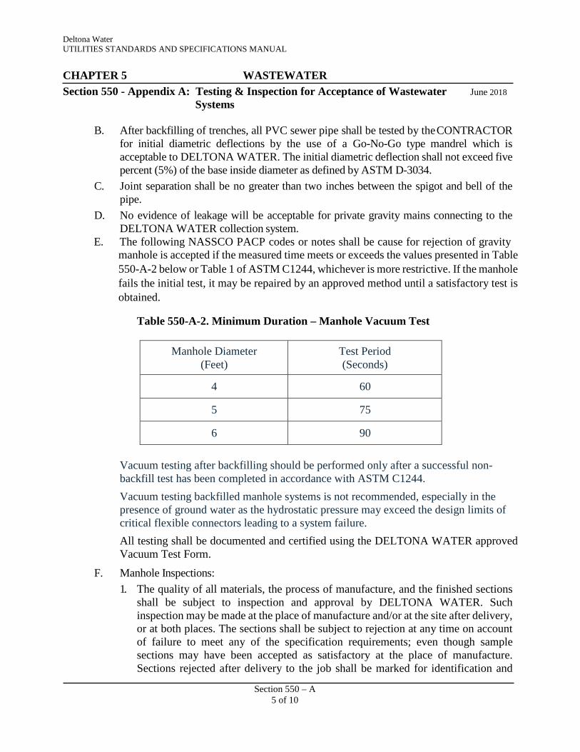
Deltona Water UTILITIES STANDARDS AND SPECIFICATIONS MANUAL CHAPTER 5 WASTEWATER Section 550 - Appendix A: Testing & Inspection for Acceptance of Wastewater June 2018
Systems
Section 550 – A 5 of 10
B. After backfilling of trenches, all PVC sewer pipe shall be tested by the CONTRACTOR for initial diametric deflections by the use of a Go-No-Go type mandrel which is acceptable to DELTONA WATER. The initial diametric deflection shall not exceed five percent (5%) of the base inside diameter as defined by ASTM D-3034.
C. Joint separation shall be no greater than two inches between the spigot and bell of the pipe.
D. No evidence of leakage will be acceptable for private gravity mains connecting to the DELTONA WATER collection system.
E. The following NASSCO PACP codes or notes shall be cause for rejection of gravity manhole is accepted if the measured time meets or exceeds the values presented in Table 550-A-2 below or Table 1 of ASTM C1244, whichever is more restrictive. If the manhole fails the initial test, it may be repaired by an approved method until a satisfactory test is obtained.
Table 550-A-2. Minimum Duration – Manhole Vacuum Test
Manhole Diameter (Feet)
Test Period (Seconds)
4 60
5 75
6 90
Vacuum testing after backfilling should be performed only after a successful non- backfill test has been completed in accordance with ASTM C1244. Vacuum testing backfilled manhole systems is not recommended, especially in the presence of ground water as the hydrostatic pressure may exceed the design limits of critical flexible connectors leading to a system failure. All testing shall be documented and certified using the DELTONA WATER approved Vacuum Test Form.
F. Manhole Inspections: 1. The quality of all materials, the process of manufacture, and the finished sections
shall be subject to inspection and approval by DELTONA WATER. Such inspection may be made at the place of manufacture and/or at the site after delivery, or at both places. The sections shall be subject to rejection at any time on account of failure to meet any of the specification requirements; even though sample sections may have been accepted as satisfactory at the place of manufacture. Sections rejected after delivery to the job shall be marked for identification and
Deltona Water UTILITIES STANDARDS AND SPECIFICATIONS MANUAL CHAPTER 5 WASTEWATER Section 550 - Appendix A: Testing & Inspection for Acceptance of Wastewater June 2018
Systems
Section 550 – A 6 of 10
shall be immediately removed from the job. All sections, which have been damaged, will be rejected. If already installed, rejected section shall be removed and replaced entirely at the CONTRACTOR’s expense.
2. At the time of inspection, the sections will be carefully examined for compliance with the specified ASTM designation, and with the approved manufacturer's drawings. All sections shall be inspected for general appearance, dimension, “scratch-strength” blisters, cracks, roughness, soundness, etc. The surface shall be dense and close-textured. Installed manholes shall be inspected for proper filling and coating of the lifting holes and proper installation of any liner, coating or shrink-wrap.
sewer systems 1. PACP coding of “Line” (L) shall be accompanied by a measurement of the line,
grade or angular deviation. Variance of established line and grade at any point along the length of the pipe shall not be greater than 1-1/2 inches, provided such variation does not result in a level or reverse sloping invert. An approved method shall be used to determine this deviation. A PACP coding of MWLS with a percentage of pipe greater than 18.75% on 8-inch sewer, 15% on 10-inch sewer etc. will be corrected by excavation and repair.
2. PACP coding of “Infiltration” (I) for pipe joints shall be replaced or the pipe joint shall be reseated at the joint. Grouting shall not be considered a method of repair and will not be accepted. Replace the leaking gravity main segment if there is visible infiltration at any point other than the pipe joint.
3. Any PACP coding in the category of “Structural Family”. 4. PVC pipe having ID tears will be rejected. 5. PACP condition grading of “OB” (obstruction) in pipe shall be rejected, the
obstruction shall be removed and the line cleaned and re-televised.
3.03 ACCEPTANCE OF GRAVITY MAINS A. Successful passage of both the leakage test and CCTV inspection is required before
acceptance by DELTONA WATER. B. Prior to repair or replacement of failed sewer pipe, the method of repair or replacement
shall be submitted to DELTONA WATER for review and consideration for approval. Pressure grouting of pipe or manholes shall not be considered as an acceptable method of repair.

Deltona Water UTILITIES STANDARDS AND SPECIFICATIONS MANUAL CHAPTER 5 WASTEWATER Section 550 - Appendix A: Testing & Inspection for Acceptance of Wastewater June 2018
Systems
Section 550 – A 7 of 10
PART 4 – MANHOLE TESTING
4.01 TESTING AND INSPECTION OF MANHOLES A. Leakage Test:
There shall be no visible leakage through the walls or pipe connections.
B. Vacuum Test: All manholes shall be required to meet the requirements of the vacuum test as per the current ASTM C 1244 “Standard Test Method for Concrete Sewer Manholes by the Negative Air Pressure (Vacuum) Test” prior to acceptance.
ASTM C1244 states that a vacuum test is intended to be used as a preliminary test to enable the installer to demonstrate the condition of the concrete manhole prior to backfill.
ASTM C1244 requires that a vacuum of 10 inches Hg to be drawn on the manhole after all lift holes are plugged and pipes entering the manhole are temporarily plugged and securely braced. The time is measured for the vacuum to drop to 9 inches Hg.
PART 5 – TESTING OF WASTEWATER FORCE MAINS
A. Locating Wire System: All wastewater force mains shall be installed with a continuous green insulated copper locating wire. Locating wire shall be installed in accordance with the STANDARD DRAWINGS and pass a continuity check with an approved tracing system before acceptance by DELTONA WATER.
B. Inspection of Automatic Combination Air and Vacuum Release Valves: After completion of the pressure test the ARV shutoff valve shall be opened and DELTONA WATER shall test the ARV for proper connection and operation.
C. Inspection of Valves and Valve Boxes: Valves shall be opened wide, then tightly closed, and the various nut and bolts shall be tested for tightness. Any valve that does not operate correctly shall be replaced. Buried valves shall have an operating nut within two feet of finished grade. Valve boxes shall be properly marked and checked for installation in accordance with the STANDARD DRAWINGS. Operating nuts, extensions, and upper guides shall not interfere with valve operation. Before acceptance by DELTONA WATER valve boxes shall be adjusted to finished grade with the operating nut properly centered and shall have a “V” notched in the curb or street in the absence of a curb directly opposite the valve box.
D. Swabbing:

Deltona Water UTILITIES STANDARDS AND SPECIFICATIONS MANUAL CHAPTER 5 WASTEWATER Section 550 - Appendix A: Testing & Inspection for Acceptance of Wastewater June 2018
Systems
Section 550 – A 8 of 10
1. All mains shall be hydraulically cleaned with a polypropylene swabbing (also known as pigging) device to remove dirt, sand, and debris from main.
2. If swabbing access and egress points are not provided in the design drawings, it will be the responsibility of the CONTRACTOR to provide and remove temporary access and egress points for the cleaning, as required.
3. Passage of cleaning poly swabs through the system shall be constantly monitored, controlled, and all poly swabs entered into the system shall be individually marked and identified so that the exiting of the poly swabs from the system can be confirmed.
4. Cleaning of the system shall be done in conjunction with the initial filling of the system for its hydrostatic test.
5. The line to be cleaned shall only be connected to the existing distribution system at a single connection point.
6. The CONTRACTOR shall locate and open all new in-line valves beyond the point of connection on the pipeline to be cleaned during the swabbing operation.
7. At the receiver or exit point for the poly swab, the CONTRACTOR is responsible for creating a safe environment for collection of debris, water, and the swab. The CONTRACTOR shall provide for the protection of surrounding personnel and property and the safe retrieval of the swab.
8. Only DELTONA WATER personnel shall operate the supply valve from the existing distribution system. Cleaning and flushing shall be accomplished by propelling the swab down the pipeline to the exit point with potable water. Flushing shall continue until the water is completely clear and swab is retrieved.
i. Re-apply a series of individual swabs in varying diameters and/or densities as required, to attain proper cleanliness of pipeline.
ii. Swabbing speed shall range between two and five feet per second. 9. After the swabbing process, pressure testing and disinfection of the pipe shall be
completed in accordance with this MANUAL.
E. Hydrostatic Pressure Testing of Ductile Iron and PVC Pressure Pipe: 1. Hydrostatic tests shall consist of pressure and leakage tests for non-butt welded jointed
pipes. Air testing of pressure pipes will not be permitted under any circumstance. Testing shall be performed from in-line valve to in-line valve with a depressurized section behind each valve, whenever possible. Testing shall be performed from in-line valve to in-line valve with a depressurized section behind each valve, whenever possible.
2. The CONTRACTOR shall furnish all necessary testing material and equipment. DELTONA WATER will monitor and approve a satisfactory test.
3. All pipe sections to be pressure tested shall be subjected to a hydrostatic pressure of 150 psi. The duration of each pressure test shall be for a period of two hours. If
Deltona Water UTILITIES STANDARDS AND SPECIFICATIONS MANUAL CHAPTER 5 WASTEWATER Section 550 - Appendix A: Testing & Inspection for Acceptance of Wastewater June 2018
Systems
Section 550 – A 9 of 10
during the test, the integrity of the tested line is in question, DELTONA WATER may require a 6-hour pressure test. The basic provisions of AWWA C600 shall be applicable.
4. Procedure for Pressure Test: Each section of pipe to be tested, as determined by DELTONA WATER, shall be slowly filled with water and the specified test pressure shall be applied by means of a pump connected to the pipe in a satisfactory manner. Before applying the specified test pressure, all air shall be expelled from the pipe. To accomplish this, taps shall be made and appropriate valves installed to ensure bleeding of all air from the main. If defective pipes, fittings or valves are discovered during this pressure test, all such items shall be removed and replaced by the CONTRACTOR with sound material and the test shall be repeated until satisfactory results are obtained. Provisions of the current AWWA C600, where applicable, shall apply.
F. Hydrostatic Pressure Testing of HDPE and Fusible PVC Pressure Pipe: 1. After installation, the butt welded jointed pipe shall be tested in accordance with this
MANUAL with the following modifications:
a. Test Duration: The total test time including initial pressurization, initial expansion, and time at test pressure, shall not exceed five hours. If the test is not completed due to leakage, equipment failure, etc., the test section shall be depressurized and allowed to “relax” for a minimum of eight hours before it is brought back up to test pressure. The test procedure consists of initial expansion phase and leakage test phase.
b. Prior to Hydrostatic Pressure Testing Procedure: 1) Hydraulically clean the main to be tested with a polypropylene swab (pig) to
remove dirt, sand, and debris from the main prior to hydrostatic testing. 2) Insure that main to be tested is restrained against horizontal and vertical
movement. Exposing joints only is allowed. c. Hydrostatic Pressure Testing Procedure:
1) Fill main slowly with water to remove air. 2) Pressurize up to 1.5 times the Pressure Class of the pipe used at the lowest
point of the main being tested. 3) Maintain for 4 hours while adding water as needed in non-monitored
amounts as pipe will expand while until pressure. 4) Reduce pressure by 10 psi and monitor for 1 hour. 5) Main passes if there are no leaks within 5 percent of the remaining pressure
after reduction.

Deltona Water UTILITIES STANDARDS AND SPECIFICATIONS MANUAL CHAPTER 5 WASTEWATER Section 550 - Appendix A: Testing & Inspection for Acceptance of Wastewater June 2018
Systems
Section 550 – A 10 of 10
G. Hydrostatic Leakage Testing: a. Procedure for Leakage Test: After completion of the pressure test, a leakage test shall be conducted to determine the quantity of water lost by leakage under the specified test pressure. Applicable provisions of AWWA C600 shall apply.
i. Allowable leakage in gallons per 100 feet of pipeline shall not be greater than that determined by the following table:
Table 550-A-3. Allowance for Hydrostatic Leakage Test*
Test Duration (hours)
Pipe Diameter (inches)
2 4 6 8 12 16 20 24
Allowance/100 feet of Pipeline (gallons)
2 0.11 0.25 0.60 1.00 2.30 3.30 5.50 8.90
3 0.19 0.40 0.90 1.50 3.40 5.50 8.00 13.30
*Applies to test period and not to initial expansion phase
ii. Leakage is defined as the quantity of water to be supplied in the installed pipe or any valve section under test, which is necessary to maintain the specified leakage test pressure after the pipe has been filled with water and the air expelled. Should any test of pipe installed disclose leakage greater than that allowed, the CONTRACTOR shall locate and replace or repair the defective joints, pipe or valve until subsequent testing is within the specified leakage allowance.
H. All testing and the quantity of acceptable leakage shall be documented and certified using the DELTONA WATER approved Pressure Test Form.

Deltona Water UTILITIES STANDARDS AND SPECIFICATIONS MANUAL CHAPTER 5 WASTEWATER
Section 550 – Appendix B: Testing and Inspection for Acceptance of Wastewater June 2018 Lift Stations
Section 550 – B
1 of 5
PART 1 – GENERAL
1.01 SCOPE OF WORK
A. This Section covers the testing and inspection for acceptance of Wastewater Lift Stations.
B. Requests for testing and acceptance of Wastewater Lift Stations shall be executed in accordance with Section 318 entitled “Field Testing and Inspection Procedures”.
C. The final startup and final inspection shall demonstrate and ensure to DELTONA WATER that the complete lift station system is fully operational in accordance with this MANUAL.
PART 2 – PRODUCTS (NOT USED)
PART 3 – EXECUTION
3.01 PREPARATION FOR TESTING A. The CONTRACTOR shall install sufficient monitoring wells in the representative
areas of the gravity system, acceptable to DELTONA WATER, to determine the groundwater elevations. Monitoring wells shall be installed a minimum 24-hours prior to Section 3.02 testing.
3.02 TESTING AND INSPECTION OF WETWELLS
A. Leakage Test:
There shall be no visible leakage through the walls or pipe connections.
B. Wet Well Liner/Coating Testing:
All wet well surfaces with linings or coatings shall be tested with an acceptable electrical Holiday or flaw detector, if applicable, after installation and any imperfections discovered shall be repaired by a method approved by DELTONA WATER. The CONTRACTOR shall provide all necessary equipment and material for testing. Liners and coatings requiring spark testing will be spark tested in accordance with NACE Standard RP-02-74. Test voltage equals 1,250 multiplied by the square root of the coating thickness in mils (0.001 inch), or test voltage equals 250 multiplied by the square root of the coating material in microns (0.001 mm) this
Deltona Water UTILITIES STANDARDS AND SPECIFICATIONS MANUAL CHAPTER 5 WASTEWATER
Section 550 – Appendix B: Testing and Inspection for Acceptance of Wastewater June 2018 Lift Stations
Section 550 – B
2 of 5
formula’s results shall not exceed the dielectric strength of the material being tested.
3.03 FINAL LIFT STATION START-UP
A. The following shall occur prior to the Final Lift Station Start Up being conducted:
1. A successful Informal Lift Station Start Up of the lift station, its site, and improvements.
2. All wire checks completed.
3. Wastewater Collection System CCTV inspections has been successfully completed and reviewed by DELTONA WATER.
4. FDEP Water Clearance received by DELTONA WATER.
5. FDEP placard for fuel tank, if applicable, has been received and properly located on the tank.
6. A “Lift Station Start-Up Form”, as contained in this MANUAL, has been completed by the CONTRACTOR and received by DELTONA WATER.
7. Liner and coatings tests have been successfully completed and documentation received by DELTONA WATER.
8. All compaction tests, as required by Section 312 entitled “Excavations, Backfill, Compaction, and Grading Specifications”, have been successfully completed by the CONTRACTOR and reviewed by DELTONA WATER.
9. Two printed copies and one electronic copy in Acrobat “pdf” format of the Operation and Maintenance Manual for the lift station has been received by DELTONA WATER.
B. Prior to the formal acceptance of the lift station by the DELTONA WATER, a DELTONA WATER acceptable BOUNDARY SURVEY that includes all improvements within the lift station site and out to the centerline of the adjacent roadway shall be submitted to DELTONA WATER, in accordance with the Section entitled “Development Coordination”. The CONTRACTOR and DEVELOPER shall bear the entire expense of rectifying all WORK improperly installed due to the construction of improvements not totally within the site dedicated to DELTONA WATER. An electronic version and three copies of the certified BOUNDARY SURVEY shall be required.
Deltona Water UTILITIES STANDARDS AND SPECIFICATIONS MANUAL CHAPTER 5 WASTEWATER
Section 550 – Appendix B: Testing and Inspection for Acceptance of Wastewater June 2018 Lift Stations
Section 550 – B
3 of 5
C. The intent of the Formal Lift Station Start Up is for the CONTRACTOR to successfully demonstrate to DELTONA WATER that the WORK will function as a complete and operable system under normal as well as emergency operating conditions and the lift station is ready for acceptance. All testing and inspection activities shall demonstrate that all applicable items of this MANUAL and the approved construction documents have been met.
D. The CONTRACTOR shall furnish all labor, fuel, energy, lubrication, water and all other materials, equipment, tools, and instruments necessary for the Formal Lift Station Up along with all other testing and inspection activities. Prior to the Formal Lift Station Start Up, the CONTRACTOR shall conduct preliminary testing of all equipment and make all changes, adjustments, and replacements required. All materials used shall be in accordance with the appropriate “List of Approved Products”.
Listed below is a partial checklist of requirements to be met.
1. The CONTRACTOR shall coordinate the Informal and Formal Lift Station Start Up activities with DELTONA WATER, the manufacturer’s representatives, and subcontractors. A factory representative knowledgeable in the mechanical and electrical equipment furnished shall inspect and supervise the operation of their respective equipment during the Formal Lift Station Start Up. Upon satisfactory completion of the equipment testing and inspection, the factory representative(s) shall issue the required manufacturer's warranty certificates.
2. The CONTRACTOR shall initiate startup of each system in accordance with the lift station’s Operation and Maintenance Manual. The CONTRACTOR shall demonstrate that all of the components of each system are operating under their own controls as designated without overheating or overloading any parts and without objectionable vibration as determined by DELTONA WATER.
3. The CONTRACTOR shall observe the system operation and make adjustments as necessary to optimize the system performance. The CONTRACTOR shall coordinate with DELTONA WATER for any adjustments desired or operational problems requiring debugging.
4. All functions of the lift station mechanical and electrical equipment shall be tested and inspected for operation and workmanship by the CONTRACTOR. All equipment shall be properly installed and meet the design performance requirements.

Deltona Water UTILITIES STANDARDS AND SPECIFICATIONS MANUAL CHAPTER 5 WASTEWATER
Section 550 – Appendix B: Testing and Inspection for Acceptance of Wastewater June 2018 Lift Stations
Section 550 – B
4 of 5
5. The pumps shall be flow tested at the lift station startup to verify their performance meets the design requirements and the manufacturer’s pump curve.
6. A Lift Station Start-Up Report, as contained in this MANUAL, shall be completed by DELTONA WATER.
7. The DEVELOPER shall bear the entire expense of rectifying WORK installed outside the lift station property.
8. No generator shall be used to power any portion of the lift station during the Final Lift Station Start-Up.
E. Re-testing:
If the results of the Formal Lift Start Up do not meet the requirements of this MANUAL, the deficiencies shall be corrected and the Formal Lift Start Up shall be rescheduled in accordance with Section 318 entitled “Field Testing and Inspection Procedures”.
F. Fuel Tanks:
The CONTRACTOR, ENGINEER, and the DEVELOPER shall be fully responsible for complying with all COUNTY and FDEP (F.A.C. 62.762) storage tank installation protocols. The installation of any storage tank that is subject to the above standards shall be properly registered, insured, installed, and inspected accordingly. The CONTRACTOR shall provide a minimum 5 NORMAL WORKING DAYS advance notice of any storage tank installation to and receive written confirmation from the Public Works Director and the Purchasing Director. No fuel shall be placed within a fuel tank without the approval of DELTONA WATER.
1. Fuel tanks, with a capacity of less than 550 gallons, do not require registration by FDEP. However, “Less than 550” and “1993” stickers are to be obtained from DELTONA WATER and properly applied to the tanks prior to the Formal Lift Station Start Up.
2. Fuel tanks, with a capacity of 550 but less than 1,320 gallons, shall have a properly completed "Storage Tank Facility Registration Form" reviewed and approved by DELTONA WATER prior to it being submitted by the CONTRACTOR to the FDEP Fuel Tank Division, with all applicable fees. The
Deltona Water UTILITIES STANDARDS AND SPECIFICATIONS MANUAL CHAPTER 5 WASTEWATER
Section 550 – Appendix B: Testing and Inspection for Acceptance of Wastewater June 2018 Lift Stations
Section 550 – B
5 of 5
original FDEP Storage Tank Registration Placard shall be provided to DELTONA WATER prior to the Formal Lift Station Start Up. A “1993” sticker and a laminated copy of the FDEP Storage Tank Registration Placard shall be properly applied to the tanks prior to the Formal Lift Station Start Up.
3. Fuel tanks, with a capacity of 1,320 or more gallons, shall be required to have a “Spill Prevention, Control, and Countermeasure Plan (SPCC), that complies with Title 40, Code of Federal Regulations, Part 112, in addition to the requirements specified in the Section above.
G. Acceptance:
DELTONA WATER shall recommend the lift station for formal acceptance by the COUNTY once the lift station functions as a complete and operable system under normal as well as emergency operating conditions, has been certified by the ENGINEER that it complies with all applicable specifications of this MANUAL and the approved construction documents, and all observed deficiencies have been corrected to DELTONA WATER’s satisfaction.

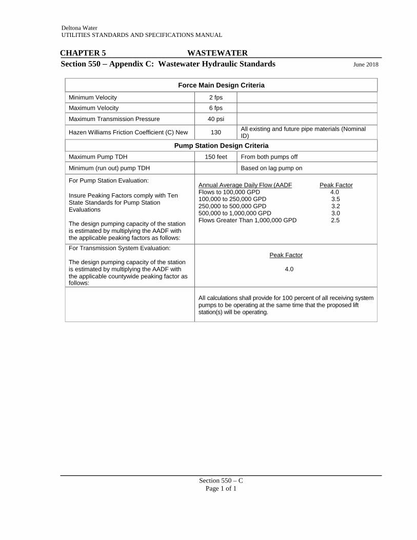
Deltona Water UTILITIES STANDARDS AND SPECIFICATIONS MANUAL
CHAPTER 5 WASTEWATER
Section 550 – Appendix C: Wastewater Hydraulic Standards June 2018
Force Main Design Criteria Minimum Velocity 2 fps
Maximum Velocity 6 fps
Maximum Transmission Pressure 40 psi
Hazen Williams Friction Coefficient (C) New 130 All existing and future pipe materials (Nominal ID)
Pump Station Design Criteria Maximum Pump TDH 150 feet From both pumps off
Minimum (run out) pump TDH Based on lag pump on
For Pump Station Evaluation:
Insure Peaking Factors comply with Ten State Standards for Pump Station Evaluations
The design pumping capacity of the station is estimated by multiplying the AADF with the applicable peaking factors as follows:
Annual Average Daily Flow (AADF Peak Factor Flows to 100,000 GPD 4.0 100,000 to 250,000 GPD 3.5 250,000 to 500,000 GPD 3.2 500,000 to 1,000,000 GPD 3.0 Flows Greater Than 1,000,000 GPD 2.5
For Transmission System Evaluation:
The design pumping capacity of the station is estimated by multiplying the AADF with the applicable countywide peaking factor as follows:
Peak Factor
4.0
All calculations shall provide for 100 percent of all receiving system pumps to be operating at the same time that the proposed lift station(s) will be operating.
Section 550 – C Page 1 of 1


Deltona Water UTILITIES STANDARDS AND SPECIFICATIONS MANUAL
CHAPTER 5 WASTEWATER
Section 550 – Appendix D: Wastewater Force Main Pressure Test Form June 2018 (PVC and Ductile Iron Pipe)
Project: DW Project No.:
Procedures for conducting this test shall be in strict conformance with AWWA standard C600, latest revision. Maximum allowable leakage in gallons per 100 feet of pipeline shall not be greater than that determined by the following table:
Allowance for Hydrostatic Leakage Test*
Test Duration (hours)
Pipe Diameter (inches)
2 4 6 8 12 16 20 24
Allowance/100 feet of Pipeline (gallons)
2 0.11 0.25 0.60 1.00 2.30 3.30 5.50 8.90
3 0.19 0.40 0.90 1.50 3.40 5.50 8.00 13.30
*Applies to test period and not to initial expansion phase
TESTING PARAMETERS & SYSTEM INFORMATION Test Pressure (minimally 150 psi): psi Beginning Test Pressure: psi Ending Test Pressure: psi Test Duration (minimally 2 hours): Hours: Date of Test: Time at Start of Test: Time at End of Test: Test Segment Location:
Pipe Type Diameter, inches Length, feet Number of Joints Max. Leakage for 2
Hour Test, gallons Total Maximum Allowable Leakage, gallons: Total Actual Leakage, gallons:
CONTRACTOR & INSPECTOR PERSONNEL INFORMATION Contractor Inspector Signature: Printed Name: Company Name: Phone Number: Date:
Section 550 – D
Page 1 of 1


Section 550 – E
Page 1 of 1
Deltona Water UTILITIES STANDARDS AND SPECIFICATIONS MANUAL
CHAPTER 5 WASTEWATER
Section 550 – Appendix E: Wastewater Force Main Pressure Test Form June 2018 (HDPE Pipe)
Project: DW Project No.:
Procedures for conducting this test shall be in accordance with ASTM F 2164 and AWWA Standard C600, latest revision, where applicable. Pneumatic Testing is strictly prohibited.
Prior to Hydrostatic Pressure Testing Procedure:
1) Flush main with a minimum velocity of 3 fps to clear foreign materials. 2) Insure that main to be tested is restrained against horizontal and vertical movement.
Exposing joints only is allowed.
Hydrostatic Pressure Testing Procedure: 1) Fill main slowly with water to remove air. 2) Pressurize up to 1.5 times the Pressure Class of the pipe used at the lowest point of the
main being tested. 3) Maintain for 4 hours while adding water as needed in non-monitored amounts as pipe
will expand while until pressure. 4) Reduce pressure by 10 psi and monitor for 1 hour. 5) Main passes if there are no leaks within 5 percent of the remaining pressure after
reduction.
TESTING PARAMETERS & SYSTEM INFORMATION Calculated Test Pressure: psi Beginning Test Pressure:
psi Ending Test Pressure: psi
Test Duration (minimally 5 hours): Hours: Date of Test: Time at Start of Test: Time at End of Test:
Diameter, inches Length, feet Pressure Class, psi Test Segment Location
CONTRACTOR & INSPECTOR PERSONNEL INFORMATION Contractor Inspector Signature: Printed Name: Company Name: Phone Number:


Section 550 – F Page 1 of 1
Deltona Water UTILITIES STANDARDS AND SPECIFICATIONS MANUAL
CHAPTER 5 WASTEWATER
Section 550 – Appendix F: Wastewater System CCTV and Mandrel Inspection June 2018 Report
Project: DW Project No.:
Test Date: Street Name: Pipe Size: Pipe Type & Pipe
Specification:
Start MH #: Start MH Depth: End MH #: End MH Depth: 5% Mandrel Pulled With or Against Flow Path? Camera Pulled With or Against Flow Path?
Tape Counter
Actual Footage Clock Reference Comment/Description
CONTRACTOR & INSPECTOR PERSONNEL INFORMATION Contractor Inspector Signature: Printed Name: Company Name:
Phone Number: Date:

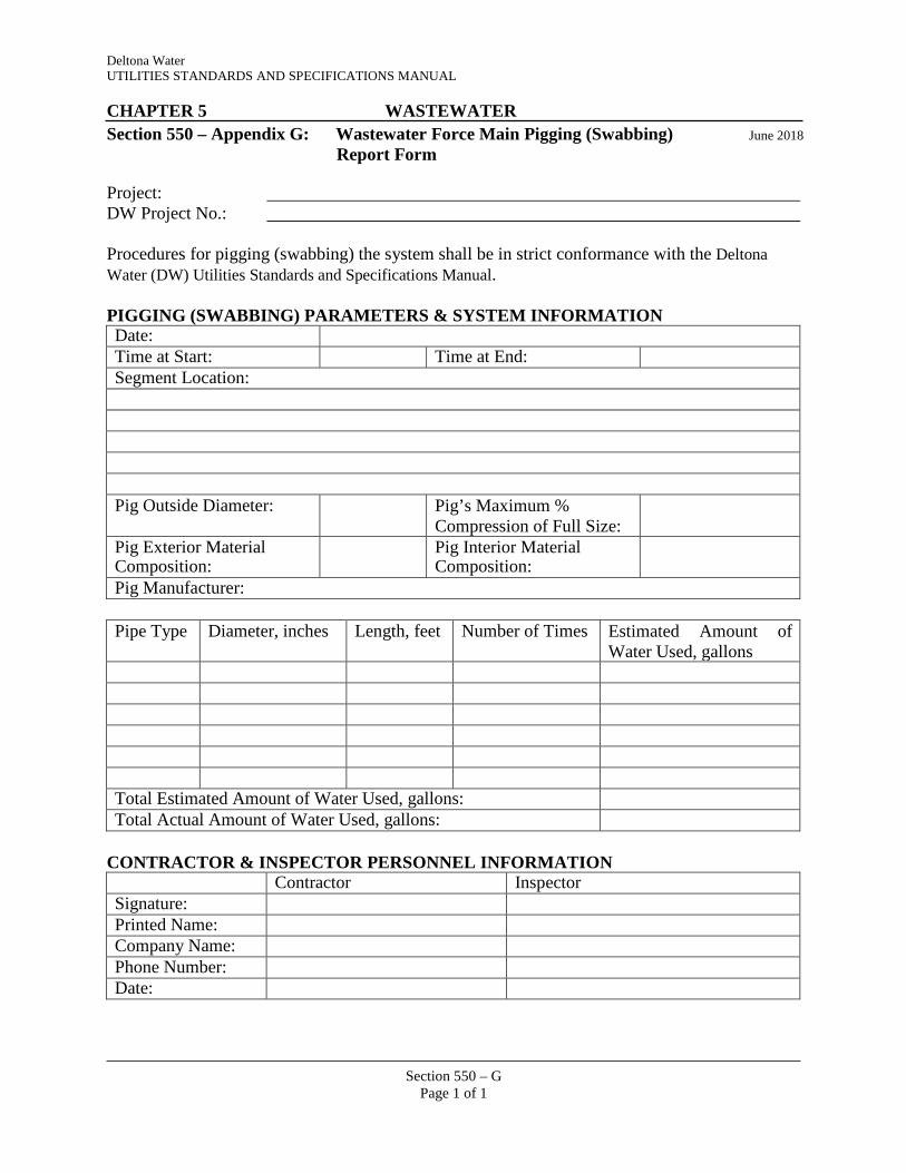
Section 550 – G
Page 1 of 1
Deltona Water UTILITIES STANDARDS AND SPECIFICATIONS MANUAL
CHAPTER 5 WASTEWATER
Section 550 – Appendix G: Wastewater Force Main Pigging (Swabbing) June 2018 Report Form
Project: DW Project No.:
Procedures for pigging (swabbing) the system shall be in strict conformance with the Deltona Water (DW) Utilities Standards and Specifications Manual.
PIGGING (SWABBING) PARAMETERS & SYSTEM INFORMATION Date: Time at Start: Time at End: Segment Location:
Pig Outside Diameter: Pig’s Maximum %
Compression of Full Size:
Pig Exterior Material Composition:
Pig Interior Material Composition:
Pig Manufacturer:
Pipe Type Diameter, inches Length, feet Number of Times Estimated Amount of Water Used, gallons
Total Estimated Amount of Water Used, gallons: Total Actual Amount of Water Used, gallons:
CONTRACTOR & INSPECTOR PERSONNEL INFORMATION Contractor Inspector Signature: Printed Name: Company Name: Phone Number: Date:

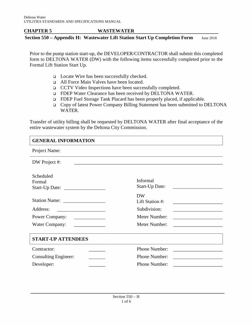
Deltona Water UTILITIES STANDARDS AND SPECIFICATIONS MANUAL CHAPTER 5 WASTEWATER
Section 550 – Appendix H: Wastewater Lift Station Start Up Completion Form June 2018
Section 550 – H 1 of 6
Prior to the pump station start-up, the DEVELOPER/CONTRACTOR shall submit this completed form to DELTONA WATER (DW) with the following items successfully completed prior to the Formal Lift Station Start Up.
Locate Wire has been successfully checked. All Force Main Valves have been located. CCTV Video Inspections have been successfully completed. FDEP Water Clearance has been received by DELTONA WATER. FDEP Fuel Storage Tank Placard has been properly placed, if applicable. Copy of latest Power Company Billing Statement has been submitted to DELTONA
WATER.
Transfer of utility billing shall be requested by DELTONA WATER after final acceptance of the entire wastewater system by the Deltona City Commission.
GENERAL INFORMATION
Project Name:
DW Project #:
Scheduled Formal Start-Up Date:
Informal Start-Up Date:
Station Name:
DW Lift Station #:
Address: Subdivision: Power Company: Meter Number: Water Company: Meter Number:
START-UP ATTENDEES
Contractor: Phone Number: Consulting Engineer: Phone Number: Developer: Phone Number:

Deltona Water UTILITIES STANDARDS AND SPECIFICATIONS MANUAL CHAPTER 5 WASTEWATER
Section 550 – Appendix H: Wastewater Lift Station Start Up Completion Form June 2018
Section 550 – H 2 of 6
Utilities Inspector: Phone Number:
CONTROL PANEL
Control Panel Rep: Phone Number: Control Panel Name: Serial Number:
SCADA PANEL
SCADA Panel Rep: Phone Number: SCADA Panel Name: Serial Number:
ELECTRICAL EQUIPMENT
Main Service Voltage: Amperage: Main Breaker Name: Amperage: Pump Breaker Name: Amperage: Control Breaker Name: Amperage: Main Disconnect: Amperage: Is Disconnect Lockable? YES NO
TVSS Type: Transformer: Primary: Secondary: KVA: Alternator Name: Phase Monitor Name: Type: Starter Name: Size: Heater Size: Voltage: Phase: Amps: Horse Power:
Pressure Transducer Manufacturer:
Main Service SCA (Available Short Circuit Amperage):
Main Breaker AIC (Short Circuit Amps Capacity):
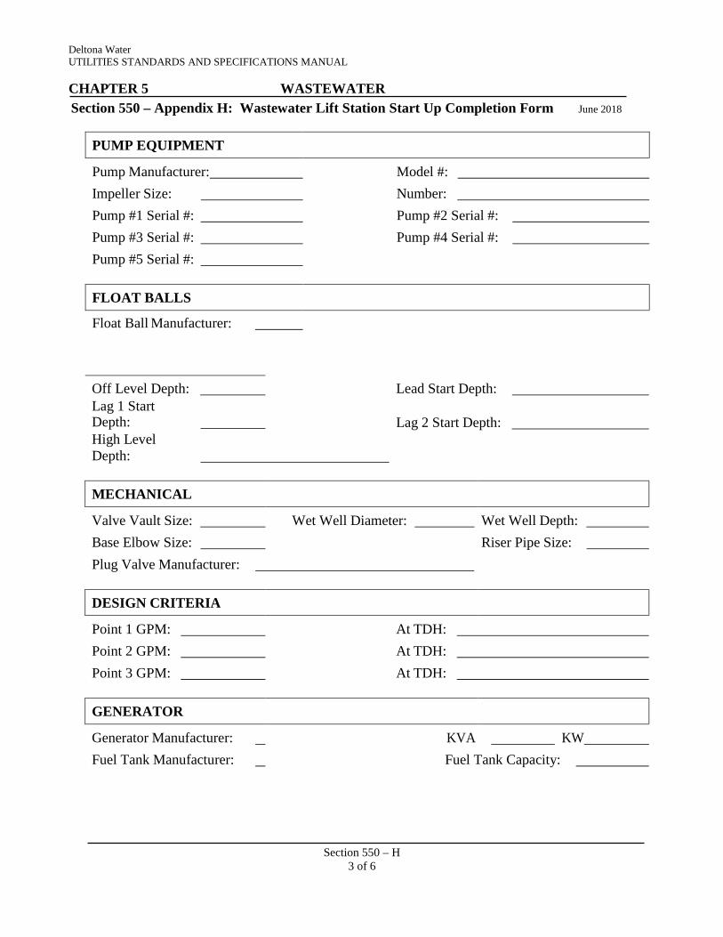
Deltona Water UTILITIES STANDARDS AND SPECIFICATIONS MANUAL CHAPTER 5 WASTEWATER
Section 550 – Appendix H: Wastewater Lift Station Start Up Completion Form June 2018
Section 550 – H 3 of 6
PUMP EQUIPMENT
Pump Manufacturer: Model #: Impeller Size: Number: Pump #1 Serial #: Pump #2 Serial #: Pump #3 Serial #: Pump #4 Serial #: Pump #5 Serial #:
FLOAT BALLS
Float Ball Manufacturer:
Off Level Depth: Lead Start Depth: Lag 1 Start Depth:
Lag 2 Start Depth:
High Level Depth:
MECHANICAL
Valve Vault Size: Wet Well Diameter: Wet Well Depth: Base Elbow Size: Riser Pipe Size: Plug Valve Manufacturer:
DESIGN CRITERIA
Point 1 GPM: At TDH: Point 2 GPM: At TDH: Point 3 GPM: At TDH:
GENERATOR
Generator Manufacturer: KVA KW Fuel Tank Manufacturer: Fuel Tank Capacity:

Deltona Water UTILITIES STANDARDS AND SPECIFICATIONS MANUAL CHAPTER 5 WASTEWATER
Section 550 – Appendix H: Wastewater Lift Station Start Up Completion Form June 2018
Section 550 – H 4 of 6
Generator Plug Manufacturer:
Transfer Switch Manufacturer: Generator Serial Number: Generator Model Number: Day Tank Capacity: Year of Manufacture:
Engine Manufacture: Engine Model Number: Engine Serial Number: Tire Size, if Portable:
CROSS CONNECTION CONTROL
Cross Connection Control Assembly Manufacturer:
Model #:
FLOW METER
Flow Meter Manufacturer:
Flow Meter Model #:
ODOR CONTROL SYSTEM
Manufacturer: Additive Type:
For DELTONA WATER Use Only
PUMPING CAPACITY
PS# 1 PS# 2 PS# 3 PS# 4 PS# 5 GPM at Startup:

Deltona Water UTILITIES STANDARDS AND SPECIFICATIONS MANUAL CHAPTER 5 WASTEWATER
Section 550 – Appendix H: Wastewater Lift Station Start Up Completion Form June 2018
Section 550 – H 5 of 6
TDH at Startup: PSI at Startup:
ELECTRICAL Phase A: Phase B: Phase C: # 1 Pump Amps at Startup # 2 Pump Amps at Startup # 3 Pump Amps at Startup # 4 Pump Amps at Startup # 5 Pump Amps at Startup Pump Megs Pump # 1: Pump # 2: Pump # 3:
Pump # 4: Pump # 5: Incoming Service Voltage A to B: A to C: B to C:
A to GND: B to GND: C to GND:
MECHANICAL
Plug Valve Size: Plug Valve Length Check Valve Manufacturer: Check Valve Size: Type: Check Valve Lay Length: Oil Filled Gauges: Manufacturer: By-Pass Size: Female Cam-Lock: Pipe Size(s) Entering Wet-Well:

Deltona Water UTILITIES STANDARDS AND SPECIFICATIONS MANUAL CHAPTER 5 WASTEWATER
Section 550 – Appendix H: Wastewater Lift Station Start Up Completion Form June 2018
Section 550 – H 6 of 6
Station Pumps To: O & M Manual Digital Copy Provided? YES NO Property Survey Report Provided? YES NO FDEP Fuel Tank Placard, if applicable YES NO Certification of ARC Testing for Liner Provided? YES NO Comments:
List Deficiencies/Discrepancies:

WASTEWATER Wastewater Schedule of Values Form
CHAPTER 5 Section 550 – Appendix I:
Deltona Water UTILITIES STANDARDS AND SPECIFICATIONS MANUAL
June 2018
Section 550 – I 1 of 4
Date:
Contractor:
Project:
DW Project No.:
Item No. Item Description Qty. Unit Unit Cost ($)
Extended Cost ($)
1 Single Service, Long 2 Single Service, Short 3 Double Service, Long 4 Double Service, Short 5 8” PVC, SDR-26, 0’-6’ deep 6 8” PVC, SDR-26, 6’-8’ deep 7 8” PVC, SDR-26, 8’-10’ deep 8 8” PVC, SDR-26, 10’-12’ deep 9 8” PVC, SDR-26, 12’-14’ deep 10 8” PVC, SDR-26, 14’-16’ deep 11 10” PVC, SDR-26, 0’-6’ deep 12 10” PVC, SDR-26, 6’-8’ deep 13 10” PVC, SDR-26, 8’-10’ deep 14 10” PVC, SDR-26, 10’-12’ deep 15 10” PVC, SDR-26, 12’-14’ deep 16 10” PVC, SDR-26, 14’-16’ deep 17 12” PVC, SDR-26, 0’-6’ deep 18 12” PVC, SDR-26, 6’-8’ deep 19 12” PVC, SDR-26, 8’-10’ deep 20 12” PVC, SDR-26, 10’-12’ deep 21 12” PVC, SDR-26, 12’-14’ deep 22 12” PVC, SDR-26, 14’-16’ deep 23 16” PVC, SDR-26, 0’-6’ deep 24 16” PVC, SDR-26, 6’-8’ deep 25 16” PVC, SDR-26, 8’-10’ deep 26 16” PVC, SDR-26, 10’-12’ deep 27 16” PVC, SDR-26, 12’-14’ deep 28 16” PVC, SDR-26, 14’-16’ deep 29 Standard Precast Manhole with
Ring and Cover, 0’-6’ deep

WASTEWATER Wastewater Schedule of Values Form
CHAPTER 5 Section 550 – Appendix I:
Deltona Water UTILITIES STANDARDS AND SPECIFICATIONS MANUAL
June 2018
Section 550 – I 2 of 4
30 Standard Precast Manhole with Ring and Cover, 6’-8’ deep
31 Standard Precast Manhole with Ring and Cover, 8’-10’ deep
32 Standard Precast Manhole with Ring and Cover, 10’-12’ deep
33 Standard Precast Manhole with Ring and Cover, 12’-14’ deep
34 Standard Precast Manhole with Ring and Cover, 14’-16’ deep
35 Pump Station, Duplex Complete 36 Pump Station, Triplex Complete 37 Standby Generator Set 38 Odor Control System 39 40 41 4” PVC, AWWA C900, DR 18,
Green
42 4’ DIP, Pressure Class 350, Epoxy-Lined, Bituminous Coated
43 4” Gate Valve Assembly, Complete
44 4” 11 ¼ Degree Bend, DI, C153, Epoxy-Lined, Bituminous Coated
45 4” 22 ½ Degree Bend, DI, C153, Epoxy-Lined, Bituminous Coated
46 4” 45 Degree Bend, DI, C153, Epoxy-Lined, Bituminous Coated
47 4” 90 Degree Bend, DI, C153, Epoxy-Lined, Bituminous Coated
48 4” Tee, DI, C153, Epoxy-Lined, Bituminous Coated
49 4” Cross, DI, C153, Epoxy-Lined, Bituminous Coated
50 51 4” HDPE 52 53 6” PVC, AWWA C900, DR 18,
Green
54 6” DIP, Pressure Class 350, Epoxy-Lined, Bituminous Coated
55 6” Gate Valve Assembly, Complete
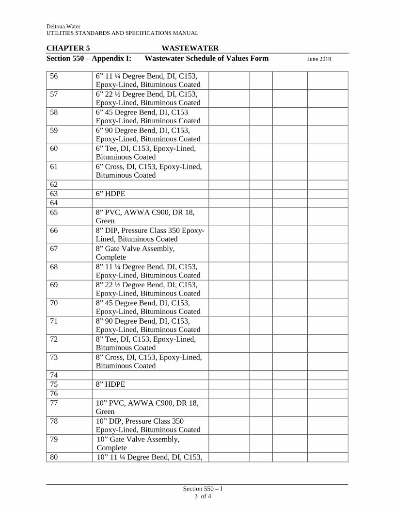
WASTEWATER Wastewater Schedule of Values Form
CHAPTER 5 Section 550 – Appendix I:
Deltona Water UTILITIES STANDARDS AND SPECIFICATIONS MANUAL
June 2018
Section 550 – I 3 of 4
56 6” 11 ¼ Degree Bend, DI, C153, Epoxy-Lined, Bituminous Coated
57 6” 22 ½ Degree Bend, DI, C153, Epoxy-Lined, Bituminous Coated
58 6” 45 Degree Bend, DI, C153 Epoxy-Lined, Bituminous Coated
59 6” 90 Degree Bend, DI, C153, Epoxy-Lined, Bituminous Coated
60 6” Tee, DI, C153, Epoxy-Lined, Bituminous Coated
61 6” Cross, DI, C153, Epoxy-Lined, Bituminous Coated
62 63 6” HDPE 64 65 8” PVC, AWWA C900, DR 18,
Green
66 8” DIP, Pressure Class 350 Epoxy- Lined, Bituminous Coated
67 8” Gate Valve Assembly, Complete
68 8” 11 ¼ Degree Bend, DI, C153, Epoxy-Lined, Bituminous Coated
69 8” 22 ½ Degree Bend, DI, C153, Epoxy-Lined, Bituminous Coated
70 8” 45 Degree Bend, DI, C153, Epoxy-Lined, Bituminous Coated
71 8” 90 Degree Bend, DI, C153, Epoxy-Lined, Bituminous Coated
72 8” Tee, DI, C153, Epoxy-Lined, Bituminous Coated
73 8” Cross, DI, C153, Epoxy-Lined, Bituminous Coated
74 75 8” HDPE 76 77 10” PVC, AWWA C900, DR 18,
Green
78 10” DIP, Pressure Class 350 Epoxy-Lined, Bituminous Coated
79 10” Gate Valve Assembly, Complete
80 10” 11 ¼ Degree Bend, DI, C153,

WASTEWATER Wastewater Schedule of Values Form
CHAPTER 5 Section 550 – Appendix I:
Deltona Water UTILITIES STANDARDS AND SPECIFICATIONS MANUAL
June 2018
Section 550 – I 4 of 4
Epoxy-Lined, Bituminous Coated 81 10” 22 ½ Degree Bend, DI, C153,
Epoxy-Lined, Bituminous Coated
82 10” 45 Degree Bend, DI, C153, Epoxy-Lined, Bituminous Coated
83 10” 90 Degree Bend, DI, C153, Epoxy-Lined, Bituminous Coated
84 10” Tee, DI, C153, Epoxy-Lined, Bituminous Coated
85 10” Cross, DI, C153, Epoxy- Lined, Bituminous Coated
86 87 10” HDPE 88 89 12” PVC, AWWA C900, DR 18,
Green
90 12” DIP, Pressure Class 350 Epoxy-Lined, Bituminous Coated
91 12” Gate Valve Assembly, Complete
92 12” 11 ¼ Degree Bend, DI, C153, Epoxy-Lined, Bituminous Coated
93 12” 22 ½ Degree Bend, DI, C153, Epoxy-Lined, Bituminous Coated
94 12” 45 Degree Bend, DI, C153, Epoxy-Lined, Bituminous Coated
95 12” 90 Degree Bend, DI, C153, Epoxy-Lined, Bituminous Coated
96 12” Tee, DI, C153, Epoxy-Lined, Bituminous Coated
97 12” Cross, DI, C153, Epoxy- Lined, Bituminous Coated
98 99 12” HDPE
Total Constructed Value:
Reviewer: Date:
Comments
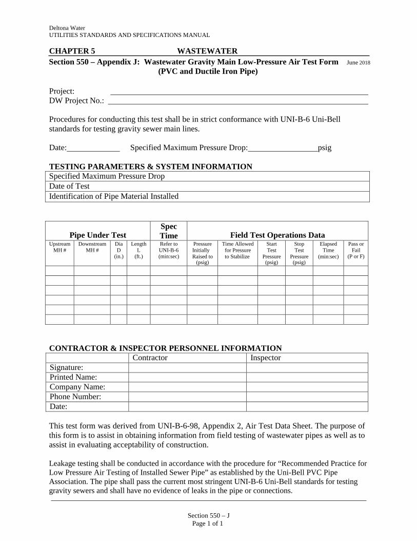
Section 550 – J
Page 1 of 1
Deltona Water UTILITIES STANDARDS AND SPECIFICATIONS MANUAL
CHAPTER 5 WASTEWATER
Section 550 – Appendix J: Wastewater Gravity Main Low-Pressure Air Test Form June 2018
(PVC and Ductile Iron Pipe)
Project: DW Project No.:
Procedures for conducting this test shall be in strict conformance with UNI-B-6 Uni-Bell standards for testing gravity sewer main lines.
Date: Specified Maximum Pressure Drop: psig
TESTING PARAMETERS & SYSTEM INFORMATION Specified Maximum Pressure Drop Date of Test Identification of Pipe Material Installed
Pipe Under Test Spec Time
Field Test Operations Data
Upstream MH #
Downstream MH #
Dia D
(in.)
Length L
(ft.)
Refer to UNI-B-6 (min:sec)
Pressure Initially Raised to
(psig)
Time Allowed for Pressure to Stabilize
Start Test
Pressure (psig)
Stop Test
Pressure (psig)
Elapsed Time
(min:sec)
Pass or Fail
(P or F)
CONTRACTOR & INSPECTOR PERSONNEL INFORMATION Contractor Inspector Signature: Printed Name: Company Name: Phone Number: Date:
This test form was derived from UNI-B-6-98, Appendix 2, Air Test Data Sheet. The purpose of this form is to assist in obtaining information from field testing of wastewater pipes as well as to assist in evaluating acceptability of construction.
Leakage testing shall be conducted in accordance with the procedure for “Recommended Practice for Low Pressure Air Testing of Installed Sewer Pipe” as established by the Uni-Bell PVC Pipe Association. The pipe shall pass the current most stringent UNI-B-6 Uni-Bell standards for testing gravity sewers and shall have no evidence of leaks in the pipe or connections.