Embed Size (px)
Citation preview

Prepared by
January 2010
in partnership with RS&H, PEQ, & PEDS
Chapter 6Design Guidelines

6-1 T:\08\8183-08 Cobb County Bike_Ped Improvement Plan\task 4\FINALfeb10\Ch 6 Doc.doc
Table of Contents CHAPTER 6: DESIGN GUIDELINES 6.1 Introduction .................................................................................................................................. 6-3 6.2 In-Street Bikeways ....................................................................................................................... 6-3
6.2.1 ROADWAY CROSS SECTION .................................................................................................... 6-3 6.2.2 INTERSECTION TREATMENTS ................................................................................................... 6-8 6.2.3 TRAFFIC SIGNALS ................................................................................................................. 6-21 6.2.4 OBSTRUCTION MARKINGS ..................................................................................................... 6-28
6.3 Shared Use Path Design ........................................................................................................... 6-28
6.3.1 DESIGN SPEED ..................................................................................................................... 6-28 6.3.2 STOPPING SIGHT DISTANCE .................................................................................................. 6-31 6.3.3 PATH WIDTH ........................................................................................................................ 6-31 6.3.4 CLEARANCES ....................................................................................................................... 6-34 6.3.5 HORIZONTAL ALIGNMENT ...................................................................................................... 6-36 6.3.6 VERTICAL ALIGNMENT ........................................................................................................... 6-38 6.3.7 INTERSECTIONS OF SHARED USE PATHS AND ROADWAYS ...................................................... 6-41
6.4 Bike Routes ................................................................................................................................ 6-54
6.4.1 GENERAL ROUTES ................................................................................................................ 6-54 6.4.2 NUMBER ROUTES ................................................................................................................. 6-55 6.4.3 ADDITIONAL WAYFINDING ...................................................................................................... 6-55
6.5 Other Design Considerations ................................................................................................... 6-56
6.5.1 DRAINAGE INLETS AND UTILITY COVERS ................................................................................ 6-56 6.5.2 RAILROAD CROSSINGS ......................................................................................................... 6-56 6.5.3 ON-STREET PARKING ........................................................................................................... 6-57 6.5.4 PAVEMENT SURFACE QUALITY .............................................................................................. 6-57 6.5.5 BICYCLE PARKING FACILITIES ................................................................................................ 6-57 6.5.6 BICYCLE AMENITIES .............................................................................................................. 6-58
6.6 Pedestrian Facilities .................................................................................................................. 6-58
6.6.1 SIDEWALK DESIGN ................................................................................................................ 6-58 6.6.2 PEDESTRIAN ROADWAY CROSSING DESIGN ........................................................................... 6-61
Appendix 6.A Rapid Rectangular Flashing Beacon ..................................................................... 6-67 Appendix 6.B Pedestrian Hybrid Signals ...................................................................................... 6-75 Appendix 6.C Pedestrian Signal Warrants .................................................................................... 6-81

6-2 T:\08\8183-08 Cobb County Bike_Ped Improvement Plan\task 4\FINALfeb10\Ch 6 Doc.doc

6-3 T:\08\8183-08 Cobb County Bike_Ped Improvement Plan\task 4\FINALfeb10\Ch 6 Doc.doc
Chapter 6:
Design Guidelines
6.1 INTRODUCTION This document provides guidelines and criteria for the design and operation of bicycle facilities. This document is a guidance document and does not create standards. While not intended to create standards, this guidance document does cite national criteria or practices that may be considered standards. Design standards reviewed during this document’s development include:
Cobb County Standard Details, Cobb County DOT
Cobb County Development Standards, Cobb County DOT
Georgia DOT Bike/Ped Design Policy
2009 Manual on Uniform Traffic Control Devices, FHWA
A Policy on the Geometric Design of Streets and Highways, AASHTO
Guide for the Development of Bicycle Facilities, AASHTO
Guide for the Planning, Design, and Operations of Pedestrian Facilities, AASHTO
Additional primary materials serving as reference for this document include:
Characteristics of Emerging Road and Trail Users and Their Safety, FHWA
Americans with Disabilities Act Architectural Guidelines, U.S. Access Board
6.2 IN-STREET BIKEWAYS 6.2.1 ROADWAY CROSS SECTION The Cobb County Bicycle and Pedestrian Master Plan includes desirable minimum level accommodations for bicyclists. Achieving this minimum level of accommodation needed on any given roadway may not necessarily require the provision of bicycle lanes or paved shoulders. Several design considerations, including facilities, pavement markings and signage are described below. Shared Roadways Bicyclists will, to varying extents, ride on nearly all of the roadways of Cobb County. Generally, roadways do not need any special geometric improvements to accommodate cyclists. However some roadway design components should be given consideration with respect to cyclists. Examples of these include bicycle safe drainage grates and expansion joints on bridges.
6-4 T:\08\8183-08 Cobb County Bike_Ped Improvement Plan\task 4\FINALfeb10\Ch 6 Doc.doc
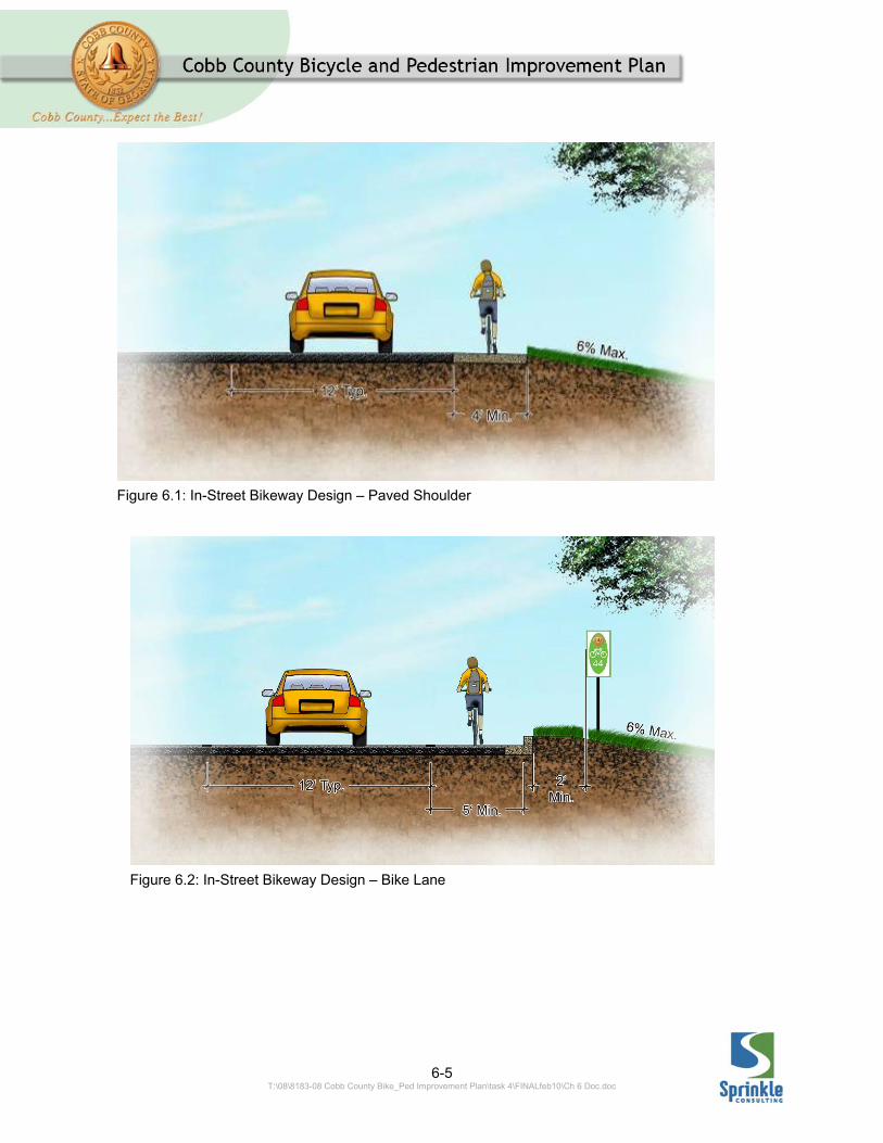
Wide curb lanes are a special example of a shared roadway facility. Fourteen feet is the recommended minimum width for a wide curb lane. (Note: While the AASHTO Bike Guide currently defines a Shared Roadway as “A roadway which is open to bicycle and motor vehicle travel.”1 The Manual on Uniform Traffic Control Devices (MUTCD) defines Shared Roadway as “a roadway that is officially designated as a bicycle route, but which is open to motor vehicle travel and upon which no bicycle lane is designated.”2 In this document, shared roadways will be considered as per the AASHTO definition.) Paved Shoulders Adding paved shoulders to an existing roadway without curb and gutter, or restriping a roadway to obtain a paved shoulder outside the travel lane can be an effective and relatively inexpensive way to improve a roadway for bicyclists. To accommodate cyclists, paved shoulders should be at least 4 feet wide and paved. See Figure 6.1. Bike Lanes A Bicycle Lane or Bike Lane, is a portion of a roadway that has been designated for preferential or exclusive
1 Guide for the Development of Bicycle Facilities, American Association of State Highway and Transportation Officials (AASHTO), Washington, DC, 1999, pg. 3. 2 MUTCD, FHWA, Washington, DC, 2009, P 20.
use by bicyclists by pavement markings and, if used, signs. They have very specific design, signing and striping criteria described in the AASHTO Bike Guide and the Manual on Uniform Traffic Control Devices. The following information on bike lanes is adapted from those documents unless otherwise stated. Width In sections with curb and gutter, bike lanes should be at least 5-feet wide measured from the face of curb. This 5-foot width assumes a minimum of a 3-foot wide rideable surface; the gutter pan is not included as part of the rideable surface. On sections of roadway without curb and gutter, a minimum width of 4-feet should be provided for a bike lane. Where a bike lane is striped next to striped on-street parking a minimum bike lane width of 5 feet is recommended. Where the parking lane is not separately striped, 11 feet clear from the bike lane stripe and the face of curb is recommended. See Figure 6.2. Additional width (for a total of 6 or even 8 feet) is desirable for roadways where substantial truck traffic is anticipated.
6-5 T:\08\8183-08 Cobb County Bike_Ped Improvement Plan\task 4\FINALfeb10\Ch 6 Doc.doc
Figure 6.1: In-Street Bikeway Design – Paved Shoulder
Figure 6.2: In-Street Bikeway Design – Bike Lane
6-6 T:\08\8183-08 Cobb County Bike_Ped Improvement Plan\task 4\FINALfeb10\Ch 6 Doc.doc
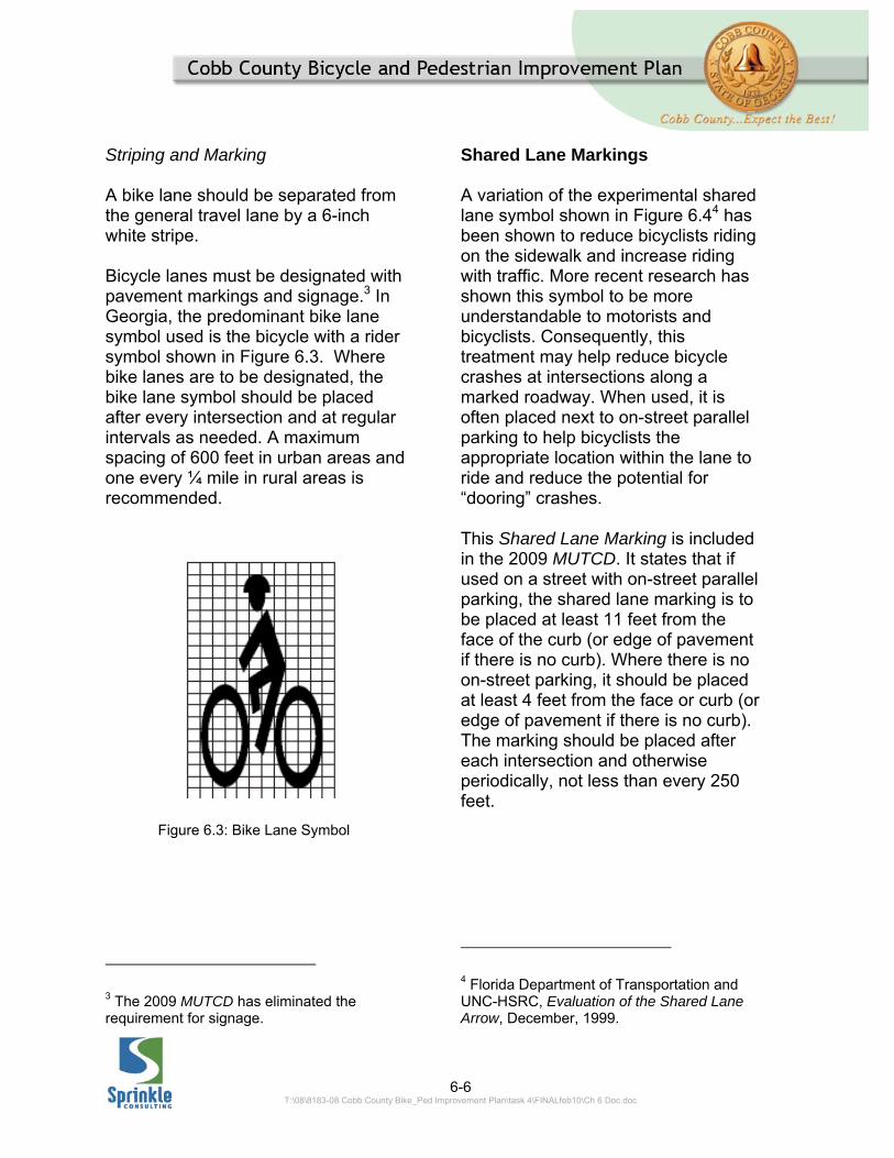
Striping and Marking A bike lane should be separated from the general travel lane by a 6-inch white stripe.
Bicycle lanes must be designated with pavement markings and signage.3 In Georgia, the predominant bike lane symbol used is the bicycle with a rider symbol shown in Figure 6.3. Where bike lanes are to be designated, the bike lane symbol should be placed after every intersection and at regular intervals as needed. A maximum spacing of 600 feet in urban areas and one every ¼ mile in rural areas is recommended.
3 The 2009 MUTCD has eliminated the requirement for signage.
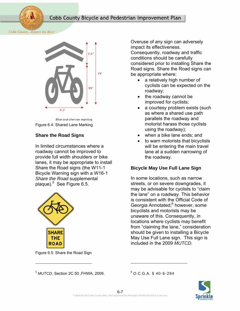
Shared Lane Markings A variation of the experimental shared lane symbol shown in Figure 6.44 has been shown to reduce bicyclists riding on the sidewalk and increase riding with traffic. More recent research has shown this symbol to be more understandable to motorists and bicyclists. Consequently, this treatment may help reduce bicycle crashes at intersections along a marked roadway. When used, it is often placed next to on-street parallel parking to help bicyclists the appropriate location within the lane to ride and reduce the potential for “dooring” crashes.
This Shared Lane Marking is included in the 2009 MUTCD. It states that if used on a street with on-street parallel parking, the shared lane marking is to be placed at least 11 feet from the face of the curb (or edge of pavement if there is no curb). Where there is no on-street parking, it should be placed at least 4 feet from the face or curb (or edge of pavement if there is no curb). The marking should be placed after each intersection and otherwise periodically, not less than every 250 feet.
4 Florida Department of Transportation and UNC-HSRC, Evaluation of the Shared Lane Arrow, December, 1999.
Figure 6.3: Bike Lane Symbol
6-7 T:\08\8183-08 Cobb County Bike_Ped Improvement Plan\task 4\FINALfeb10\Ch 6 Doc.doc
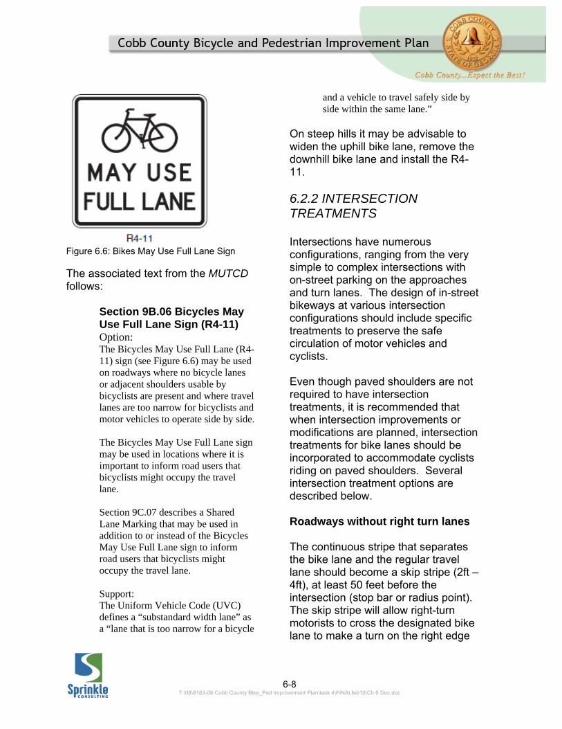
Share the Road Signs In limited circumstances where a roadway cannot be improved to provide full width shoulders or bike lanes, it may be appropriate to install Share the Road signs (the W11-1 Bicycle Warning sign with a W16-1 Share the Road supplemental plaque).5 See Figure 6.5.
5 MUTCD, Section 2C.50 ,FHWA, 2009.
Overuse of any sign can adversely impact its effectiveness. Consequently, roadway and traffic conditions should be carefully considered prior to installing Share the Road signs. Share the Road signs can be appropriate where:
a relatively high number of cyclists can be expected on the roadway;
the roadway cannot be improved for cyclists;
a courtesy problem exists (such as where a shared use path parallels the roadway and motorist harass those cyclists using the roadway);
when a bike lane ends; and to warn motorists that bicyclists
will be entering the main travel lane at a sudden narrowing of the roadway.
Bicycle May Use Full Lane Sign
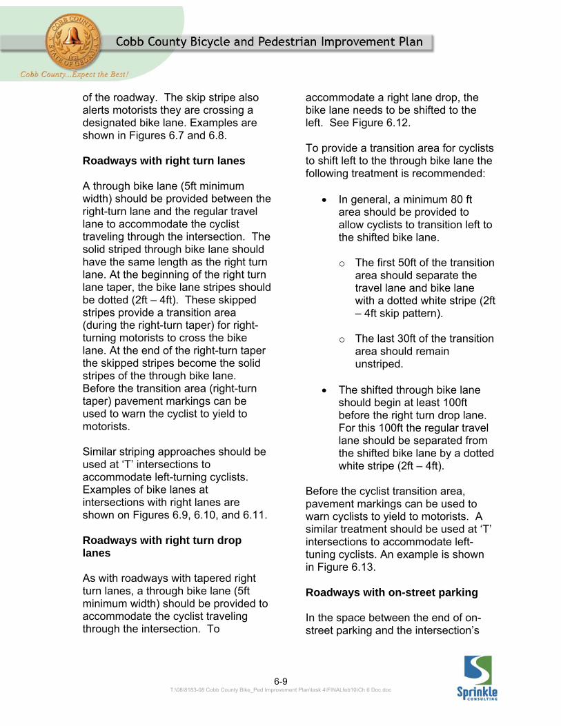
In some locations, such as narrow streets, or on severe downgrades, it may be advisable for cyclists to “claim the lane” on a roadway. This behavior is consistent with the Official Code of Georgia Annotated;6 however, some bicyclists and motorists may be unaware of this. Consequently, in locations where cyclists may benefit from “claiming the lane,” consideration should be given to installing a Bicycle May Use Full Lane sign. This sign is included in the 2009 MUTCD.
6 O.C.G.A. § 40-6-294
Figure 6.4: Shared Lane Marking
Figure 6.5: Share the Road Sign
6-8 T:\08\8183-08 Cobb County Bike_Ped Improvement Plan\task 4\FINALfeb10\Ch 6 Doc.doc
Figure 6.6: Bikes May Use Full Lane Sign The associated text from the MUTCD follows:
Section 9B.06 Bicycles May Use Full Lane Sign (R4-11) Option: The Bicycles May Use Full Lane (R4-11) sign (see Figure 6.6) may be used on roadways where no bicycle lanes or adjacent shoulders usable by bicyclists are present and where travel lanes are too narrow for bicyclists and motor vehicles to operate side by side. The Bicycles May Use Full Lane sign may be used in locations where it is important to inform road users that bicyclists might occupy the travel lane. Section 9C.07 describes a Shared Lane Marking that may be used in addition to or instead of the Bicycles May Use Full Lane sign to inform road users that bicyclists might occupy the travel lane. Support: The Uniform Vehicle Code (UVC) defines a “substandard width lane” as a “lane that is too narrow for a bicycle
and a vehicle to travel safely side by side within the same lane.”
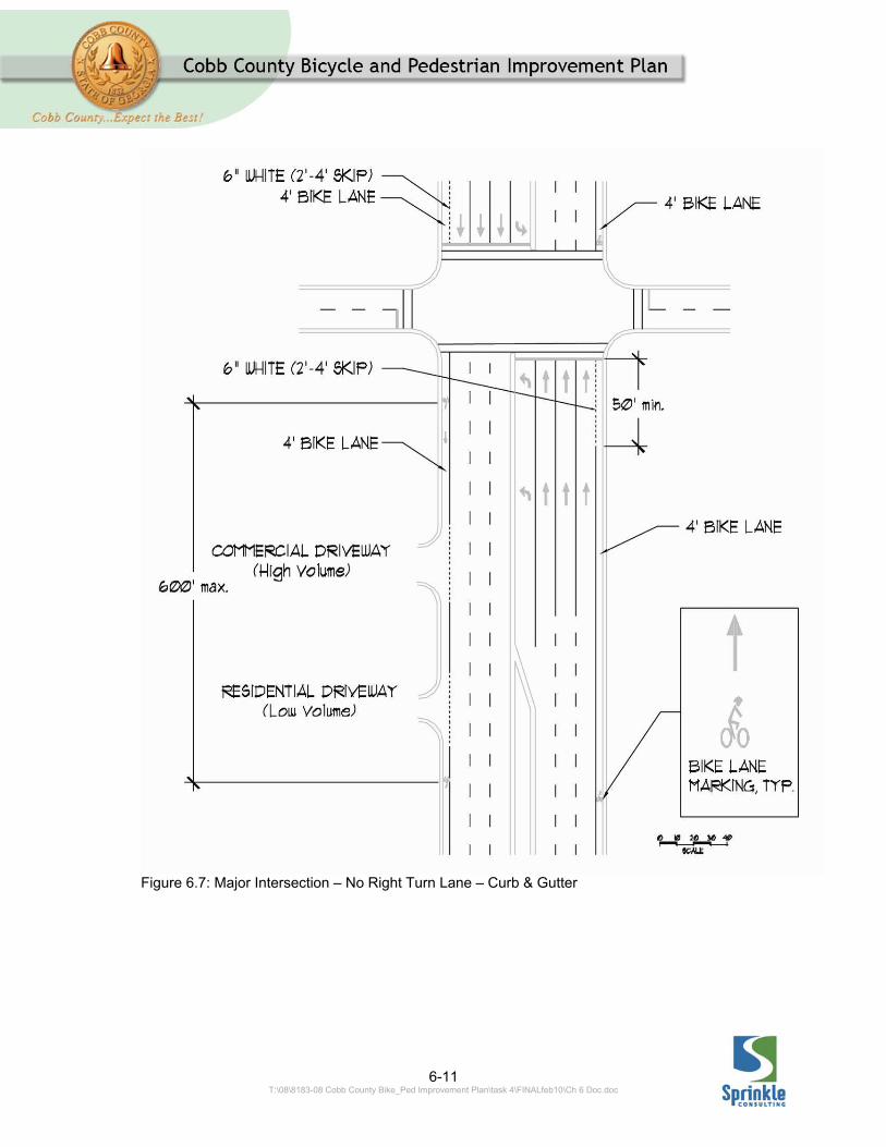
On steep hills it may be advisable to widen the uphill bike lane, remove the downhill bike lane and install the R4-11. 6.2.2 INTERSECTION TREATMENTS Intersections have numerous configurations, ranging from the very simple to complex intersections with on-street parking on the approaches and turn lanes. The design of in-street bikeways at various intersection configurations should include specific treatments to preserve the safe circulation of motor vehicles and cyclists. Even though paved shoulders are not required to have intersection treatments, it is recommended that when intersection improvements or modifications are planned, intersection treatments for bike lanes should be incorporated to accommodate cyclists riding on paved shoulders. Several intersection treatment options are described below. Roadways without right turn lanes The continuous stripe that separates the bike lane and the regular travel lane should become a skip stripe (2ft – 4ft), at least 50 feet before the intersection (stop bar or radius point). The skip stripe will allow right-turn motorists to cross the designated bike lane to make a turn on the right edge
6-9 T:\08\8183-08 Cobb County Bike_Ped Improvement Plan\task 4\FINALfeb10\Ch 6 Doc.doc
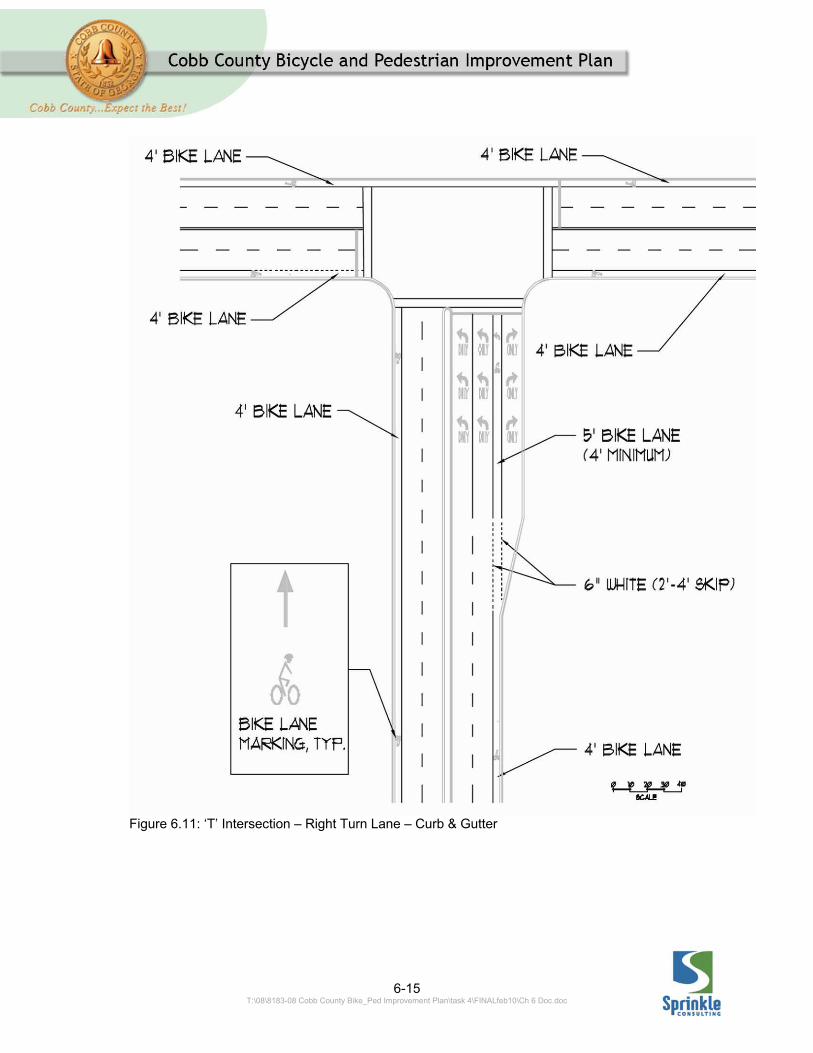
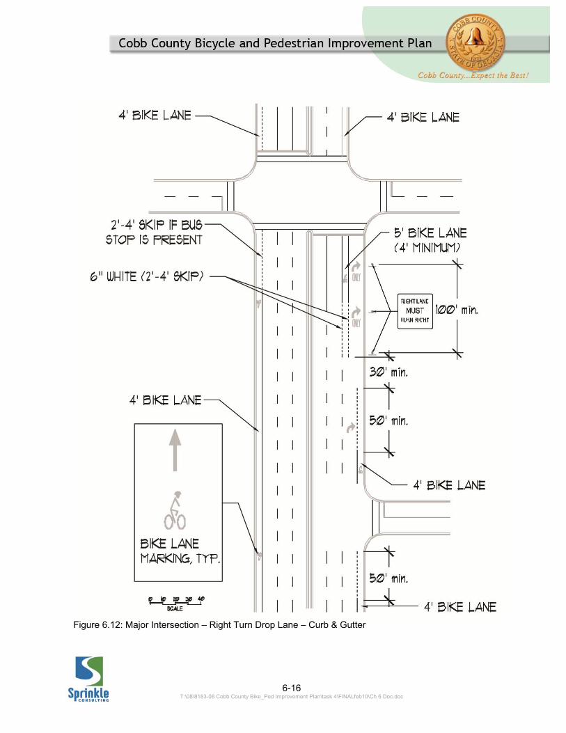
of the roadway. The skip stripe also alerts motorists they are crossing a designated bike lane. Examples are shown in Figures 6.7 and 6.8. Roadways with right turn lanes A through bike lane (5ft minimum width) should be provided between the right-turn lane and the regular travel lane to accommodate the cyclist traveling through the intersection. The solid striped through bike lane should have the same length as the right turn lane. At the beginning of the right turn lane taper, the bike lane stripes should be dotted (2ft – 4ft). These skipped stripes provide a transition area (during the right-turn taper) for right-turning motorists to cross the bike lane. At the end of the right-turn taper the skipped stripes become the solid stripes of the through bike lane. Before the transition area (right-turn taper) pavement markings can be used to warn the cyclist to yield to motorists. Similar striping approaches should be used at ‘T’ intersections to accommodate left-turning cyclists. Examples of bike lanes at intersections with right lanes are shown on Figures 6.9, 6.10, and 6.11. Roadways with right turn drop lanes As with roadways with tapered right turn lanes, a through bike lane (5ft minimum width) should be provided to accommodate the cyclist traveling through the intersection. To
accommodate a right lane drop, the bike lane needs to be shifted to the left. See Figure 6.12. To provide a transition area for cyclists to shift left to the through bike lane the following treatment is recommended:
In general, a minimum 80 ft area should be provided to allow cyclists to transition left to the shifted bike lane.
o The first 50ft of the transition
area should separate the travel lane and bike lane with a dotted white stripe (2ft – 4ft skip pattern).
o The last 30ft of the transition
area should remain unstriped.
The shifted through bike lane
should begin at least 100ft before the right turn drop lane. For this 100ft the regular travel lane should be separated from the shifted bike lane by a dotted white stripe (2ft – 4ft).
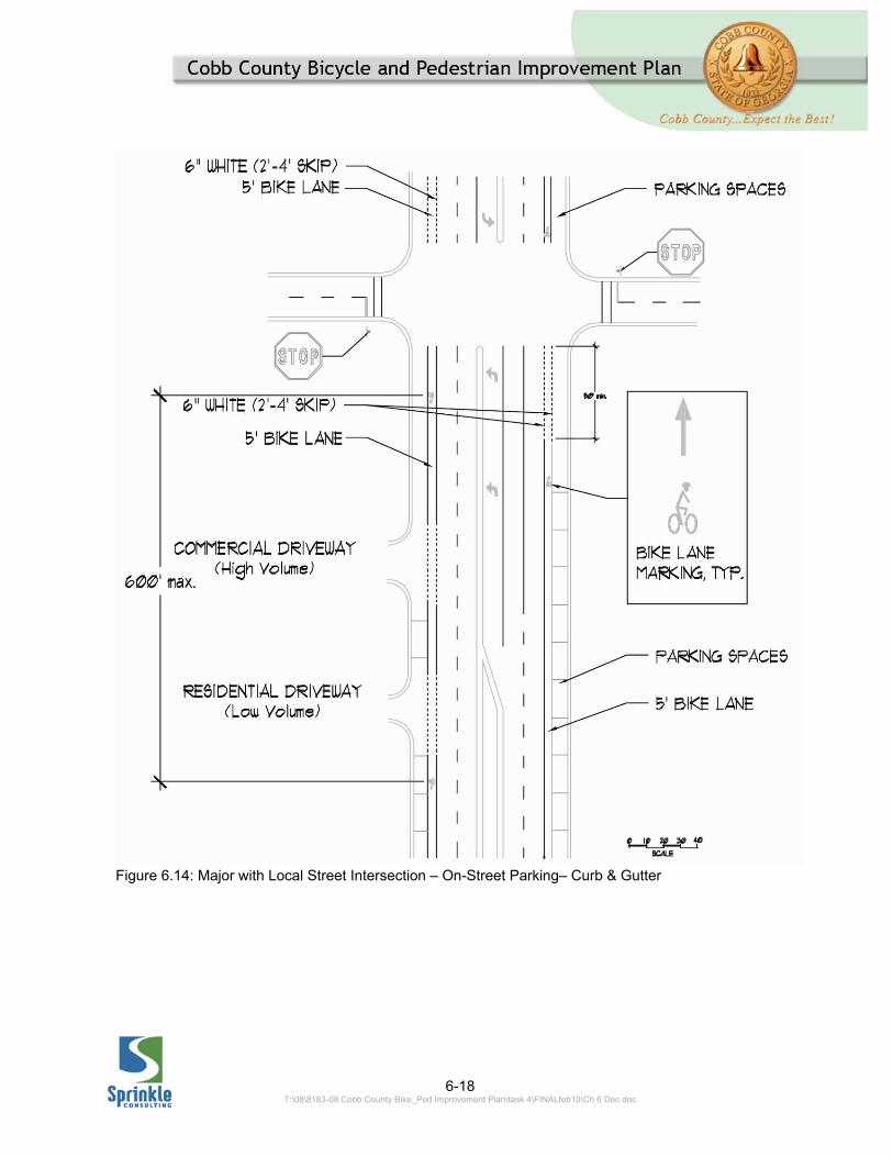
Before the cyclist transition area, pavement markings can be used to warn cyclists to yield to motorists. A similar treatment should be used at ‘T’ intersections to accommodate left-tuning cyclists. An example is shown in Figure 6.13. Roadways with on-street parking In the space between the end of on-street parking and the intersection’s
6-10 T:\08\8183-08 Cobb County Bike_Ped Improvement Plan\task 4\FINALfeb10\Ch 6 Doc.doc
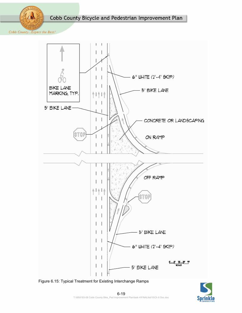
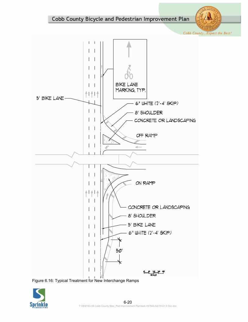
stop bar the bike lane should be delineated by dotted stripes on both sides (2ft – 4ft skip pattern). A typical example is shown in 6.14. Roadways with right turn lanes and a shared through/right turn Designers should consider the confusion created for cyclists and motorists before using this type of intersection treatment. In roadways with designated bike lanes, it is recommended to avoid marking a through/right turn lane next to a right turn lane. Interchange areas Typical interchange areas in Cobb County have large radii on/off ramps. The large radii and long diverge and merge lanes associated with these intersection configurations are problematic for bicyclists as they create weaving areas with high speed motor vehicle traffic. To accommodate cyclists in these types of interchanges the treatment shown on Figure 6.15 is recommended. This treatment provides cyclists with an option to continue parallel to the direction of motorist traffic or to cross the on/off ramp traffic at a right angle. For the development of new interchanges in urban type areas, a more compact design with smaller radii, in accordance to AASHTO guidelines, is recommended. To accommodate cyclists within the more compact interchanges implement the treatment shown in Figure 6.16.
6-11 T:\08\8183-08 Cobb County Bike_Ped Improvement Plan\task 4\FINALfeb10\Ch 6 Doc.doc
Figure 6.7: Major Intersection – No Right Turn Lane – Curb & Gutter

6-12 T:\08\8183-08 Cobb County Bike_Ped Improvement Plan\task 4\FINALfeb10\Ch 6 Doc.doc
Figure 6.8: Major with Local Street Intersection – No Right Turn Lane – Paved Shoulder

6-13 T:\08\8183-08 Cobb County Bike_Ped Improvement Plan\task 4\FINALfeb10\Ch 6 Doc.doc
Figure 6.9: Major Intersection – Right Turn Lane – Curb & Gutter

6-14 T:\08\8183-08 Cobb County Bike_Ped Improvement Plan\task 4\FINALfeb10\Ch 6 Doc.doc
Figure 6.10: Major Intersection – Right Turn Lane – Paved Shoulder
6-15 T:\08\8183-08 Cobb County Bike_Ped Improvement Plan\task 4\FINALfeb10\Ch 6 Doc.doc
Figure 6.11: ‘T’ Intersection – Right Turn Lane – Curb & Gutter
6-16 T:\08\8183-08 Cobb County Bike_Ped Improvement Plan\task 4\FINALfeb10\Ch 6 Doc.doc
Figure 6.12: Major Intersection – Right Turn Drop Lane – Curb & Gutter

6-17 T:\08\8183-08 Cobb County Bike_Ped Improvement Plan\task 4\FINALfeb10\Ch 6 Doc.doc
Figure 6.13: ‘T’ Intersection – Right Turn Drop Lane – Curb & Gutter
6-18 T:\08\8183-08 Cobb County Bike_Ped Improvement Plan\task 4\FINALfeb10\Ch 6 Doc.doc
Figure 6.14: Major with Local Street Intersection – On-Street Parking– Curb & Gutter
6-19 T:\08\8183-08 Cobb County Bike_Ped Improvement Plan\task 4\FINALfeb10\Ch 6 Doc.doc
Figure 6.15: Typical Treatment for Existing Interchange Ramps
6-20 T:\08\8183-08 Cobb County Bike_Ped Improvement Plan\task 4\FINALfeb10\Ch 6 Doc.doc
Figure 6.16: Typical Treatment for New Interchange Ramps
6-21 T:\08\8183-08 Cobb County Bike_Ped Improvement Plan\task 4\FINALfeb10\Ch 6 Doc.doc
6.2.3 TRAFFIC SIGNALS On most roadways, cyclists can cross intersections under the same signal phase as motorists. However, on occasion, modified signal timing or additional traffic control devices may be appropriate. Timing of traffic signals Cyclists are at the greatest risk during periods of low traffic flow and clearance intervals. Signals should be designed to provide an adequate clearance interval for bicyclists who enter at the end of the green signal phase and a total crossing time long enough to accommodate cyclists starting up on a new green signal phase. Yellow change intervals adequate for motorists are usually adequate for cyclists. The AASHTO Greenbook7 provides the following equation to calculate the total clearance interval (yellow change interval plus red clearance interval):
v
lw
b
vtry rcleaer
2
y = yellow interval, sec rclear = red clearance interval, sec tr = reaction time (1.0 sec) v = bicyclist speed, fps8 b = bicycle braking deceleration (4 to 8 ft/s2) w = width of crossing, ft l = length of bicycle, 6 ft 7 A Policy on the Geometric Design of Highways and Streets, 2004, AASHTO. 8 The AASHTO Bike Guide, P 65, has a typographical error stating speeds are in mph
Detection of bicycles at signalized intersections Just as with detection for motor vehicles, the detection of bicyclists at intersections is an important aspect of intersection design. This section describes the importance of providing detection that works for all vehicles (motor vehicles and bikes) in the roadway and strategies for making signals responsive to the presence of bicycles. Approximately 98% of cyclists should be able to clear signals timed for a cyclist speed of 6 mph. If this interval is longer than the allowed by local code, the longest available clearance interval should be used. A bicyclist needs enough time to react, accelerate and cross the intersection when approaching a green signal. The AASHTO Greenbook (P 65) provides an equation to determine the minimum green time; however, this equation does not accurately represent the required minimum time for bicyclists to clear an intersection. A more accurate equation for intersections up to 144 feet wide is provided below:
a
lwtryg rclear
)(2
g = minimum green y = yellow interval, sec rclear = red clearance interval, sec tr = reaction time (2.5 sec) w = width of crossing, ft l = length of bicycle, 6 ft a = bicycle acceleration (1.5 – 3 ft/s2)

6-22 T:\08\8183-08 Cobb County Bike_Ped Improvement Plan\task 4\FINALfeb10\Ch 6 Doc.doc
Actual field observations should be taken prior to making any adjustments to the minimum green or clearance intervals. Acute angle intersections require longer crossing times for cyclists. For compliance with traffic laws and cyclist’s safety, bicycles should be detected at traffic-actuated signals. Efforts should be made to ensure that signal detection devices are capable of detecting bicycles. Even though detectors that have been placed for vehicular traffic can usually detect bicycles, it is recommended to mark the road surface to indicate to cyclists the optimum location for bicycle detection. Figure 6.17 shows a standard pavement symbol which should be placed at the location of the loop detector to notify the cyclist where to stop.
The MUTC requires traffic signals be adjusted to consider the needs of bicycles.9 Of equal importance is the fact that signals which cannot detect bicyclists impact both the safety of cyclists and the attitudes of motorists. The MUTCD states: Standard: At installations where visibility-limited signal faces are used, signal faces shall be adjusted so bicyclists for whom the indications are intended can see the signal indications. If the visibility-limited signal faces cannot be aimed to serve the bicyclist, then separate signal faces shall be provided for the bicyclist. On bikeways, signal timing and actuation shall be reviewed and adjusted to consider the needs of bicyclists. It is important that bicyclists riding on roadways should be able to see the traffic signals for their approaches. This discussion, however, focuses on the second part of the MUTCD standard, the requirement to review and adjust signal actuation in consideration of the needs of bicyclists. Non-responsive signals, at which cyclists cannot get a green signal indication, can cause unsafe behaviors 9 MUTCD, Section 9D.02 Signal Operations for Bicycles, FHWA, Washington, D.C., 2009.
Figure 6.17: Bicycle Detector Pavement Marking
6-23 T:\08\8183-08 Cobb County Bike_Ped Improvement Plan\task 4\FINALfeb10\Ch 6 Doc.doc
by cyclists. Bicyclists can be frustrated by traffic signals which will not detect their bicycles. Non-responsive signals can cause significant delays, and when delayed long enough bicyclists will typically ride through the red signal. While this is not an illegal behavior,10 it can contribute to cyclists choosing to disregard other signals which might actually be responsive to their presence. This conditioned disregard for signals can lead to crashes. Signals which do not respond to the presence of bicycles can also adversely affect motorists’ attitudes toward bicyclists. Motorists’ observation of cyclists proceeding through red signals reinforces the oft-held belief that most cyclists are scofflaws with no regard for the rules of the road and/or even that cycling is not a legitimate mode of transportation on the roadway. Traffic signals are usually installed because there are relatively high traffic volumes on both the main road and Side Street. This means that throughout most of the day, and most of the week, there is an adequate volume of motor vehicles on any particular approach to call the green
10 316.1235 (FS) Vehicle approaching intersection in which traffic lights are inoperative.‐‐The driver of a vehicle approaching an intersection in which the traffic lights are inoperative shall stop in the manner indicated in s. 316.123(2) for approaching a stop intersection. In the event that only some of the traffic lights within an intersection are inoperative, the driver of a vehicle approaching an inoperative light shall stop in the above‐prescribed manner.
signal. However, at some intersections, or during off-peak times (i.e., at night, in the early morning, on weekends) this may not be the case. In these situations, the signal detection hardware should be configured so that bicyclists can be detected. The following section identifies situations where the detection of bicyclists is an important consideration, how signal loops detect bicyclists, and how signalized intersections can be improved to consider the needs of bicyclists. Important locations for bicyclist detection Just as detection of motor vehicles is not necessary for all movement approaches to signalized intersections, the same is true for the detection of bicycles. A discussion of which approaches may or may not need to be able to detect bicycles is provided below: Through movements: Typically, signals along arterial roadways are programmed to “rest on green” for the arterial roadway. This means that if the signal hardware does not detect a vehicle on a side street approach, the signal facing the arterial roadway will remain green indefinitely. At other roadway intersections, however, signals are programmed for “automatic recall,” which gives each approach through movement a green signal every cycle, whether a vehicle is detected or not. On arterial roadways employing either if these two approaches to signal timing, it is
6-24 T:\08\8183-08 Cobb County Bike_Ped Improvement Plan\task 4\FINALfeb10\Ch 6 Doc.doc
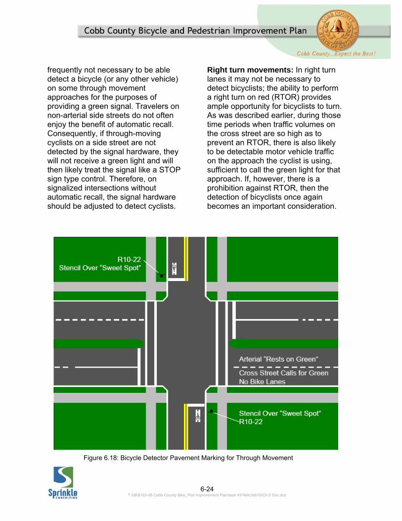
frequently not necessary to be able detect a bicycle (or any other vehicle) on some through movement approaches for the purposes of providing a green signal. Travelers on non-arterial side streets do not often enjoy the benefit of automatic recall. Consequently, if through-moving cyclists on a side street are not detected by the signal hardware, they will not receive a green light and will then likely treat the signal like a STOP sign type control. Therefore, on signalized intersections without automatic recall, the signal hardware should be adjusted to detect cyclists.
Right turn movements: In right turn lanes it may not be necessary to detect bicyclists; the ability to perform a right turn on red (RTOR) provides ample opportunity for bicyclists to turn. As was described earlier, during those time periods when traffic volumes on the cross street are so high as to prevent an RTOR, there is also likely to be detectable motor vehicle traffic on the approach the cyclist is using, sufficient to call the green light for that approach. If, however, there is a prohibition against RTOR, then the detection of bicyclists once again becomes an important consideration.
Figure 6.18: Bicycle Detector Pavement Marking for Through Movement
6-25 T:\08\8183-08 Cobb County Bike_Ped Improvement Plan\task 4\FINALfeb10\Ch 6 Doc.doc
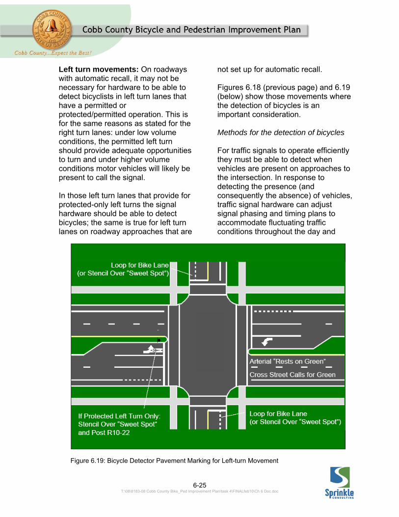
Left turn movements: On roadways with automatic recall, it may not be necessary for hardware to be able to detect bicyclists in left turn lanes that have a permitted or protected/permitted operation. This is for the same reasons as stated for the right turn lanes: under low volume conditions, the permitted left turn should provide adequate opportunities to turn and under higher volume conditions motor vehicles will likely be present to call the signal. In those left turn lanes that provide for protected-only left turns the signal hardware should be able to detect bicycles; the same is true for left turn lanes on roadway approaches that are
not set up for automatic recall. Figures 6.18 (previous page) and 6.19 (below) show those movements where the detection of bicycles is an important consideration. Methods for the detection of bicycles For traffic signals to operate efficiently they must be able to detect when vehicles are present on approaches to the intersection. In response to detecting the presence (and consequently the absence) of vehicles, traffic signal hardware can adjust signal phasing and timing plans to accommodate fluctuating traffic conditions throughout the day and
Figure 6.19: Bicycle Detector Pavement Marking for Left-turn Movement
6-26 T:\08\8183-08 Cobb County Bike_Ped Improvement Plan\task 4\FINALfeb10\Ch 6 Doc.doc
week. Inefficient signal operations can arise when vehicle detection hardware is not operating optimally, such as when a loop fails. When this happens, the detector hardware will usually compensate by providing an automatic recall to the movement formerly monitored by the failed detector; this means that the lane over the failed loop will receive a green light during every cycle, whether a vehicle is there or not. Alternatively, there are some signal loop installations which may detect cars, but do not detect some trucks, motorcycles or bicycles. If they are not detected, these vehicles may not receive a green light. This section describes common detector types and how their detection of bicycles can be optimized. Inductive loops: The most common type of vehicle detection hardware is the inductive loop. The loop consists of a wire (or several wires) embedded into the roadway. A very low voltage current runs continuously through the loop; whenever a conductive object enters the electrical field around the loop, the loop’s inductance is altered. The detector hardware senses this change in inductance and interprets it as a vehicle over the loop.11
11 It is important to note that induction loops do not detect changes in the magnetic field and therefore a bicycle need not be made of steel to be detected. Because aluminum is a better conductor than steel, aluminum bikes are actually are more easily detected by inductive loops than steel bikes.
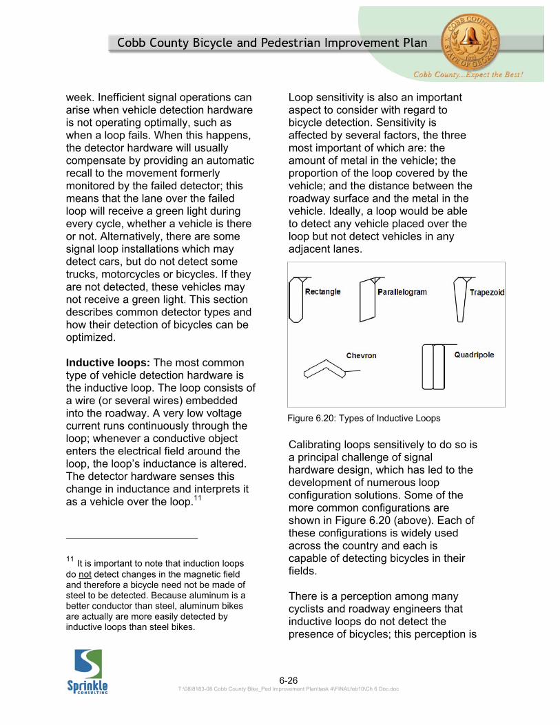
Loop sensitivity is also an important aspect to consider with regard to bicycle detection. Sensitivity is affected by several factors, the three most important of which are: the amount of metal in the vehicle; the proportion of the loop covered by the vehicle; and the distance between the roadway surface and the metal in the vehicle. Ideally, a loop would be able to detect any vehicle placed over the loop but not detect vehicles in any adjacent lanes.
Calibrating loops sensitively to do so is a principal challenge of signal hardware design, which has led to the development of numerous loop configuration solutions. Some of the more common configurations are shown in Figure 6.20 (above). Each of these configurations is widely used across the country and each is capable of detecting bicycles in their fields. There is a perception among many cyclists and roadway engineers that inductive loops do not detect the presence of bicycles; this perception is
Figure 6.20: Types of Inductive Loops
6-27 T:\08\8183-08 Cobb County Bike_Ped Improvement Plan\task 4\FINALfeb10\Ch 6 Doc.doc
often based on cyclists not waiting in an optimal spot for detection. Research has shown that inductive loops are highly reliable at detecting steel and aluminum bicycles when bicycles are in the proper position.12
There are two basic strategies to improve detection of bicycles: to direct bicyclists to the area of optimal loop sensitivity (“marking the sweet spot”) or to place new loops in spots where cyclists are likely to be waiting, such as in the bike lane or at the right edge of the pavement. It recommended that these strategies for optimizing loop detection of bicyclists be employed before investigating a substantial investment of new technology; the technology already in place around many local intersections is likely quite capable of detecting bicyclists. The following sections describe these two strategies. Marking the Sweet Spot: One of the simplest ways to facilitate the detection of bicyclists at traffic signals is to mark that spot on the roadway where a given loop will detect a bicycle. The MUTCD provides for a symbol that may be placed on the pavement to indicate the optimum position for a bicyclist to actuate the signal.13 Used in conjunction with the BICYCLE SIGNAL ACTUATION sign
12 See for example the FHWA report “Bicycle and Pedestrian Transportation,” prepared by SRF consulting in 2003, available on line at http://ntl.bts.gov/lib/23000/23300/23330/BikePedDetFinalReport.pdf 13 MUTCD, Section 9C.05 Bicycle Detector Symbol, FHWA, Washington, D.C., 2009.
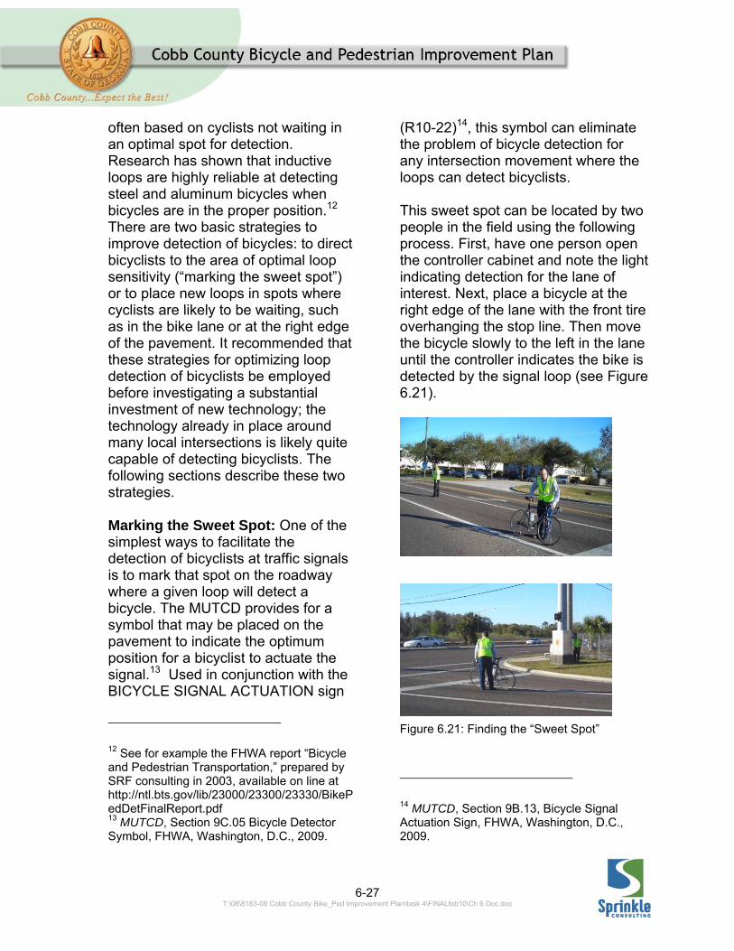
(R10-22)14, this symbol can eliminate the problem of bicycle detection for any intersection movement where the loops can detect bicyclists. This sweet spot can be located by two people in the field using the following process. First, have one person open the controller cabinet and note the light indicating detection for the lane of interest. Next, place a bicycle at the right edge of the lane with the front tire overhanging the stop line. Then move the bicycle slowly to the left in the lane until the controller indicates the bike is detected by the signal loop (see Figure 6.21).
14 MUTCD, Section 9B.13, Bicycle Signal Actuation Sign, FHWA, Washington, D.C., 2009.
Figure 6.21: Finding the “Sweet Spot”
6-28 T:\08\8183-08 Cobb County Bike_Ped Improvement Plan\task 4\FINALfeb10\Ch 6 Doc.doc
Continue moving the bike until the bicycle can no longer be detected. Finally, mark the pavement at the middle of this range of detection. In many cases an entire bicycle is not needed to locate the sweet spot, just a bicycle wheel may do. However, until it can be determined if a single wheel will be detected by local loops, an entire bike – and initially both a mountain bike and a road bike – may be appropriate for experimentation. Loops for Bike Lanes Placement of signal loops within bike lanes is not always necessary. As stated above, frequently bicycles only need to be detected in situations where no motor vehicle is present; in those situations, bicyclists could exit the bike lane and wait to be detected over the standard signal loop. Even so, changing lanes at an intersection to call for a signal change is not a normal vehicular behavior. Consequently, in the interest of providing consistent treatments and promoting consistent vehicular behavior, bike lane detection should still be considered at locations where signal change is unlikely without detection. The most commonly recommended loop type for bike lanes is a quadripole loop of reduced size. These loops are highly sensitive to objects in the area immediately above them, but detection falls off rapidly outside of this sensitivity field; this means that cars in adjacent lanes will not be detected. Quadripole loops, when placed in a
bike lane, typically detect within an area two feet wide by 10 feet long. 6.2.4 OBSTRUCTION MARKINGS Where obstructions are unavoidable a special treatment should be used to gain the attention of the approaching cyclists. Signs, reflectors, diagonal yellow markings or other treatments may be appropriate to alert bicyclists to potential obstructions. Figure 6.22 shows an example of an obstruction marking.
6.3 SHARED USE PATH DESIGN 6.3.1 DESIGN SPEED The design speed for a shared use path dictates numerous other design criteria values. Consequently, it is important to use the appropriate design speed – one that accommodates the design user, but does not needlessly constrain the designer – when designing shared use paths. According to the AASHTO Guide for the Development of Bicycle Facilities (referred to as the Bike Guide), shared use paths should be designed for a bicycle traveling at 20 mph.15
15 Guide for the development of Bicycle Facilities, pg. 36, American Association of State Highway and Transportation Officials, 1999.

6-29 T:\08\8183-08 Cobb County Bike_Ped Improvement Plan\task 4\FINALfeb10\Ch 6 Doc.doc
This design speed is based upon the idea that the occasional bicyclists can and will travel at 20 mph. Research performed subsequent to the adoption of the Bike Guide has established that these high speed cyclists represent a small proportion of the cyclists using shared use paths. These studies found that the 85 percentile speed for bicyclists using shared use paths ranges from 12.5 to 13.6 mph.16,17 Based upon the cited research, lower design speeds (than 20 mph) could be considered for some shared use paths or portions thereof. On regional trails, such as rail trails, it is appropriate to design to accommodate the higher speed cyclists. However, on trails specifically serving lower speed users reduced design speeds may be appropriate and provide some
16 Characteristics of Emerging Road and Trail Users and Their Safety, FHWA, 2005. 17 Operations of Shared Use Paths, FHWA, 2005.
benefits. These conditions are described in more detail in the following subsection. There are several conditions for which a reduced design speed would be appropriate and enhance a shared use path facility. On paths primarily serving school children, higher-speed cyclists may pose a hazard to the primary users. High speed cycling may not be appropriate on some “family friendly” routes. Commuter routes serving downtown areas should not be required to provide for high-speed cyclists. Path serving schools/local connections Paths serving elementary schools should not be designed to encourage high-speed cycling. Elementary school students, whether walking or bicycling, do not travel at high-speeds. They often do not ride bikes in straight lines; they tend to weave. They may be
Figure 6.22: Obstruction Marking Illustration

6-30 T:\08\8183-08 Cobb County Bike_Ped Improvement Plan\task 4\FINALfeb10\Ch 6 Doc.doc
unstable on bikes. Their behaviors are often unpredictable. Paths for elementary school students need not be designed to accommodate high-speed cyclist. Other pre-college students (middle, high school) riding to school also represent a class of shared use path that user could benefit from a reduced design speed. They tend to travel in groups and often do not ride in predictable ways. Whereas some cyclists will ride in uniform packs, students tend to be more fluid. They may shift positions within their groups considering only the other individuals in their groups without consistent scanning for other cyclists or pathway users. Student cyclists are more likely to be riding mountain bikes than road bikes, resulting in lower speeds. Consequently, a pathway serving students need not be designed to encourage high-speed cycling. Paths serving urbanized areas Just as urban and suburban roadways are designed to accommodate lower speed users than rural roads, it may be appropriate to allow for lower design speeds on paths in urbanized areas. In urbanized areas, the number of conflicts along pathways increases. Congestion, along the pathway often increases as well. Additionally, increased signal frequency tends to reduce the potential for high speed travel along pathways. Furthermore, as development becomes denser, the number of pedestrians using a pathway may increase causing
additional potential conflicts. These factors suggest that lower operating speeds, and thus design speeds, should be encouraged on pathways in urbanized areas. Recommended design speeds Table 6.1 provides recommended design speeds for shared use paths in Cobb County:
Facility type Recommended Design Speed
Rural path, independent
alignment 20 mph
Elementary school path
10 mph
Middle/high school path
15 mph
Local connectors
15 mph
Urban pathway 15 mph
Table 6.1: Recommended Design Speeds for Shared Used Paths
On paths with significant downgrades exceeding 4% a design speed 10 mph higher than that shown in the above table should be used.
6-31 T:\08\8183-08 Cobb County Bike_Ped Improvement Plan\task 4\FINALfeb10\Ch 6 Doc.doc
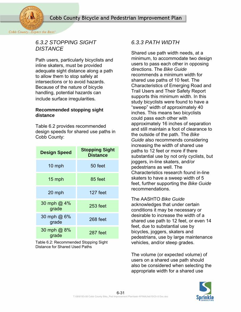
6.3.2 STOPPING SIGHT DISTANCE Path users, particularly bicyclists and inline skaters, must be provided adequate sight distance along a path to allow them to stop safely at intersections or to avoid hazards. Because of the nature of bicycle handling, potential hazards can include surface irregularities. Recommended stopping sight distance Table 6.2 provides recommended design speeds for shared use paths in Cobb County:
Design Speed Stopping Sight
Distance
10 mph 50 feet
15 mph 85 feet
20 mph 127 feet
30 mph @ 4% grade
253 feet
30 mph @ 6% grade
268 feet
30 mph @ 8% grade
287 feet
Table 6.2: Recommended Stopping Sight Distance for Shared Used Paths
6.3.3 PATH WIDTH
Shared use path width needs, at a minimum, to accommodate two design users to pass each other in opposing directions. The Bike Guide recommends a minimum width for shared use paths of 10 feet. The Characteristics of Emerging Road and Trail Users and Their Safety Report supports this minimum width. In this study bicyclists were found to have a “sweep” width of approximately 40 inches. This means two bicyclists could pass each other with approximately 16 inches of separation and still maintain a foot of clearance to the outside of the path. The Bike Guide also recommends considering increasing the width of shared use paths to 12 feet or more if there substantial use by not only cyclists, but joggers, in-line skaters, and/or pedestrians as well. The Characteristics research found in-line skaters to have a sweep width of 5 feet, further supporting the Bike Guide recommendations.
The AASHTO Bike Guide acknowledges that under certain conditions it may be necessary or desirable to increase the width of a shared use path to 12 feet, or even 14 feet, due to substantial use by bicycles, joggers, skaters and pedestrians, use by large maintenance vehicles, and/or steep grades.
The volume (or expected volume) of users on a shared use path should also be considered when selecting the appropriate width for a shared use
6-32 T:\08\8183-08 Cobb County Bike_Ped Improvement Plan\task 4\FINALfeb10\Ch 6 Doc.doc
path. The FHWA report Evaluation of Safety, Design, and Operation of Shared use Paths—Final Report18 provides a methodology for calculating the level of service for shared use paths based upon the number and type of users and the width of the path. The Bike Guide also recognizes that under some conditions it may be necessary to reduce a shared use path’s width to a minimum of 8 feet. According to AASHTO, this reduced should only be used where –
Bicycle traffic is expected to be low, even on peak days or during peak hours,
Pedestrian use of the facility is not expected to be more than occasional,
There will be good horizontal and vertical alignment providing safe and frequent passing opportunities, and
During normal maintenance activities the path will not be subjected to maintenance vehicle loading conditions that would cause pavement edge damage.
Some research suggests that the width of a path also influences the speed of the users on the path. Narrower paths appear to result in reduced travel speeds.
18 Evaluation of Safety, Design, and Operation of Shared use Paths— Final Report, FHWA, 2006.
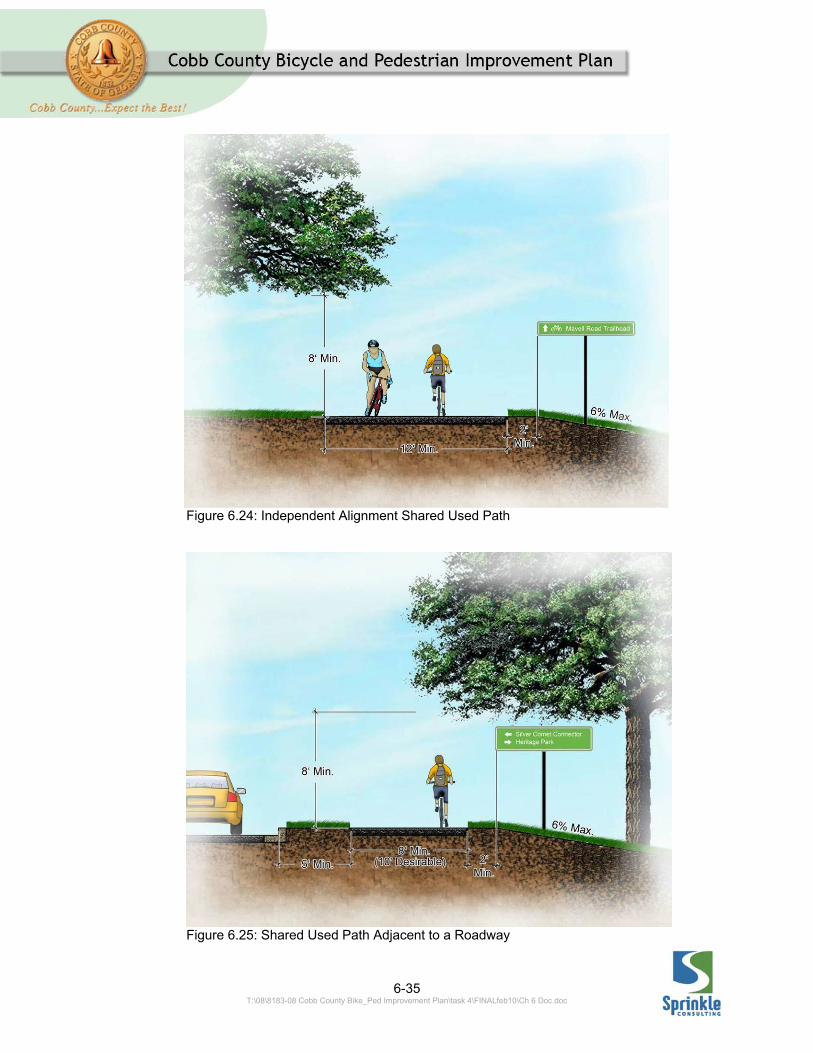
While it is understood that there will be instances in which the minimum widths stated below cannot be achieved, the following recommended widths should be provided whenever possible. Independent alignment shared use paths An independent alignment shared use path is one which does not closely parallel a roadway. Rail-trails are the most frequently thought of type of independent alignment shared use path, but these facilities may be located along utility easements, undeveloped platted roadways, or other exclusive rights of way. Independent shared use paths are typically quite long and well used by a myriad of user types – cyclists, skaters, joggers with dogs, adults on tricycles, kids, etc. Often they experience high volumes during peak activity periods. Users tend to be a mix of lower and higher speed users making it important to provide passing opportunities. Adequate width should be provided on these facilities to accommodate the various user types and speeds. To accommodate higher design speeds, multiple user types and higher volumes of users, the recommended minimum width for an independent alignment shared use path in Cobb County is 12 feet. A sketch of a typical cross section is shown in Figure 6.24 on page 6-33.
6-33 T:\08\8183-08 Cobb County Bike_Ped Improvement Plan\task 4\FINALfeb10\Ch 6 Doc.doc
School paths/local connectors A subset of the independent alignment shared use path is the local connector. Local connectors make short linkages between other facilities. Often these are represented by “short-cut” paths to schools or between neighborhoods. They may serve a limited number of users. School paths often function as (essentially) one-way facilities under peak volume conditions. School paths and local connectors should be a minimum of 8 feet wide, with 10 feet preferred when higher volumes are expected (see Evaluation of Safety, Design, and Operation of Shared use Paths—Final Report). Shared use paths adjacent to a roadway According to the AASHTO Guide for the Development of Bicycle Facilities, “when shared use paths are located immediately adjacent to a roadway,
some operational problems are likely to occur.” These include the following: They require one direction of
bicycle traffic to ride against motor vehicle traffic. This is contrary to motorists’ expectations and may result in motorists not noticing the “against traffic” cyclists until it is too late to prevent a crash.
Traffic exiting side streets or driveways may block the path.
Signs posted for motorists are facing away from cyclists riding against traffic.
The proximity of a path to a roadway may require barriers to keep cyclists from falling into the roadway or errant motor vehicles from running onto the path.
A further explanation of these and other points is provided in the
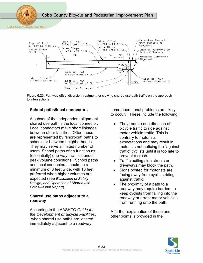
Figure 6.23: Pathway offset diversion treatment for slowing shared use path traffic on the approach to intersections
6-34 T:\08\8183-08 Cobb County Bike_Ped Improvement Plan\task 4\FINALfeb10\Ch 6 Doc.doc
AASHTO Bike Guide on pages 34 and 35.19 More recent research suggests there may be ways to mitigate some of these operational problems.20 Chief among the potential methods for reducing the operational problems of pathways adjacent to the roadways is reducing speeds along the facilities, particularly at intersections. A minimum width of 8 feet should be used for shared use paths adjacent to a roadway. A sketch of a typical cross section is shown in Figure 6.25 on page 6-33. For shared use paths adjacent to a roadway that serve as connectors for regional trails a minimum of 10 feet width is desirable; however, offsets (kinks) and neck-downs to slow down users may be appropriate on intersection approaches. A graphical example of such a treatment is shown in Figure 6.23. Where a pathway is located adjacent to a roadway, the path should be located a minimum of 5 feet from the edge of the shoulder or face of curb. If 5 feet cannot be obtained, a suitable barrier at least 42 inches high should be provided. However care must be taken that this barrier does not
19 AASHTO Guide for the Development of Bicycle Facilities, 1999, pp. 33-35. 20 Petritsch, Landis, Huang, and Challa. “Sidepath Safety Model - Bicycle Sidepath Design Factors Affecting Crash Rates”, Transportation Research Record 1982, Transportation Research Board, 2006.
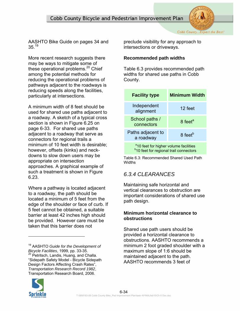
preclude visibility for any approach to intersections or driveways. Recommended path widths Table 6.3 provides recommended path widths for shared use paths in Cobb County.
Facility type Minimum Width
Independent alignment
12 feet
School paths / connectors
8 feeta
Paths adjacent to a roadway
8 feetb
a10 feet for higher volume facilities b10 feet for regional trail connectors
Table 6.3: Recommended Shared Used Path Widths
6.3.4 CLEARANCES
Maintaining safe horizontal and vertical clearances to obstruction are important considerations of shared use path design.
Minimum horizontal clearance to obstructions Shared use path users should be provided a horizontal clearance to obstructions. AASHTO recommends a minimum 2 foot graded shoulder with a maximum slope of 1:6 should be maintained adjacent to the path. AASHTO recommends 3 feet of
6-35 T:\08\8183-08 Cobb County Bike_Ped Improvement Plan\task 4\FINALfeb10\Ch 6 Doc.doc
Figure 6.24: Independent Alignment Shared Used Path
Figure 6.25: Shared Used Path Adjacent to a Roadway

6-36 T:\08\8183-08 Cobb County Bike_Ped Improvement Plan\task 4\FINALfeb10\Ch 6 Doc.doc
separation to vertical obstructions. A minimum of 5 feet should be maintained between shared use paths and embankments with greater than 3:1 slope. If this spacing cannot be maintained some sort of barrier should be considered. At a minimum, if an embankment with a slope greater than 3:1 is within 2 feet of the path and the drop-off exceeds 30 inches, an appropriate barrier should be installed. If a greater than 10-inch drop-off is located within 2 feet of the path it should be shielded. Minimum vertical clearance to obstructions A minimum vertical clearance of 8 feet above the surface of the shared use path should be maintained to overhead obstructions. A 10-foot vertical clearance is desirable. 6.3.5 HORIZONTAL ALIGNMENT
The horizontal alignment of shared use paths is dependent upon the facility design speeds. Maximum radii for paths are determined using the equation given on the bottom of page 37 in the AASHTO Bike Guide.
Recommended minimum turning path radii Table 6.4 provides recommended minimum radii for shared use paths in Cobb County.
Design Speed Radius
10 mph 23 feet (20 feet)
15 mph 55 feet (49 feet)
20 mph 102 feet (89 feet)
30 mph 316 feet (260
feet) The above dimensions assume a cross slope
of 2% to the outside of the curve. The reduced values shown in parentheses may be used with a 2% cross slope to the inside
of the curve.
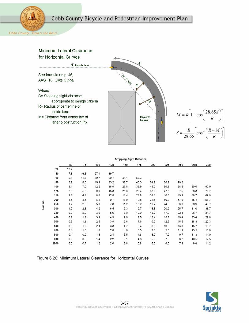
Table 6.4: Recommended Minimum Radii for Shared Used Path Minimum offset to visual obstructions When a visual obstruction is adjacent to a pathway, curves must be designed to maintain adequate sight distances around the obstructions. To do this, a minimum separation of the curved path to the potential visual obstruction must be maintained. Calculation of this minimum obstruction distance is calculated as shown in the graphic (Figure 6.26) and with the equations provided. A table of values is also provided.
6-37 T:\08\8183-08 Cobb County Bike_Ped Improvement Plan\task 4\FINALfeb10\Ch 6 Doc.doc
Figure 6.26: Minimum Lateral Clearance for Horizontal Curves

6-38 T:\08\8183-08 Cobb County Bike_Ped Improvement Plan\task 4\FINALfeb10\Ch 6 Doc.doc
6.3.6 VERTICAL ALIGNMENT Grade Cobb County has many areas where grades may play a significant role in the planning and design of shared use paths. For bicyclists, significant uphill grades can influence decisions in what routes they will ride or even if they will ride a bike at all. Consequently, whenever possible grades should be kept to a minimum. The AASHTO Bike Guide notes that grades greater than 5% are undesirable because the ascents are difficult for many bicyclists and the descents may cause some cyclists to exceed speeds at which they are competent. Additionally, the Americans with Disabilities Act Architectural Guidelines (ADAAG) state the maximum longitudinal grade for an accessible route is 5%; shared use paths must meet this criterion.21
In some instances, a greater than 5% grade cannot be avoided. The AASHTO Bike Guide provides desirable maximum lengths for grades steeper than 5%, these are shown in Table 6.5.
21The ADAAG has a provision for conditions of infeasibility. If the existing grade of a right-of-way exceeds 5%, following the existing grade is still allowed.
Grade Desired Maximum
Length
5-6% 800 ft
7% 400 ft
8% 300 ft
9% 200 ft
10% 100 ft
≥11% 50 ft
Table 6.5: Recommended Minimum Lengths for Grades on Shared Used Paths Where steeper than 5% grades are used the following design measures should be considered:
Increase clear recovery areas next to the path by providing wider shoulders and greater clearances to obstructions and embankments steeper than 3:1.
Increase the width of the path above the required minimum to provide additional “wobble” space for cyclists.
Use greater than the minimum allowable stopping sight distances.
Install rest areas 5 feet long at the desired maximum distances described above; these should be full width of the path and have a maximum of 5% slope in any direction.
6-39 T:\08\8183-08 Cobb County Bike_Ped Improvement Plan\task 4\FINALfeb10\Ch 6 Doc.doc
Install a Hill warning sign (W7-5) no less than 50 feet in advance of the slope.
Install centerline striping to better delineate the sides of the path.
At trailheads or informational kiosks, provide information (such as a profile under a map) of the grades on the trail.
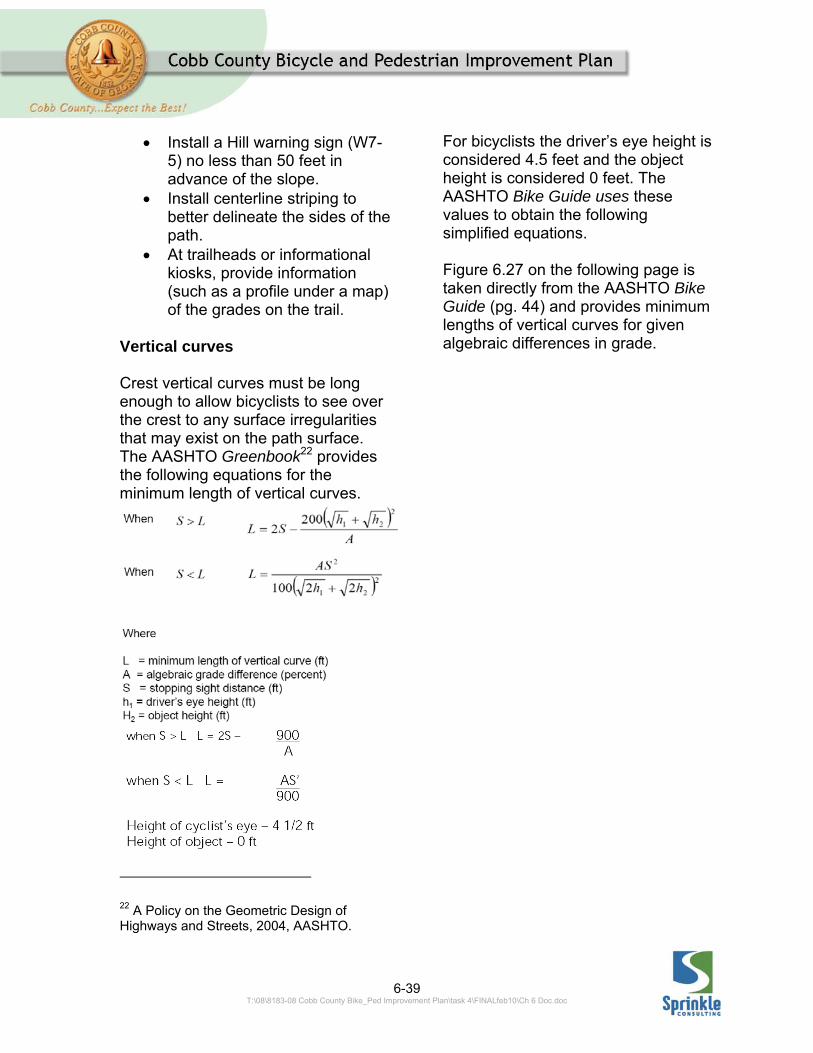
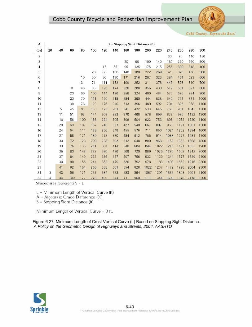
Vertical curves Crest vertical curves must be long enough to allow bicyclists to see over the crest to any surface irregularities that may exist on the path surface. The AASHTO Greenbook22 provides the following equations for the minimum length of vertical curves.
22 A Policy on the Geometric Design of Highways and Streets, 2004, AASHTO.
For bicyclists the driver’s eye height is considered 4.5 feet and the object height is considered 0 feet. The AASHTO Bike Guide uses these values to obtain the following simplified equations. Figure 6.27 on the following page is taken directly from the AASHTO Bike Guide (pg. 44) and provides minimum lengths of vertical curves for given algebraic differences in grade.
6-40 T:\08\8183-08 Cobb County Bike_Ped Improvement Plan\task 4\FINALfeb10\Ch 6 Doc.doc
Figure 6.27: Minimum Length of Crest Vertical Curve (L) Based on Stopping Sight Distance A Policy on the Geometric Design of Highways and Streets, 2004, AASHTO
6-41 T:\08\8183-08 Cobb County Bike_Ped Improvement Plan\task 4\FINALfeb10\Ch 6 Doc.doc
6.3.7 INTERSECTIONS OF SHARED USE PATHS AND ROADWAYS When at grade crossings occur between a shared use path and a roadway an intersection is created. Just as with any other intersection, several questions must be addressed when deciding upon how the intersection is to be designed. In particular, what specific traffic controls should be installed:
Which facility, road or path, should be the priority facility?
What is the least restrictive form of control that can be used (none, yield, stop, or signal)?
What treatments should be installed?
The following sections of these design guidelines address these questions. Assigning priority
Assigning priority at an intersection between a path and roadway will be decided differently for a path adjacent to a roadway and an independently aligned path.
Paths Adjacent to a Roadway
When a shared use path is built adjacent to a roadway, a sidepath, the sidepath should be given the same priority at intersections as the road it
parallels.23 Therefore, if the path parallels an arterial roadway and all side streets are STOP sign controlled to provide priority to the arterial, then the stop signs should be placed so that users of the path also have priority and are not required to stop.
Paths on Independent Alignments
When a shared use path intersects a roadway, a decision must be made as to which facility will a have priority and which will have to yield or stop. It should not be assumed that a roadway will always receive priority over a shared use path. According to the MUTCD –
Speed should not be the sole factor used to determine priority, as it is sometimes appropriate to give priority to a high-volume shared use path crossing a low-volume street, or to a regional shared use path crossing a minor collector street.
When placement of STOP or YIELD signs is considered, priority at a shared use path/roadway intersection should be assigned with consideration of the following:
A. Relative speeds of shared use path and roadway users; B. Relative volumes of shared use path and roadway traffic; and C. Relative importance of shared use path and roadway.
When priority is assigned, the least restrictive control that is appropriate should be placed on the lower priority
23 AASHTO Guide for Development of Bicycle Facilities, pg. 34.
6-42 T:\08\8183-08 Cobb County Bike_Ped Improvement Plan\task 4\FINALfeb10\Ch 6 Doc.doc
approaches. STOP signs should not be used where YIELD signs would be acceptable. [Provided adequate geometry exists for the needed visibility of approaching vehicles/users.]
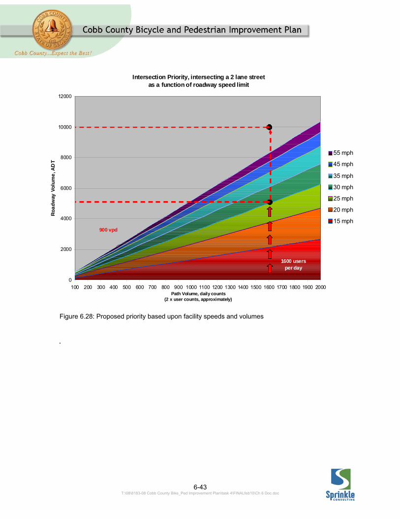
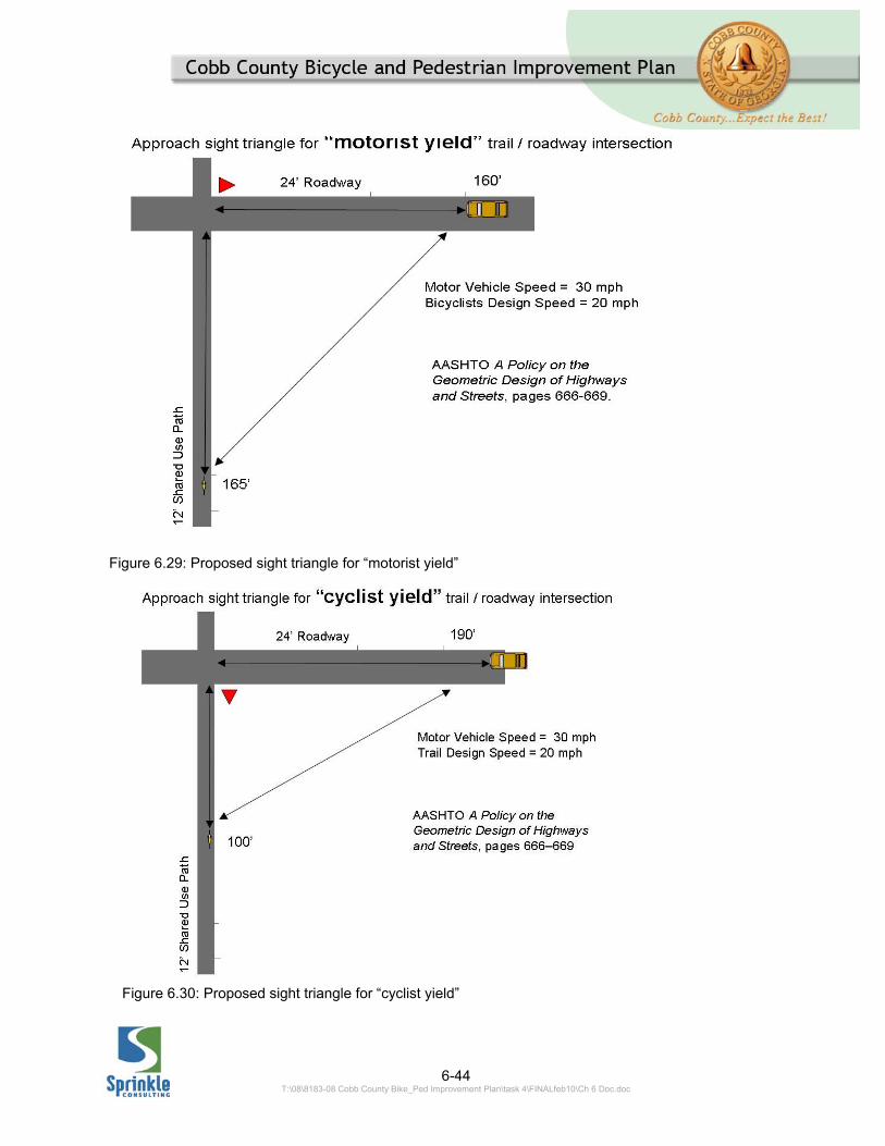
Given the above, the fact that a roadway may have higher speeds might be offset by the volume of the pathway being much higher than that of the roadway. A local roadway might also be considered a lower priority than a regional pathway. For two lane roadways, using the volumes and speeds of the pathway and its intersecting roadways is recommended to determine which facility should get priority. Figure 6.28 on the following page shows how this would be applied. Enter the graph with the roadway and path volumes, if the intercept is above the sloped line corresponding to the speed limit of the roadway, the roadway should receive the priority at the crossing. (Essentially the slope of each line is adjusted to reflect the proportionate speeds of the intersecting facilities.) Least Restrictive Form of Traffic Control The type of traffic control (Stop or Yield signs) required at an intersection is dependent upon intersection sight distances. Where possible Yield signs should be used as they are less restrictive than Stop signs and more representative of how path users are likely to behave. Overuse of Stop signs can lead to a lack of respect for the signs and unsafe assumptions by
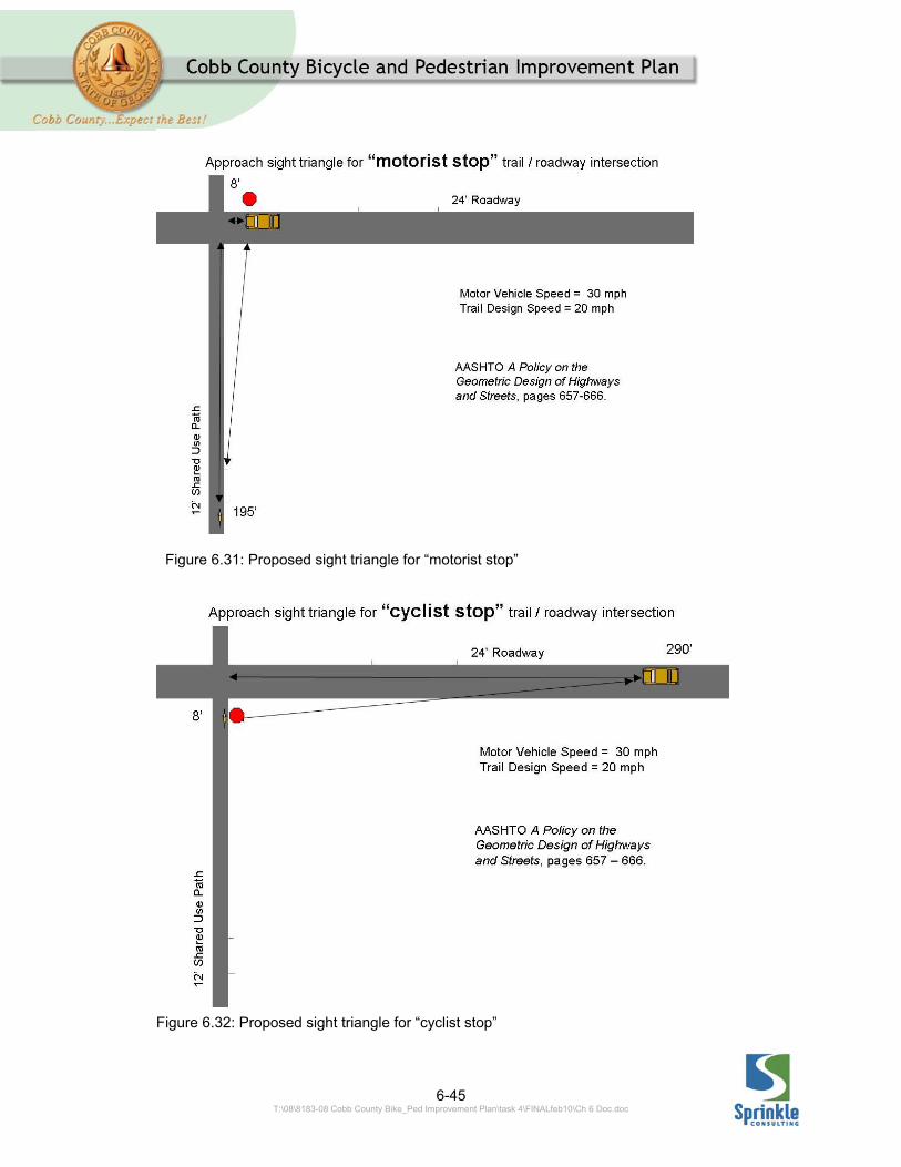
pathway users. This can further lead to the necessity for more authoritative traffic control devices where the cyclists really must stop to be safe. Available sight distances are the primary determining factor in deciding whether Yield sign or Stop sign is appropriate at an intersection. The criteria in AASHTO’s Green Book 24 should be used to determine if Yield control is acceptable. (Note, however, that significant clear right-of-way is needed and must be maintained for the use of “yield” control.) Examples of required sight distances are provided on pages 6-42 through 6-43.
24 A Policy on the Geometric Design of Highways and Streets, AASHTO, 2004, pp. 666-669
6-43 T:\08\8183-08 Cobb County Bike_Ped Improvement Plan\task 4\FINALfeb10\Ch 6 Doc.doc
.
Intersection Priority, intersecting a 2 lane streetas a function of roadway speed limit
0
2000
4000
6000
8000
10000
12000
100 200 300 400 500 600 700 800 900 1000 1100 1200 1300 1400 1500 1600 1700 1800 1900 2000Path Volume, daily counts
(2 x user counts, approximately)
Ro
ad
way
Vo
lum
e, A
DT
55 mph
45 mph
35 mph
30 mph
25 mph
20 mph
15 mph900 vpd
1600 users per day
Figure 6.28: Proposed priority based upon facility speeds and volumes
6-44 T:\08\8183-08 Cobb County Bike_Ped Improvement Plan\task 4\FINALfeb10\Ch 6 Doc.doc
Figure 6.29: Proposed sight triangle for “motorist yield”
Figure 6.30: Proposed sight triangle for “cyclist yield”
6-45 T:\08\8183-08 Cobb County Bike_Ped Improvement Plan\task 4\FINALfeb10\Ch 6 Doc.doc
Figure 6.31: Proposed sight triangle for “motorist stop”
Figure 6.32: Proposed sight triangle for “cyclist stop”
6-46 T:\08\8183-08 Cobb County Bike_Ped Improvement Plan\task 4\FINALfeb10\Ch 6 Doc.doc
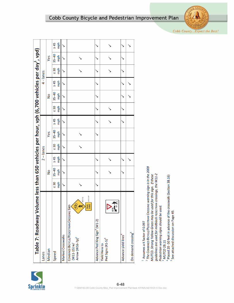
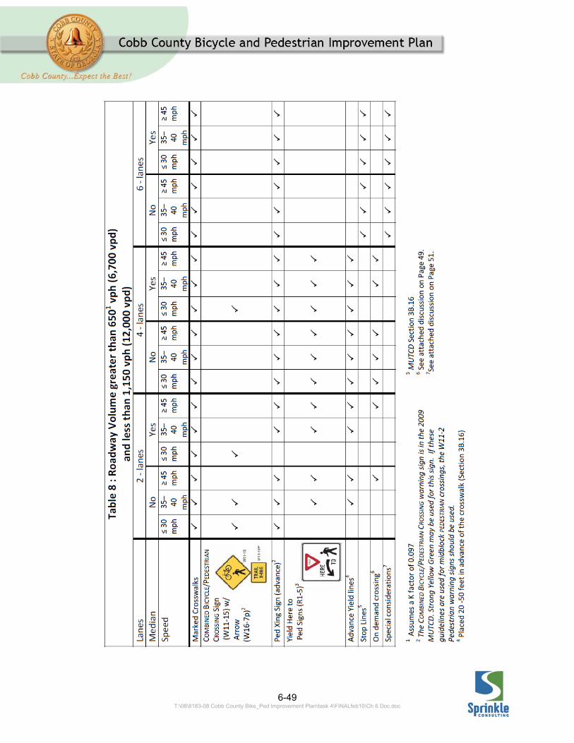
Supplemental Traffic Control Devices at Unsignalized Path Crossings Unsignalized Crossings The MUTCD provides information on what type of traffic control devices may be used at shared use path crossings. However, other than requiring crosswalk markings and Bicycle or Pedestrian Warning signs it provides no clear guidance about what conditions any particular traffic control devices are recommended to be used. The Atlanta Regional Commission Bicycle Transportation and Pedestrian Pathways Plan includes an appendix which makes specific recommendations with regard to what traffic control devices should be used for particular roadway/pathway conditions. While this document provides good guidance, recent developments on the national level with regard to FHWA acceptance of particular traffic control devices make it appropriate make some minor revisions to that document. The revised guidelines are provided below: For these guidelines, roadways were stratified into low-, medium-, and high-volume. The threshold volume for low- to medium-volume is determined using the amount of time a pedestrian can expect to wait for an adequate gap in traffic to cross the street. The medium- to high-volume threshold is based upon a midblock crossing safety study prepared by the University of North Carolina’s Highway Safety Research
Center.25 Depending on whether the street being crossed is low medium or high volume, the corresponding table, 6.6, would be referenced to determine the recommended traffic control devices for the crossing. In the application, one would determine the volume of traffic in the lanes being crossed and use Table 6.6 below to determine which table in the traffic control matrices to use.
Traffic Volume in Lanes Being
Crossed
> 6,700 vpd Table 6.7 6,700 – 12,000 vpd
Table 6.8
>12,000 vpd Table 6.9 vpd = vehicles per day Table 6.6: Volume Thresholds for the Crossing Treatments Guidelines The proposed traffic control matrices of appropriate treatments are shown on the following pages.
25 For a detailed discussion of how the low-, medium-, and high-volume roadway thresholds were obtained, please see 2007 Atlanta Region Bicycle Transportation & Pedestrian Walkways Plan (adopted September 26, 2007)
6-47 T:\08\8183-08 Cobb County Bike_Ped Improvement Plan\task 4\FINALfeb10\Ch 6 Doc.doc
General notes for applying the Crossing Treatment Guidelines Matrices 1. Each column in the table
represents a package of traffic control devices recommended for the specific crossing condition.
2. The designation of “YES” for the median assumes there is potential for installing a raised median at the crossing location and that one will be installed. Raised medians that can be used as pedestrian refuges (6 feet wide or wider in the direction of the roadway cross-section) will allow for less restrictive motor vehicle traffic controls to be used in conjunction with the midblock crossings. Wider refuge islands, 10 feet or more, should be considered to accommodate bicycle with trailers and recumbent bicycles.
3. On multi-lane roadways with medians on the approach, crossing signage for motorists should be placed in the medians as well as on the side of the roadway.
4. The use of Danish offsets (angled cuts through the median) should be considered at all crossings with raised medians for two reasons. First, the offset through the median directs the path users’ attention toward the traffic about to be crossed. Secondly, by providing an angled cut through the median, longer users (tandems, bicycles with trailers) may be better accommodated in a narrower median. Cattle-gate style crossings
which require two 90 degree turns in a short distance can restrict the passage of longer users; if used they should be carefully designed.
5. When advance yield lines are used on the approach roadways they should be used in conjunction with solid lane lines extending back the stopping sight distance from yield lines. This is to enable law enforcement officers to determine when a motorist fails to yield when he could have done so.
6. On six-lane, undivided roadways, strong consideration should be given to providing a grade-separated crossing of the roadway for pathway users. Until such time as this can be achieved, aggressive channelization should be used to divert pathway users to the nearest safe crossing.
7. This guidance assumes that lighting will be considered and provided where needed for crossings that are used at night.
8. Priority for low volume crossings (whether the road or path must yield) should be set considering the relative speeds, volumes, and the relative importance of the road or path. Sight distance should also be considered.
9. Yellow centerlines should be considered on the path approaches to crossings for a distance equal to the design stopping sight distance for the path. YIELD/STOP signs should be installed as appropriate, as should yield markings or stop bars.
6-48 T:\08\8183-08 Cobb County Bike_Ped Improvement Plan\task 4\FINALfeb10\Ch 6 Doc.doc
6-49 T:\08\8183-08 Cobb County Bike_Ped Improvement Plan\task 4\FINALfeb10\Ch 6 Doc.doc

6-50 T:\08\8183-08 Cobb County Bike_Ped Improvement Plan\task 4\FINALfeb10\Ch 6 Doc.doc
6-51 T:\08\8183-08 Cobb County Bike_Ped Improvement Plan\task 4\FINALfeb10\Ch 6 Doc.doc
Activated Pedestrian Treatments: Traffic control devices on the approach to a crossing must inform roadway users (and the non-motorized users) of the fact that a conflict may occur, make them aware of their responsibilities on the approach to the crossing, and provide adequate time/space for everyone to behave accordingly. Research has shown that many of the standard, static traffic control devices used to warn motorists of crossings do not result in motorist compliance with the rules to stop for pedestrians in crosswalks. Whether it is because of ignorance of the rules, lack of courtesy, or unawareness of the crossing; the failure of motorists to yield/stop for pedestrians/pathway users in crosswalks results in numerous problems. At best, motorist failure to yield can prevent pedestrians from crossing the roadway and create excessive delays for those who wish to use the crossing. At worst, by failing to yield, motorists place crossing users at risk and create an unsafe condition for all users. As a result of the inadequacy of static traffic control devices to result in motorist yielding behaviors, several types of active treatments are being/have been tested around the United States to increase motorist yielding. The most basic of these is a continuous flashing beacon at the crosswalk. These can be supplemented with beacons mounted on the W11-15 Combined Bicycle/Pedestrian Crossing warning signs. Research on these types of continuous flashing beacons has
shown there to be minimal improvement in driver behaviors where they have been placed. On demand crossings go beyond the constant flashing beacon by providing a real time, pedestrian activated warning to motorists. These treatments include flashing beacons such as those described above, but only flash when activated by a pedestrian/pathway user. In-pavement lights26 are another example of this type of activated traffic control device. Research has shown such treatments to be of variable value. At most installations, the motorist yielding rates show a temporary increase, then the improvement effect tapers off, resulting in only a minimal improvement over the long term. Another type of activated crossing, referred to as the Rapid Rectangular Flashing Beacon, is showing a great deal of promise in test applications. Research suggests motorist yield rates are ranging from 80 to 97 percent six months after deployment. To date this appears to be the most effective combination of traffic control devices that do not actually require the motorist to stop.27 While not yet in the MUTCD, this treatment has obtained an Interim Approval from the FHWA 26 Manual on Uniform Traffic Control Devices, Chapter 4L 27 At crosswalks, it is not the warning device (sign, marking) that requires the motorists stop. These devices merely warn the driver of the potential presence of a pedestrian. It is the pedestrian in or approaching the crosswalk that creates the requirement to yield or stop.
6-52 T:\08\8183-08 Cobb County Bike_Ped Improvement Plan\task 4\FINALfeb10\Ch 6 Doc.doc
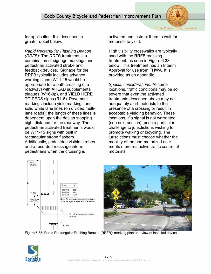
for application. It is described in greater detail below. Rapid Rectangular Flashing Beacon (RRFB): The RRFB treatment is a combination of signage markings and pedestrian activated strobe and feedback devices. Signage for the RRFB typically includes advance warning signs (W11-15 would be appropriate for a path crossing of a roadway) with AHEAD supplemental plaques (W16-9p), and YIELD HERE TO PEDS signs (R1-5). Pavement markings include yield markings and solid white lane lines (on divided multi-lane roads); the length of these lines is dependent upon the design stopping sight distance for the roadway. The pedestrian activated treatments would be W11-15 signs with built in rectangular strobe flashers. Additionally, pedestrian visible strobes and a recorded message inform pedestrians when the crossing is
activated and instruct them to wait for motorists to yield. High visibility crosswalks are typically used with the RRFB crossing treatment, as seen in Figure 6.33 below. This treatment has an Interim Approval for use from FHWA. It is provided as an appendix. Special considerations: At some locations, traffic conditions may be so severe that even the activated treatments described above may not adequately alert motorists to the presence of a crossing or result in acceptable yielding behavior. These locations, if a signal is not warranted (see next section), pose a particular challenge to jurisdictions wishing to promote walking or bicycling. The jurisdictions must choose whether the mobility of the non-motorized user merits more restrictive traffic control of motorists.
Figure 6.33: Rapid Rectangular Flashing Beacon (RRFB): marking plan and view of installed device
6-53 T:\08\8183-08 Cobb County Bike_Ped Improvement Plan\task 4\FINALfeb10\Ch 6 Doc.doc
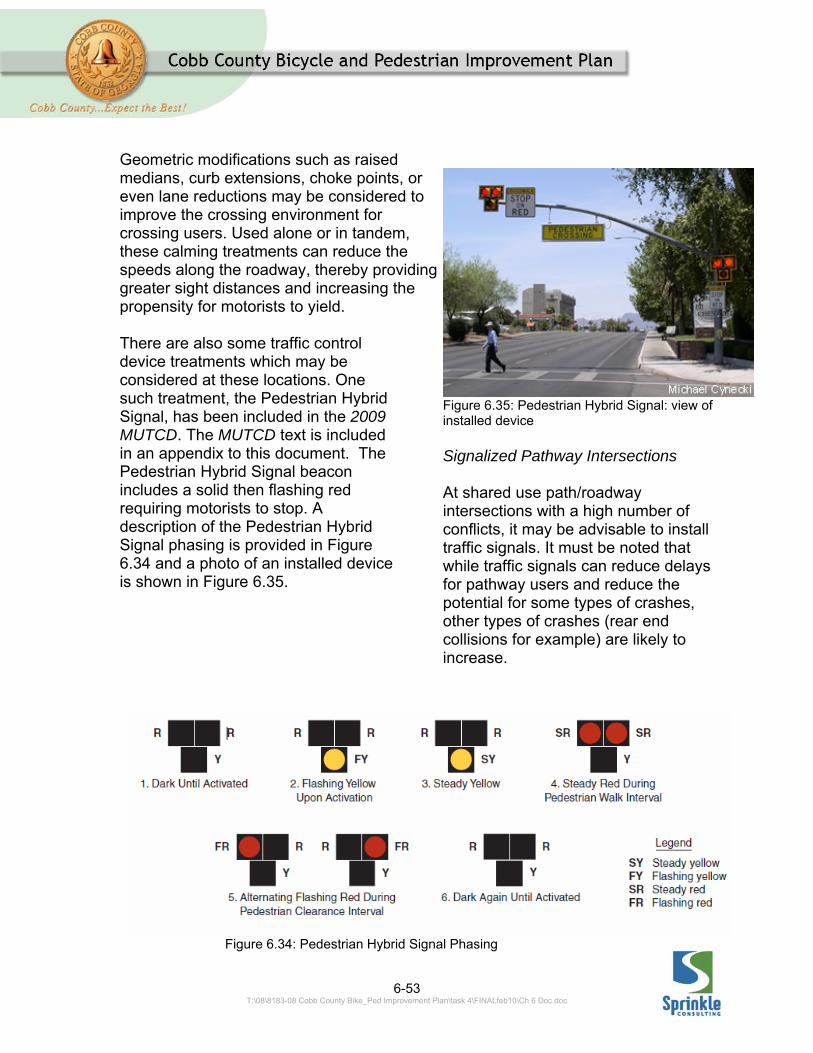
Geometric modifications such as raised medians, curb extensions, choke points, or even lane reductions may be considered to improve the crossing environment for crossing users. Used alone or in tandem, these calming treatments can reduce the speeds along the roadway, thereby providing greater sight distances and increasing the propensity for motorists to yield. There are also some traffic control device treatments which may be considered at these locations. One such treatment, the Pedestrian Hybrid Signal, has been included in the 2009 MUTCD. The MUTCD text is included in an appendix to this document. The Pedestrian Hybrid Signal beacon includes a solid then flashing red requiring motorists to stop. A description of the Pedestrian Hybrid Signal phasing is provided in Figure 6.34 and a photo of an installed device is shown in Figure 6.35.
Figure 6.35: Pedestrian Hybrid Signal: view of installed device Signalized Pathway Intersections At shared use path/roadway intersections with a high number of conflicts, it may be advisable to install traffic signals. It must be noted that while traffic signals can reduce delays for pathway users and reduce the potential for some types of crashes, other types of crashes (rear end collisions for example) are likely to increase.
Figure 6.34: Pedestrian Hybrid Signal Phasing

6-54 T:\08\8183-08 Cobb County Bike_Ped Improvement Plan\task 4\FINALfeb10\Ch 6 Doc.doc
Consequently, a traffic engineering study should be performed prior to the installation of any traffic signal. One of the basic methods for determining if a traffic signal may be considered at an intersection is a signal warrant study. The MUTCD provides eight different warrants for analyzing intersections:
Warrant 1, Eight-Hour Vehicular Volume Warrant 2, Four-Hour Vehicular Volume Warrant 3, Peak Hour Vehicular Volume Warrant 4, Pedestrian Volume Warrant 5, School Crossing Warrant 6, Coordinated Signal System Warrant 7, Crash Experience Warrant 8, Roadway Network
For shared use paths, any of these warrants may be applied. For the Pedestrian Volume and School Crossing warrants, both bicyclists and pedestrians may be counted to obtain crossing volumes. For the vehicular volume based warrants (1-3) only bicyclists may be counted.28
The Pedestrian Volume warrant has been revised in the 2009 MUTCD, the revised warrant is provided in an appendix of this document.
28 MUTCD, FHWA, 2009, pg. 9D-1.
6.4 BIKE ROUTES Bike routes can be defined as the links between origins and destinations that have been improved for, or are for some reason considered preferable for, bicycle travel. Bike route wayfinding signage should provide the following basic information:
Destination of the route Distance to the route’s
destination Direction of the route
Bike routes can be divided into the two following categories: General Routes and Number Routes. General Routes are links with a single origin and a single destination. Number Routes form a network of Bike routes that connect several origins to several destinations. 6.4.1 GENERAL ROUTES
General Routes connect users to a single destination. Typical single destinations include:
Attraction Areas (i.e. stadiums,
parks, etc.) Neighborhood Areas (i.e.
downtown, historic neighborhoods, etc.)
Trail Networks (i.e. Silver Comet Trail)
6-55 T:\08\8183-08 Cobb County Bike_Ped Improvement Plan\task 4\FINALfeb10\Ch 6 Doc.doc
A typical sign that conveys the basic wayfinding information for General Routes is shown below in Figure 6.36.
Figure 6.36: Typical General Route Signage
6.4.2 NUMBER ROUTES
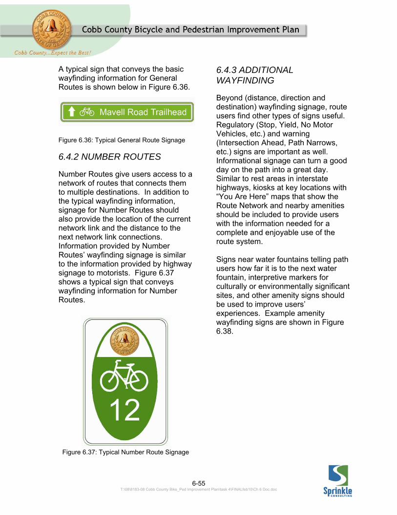
Number Routes give users access to a network of routes that connects them to multiple destinations. In addition to the typical wayfinding information, signage for Number Routes should also provide the location of the current network link and the distance to the next network link connections. Information provided by Number Routes’ wayfinding signage is similar to the information provided by highway signage to motorists. Figure 6.37 shows a typical sign that conveys wayfinding information for Number Routes.
Figure 6.37: Typical Number Route Signage
6.4.3 ADDITIONAL WAYFINDING
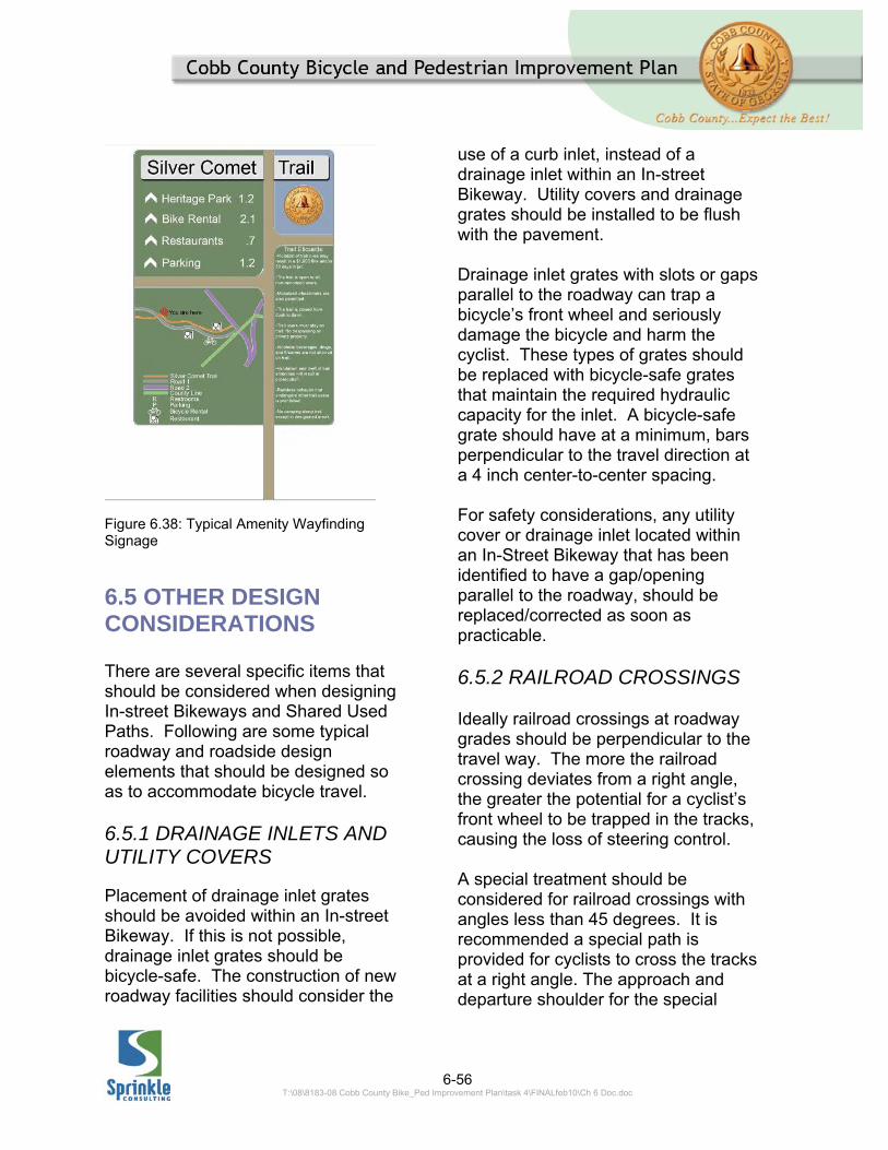
Beyond (distance, direction and destination) wayfinding signage, route users find other types of signs useful. Regulatory (Stop, Yield, No Motor Vehicles, etc.) and warning (Intersection Ahead, Path Narrows, etc.) signs are important as well. Informational signage can turn a good day on the path into a great day. Similar to rest areas in interstate highways, kiosks at key locations with “You Are Here” maps that show the Route Network and nearby amenities should be included to provide users with the information needed for a complete and enjoyable use of the route system. Signs near water fountains telling path users how far it is to the next water fountain, interpretive markers for culturally or environmentally significant sites, and other amenity signs should be used to improve users’ experiences. Example amenity wayfinding signs are shown in Figure 6.38.
6-56 T:\08\8183-08 Cobb County Bike_Ped Improvement Plan\task 4\FINALfeb10\Ch 6 Doc.doc
Figure 6.38: Typical Amenity Wayfinding Signage
6.5 OTHER DESIGN CONSIDERATIONS There are several specific items that should be considered when designing In-street Bikeways and Shared Used Paths. Following are some typical roadway and roadside design elements that should be designed so as to accommodate bicycle travel. 6.5.1 DRAINAGE INLETS AND UTILITY COVERS
Placement of drainage inlet grates should be avoided within an In-street Bikeway. If this is not possible, drainage inlet grates should be bicycle-safe. The construction of new roadway facilities should consider the
use of a curb inlet, instead of a drainage inlet within an In-street Bikeway. Utility covers and drainage grates should be installed to be flush with the pavement. Drainage inlet grates with slots or gaps parallel to the roadway can trap a bicycle’s front wheel and seriously damage the bicycle and harm the cyclist. These types of grates should be replaced with bicycle-safe grates that maintain the required hydraulic capacity for the inlet. A bicycle-safe grate should have at a minimum, bars perpendicular to the travel direction at a 4 inch center-to-center spacing. For safety considerations, any utility cover or drainage inlet located within an In-Street Bikeway that has been identified to have a gap/opening parallel to the roadway, should be replaced/corrected as soon as practicable. 6.5.2 RAILROAD CROSSINGS Ideally railroad crossings at roadway grades should be perpendicular to the travel way. The more the railroad crossing deviates from a right angle, the greater the potential for a cyclist’s front wheel to be trapped in the tracks, causing the loss of steering control. A special treatment should be considered for railroad crossings with angles less than 45 degrees. It is recommended a special path is provided for cyclists to cross the tracks at a right angle. The approach and departure shoulder for the special
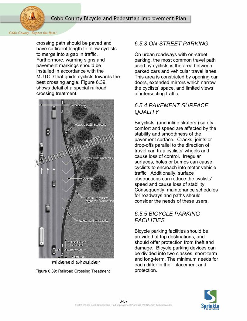
6-57 T:\08\8183-08 Cobb County Bike_Ped Improvement Plan\task 4\FINALfeb10\Ch 6 Doc.doc
crossing path should be paved and have sufficient length to allow cyclists to merge into a gap in traffic. Furthermore, warning signs and pavement markings should be installed in accordance with the MUTCD that guide cyclists towards the best crossing angle. Figure 6.39 shows detail of a special railroad crossing treatment.
6.5.3 ON-STREET PARKING
On urban roadways with on-street parking, the most common travel path used by cyclists is the area between parked cars and vehicular travel lanes. This area is constricted by opening car doors, extended mirrors which narrow the cyclists’ space, and limited views of intersecting traffic. 6.5.4 PAVEMENT SURFACE QUALITY
Bicyclists’ (and inline skaters’) safety, comfort and speed are affected by the stability and smoothness of the pavement surface. Cracks, joints or drop-offs parallel to the direction of travel can trap cyclists’ wheels and cause loss of control. Irregular surfaces, holes or bumps can cause cyclists to encroach into motor vehicle traffic. Additionally, surface obstructions can reduce the cyclists’ speed and cause loss of stability. Consequently, maintenance schedules for roadways and paths should consider the needs of these users. 6.5.5 BICYCLE PARKING FACILITIES
Bicycle parking facilities should be provided at trip destinations, and should offer protection from theft and damage. Bicycle parking devices can be divided into two classes, short-term and long-term. The minimum needs for each differ in their placement and protection.
Figure 6.39: Railroad Crossing Treatment
6-58 T:\08\8183-08 Cobb County Bike_Ped Improvement Plan\task 4\FINALfeb10\Ch 6 Doc.doc
Long-term parking facilities should provide a high degree of security and protection from the weather. Apartment complexes, schools, employment centers, and transit stops are typical places where long-term parking facilities are needed. These facilities are usually lockers, cages or rooms inside buildings. Short-term facilities should be provided in decentralized parking areas, where the bicycle is left for a short period of time and is visible and convenient to the building entrances. Retail centers, restaurants, and parks are typical places where short-term parking facilities are needed. Both short-term and long-term parking facilities should be capable of accommodating various types of bicycles, and should be easy to operate. If possible, signs depicting how to operate the facility should be posted. 6.5.6 BICYCLE AMENITIES
Providing supplemental improvements should be considered to enhance and/or promote the use of bikeways. For long continuous paths, rest areas with water fountains are desirable. Improvements that promote a smooth interconnection between bikeways and other transit facilities should also be considered. For example, consider adding racks to buses, connecting bikeways with “park-n-ride” mass-transit facilities or allowing bicycles in rapid rails.
Informational maps showing bike route networks, and their connection to other transit facilities, are economical and highly successful ways to improve the public’s awareness of bicycle facilities. Furthermore, maps can help deter cyclists from using high-speed/volume roadways and other facilities identified as less favorable for bikeways.
6.6 PEDESTRIAN FACILITIES The planning, design and operation of pedestrian facilities share a main goal: the safety of pedestrians. Special attention to pedestrian safety is needed, because pedestrians are the most vulnerable of all transportation facility users. Pedestrian facilities should also accommodate pedestrians of all abilities. For this reason accessibility is another key factor in the planning, design and operation of pedestrian facilities. 6.6.1 SIDEWALK DESIGN
Routes intended for pedestrian use should include a walkway that meets ADA requirements. Construction of new pedestrian facilities or improvement of existing facilities should meet ADA requirements. Various types of walkways can be used to accommodate pedestrians in the public right-of-way. The most common type is a sidewalk parallel to the roadway. Off-road paths could also be used in rural areas and shared used paths can be used to
6-59 T:\08\8183-08 Cobb County Bike_Ped Improvement Plan\task 4\FINALfeb10\Ch 6 Doc.doc
accommodate cyclists and pedestrians. Sidewalk widths The minimum clear width for a sidewalk should be 4 feet, not including attached curbs. Where sidewalks are less than 5 feet in width, passing spaces at least 5 feet in width, are required (by ADA) to be provided at reasonable intervals not to exceed 200 feet. The 5feet width is needed for wheelchair users to pass another or turn around. Along areas with high pedestrian traffic (i.e. central business district) sidewalk widths greater than 5feet should be included. For example, on sidewalks adjacent to store fronts an additional 2 feet should be provided to accommodate shy distance from walls, shoppers stopping to look into windows, and to avoid conflicts with opening doors and pedestrian traffic. There are planning tools which can help designers select appropriate sidewalk widths. First, the capacity based sidewalk Level of Service from the current Highway Capacity Manual. This methodology provides a way to determine sidewalk widths based upon acceptable levels of congestion on the sidewalk. A second method, which will be included in the 2010 update to the Highway Capacity Manual is the same Pedestrian Level of Service used by Cobb County for the Bicycle and Pedestrian Improvement Plan. This method ties sidewalk widths to pedestrians’ perceptions of safety and comfort.
Buffer widths To improve pedestrian safety, buffers should be considered along collector and arterial roadways. Buffer area plantings and amenities aid in creating an inviting social setting for the pedestrians. On-street parking and bike lanes can also act as a sidewalk buffer. Buffer widths are measured from the edge of the traveled way. In areas without on-street parking or bike lanes a planting strip is recommended. Local and collector streets should have planting strips from 2 to 4 feet in width. Arterial and major streets should include planting strips from 5 to 6feet in width. Where planting strips are not provided the desirable width for a curb-attached sidewalk should be 6 feet on residential streets and 8 feet on commercial streets. Bus stops separated from sidewalks by a landscape buffer area should include 60” x 80” paved areas for the loading unloading busses. The bus stop connections also need to meet the requirements of the ADA. Grade and cross slope Maximum cross-slope permitted by ADA requirements is 2 percent on any accessible route. When sidewalks are adjacent to a roadway the longitudinal grades are not limited as long as the sidewalk follows the adjacent street’s grade. If the sidewalk does not follow the street’s grade, the maximum grade allowed by ADA requirements is 5 percent and up to an 8.3 percent ramp
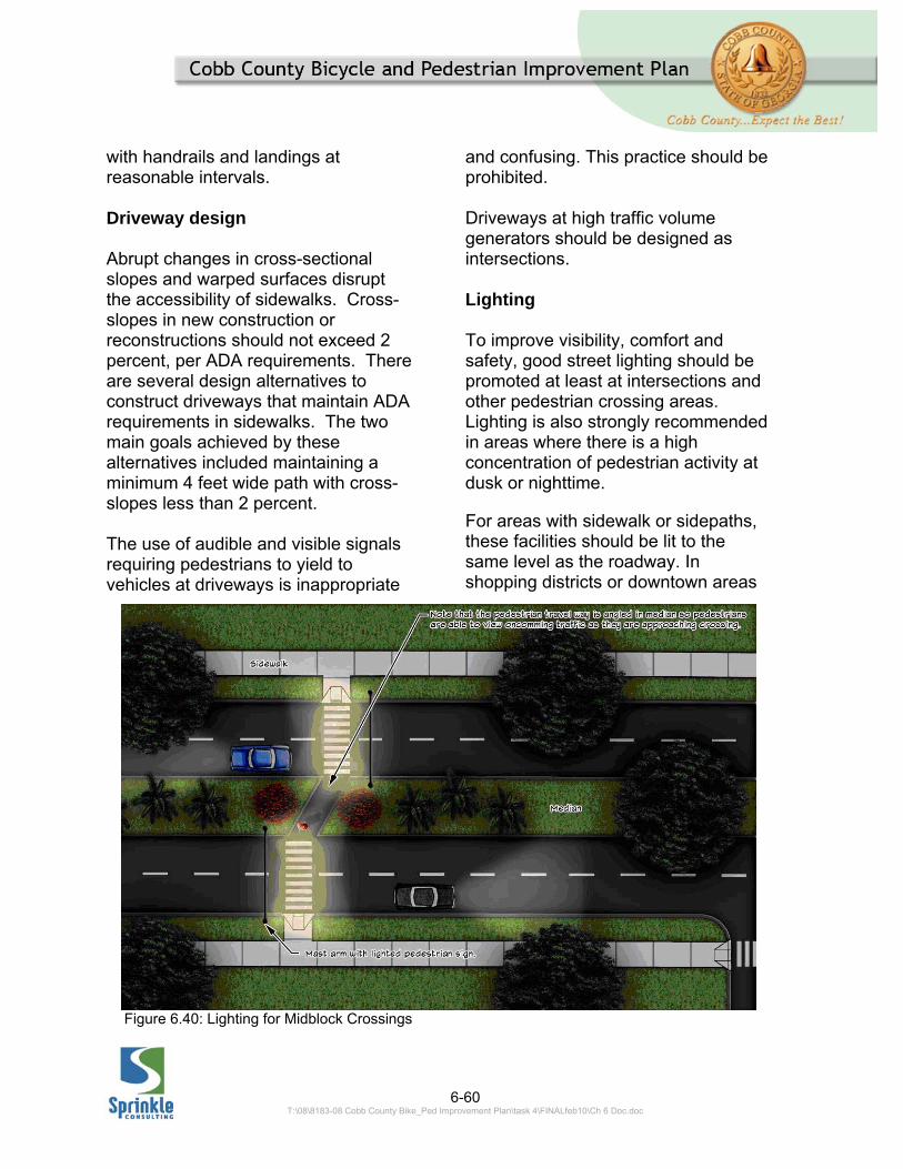
6-60 T:\08\8183-08 Cobb County Bike_Ped Improvement Plan\task 4\FINALfeb10\Ch 6 Doc.doc
Figure 6.40: Lighting for Midblock Crossings
with handrails and landings at reasonable intervals. Driveway design Abrupt changes in cross-sectional slopes and warped surfaces disrupt the accessibility of sidewalks. Cross-slopes in new construction or reconstructions should not exceed 2 percent, per ADA requirements. There are several design alternatives to construct driveways that maintain ADA requirements in sidewalks. The two main goals achieved by these alternatives included maintaining a minimum 4 feet wide path with cross-slopes less than 2 percent. The use of audible and visible signals requiring pedestrians to yield to vehicles at driveways is inappropriate
and confusing. This practice should be prohibited. Driveways at high traffic volume generators should be designed as intersections. Lighting To improve visibility, comfort and safety, good street lighting should be promoted at least at intersections and other pedestrian crossing areas. Lighting is also strongly recommended in areas where there is a high concentration of pedestrian activity at dusk or nighttime.
For areas with sidewalk or sidepaths, these facilities should be lit to the same level as the roadway. In shopping districts or downtown areas
6-61 T:\08\8183-08 Cobb County Bike_Ped Improvement Plan\task 4\FINALfeb10\Ch 6 Doc.doc
landscaping, awning, or signs may create dark spots along the pedestrian route. In these locations it is desirable to include pedestrian level lighting in addition to street lighting, to improve the security and comfort of pedestrians. At midblock crossings pedestrians should be front-lit, not back-lit. See Figure 6.40 on the previous page. Protruding Objects and Obstacles
Just like motorists and cyclists, pedestrians have a clearance envelope that should be maintained to prevent conflicts and promote safety. At a minimum an envelope 7 feet in height and 4 feet in width should be kept free of obstacles. However, on wider urban sidewalks the 4-foot wide path cannot be clearly defined. For this reason the following guidelines should be followed to prevent the intrusion of objects and obstacles within the pedestrian clearance envelope.
Wall mounted objects: Objects should not protrude more than 4 inches from a wall when located between 27 inches and 7 feet above the sidewalk. Single-post mounted objects: Objects should not overhang more than 4 inches per side of post when located between 27 inches and 80 inches above the sidewalk. Multiple-Post Mounted Objects: The lowest edge of an object mounted on multiple posts having a clear distance
between adjacent posts greater than 1feet shall be no higher than 27 inches or no lower than 7feet above the sidewalk. Drainage grates and utility covers: Manhole covers, hatches and other utility grates, if possible, should be placed outside the pedestrian travel way. However, when present in the walking surface, grates and covers should be mounted flush with the surface. To prevent trapping canes or wheelchairs grate openings should not exceed 5 inches in the direction of travel. If grates in the walking surface have elongated openings, they must be placed so that the long dimension is perpendicular to the predominant direction of travel. Street trees and buffer plantings: Care should be taken to avoid planting trees or large shrubs that will obstruct the visibility (at planting and maturity height) of pedestrians attempting to cross the street or motorists attempting to enter a driveway. Trees with large canopies planted between the sidewalk and street should generally be trimmed in a manner that provides at least 7feet of clearance between the branches and sidewalk. Tree wells and grates should follow the same criteria described for drainage grates and utility covers described above. 6.6.2 PEDESTRIAN ROADWAY CROSSING DESIGN
Roadways may have excellent sidewalk facilities, but if the street

6-62 T:\08\8183-08 Cobb County Bike_Ped Improvement Plan\task 4\FINALfeb10\Ch 6 Doc.doc
crossing treatments are uncomfortable to use few pedestrians will use the sidewalks. Following are some typical guidelines and treatments that can be used at pedestrian crossings to enhance safety and functionality. Intersection/roadway design Intersections are the most practical and common crossings for pedestrians. Consequently, where pedestrians are anticipated, they should be considered a design user of the intersection. Fortunately, the AASHTO Greenbook guidance on intersection design provides for intersections that work for all users.29 Specifically, it states intersections should be designed to:
provide for conflicts at right angles;
provide for one decision/conflict at a time;
provide protection for pedestrians;
channelize intersections; and minimize conflict areas.
Turning radii Intersection corner radii should be designed based upon a design vehicle. The type of design vehicle considered is dependent upon the types of roadways intersecting. Turning radius templates should be
29 A Policy on the Geometric Design of Highways and Streets, Chapter 9, 2004, AASHTO.
used during design to ensure that adequate, but not excessive, space is provided for the appropriate design vehicle. Local streets: Passenger vehicles can be accommodated with 10- to 15-foot street corner radii. Utility vehicles can encroach into adjacent lanes of traffic to make turns if the conflicting approaches are required to stop. In these, typically local street/local street intersections, these small curb radii may be acceptable. This is particularly true when on street parking is allowed on the roadway and provides additional “effective radii” for turning motor vehicles. Twenty-five-foot radii may be more appropriate for new construction depending on the roadway receiving width and design vehicle. Collector streets: On collector roadway intersections, more frequent turning truck traffic should be anticipated. Thirty-foot radii should be provided so that an occasional truck can turn without too much encroachment. Arterial streets: On arterial roadways where truck traffic is likely, designing with turning templates or truck turning simulation software is very important. This allows for the turning vehicles to be accommodated while minimizing conflict areas. To accommodate turning buses, or large truck combinations, 40-foot radii, or preferably three centered curves, should be provided. Alternatively, right turn channelization islands can

6-63 T:\08\8183-08 Cobb County Bike_Ped Improvement Plan\task 4\FINALfeb10\Ch 6 Doc.doc
facilitate turning trucks while minimizing crossing distances for pedestrians. Again, where stop control is provided for conflicting vehicles, intersections may be designed to allow trucks to use the entire receiving width of an intersection. Figure 6.41 shows the same intersection with two different design concepts. Both accommodate a large tractor trailer truck (WB -67 design vehicle). However, the design on the right provides increased storage for turning vehicles. It also allows vehicles to clear the intersection more quickly, thus reducing required yellow-plus-all-red signal phase time at the intersection and increasing capacity. If mast arm signals are used, placing the poles within the channelization island (the northeast corner may be a bit small for this) can dramatically reduce construction costs.
For pedestrians this design dramatically reduces the pedestrian crossing distances (and therefore the clearance intervals – another benefit for motorists). With curb modifications it could also reduce the speed of right turning motor vehicles. It allows the pedestrians to negotiate the right turn separately from the rest of the intersections; pedestrians have been found to prefer these multi-step crossing approach at large intersections.) 30 Pedestrian Treatments Curb ramps should follow ADA to provide an accessible route for all types of pedestrian users.
30 Petritsch, Landis, Huang, McLeod, Challa, Guttenplan. “Level-of-Service Model for Pedestrians at Signalized Intersections”, TRR 1939, TRB 2005.
Figure 6.41: Intersection examples
6-64 T:\08\8183-08 Cobb County Bike_Ped Improvement Plan\task 4\FINALfeb10\Ch 6 Doc.doc
Intersections with on-street parking need special attention with regard to pedestrian and motorist sight visibility. Parked cars can hinder visibility between pedestrians and motorists. For example, a parked car 20 feet away from the crosswalk can visually screen children or people in wheelchairs from oncoming motorist traffic. If the parked vehicle is a van or a sport utility vehicle, no pedestrians may be visible to the approaching motorists. For this reason curb extensions should be used as an intersection treatment to increase sight distance. In general, curb extensions should extend the width of the on-street parking lane, approximately 6feet from the curb. If a curb extension would interfere with a bike lane, a further setback from the crosswalk for the on-street parked car should be required. Existing raised medians 6 feet or more in width can be used as crossing islands to provide a storage area for pedestrians in long intersections. New intersections, where crossing distances exceed 60 feet should include a crossing island at least 6feet in width. The 6-foot width provides space for one wheelchair user or more than one pedestrian to wait. The cut-through area in crossing medians can be angled to increase the pedestrians’ visibility of incoming traffic; this is particularly useful in mid-block crossings. In constrained conditions, travel lanes can be narrowed to 10 feet to provide space for a crossing island. Two-foot detectable warnings strips should be placed on both sides
of median refuge islands six or more feet in width. The width of marked crosswalks should not be less than 6 feet. Stop and Yield line setbacks should be used with marked crosswalks. When used at controlled intersections, stop lines should be placed approximately 10 feet and no less than 4 feet in advance and in a parallel direction to the crosswalk. At uncontrolled intersections on multilane roads setbacks of 20 to 50 feet are desirable for yield lines to provide improved visibility of and for motorists approaching in any lane. Midblock crossings The previous section on traffic control for shared use path crossings of roadways is also applicable to midblock pedestrian crossings. At midblock pedestrian crossings, however, all signs should be pedestrian oriented (the PEDESTRIAN
CROSSING sign should be used instead of the COMBINED BICYCLE/PEDESTRIAN
CROSSING sign). Pedestrian signals When installed correctly, traffic signals benefit pedestrians by interrupting heavy volumes of motor vehicles where there are insufficient gaps to cross safely at intersections or midblock crossings (see the Shared Use Path discussion above for warrant information). Traffic signals are required to take into consideration the
6-65 T:\08\8183-08 Cobb County Bike_Ped Improvement Plan\task 4\FINALfeb10\Ch 6 Doc.doc
needs of pedestrian traffic.31 Pedestrian signal heads are recommended at all signals were pedestrian treatments are provided along the approach roadways or corners. According the MUTCD pedestrian signal heads must be installed –
A. If a traffic control signal is justified by an engineering study and meets either Warrant 4, Pedestrian Volume or Warrant 5, School Crossing (see Chapter 4C); B. If an exclusive signal phase is provided or made available for pedestrian movements in one or more directions, with all conflicting vehicular movements being stopped; or C. At an established school crossing at any signalized location. D. Where engineering judgment determines that multiphase signal indications (as with split-phase timing) would tend to confuse or cause conflicts with pedestrians using a crosswalk guided only by vehicular signal indications.32
The MUTCD recommends that traffic signal timing for pedestrians be based on an assumed speed of 4ft/sec. However, this speed should vary based on the individual characteristics of pedestrians. For example, a design crossing speed of 3ft/sec should be used at intersections where older pedestrians are expected.
31 MUTCD, FHWA, 2009, P 450. 32 MUTCD, FHWA, 2009, P 495.
Pedestrian signal heads provide signal directions exclusively intended for pedestrian traffic. These indications consist of a Walking Person (symbolizing Walk) and an Upraised Hand (symbolizing Do not Walk). The 2009 MUTCD requires countdown displays be provided for all but the shortest of pedestrian crossings.33 Pedestrian clearance intervals should be calculated upon an assumed walking speed of 3.5 feet per second. A walking speed of up to 4 feet per second may be used to if some technique such as extended push button press or passive pedestrian detection is being used to provide an option for the longer clearance interval when needed. Accessible Pedestrian Signals When crossing a street at a signalized location, pedestrians who have visual disabilities initiate their crossing when they hear the traffic in front of them stop and the traffic alongside them begin to move; this usually corresponds with the onset of the green interval. In an increasing number of locations – at complex intersections, or intersections with unusual signal timing plans - the intersection environment does not
33 The 2009 MUTCD has no compliance date. All traffic control devices that are currently in place may remain in place for the duration of their useful lives. However, all new traffic control devices are to be compliant with the 2009 MUTCD. The state of Georgia has until January 2012 to adopt the 2009 MUTCD.
6-66 T:\08\8183-08 Cobb County Bike_Ped Improvement Plan\task 4\FINALfeb10\Ch 6 Doc.doc
provide the information pedestrians with visual disabilities need to make an accurate judgment on when it is safe to cross the street. Accessible Pedestrian Signals (APS) are devices that provide audible and tactile information for pedestrians with vision and/or hearing impairments. APS treatments include a locator tone that assists pedestrians with visual disabilities in finding the pedestrian push button. The push button is large, 2-inch diameter minimum, and is easy to press. An arrow raised in relief is located on the pedestrian push button to direct the pedestrian toward the crossing. Some APS devices have raised intersection “maps” to let pedestrians know how many lanes they will be crossing and the lane configurations. The MUTCD provides guidance on where APS signals should be installed. At a minimum, if a request for an APS is received by Cobb County; the request should be forwarded to an Orientation and Mobility Specialist in the Georgia Department of Labor - Rehabilitation Services, for an assessment. If this agency decides an APS should be installed, then the County should install the treatments. Complete requirements for APS can be found in Section 4E.06 of the MUTCD.

6-67 T:\08\8183-08 Cobb County Bike_Ped Improvement Plan\task 4\FINALfeb10\Ch 6 Doc.doc
APPENDIX 6.A RAPID RECTANGULAR FLASHING BEACON
FHWA INTERIM APPROVAL
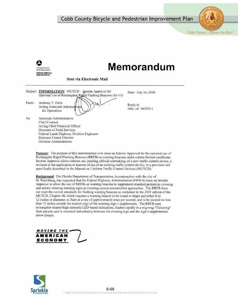
6-68 T:\08\8183-08 Cobb County Bike_Ped Improvement Plan\task 4\FINALfeb10\Ch 6 Doc.doc
6-69 T:\08\8183-08 Cobb County Bike_Ped Improvement Plan\task 4\FINALfeb10\Ch 6 Doc.doc

6-70 T:\08\8183-08 Cobb County Bike_Ped Improvement Plan\task 4\FINALfeb10\Ch 6 Doc.doc
6-71 T:\08\8183-08 Cobb County Bike_Ped Improvement Plan\task 4\FINALfeb10\Ch 6 Doc.doc
6-72 T:\08\8183-08 Cobb County Bike_Ped Improvement Plan\task 4\FINALfeb10\Ch 6 Doc.doc

6-73 T:\08\8183-08 Cobb County Bike_Ped Improvement Plan\task 4\FINALfeb10\Ch 6 Doc.doc

6-74 T:\08\8183-08 Cobb County Bike_Ped Improvement Plan\task 4\FINALfeb10\Ch 6 Doc.doc

6-75 T:\08\8183-08 Cobb County Bike_Ped Improvement Plan\task 4\FINALfeb10\Ch 6 Doc.doc
APPENDIX 6.B PEDESTRIAN HYBRID SIGNALS 2009 MANUAL OF UNIFORM TRAFFIC CONTROL DEVICES

6-76 T:\08\8183-08 Cobb County Bike_Ped Improvement Plan\task 4\FINALfeb10\Ch 6 Doc.doc
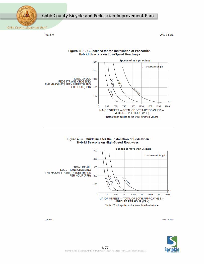
6-77 T:\08\8183-08 Cobb County Bike_Ped Improvement Plan\task 4\FINALfeb10\Ch 6 Doc.doc

6-78 T:\08\8183-08 Cobb County Bike_Ped Improvement Plan\task 4\FINALfeb10\Ch 6 Doc.doc
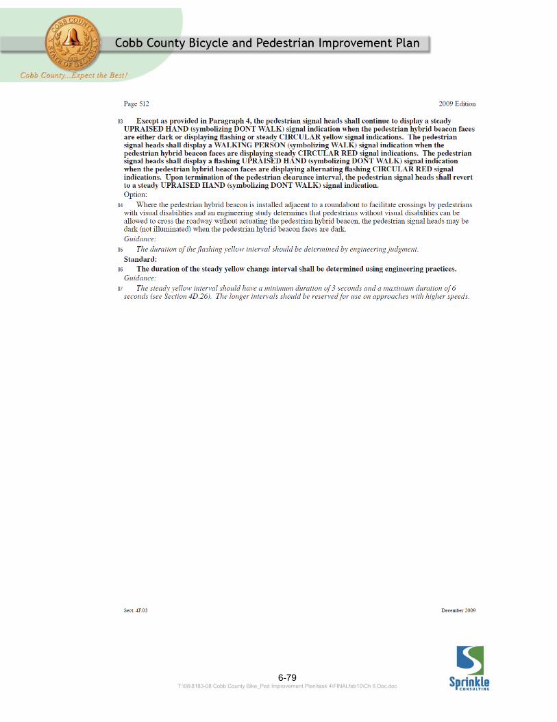
6-79 T:\08\8183-08 Cobb County Bike_Ped Improvement Plan\task 4\FINALfeb10\Ch 6 Doc.doc

6-80 T:\08\8183-08 Cobb County Bike_Ped Improvement Plan\task 4\FINALfeb10\Ch 6 Doc.doc
6-81 T:\08\8183-08 Cobb County Bike_Ped Improvement Plan\task 4\FINALfeb10\Ch 6 Doc.doc
APPENDIX 6.C PEDESTRIAN SIGNAL WARRANTS 2009 MANUAL OF UNIFORM TRAFFIC CONTROL DEVICES
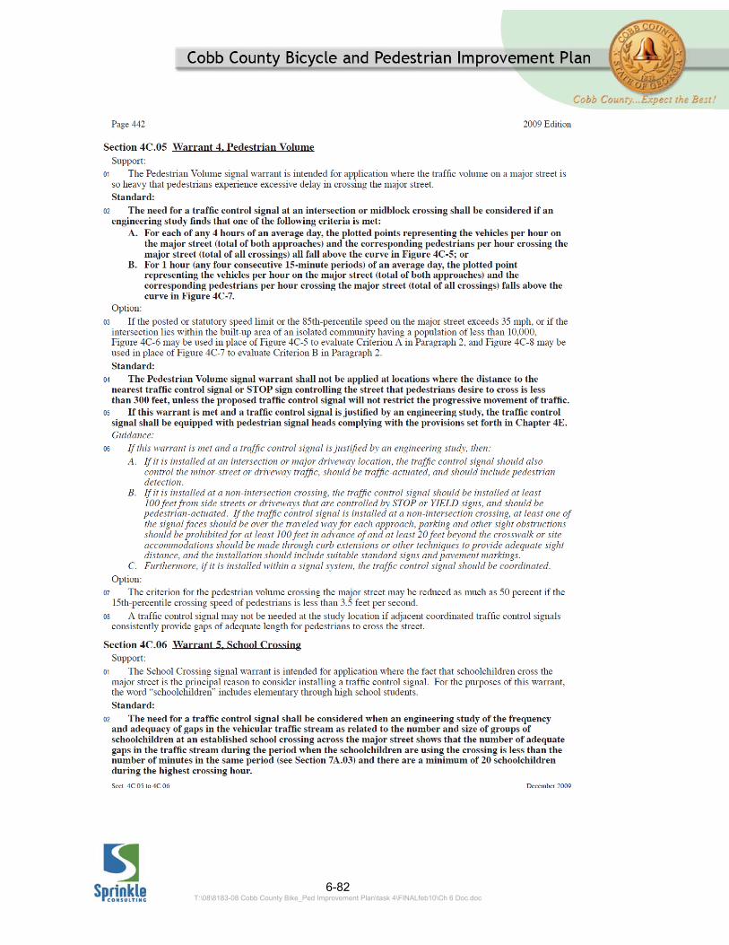
6-82 T:\08\8183-08 Cobb County Bike_Ped Improvement Plan\task 4\FINALfeb10\Ch 6 Doc.doc

6-83 T:\08\8183-08 Cobb County Bike_Ped Improvement Plan\task 4\FINALfeb10\Ch 6 Doc.doc
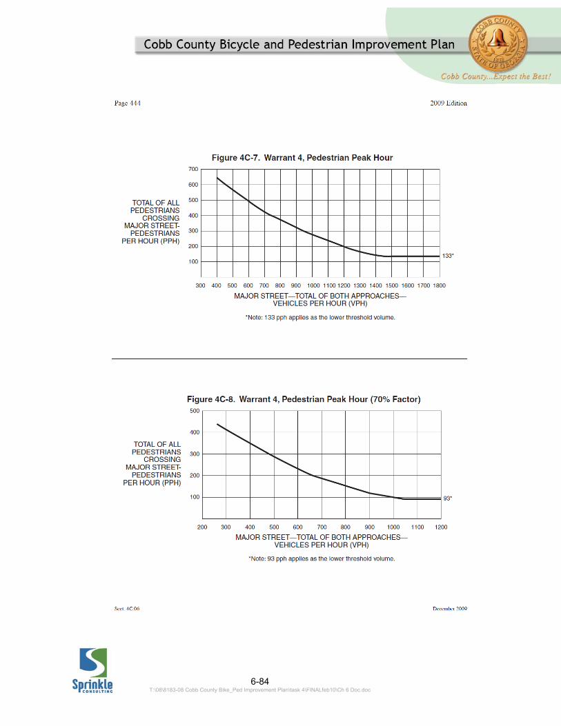
6-84 T:\08\8183-08 Cobb County Bike_Ped Improvement Plan\task 4\FINALfeb10\Ch 6 Doc.doc
6-85 T:\08\8183-08 Cobb County Bike_Ped Improvement Plan\task 4\FINALfeb10\Ch 6 Doc.doc