Embed Size (px)
Citation preview
Chap-1 (MM Comm)
Chapter 6
Digital Communications Basics6.1 Introduction6.2 Transmission media6.3 Source of signal impairment6.4 Asynchronous Transmission6.5 Synchronous Transmission6.6 Error Detection Methods6.7 Protocol basics6.8 The HDLC protocol
Chap-1 (MM Comm)
Transmission SIGNALs
• Physical layer– manage the moving information in the form of
electromagnetic across network connection• information
– voice, image, numeric data, characters, or video• collecting information from computer• sending information from computer• use encoder/decoder to create/reconstruct a stream of 1s and 0s
– converts a form to transfer via transmission media» the form of electromagnetic signals
Chap-1 (MM Comm)
Analog and Digital Signal
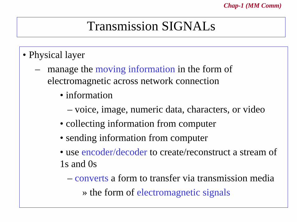
• Analog– refers to something that is continuous
• Digital– refers to something that is discrete
Text,Voice,VideoImage,
etc
Encoder
Information
Digital
Analog

Chap-1 (MM Comm)
6.1 Introduction• Baseband transmission : digital interface via NIC in LAN,ISDN

Chap-1 (MM Comm)
Modulated transmission• Modulated transmission : analog transmission in PSTN
Chap-1 (MM Comm)
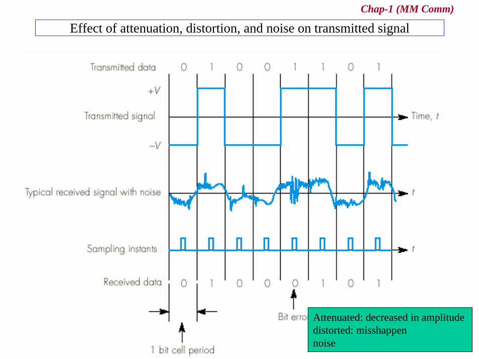
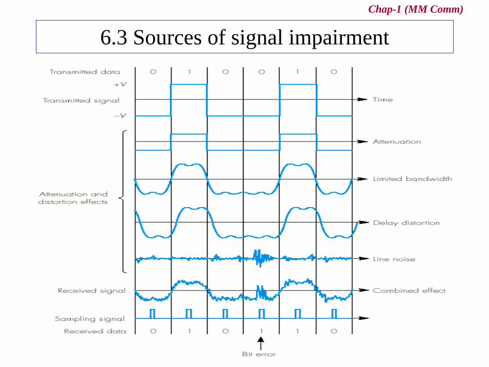
Effect of attenuation, distortion, and noise on transmitted signal
Attenuated: decreased in amplitudedistorted: misshappennoise

Chap-1 (MM Comm)
6.2 Transmission media (1)
(a) Two-wire and multiwire open line
(b) Unshielded twisted pair
Chap-1 (MM Comm)
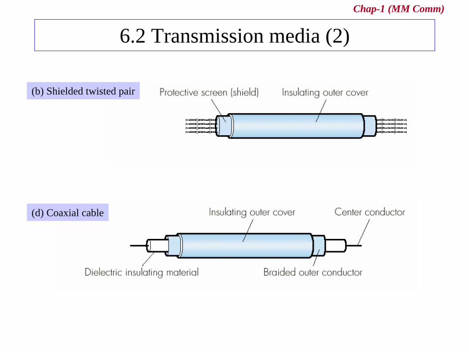
6.2 Transmission media (2)
(d) Coaxial cable
(b) Shielded twisted pair
Chap-1 (MM Comm)
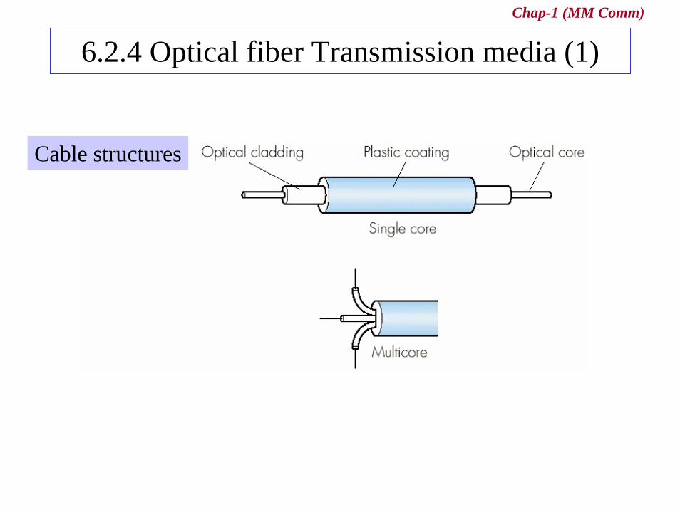
6.2.4 Optical fiber Transmission media (1)
Cable structures
Chap-1 (MM Comm)
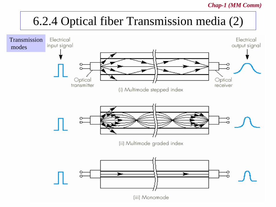
6.2.4 Optical fiber Transmission media (2)Transmissionmodes
Chap-1 (MM Comm)
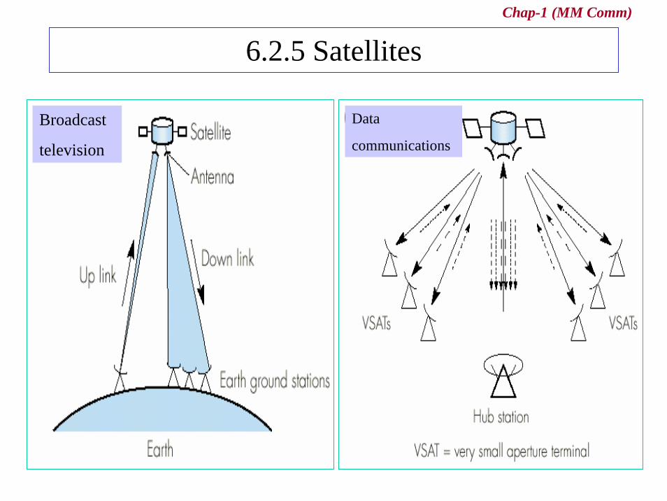
6.2.5 Satellites
Broadcast
television
Data
communications
Chap-1 (MM Comm)
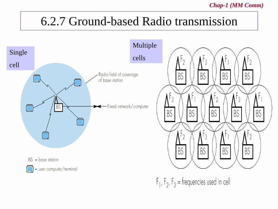
6.2.7 Ground-based Radio transmission
Single
cell
Multiple
cells
Chap-1 (MM Comm)
6.3 Sources of signal impairment
Chap-1 (MM Comm)
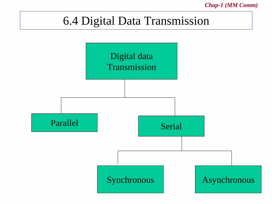
6.4 Digital Data Transmission
Digital dataTransmission
Parallel Serial
AsynchronousSynchronous
Chap-1 (MM Comm)
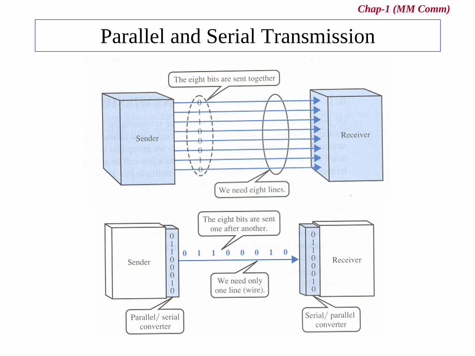
Parallel and Serial Transmission

Chap-1 (MM Comm)
Parallel and Serial Transmission (2)• All transfer that are external to the system
» are carried out bit-serially
• NIC must perform the following functions– parallel-to-serial conversion of each character– serial-to-parallel conversion of each received character– achieve bit, character, and frame synchronization in
receiver– generate a suitable error check digits
Chap-1 (MM Comm)
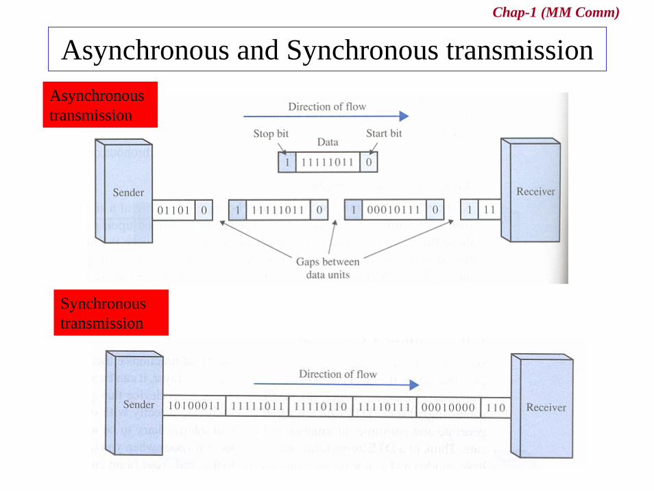
Asynchronous and Synchronous transmissionAsynchronous transmission
Synchronous transmission

Chap-1 (MM Comm)
Asynchronous transmission• Send one start bit (0) at beginning and one or more stop
bits (1s) at the end of each byte• may be a gap between each byte
– means “asynchronous at the byte level”– but the bits are still synchronized

Chap-1 (MM Comm)
Synchronous transmission
• Send bits one after another without start/stop bits or gaps• is the responsibility of the receiver to group the bits
Chap-1 (MM Comm)
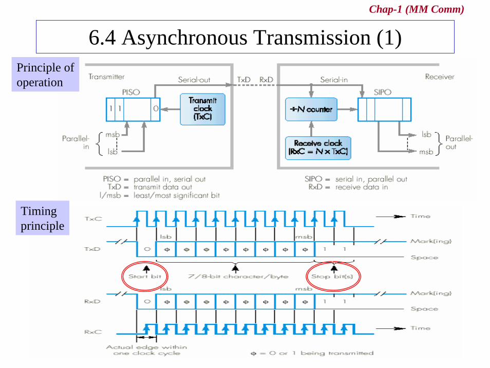
6.4 Asynchronous Transmission (1)Principle ofoperation
Timingprinciple
Chap-1 (MM Comm)
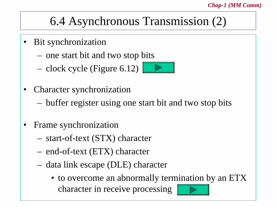
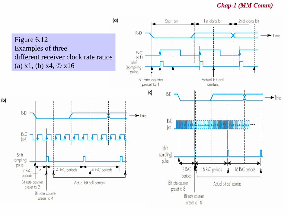
6.4 Asynchronous Transmission (2)• Bit synchronization
– one start bit and two stop bits– clock cycle (Figure 6.12)
• Character synchronization– buffer register using one start bit and two stop bits
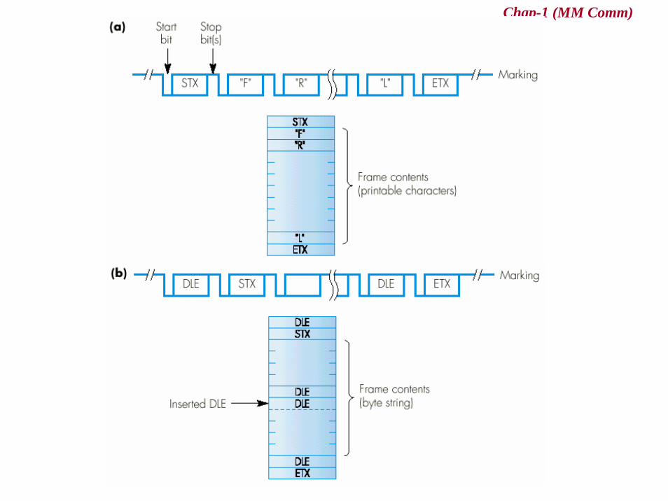
• Frame synchronization– start-of-text (STX) character– end-of-text (ETX) character– data link escape (DLE) character
• to overcome an abnormally termination by an ETX character in receive processing
Chap-1 (MM Comm)
Figure 6.12 Examples of three different receiver clock rate ratios(a) x1, (b) x4, © x16
Chap-1 (MM Comm)

Chap-1 (MM Comm)
6.5 Synchronous Transmission (1)• Two Synchronous Transmission
– Character-oriented– Bit-oriented
Chap-1 (MM Comm)
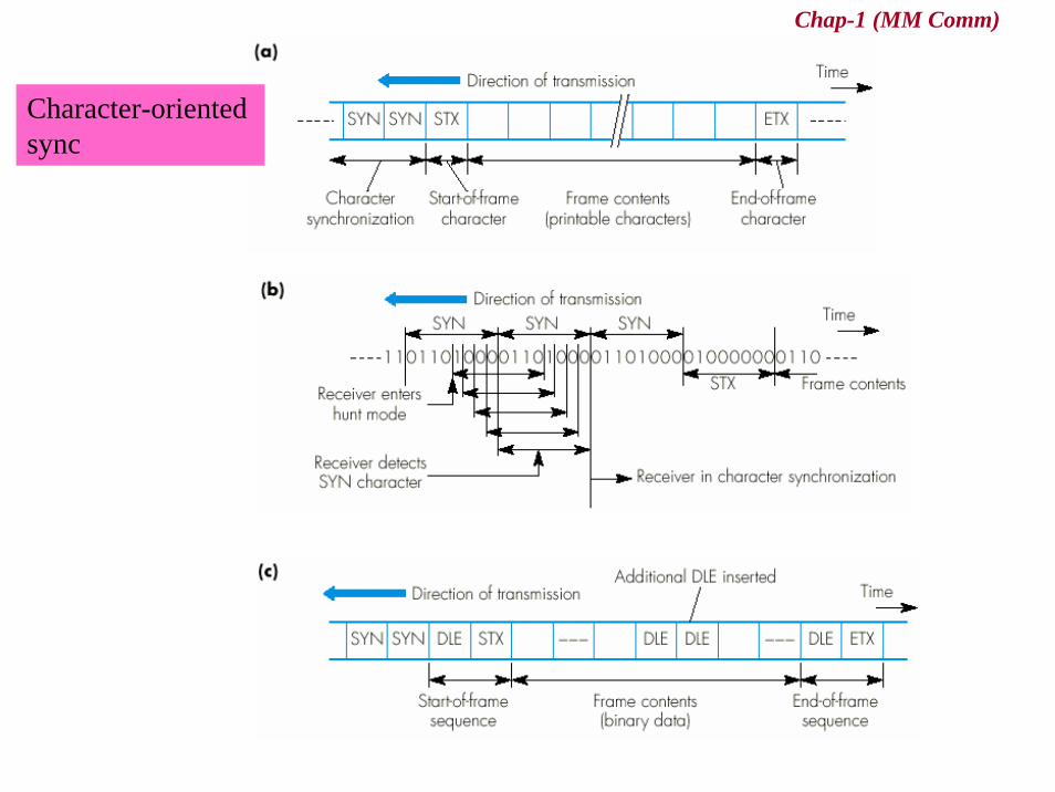
6.5 Synchronous Transmission (2)• Character-oriented sync
– SYN character– STX, ETX, DLE character
• Bit-oriented sync– an unique 8-bit pattern
• flag byte or flag pattern– idle byte
Chap-1 (MM Comm)
Character-oriented sync

Chap-1 (MM Comm)
Bit-oriented sync

Chap-1 (MM Comm)
Encoding
Chap-1 (MM Comm)
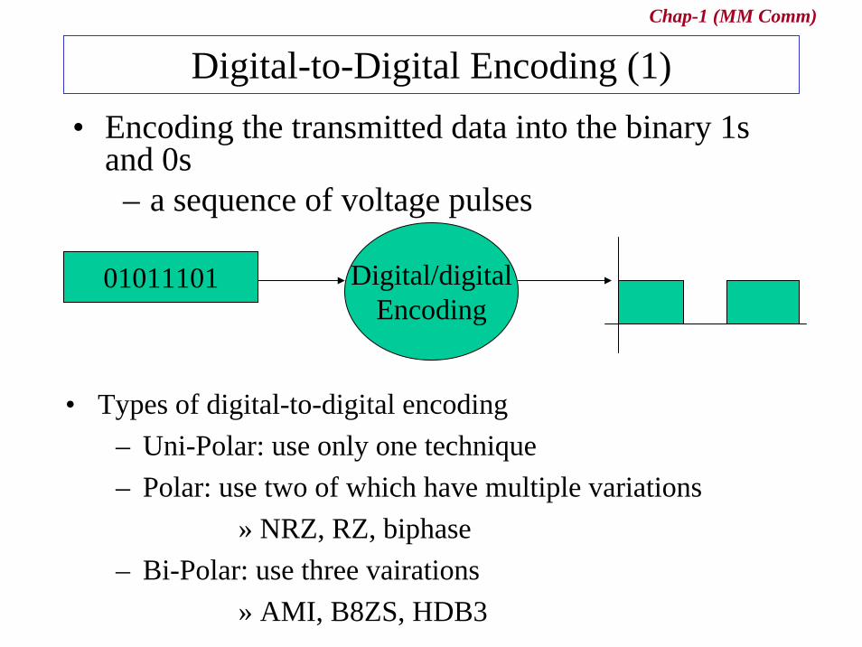
Digital-to-Digital Encoding (1)• Encoding the transmitted data into the binary 1s
and 0s– a sequence of voltage pulses
01011101 Digital/digitalEncoding
• Types of digital-to-digital encoding– Uni-Polar: use only one technique– Polar: use two of which have multiple variations
» NRZ, RZ, biphase– Bi-Polar: use three vairations
» AMI, B8ZS, HDB3
Chap-1 (MM Comm)
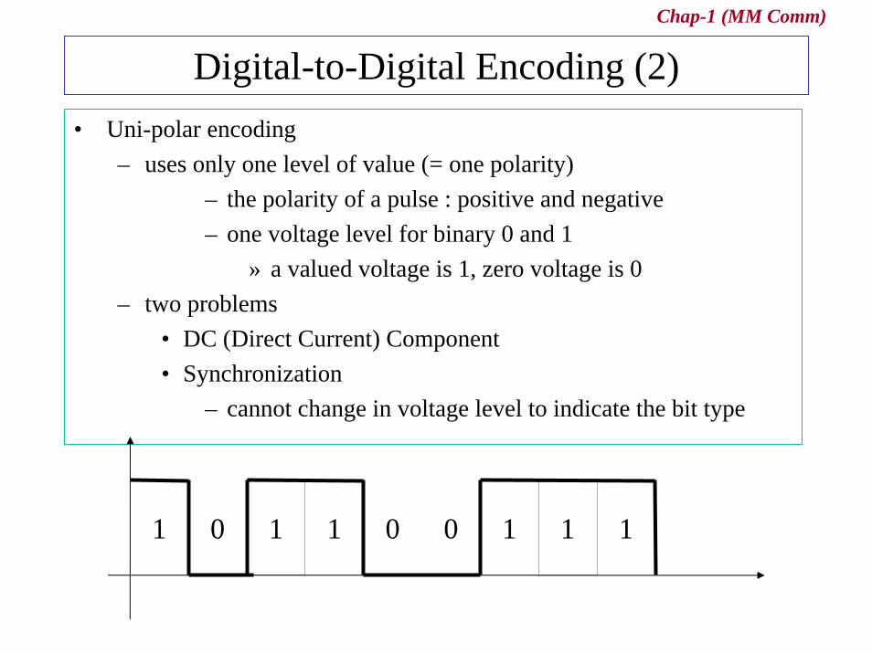
Digital-to-Digital Encoding (2)• Uni-polar encoding
– uses only one level of value (= one polarity)– the polarity of a pulse : positive and negative– one voltage level for binary 0 and 1
» a valued voltage is 1, zero voltage is 0– two problems
• DC (Direct Current) Component• Synchronization
– cannot change in voltage level to indicate the bit type
1 1 11110 00
Chap-1 (MM Comm)
Digital-to-Digital Encoding (3)
• Polar– uses two voltage levels (one positive and negative) of amplitude
– DC Component is eliminated by Manchester» binary 1: a negative-to-positive transition» binary 0: a positive-to-negative transition
– Types of polar encoding• Non-Return to zero (NRZ)
– Non-Return to zero , Level (NRZ-L) – Non-Return to zero , Invert (NRZ-L)
• Return to Zero (RZ) : Sync• Biphasea: Sync
– Manchester– Differential Manchester
Chap-1 (MM Comm)
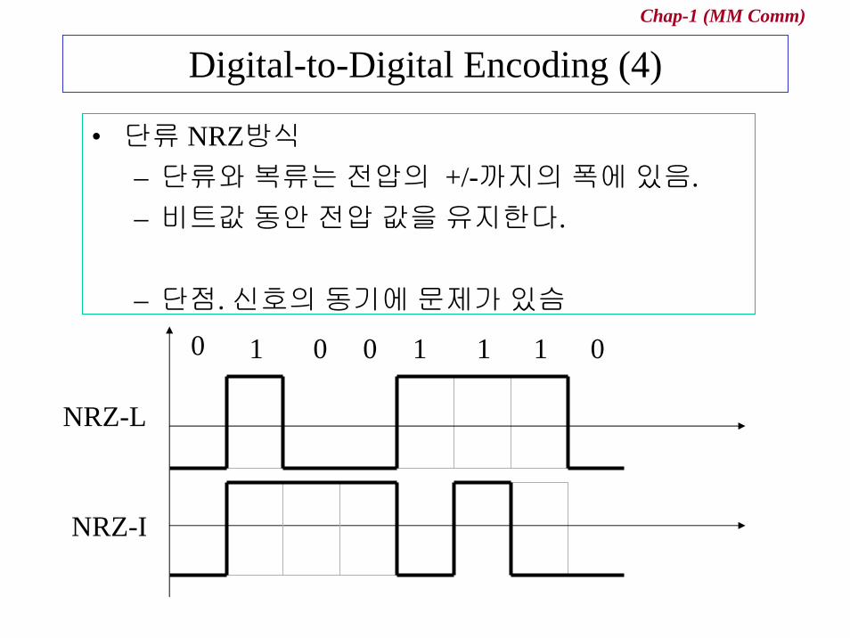
Digital-to-Digital Encoding (4)
• 단류 NRZ방식– 단류와복류는전압의 +/-까지의폭에있음.– 비트값동안전압값을유지한다.
– 단점. 신호의동기에문제가있슴0 1 0 0 1 1 1 0
NRZ-L
NRZ-I
Chap-1 (MM Comm)
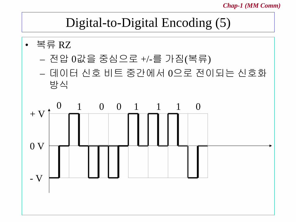
Digital-to-Digital Encoding (5)• 복류 RZ
– 전압 0값을중심으로 +/-를가짐(복류)– 데이터신호비트중간에서 0으로전이되는신호화방식
0 1 0 0 1 1 1 0
0 V
+ V
- V
Chap-1 (MM Comm)
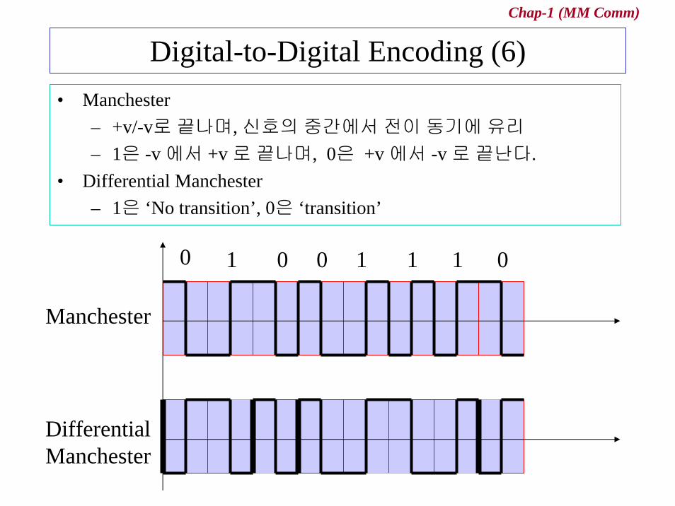
Digital-to-Digital Encoding (6)• Manchester
– +v/-v로끝나며, 신호의중간에서전이동기에유리– 1은 -v 에서 +v 로끝나며, 0은 +v 에서 -v 로끝난다.
• Differential Manchester– 1은 ‘No transition’, 0은 ‘transition’
0 1 0 0 1 1 1 0
Manchester
DifferentialManchester
Chap-1 (MM Comm)
Digital-to-Digital Encoding (7)• Bi-Polar
– like RZ; uses three voltage levels: + , -, zero– unlike RZ
• zero level is binary 0
– Three type• Alternate Mark Inversion (AMI)
– the simplest type of bipolar encoding• Bipolar 8-Zero Substitution (B8ZS)
– adopted in Noth America– forces artificial changes, called violations within the 0
string• High-Density Bipolar 3 (HDB3)
– used in Europe and Japan– every time four consecutive 0’s

Chap-1 (MM Comm)
Digital-to-Digital Encoding (8)
• AMI (Alternate mark Inversion)– zero voltage is binary 0– alternate is 1 inversion– 앞의 1이 +v이면다음 1은 -v를가짐
0 1 0 0 1 1 1 0
AMI 0 V
+ V
- V
Chap-1 (MM Comm)
6.6 Error detection methods• Error Detection and Correction
– For reliable communication• Data can be corrupted during transmission• Errors must be detected and corrected
– Data link layer– Transport layer
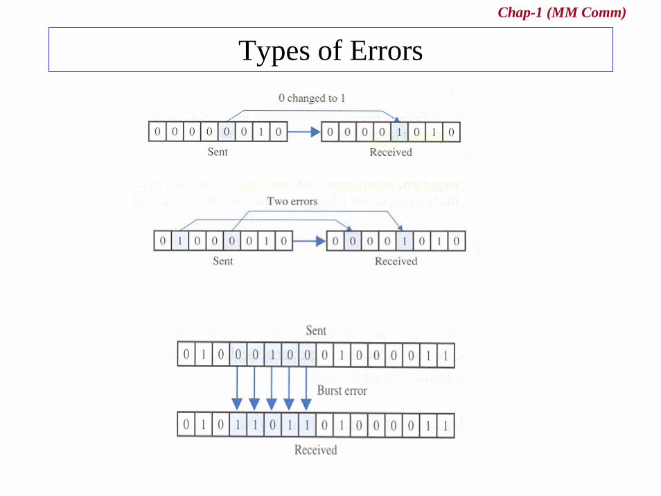
• Types of errors– Single-Bit Error
• means that only one bit of a given data unit is changed– Multiple-Bir Error
• means that two or or more nonconsecutive bits in a data unit have changed
– Burst Error• means that two or more consecutive bits in a data unit have
changed
Chap-1 (MM Comm)
Types of Errors
Chap-1 (MM Comm)
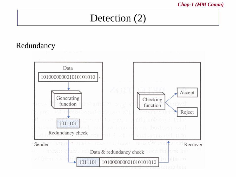
Detection (1)• Error Detection
– uses the concept of redundancy, which means adding extra bits for detecting errors at the destination
• Detection Methods– Vertical Redundancy Check (VRC) : called Parity check– Longitudinal Redundancy Check (LRC)
• two dimension of VRC– Cyclic Redundancy Check (CRC)– Checksum
– VRC, LRC, CRC : are implemented in the physical layer for use in the data link layer
– Checksum: is implemented in the transport layer
Chap-1 (MM Comm)
Detection (2)
Redundancy
Chap-1 (MM Comm)
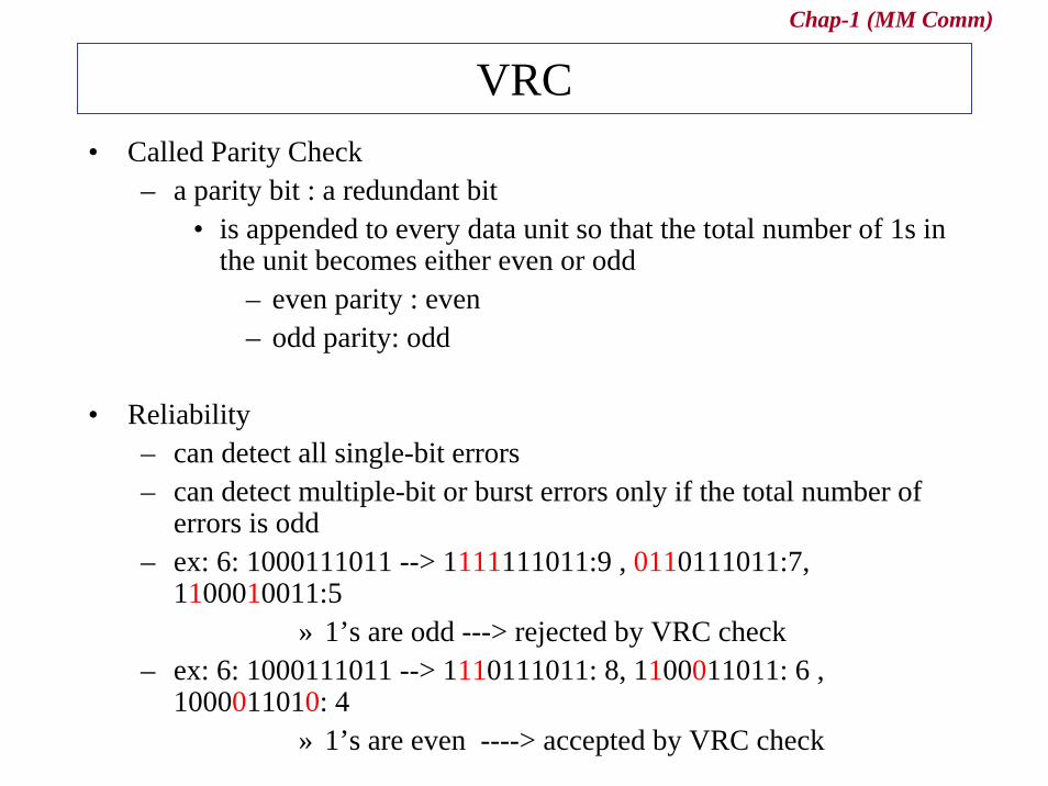
VRC• Called Parity Check
– a parity bit : a redundant bit• is appended to every data unit so that the total number of 1s in
the unit becomes either even or odd– even parity : even– odd parity: odd
• Reliability– can detect all single-bit errors– can detect multiple-bit or burst errors only if the total number of
errors is odd– ex: 6: 1000111011 --> 1111111011:9 , 0110111011:7,
1100010011:5» 1’s are odd ---> rejected by VRC check
– ex: 6: 1000111011 --> 1110111011: 8, 1100011011: 6 , 1000011010: 4
» 1’s are even ----> accepted by VRC check

Chap-1 (MM Comm)
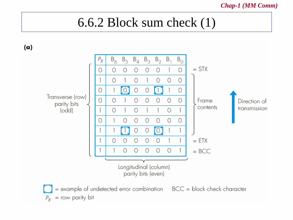
LRC• To increase the detecting of multiple-bit and burst errors
– groups a predetermined number of data units, each already containing a VRC parity bit
• A redundant unit is added after a number of data units– The bits in the redundant unit are calculated from the
corresponding bits in the data units using VRC
• Reliability– increases the detecting of multiple-bit and burst errors– exist one pattern of errors
• if two bits in exactly the same positions • ex two data units: 11110000 and 11000011
» 01110001 and 01000010 (00110011)
Chap-1 (MM Comm)
6.6.2 Block sum check (1)
Chap-1 (MM Comm)
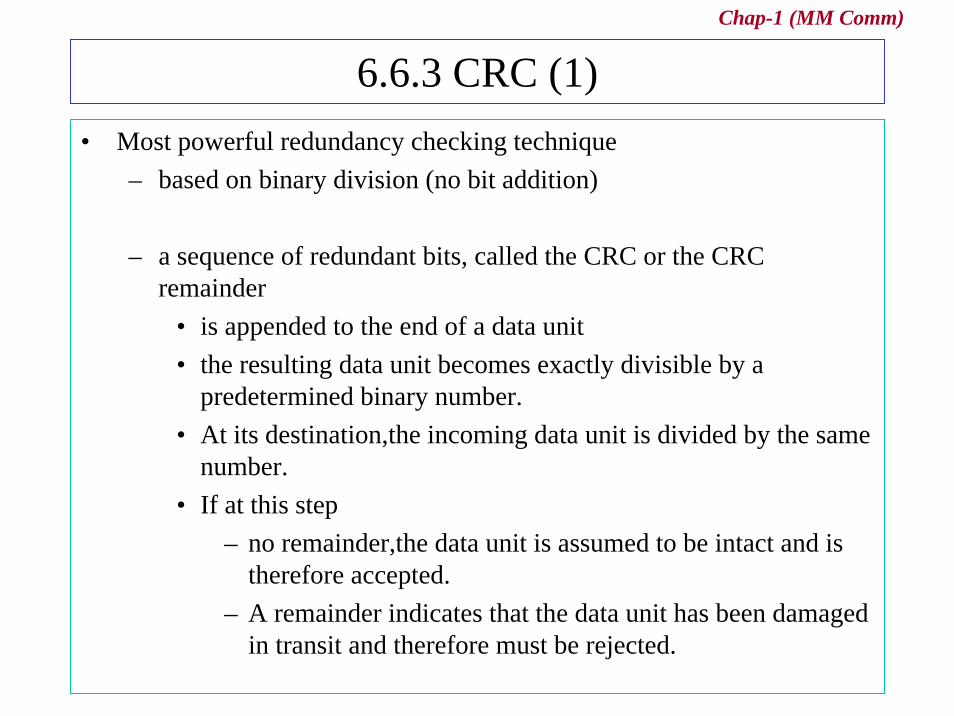
6.6.3 CRC (1)• Most powerful redundancy checking technique
– based on binary division (no bit addition)
– a sequence of redundant bits, called the CRC or the CRC remainder
• is appended to the end of a data unit • the resulting data unit becomes exactly divisible by a
predetermined binary number.• At its destination,the incoming data unit is divided by the same
number.• If at this step
– no remainder,the data unit is assumed to be intact and is therefore accepted.
– A remainder indicates that the data unit has been damaged in transit and therefore must be rejected.
Chap-1 (MM Comm)
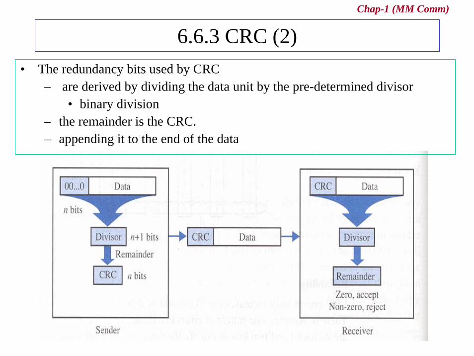
6.6.3 CRC (2)• The redundancy bits used by CRC
– are derived by dividing the data unit by the pre-determined divisor• binary division
– the remainder is the CRC. – appending it to the end of the data
Chap-1 (MM Comm)
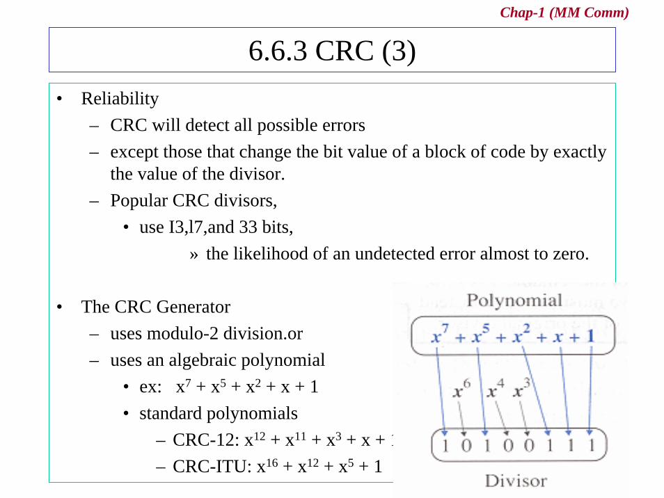
6.6.3 CRC (3)• Reliability
– CRC will detect all possible errors – except those that change the bit value of a block of code by exactly
the value of the divisor.– Popular CRC divisors,
• use I3,l7,and 33 bits, » the likelihood of an undetected error almost to zero.
• The CRC Generator– uses modulo-2 division.or– uses an algebraic polynomial
• ex: x7 + x5 + x2 + x + 1 • standard polynomials
– CRC-12: x12 + x11 + x3 + x + 1 – CRC-ITU: x16 + x12 + x5 + 1

Chap-1 (MM Comm)
6.6.3 CRC (4)
Chap-1 (MM Comm)
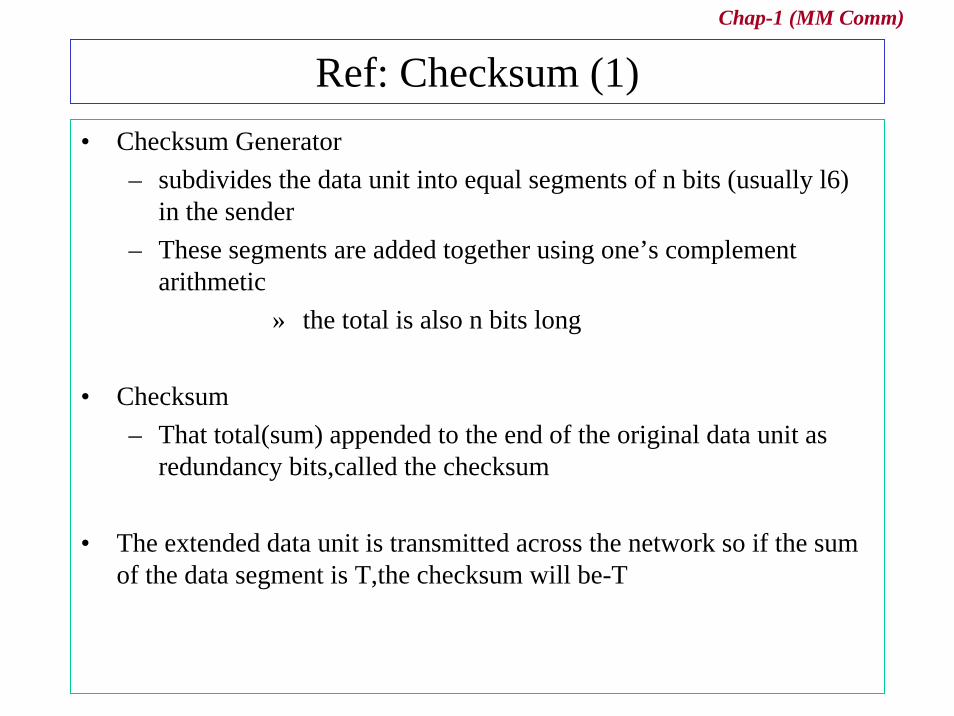
Ref: Checksum (1)• Checksum Generator
– subdivides the data unit into equal segments of n bits (usually l6) in the sender
– These segments are added together using one’s complement arithmetic
» the total is also n bits long
• Checksum – That total(sum) appended to the end of the original data unit as
redundancy bits,called the checksum
• The extended data unit is transmitted across the network so if the sum of the data segment is T,the checksum will be-T
Chap-1 (MM Comm)
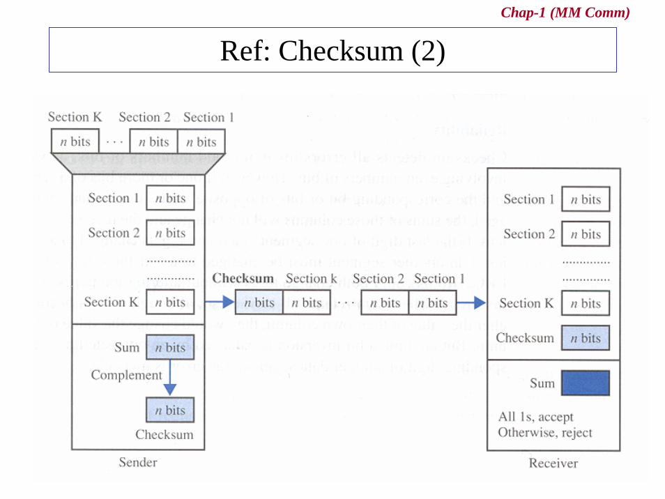
Ref: Checksum (2)
Chap-1 (MM Comm)
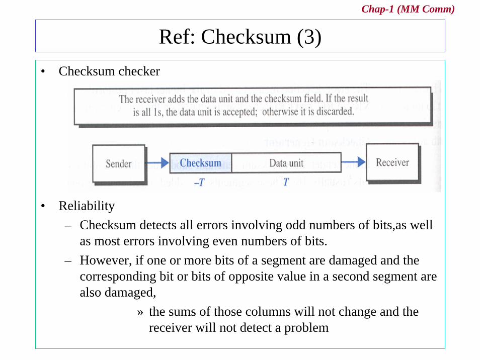
Ref: Checksum (3)• Checksum checker
• Reliability– Checksum detects all errors involving odd numbers of bits,as well
as most errors involving even numbers of bits.– However, if one or more bits of a segment are damaged and the
corresponding bit or bits of opposite value in a second segment are also damaged,
» the sums of those columns will not change and the receiver will not detect a problem
Chap-1 (MM Comm)
Ref: Error Correction• Two ways
– have the sender retransmit the entire data unit– use an error-correcting code
• more sophisticated • require more redundancy bits
» limited to one, two, three-bit errors
• A single-bit error correction – redundancy bits to indicate the location of the error bit
• data bits (m) + redundancy bits ( r) --> m + r bits• different states : 2r
• see table 9.1 : relationship between data and redundancy bits
– Hamming code
Chap-1 (MM Comm)
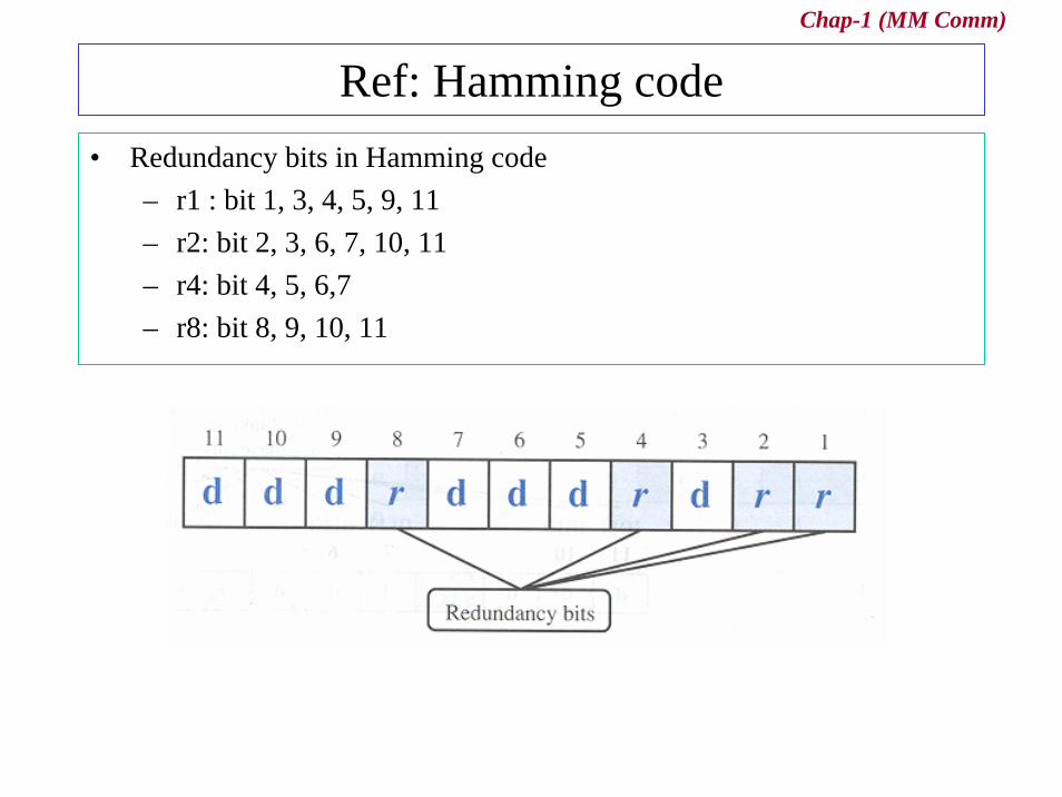
Ref: Hamming code• Redundancy bits in Hamming code
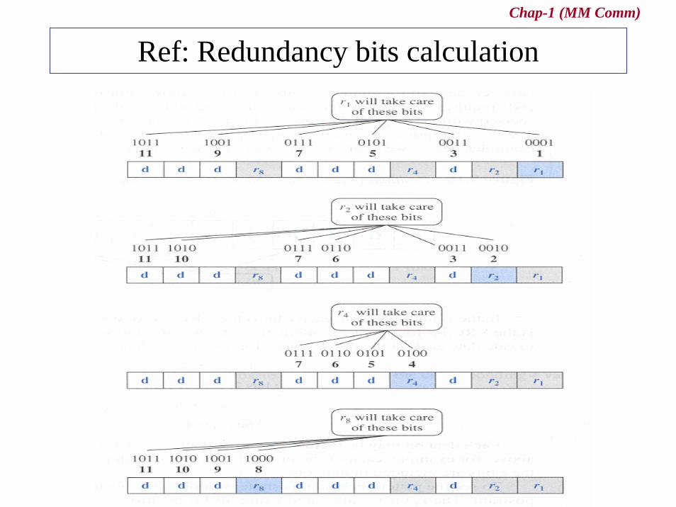
– r1 : bit 1, 3, 4, 5, 9, 11– r2: bit 2, 3, 6, 7, 10, 11– r4: bit 4, 5, 6,7– r8: bit 8, 9, 10, 11
Chap-1 (MM Comm)
Ref: Redundancy bits calculation
Chap-1 (MM Comm)
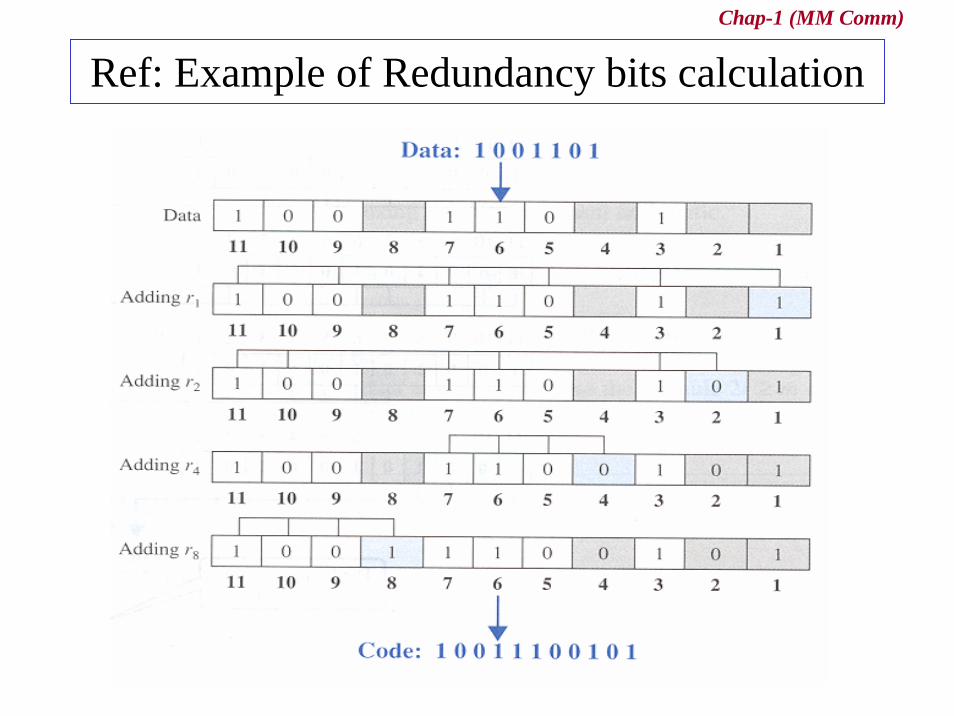
Ref: Example of Redundancy bits calculation
Chap-1 (MM Comm)
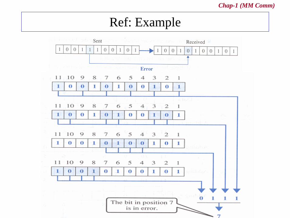
Ref: Example
Chap-1 (MM Comm)
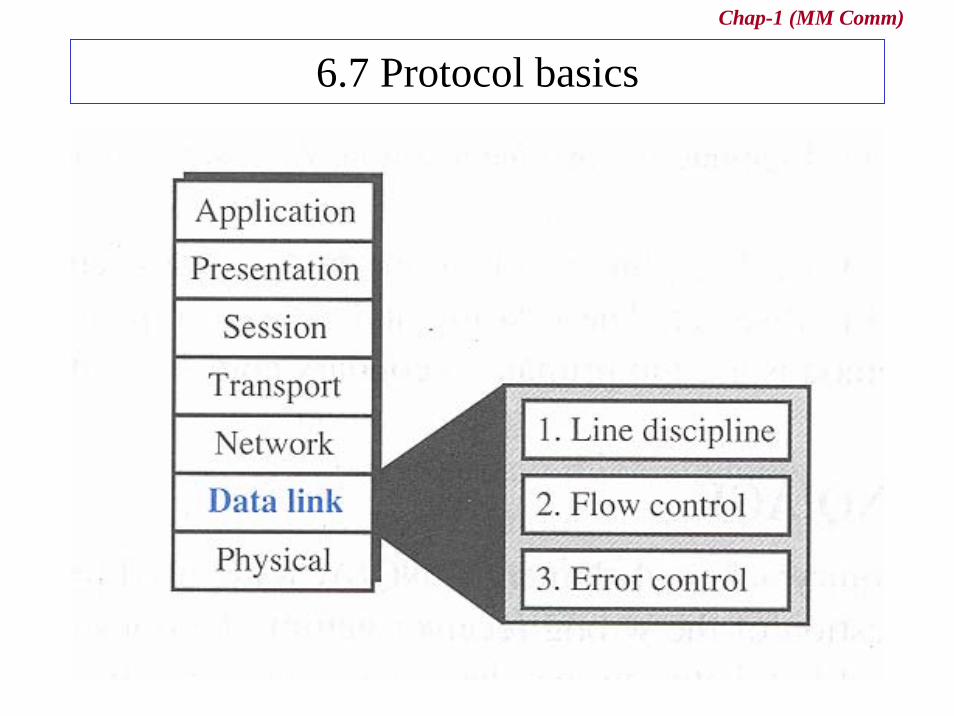
6.7 Protocol basics
Chap-1 (MM Comm)
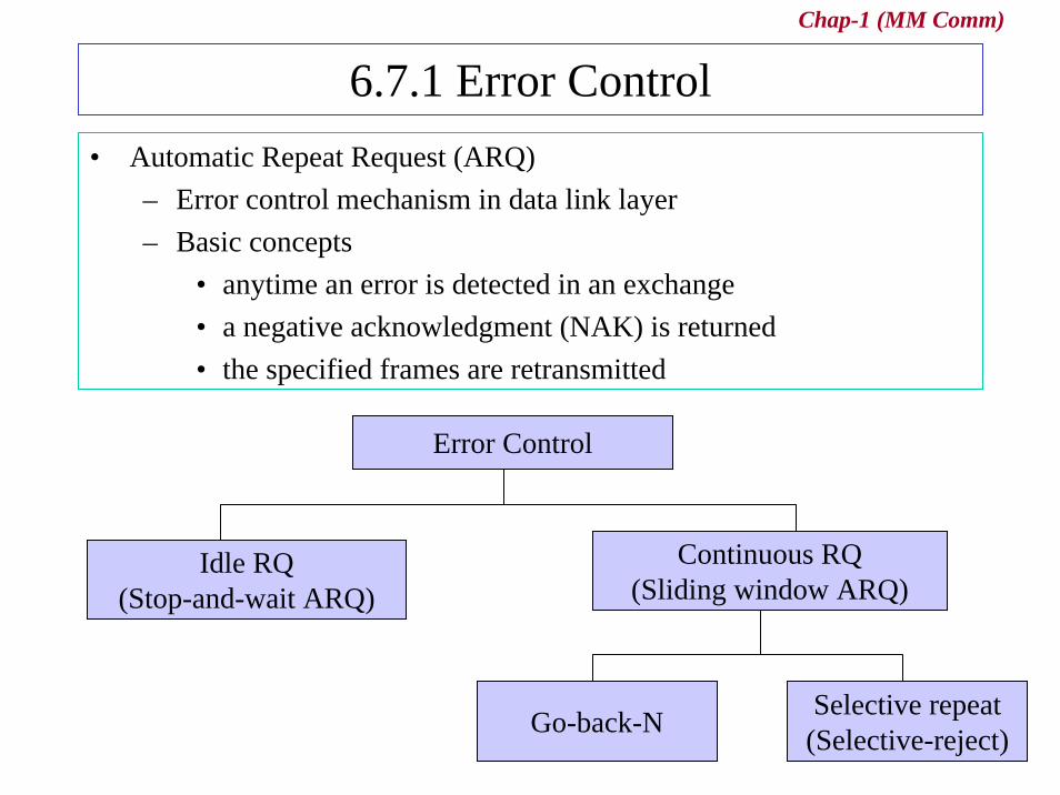
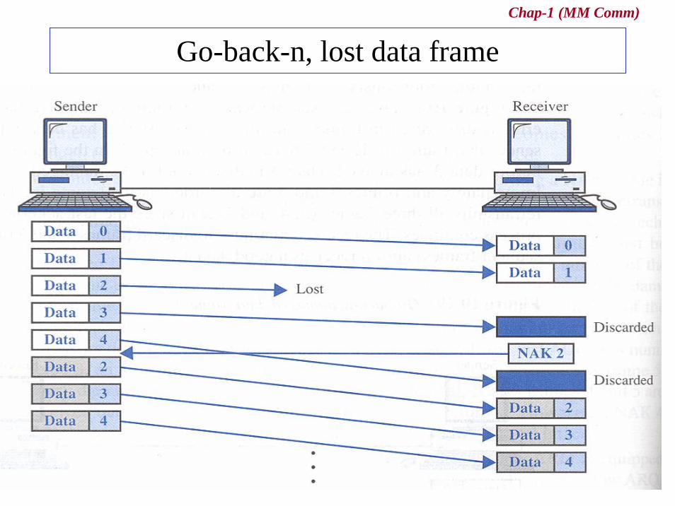
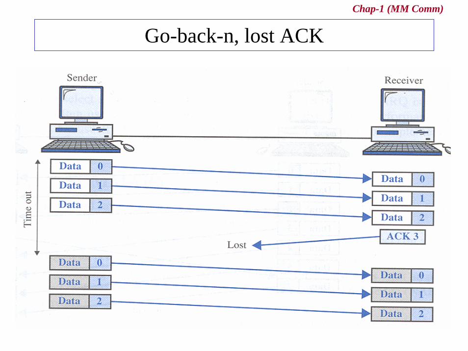
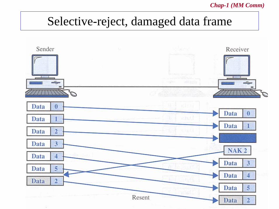
6.7.1 Error Control• Automatic Repeat Request (ARQ)
– Error control mechanism in data link layer– Basic concepts
• anytime an error is detected in an exchange• a negative acknowledgment (NAK) is returned• the specified frames are retransmitted
Error Control
Idle RQ(Stop-and-wait ARQ)
Continuous RQ(Sliding window ARQ)
Selective repeat(Selective-reject)Go-back-N

Chap-1 (MM Comm)
Stop-and-wait ARQ, damaged frame
Chap-1 (MM Comm)
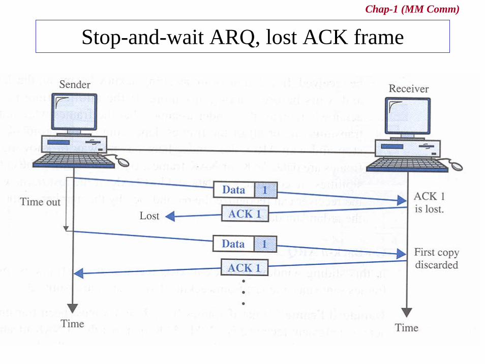
Stop-and-wait ARQ, lost ACK frame
Chap-1 (MM Comm)
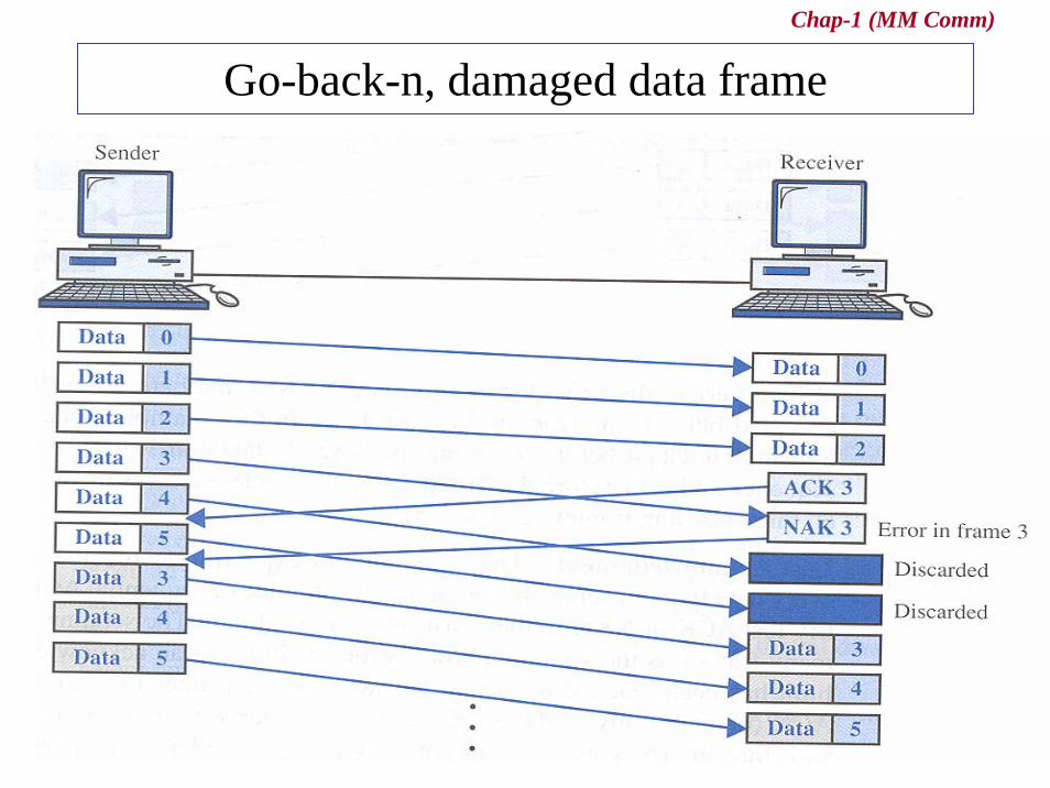
Go-back-n, damaged data frame
Chap-1 (MM Comm)
Go-back-n, lost data frame
Chap-1 (MM Comm)
Go-back-n, lost ACK
Chap-1 (MM Comm)
Selective-reject, damaged data frame
Chap-1 (MM Comm)
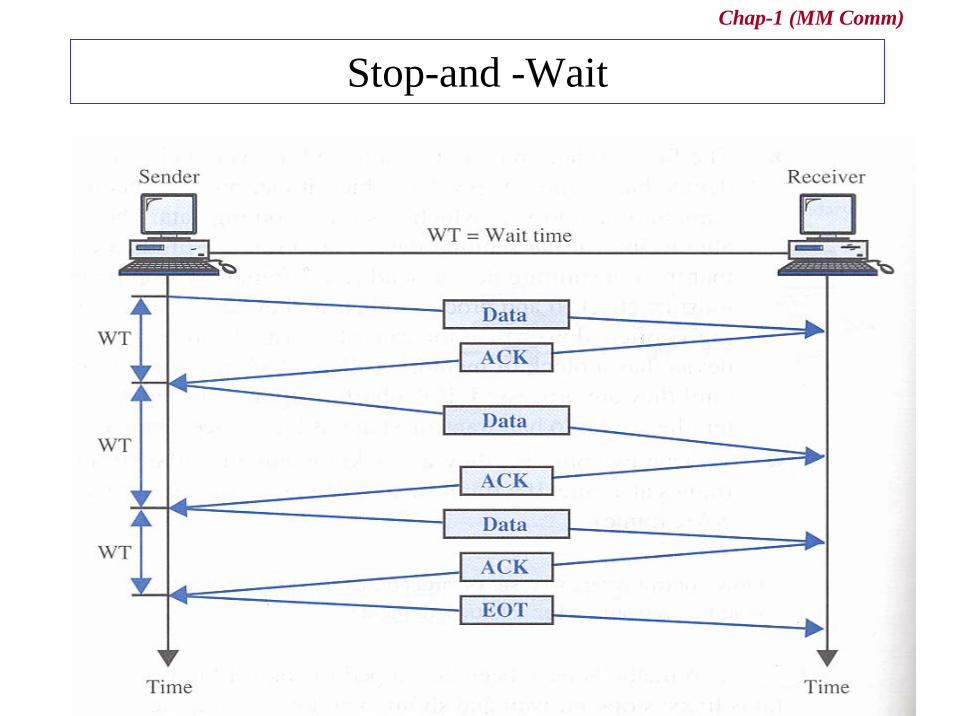
6.7.4 Flow Control• Flow Control
– refers to a set of procedures used to restrict the amount of data the sender can send before waiting for acknowledgment
– Two ways• Stop-and-Wait
– Send one frame at a time– the sender sends one frame and waits for an
acknowledgement before sending the next frame
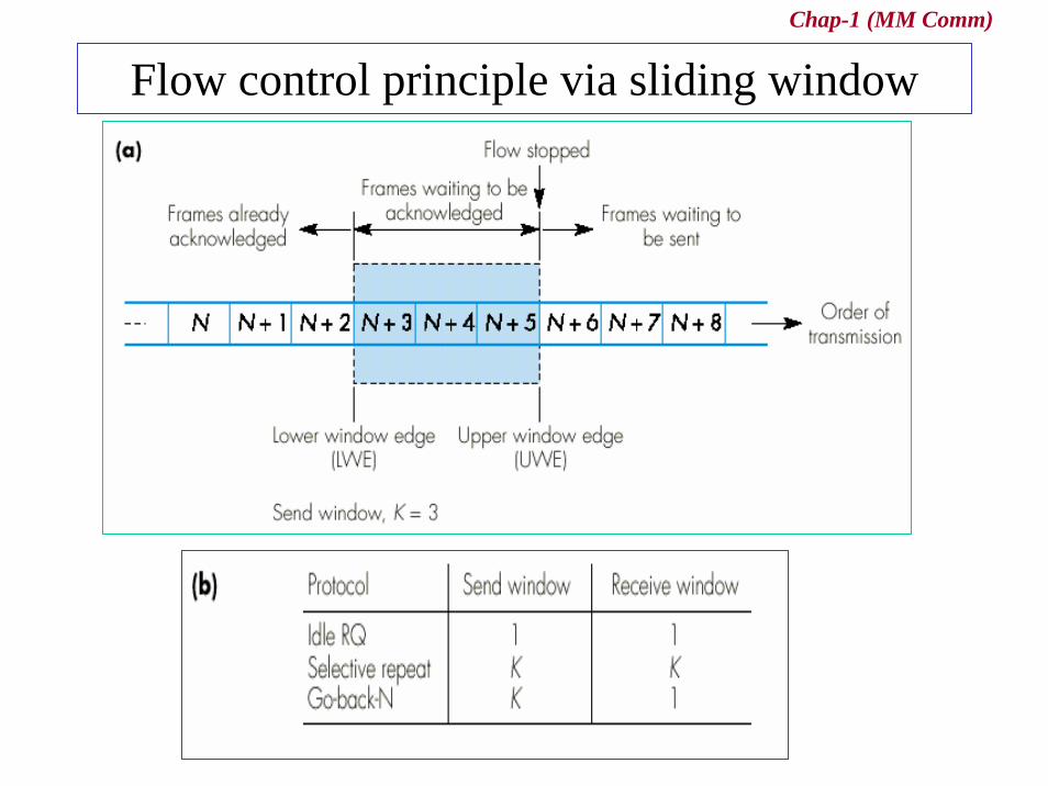
• Sliding Window– Send several frames at a time– several frames can be in transit at a time
Chap-1 (MM Comm)
Stop-and -Wait
Chap-1 (MM Comm)
Flow control principle via sliding window
Chap-1 (MM Comm)
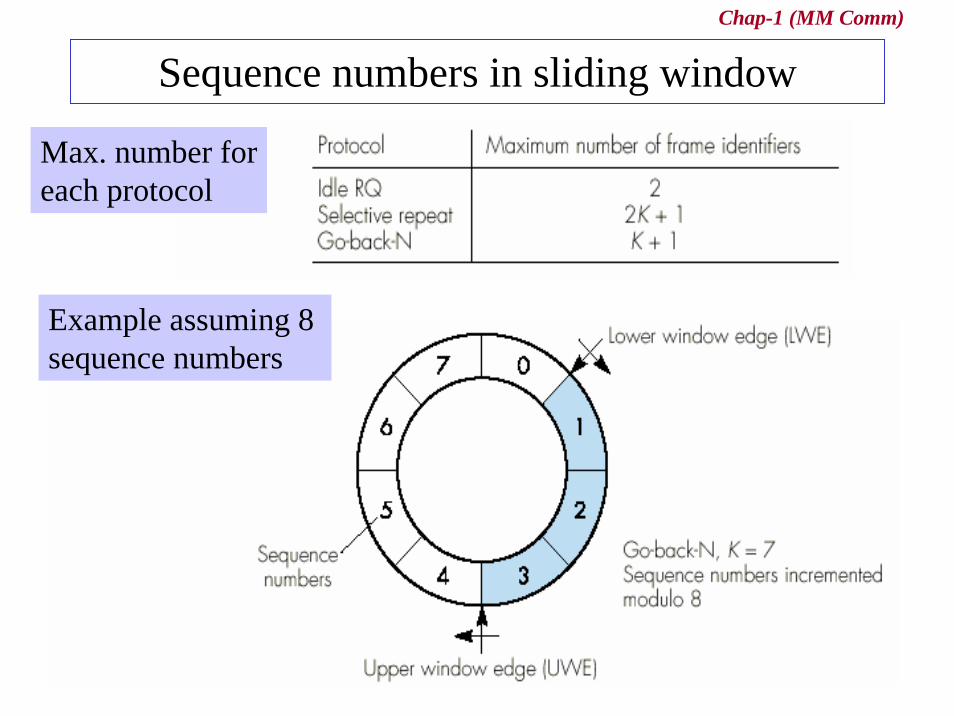
Sequence numbers in sliding window
Max. number foreach protocol
Example assuming 8 sequence numbers

Chap-1 (MM Comm)
Example of Sliding Windows
Chap-1 (MM Comm)
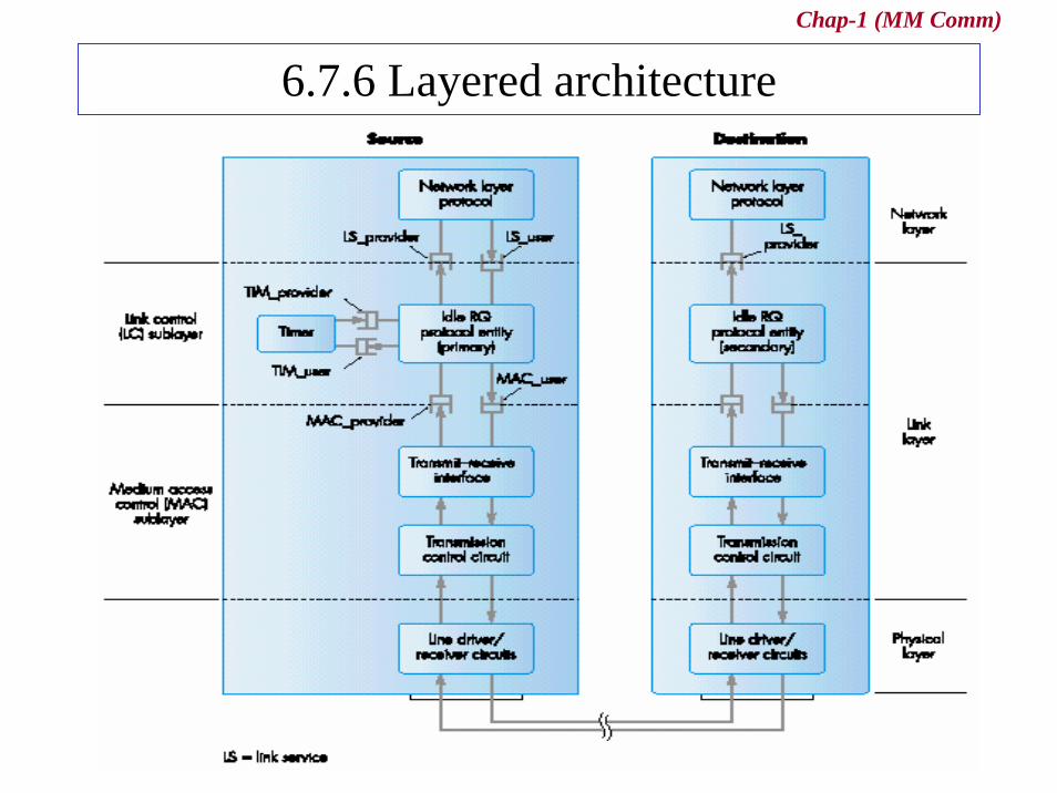
6.7.6 Layered architecture
Chap-1 (MM Comm)
6.8 The HDLC protocol• High-level Data Link Control (HDLC) protocol
– logical link layer protocol in data link protocol
• A data link protocol– a set of specifications used to implement the data link layer
• Two categories– Asynchronous protocol
• treats each character in a bit stream independently
– Synchronous protocol• takes the whole bit stream and chop it into characters of equal
size
Chap-1 (MM Comm)
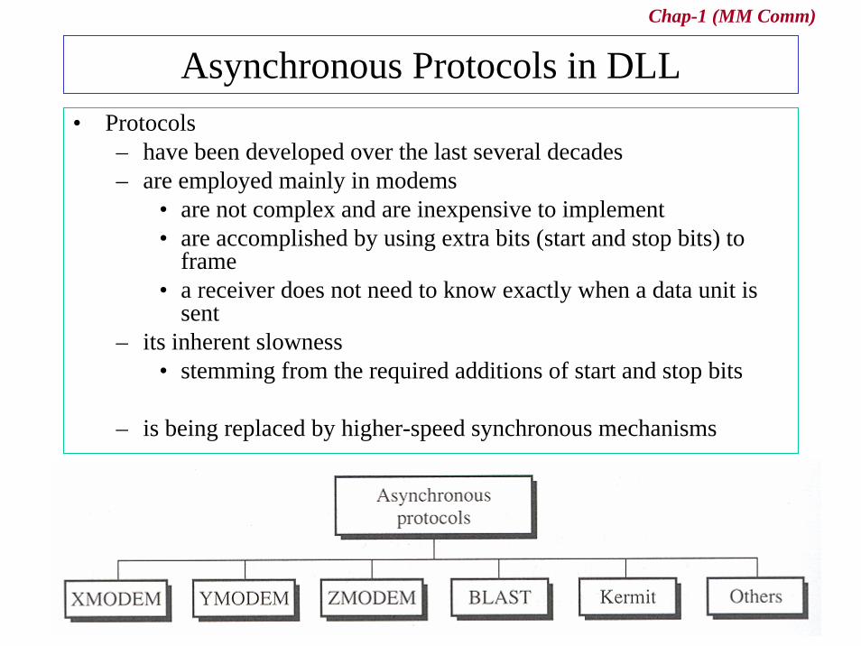
Asynchronous Protocols in DLL• Protocols
– have been developed over the last several decades– are employed mainly in modems
• are not complex and are inexpensive to implement• are accomplished by using extra bits (start and stop bits) to
frame• a receiver does not need to know exactly when a data unit is
sent– its inherent slowness
• stemming from the required additions of start and stop bits
– is being replaced by higher-speed synchronous mechanisms
Chap-1 (MM Comm)
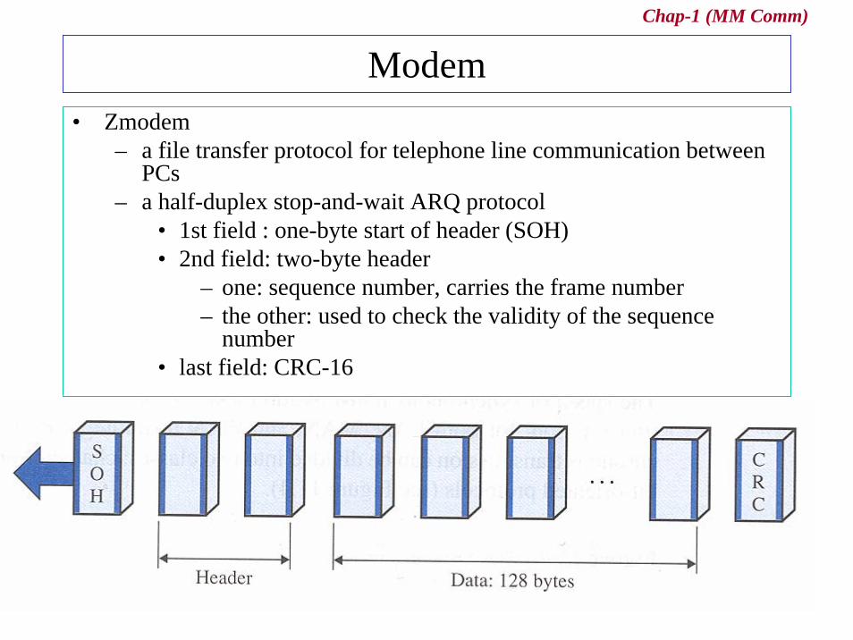
Modem• Zmodem
– a file transfer protocol for telephone line communication between PCs
– a half-duplex stop-and-wait ARQ protocol• 1st field : one-byte start of header (SOH)• 2nd field: two-byte header
– one: sequence number, carries the frame number– the other: used to check the validity of the sequence
number• last field: CRC-16
Chap-1 (MM Comm)
Synchronous Protocols in DLL• The better choice for LAN, WAN technology
– High speed over asynchronous transmission
• Two types– Character oriented protocol
• interpret a transmission frame or packet as a succession of characters
» composed of byte, called byte-oriented protocol• all information is encoded to ASCII characters
– Bit oriented protocol• interpret a transmission frame or packet as a succession of
individual bits• all information is depended in the bit position or pattern

Chap-1 (MM Comm)
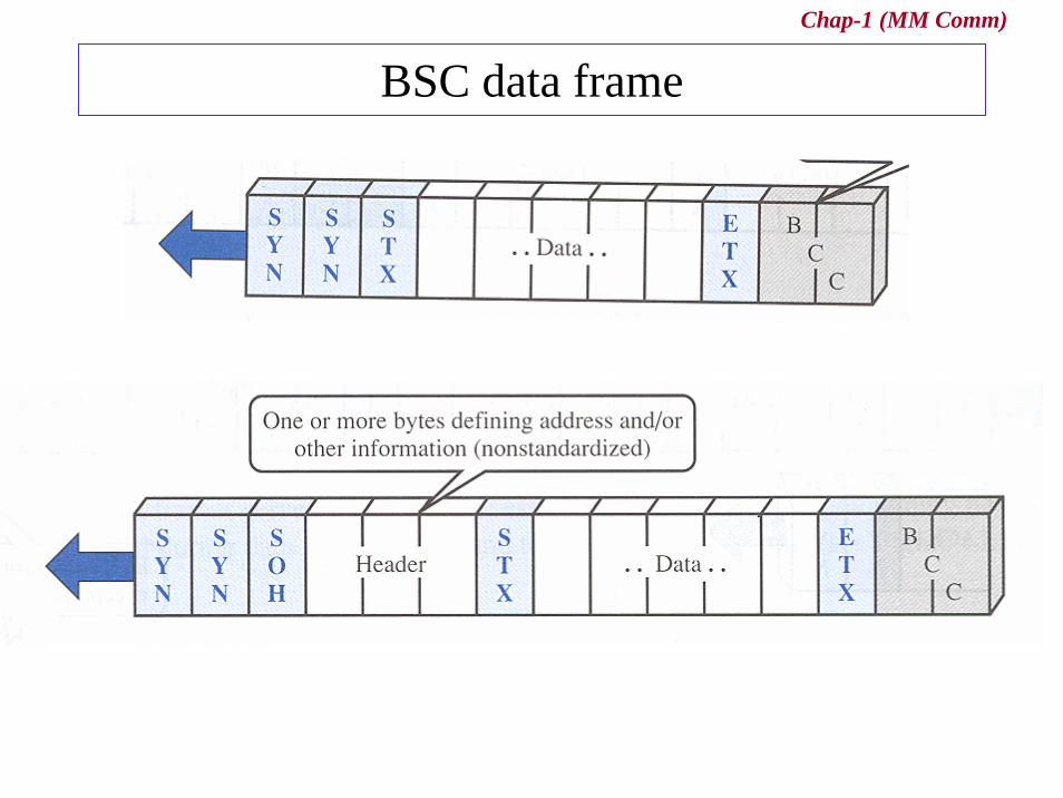
Character-oriented protocol in DLL• Binary Synchronous Communication
– a popular character-oriented data link protocol developed by IBM in 1964
– supports half-duplex transmission using stop-and-wait ARQ– does not support full-duplex transmission or sliding window
protocol
– BASC Frames• Control frames
– connection, flow and error control, and disconnection• Data frames
– transmission of data
Chap-1 (MM Comm)
BSC data frame
Chap-1 (MM Comm)
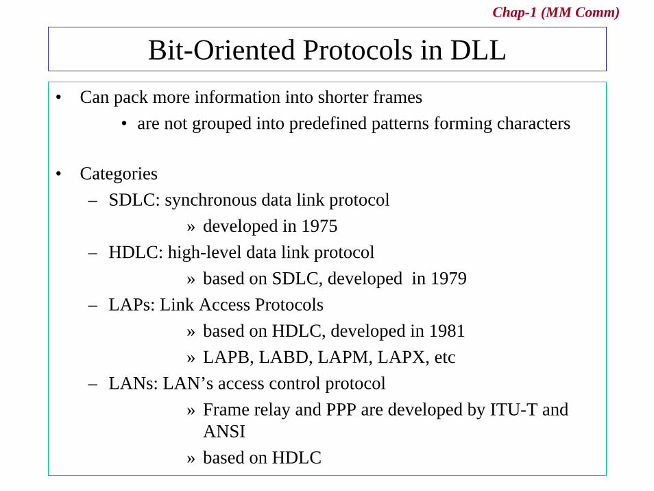
Bit-Oriented Protocols in DLL• Can pack more information into shorter frames
• are not grouped into predefined patterns forming characters
• Categories– SDLC: synchronous data link protocol
» developed in 1975– HDLC: high-level data link protocol
» based on SDLC, developed in 1979– LAPs: Link Access Protocols
» based on HDLC, developed in 1981» LAPB, LABD, LAPM, LAPX, etc
– LANs: LAN’s access control protocol» Frame relay and PPP are developed by ITU-T and
ANSI» based on HDLC
Chap-1 (MM Comm)
HDLC• HDLC
– a basis for all bit-oriented protocols– supports both half-duplex and full-duplex modes in point-to-point
and multi-point configuration– can be characterized by station types, configurations, and response
modes
• Station types– are of three types: primary, secondary, and combined
• primary: sends commands• secondary: sends responses• combined station: sends commands and responses
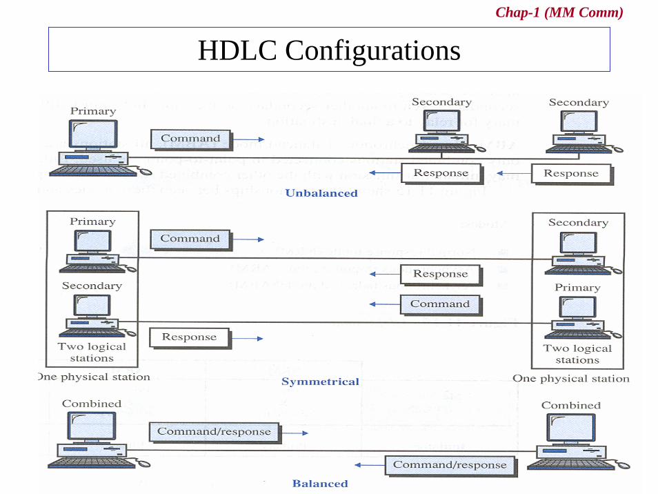
• Configurations– refers to the relationship of hardware devices on a link – primary or secondary between peers
Chap-1 (MM Comm)
HDLC Configurations
Chap-1 (MM Comm)
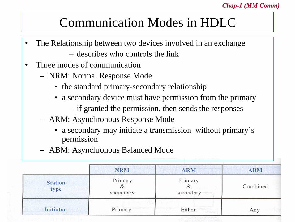
Communication Modes in HDLC• The Relationship between two devices involved in an exchange
– describes who controls the link• Three modes of communication
– NRM: Normal Response Mode• the standard primary-secondary relationship• a secondary device must have permission from the primary
– if granted the permission, then sends the responses– ARM: Asynchronous Response Mode
• a secondary may initiate a transmission without primary’s permission
– ABM: Asynchronous Balanced Mode

Chap-1 (MM Comm)
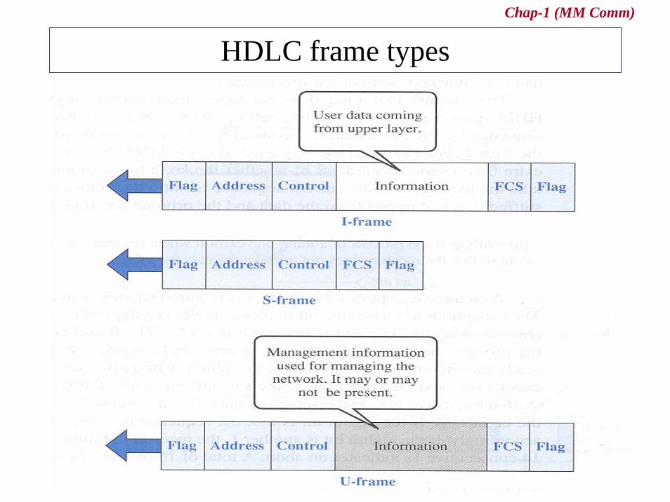
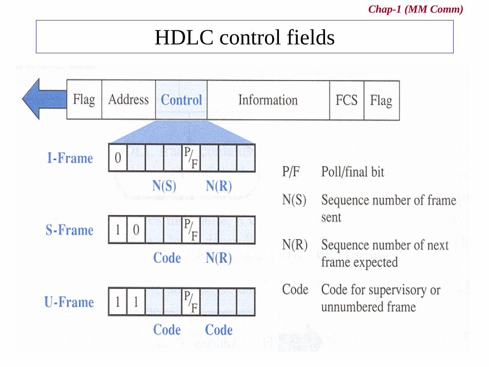
Frames in HDLC• Three types of frames
– Information frames (I-frames)• are used to transport user data and control information relating
to user data– Supervisory frames (S-frames)
• are used only to transport control information, primary data link layer flow and error controls
– Unnumbered frames (U-frames)• are reserved for system management • are intended for managing the link itself
• Six fields– a beginning flag, an address, a control, an information, a frame
check sequence (FCS), and an ending flag
Chap-1 (MM Comm)
HDLC frame types
Chap-1 (MM Comm)
HDLC control fields

Chap-1 (MM Comm)
Example of polling using HDLC
Chap-1 (MM Comm)
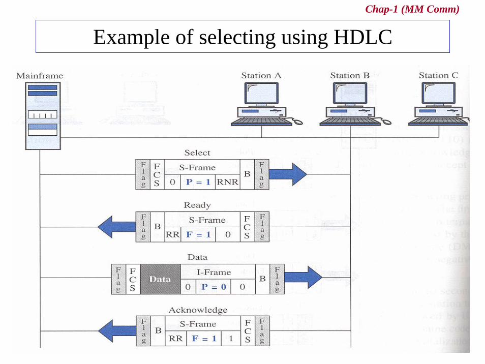
Example of selecting using HDLC
Chap-1 (MM Comm)
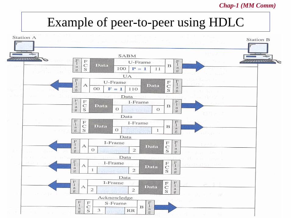
Example of peer-to-peer using HDLC
Chap-1 (MM Comm)
Link Access Procedures• LAPB (Link access procedure, for balanced)
• a simplified subset of HDLC used only for connecting a station to a network
• provides the basic control functions required for communication between a DTE and A DCE
• is used only in balanced configurations of two devices» be used in ISDN on B channel
• LAPD (Link access procedure, for D channel)– a simplified subset of HDLC used in ISDN
– uses ABM – is used for out-of-band (control) signaling
• LAPM (Link access procedure, for Modem)– a simplified subset of HDLC for modems
» has been developed to apply HDLC features to modems
– is designed to do asynchronous-synchronous conversion, error detection, and transmission

Chap-1 (MM Comm)
CF: DTE-DCE Interface (1)
• DTE: Data Terminal Equipment– any device that is a source of or destination for binary digital data
• DCE: Data Circuit-Terminating Equipment– any device that transmits or receives data in the form of an analog or
digital signal through a network
Chap-1 (MM Comm)
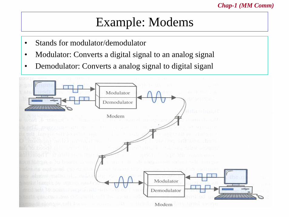
Example: Modems• Stands for modulator/demodulator• Modulator: Converts a digital signal to an analog signal• Demodulator: Converts a analog signal to digital siganl
![06-ComputerSecurityTechniques.ppt [호환 모드]mm.sookmyung.ac.kr/~bigrain/class/2012/mmos/06-ComputerSecurity... · cpu 에뮬레이터 바이러스서명스캐너 에뮬레이션제어모듈](https://img.pdfslide.net/doc/110x75/5e1857751a925f00a73fe34a/06-comput-eeoemmsookmyungackrbigrainclass2012mmos06-computersecurity.jpg)

![Mobile07 chap10 [읽기 전용] [호환 모드]mm.sookmyung.ac.kr/~sblim/lec/mobilemm/ppt/Mobile0… · · 2009-05-1310.1 무선메세징서비스의개념 10.1.1 sms의소개 10.1.2](https://img.pdfslide.net/doc/110x75/5aad94a17f8b9aa9488e7b26/mobile07-chap10-mm-sblimlecmobilemmpptmobile02009-05-13101.jpg)


![mm 02 env [호환 모드]mm.sookmyung.ac.kr/~sblim/lec/mm-intro/ppt/mm_02_env.pdf · §멀티미디어 콘텐츠 ... l이미지/그래픽(Image/Graphics) §Adobe SVG viewer, CMX viewer,](https://img.pdfslide.net/doc/110x75/5e1384d02b12115149050f51/mm-02-env-eeoemm-sblimlecmm-intropptmm02envpdf-eee.jpg)