Embed Size (px)
Citation preview
November 1, 2021 6-1
Chapter 6 Roadside Barriers6.1 General ConsiderationsRoadside barriers are generally used to prevent vehicles that leave the roadway from colliding with rigid objects or embankment slopes located along the side of the roadway or with vehicles coming in the opposite direction. Common types of barriers are steel beam guardrail, cable guiderail, and concrete barrier. This section of the RDM discusses specific types of barriers and their use.Use roadside safety hardware compliant with the AASHTO Manual for Assessing Safety Hardware (MASH) 2016 and NCDOT Memo September 11, 2017 Roadside Safety Hardware – MASH-16 Implementation Plan. The use of roadside barriers along the side of the roadway warrants careful consideration. Where applicable, adjust the design elements of the project to reduce or remove the need for roadside barriers.The preferred method of addressing roadside hazards is as follows:
1. Remove the hazard2. Remove embankment hazard (flatten slopes)3. Shift hazard away from traffic4. Reduce the impact severity by using breakaway posts5. Protect the hazard6. Delineate the hazard so motorists are aware of the hazard
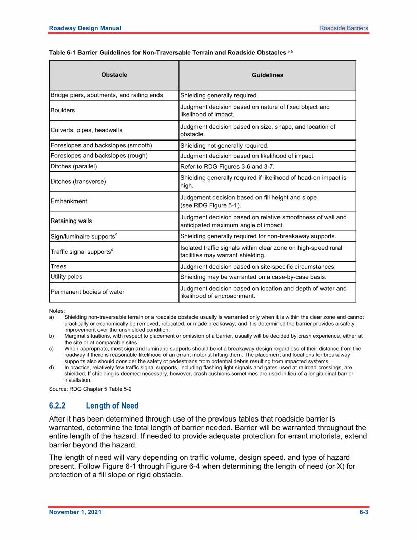
Refer to Table 6-1 below and GB Chapter 4 Section 4.10 for detailed discussion of roadside barriers.
6.2 Longitudinal BarriersLongitudinal barriers are roadside barriers placed parallel to the travel way to protect motorists from hazards along the side of the roadway. The most common type of longitudinal barrier in use today is the 12-foot 6-inch W-beam galvanized steel beam guardrail (noted as guardrail in the following information); however, other barrier types such as concrete or cable barrier may be more appropriate for a specific location. The following sections describe warrants and guidelines for locations where longitudinal barriers should be considered.
6.2.1 Barrier WarrantsConsider use of a protective barrier, or barrier warrant, when it has been determined that impacts to the protective barrier will be less severe than impact with the roadside hazard. Design barrier warrants in accordance with the AASHTO Roadside Design Guide 4th Edition (RDG). When determining barrier warrants, an important concept to understand is clear zone. From the RDG: “a clear zone is the unobstructed, traversable area provided beyond the edge of the through traveled way for the recovery of errant vehicles. The zone includes shoulders, bike lanes, and auxiliary lanes, except those auxiliary lanes that function like through lanes”.
Roadway Design Manual Roadside Barriers
November 1, 2021 6-2
Refer to RDM Part I Chapter 4 Section 4.6 for more information on the importance of clear zones.Establish the location and grade of the project so as to eliminate as much barrier as possible using these warrants.After location data is received, plans plotted, grades set, and initial templates determined, adhere to the following procedures:
1. Determine potential barrier locations or warrants using the clear zone guide and Table 6-1 below.
2. Determine if barrier can be eliminateda. Can the hazard be removed, relocated, or made breakaway?b. Does a cost effectiveness analysis justify flattening slopes?c. Include the additional costs for right of way, drainage, borrow, erosion control, and
clearing, in the initial cost of the slope-flattening alternative.d. Will the design decision increase impacts on wetlands?
3. Use the clear zone guide:a. Refer to RDM Part I Chapter 7 Section 7.5 for pipe end treatment guidelines for
cross drainage pipe within the safety zone.b. For large pipes or culverts that have openings within the clear zone, justify use
through the cost effectiveness program by either extending the pipes or culverts beyond the safety limits, leaving the drainage as it is without barrier protection, or using barrier to protect the hazard.
c. Check the ditch sections for any non-traversable front or back slope within the clear zone. The ditch may remain unshielded if the back slope is smooth and free from hazards.
d. If justified, check to see that all obstructions within the clear zone are removed, modified for safety, or protected by barrier.
e. Check landscape plans to be sure that reforestation is not proposed within the safety clearing limits.
f. On low volume, unpaved roadways, guardrail is generally warranted only for bridge rail protection. Refer to RDM Part I Chapter 5 Section 5.2 for guidelines pertaining to Sub Regional Tier Bridge Projects.
Roadway Design Manual Roadside Barriers
November 1, 2021 6-3
Table 6-1 Barrier Guidelines for Non-Traversable Terrain and Roadside Obstacles a,b
Notes:a) Shielding non-traversable terrain or a roadside obstacle usually is warranted only when it is within the clear zone and cannot
practically or economically be removed, relocated, or made breakaway, and it is determined the barrier provides a safety improvement over the unshielded condition.
b) Marginal situations, with respect to placement or omission of a barrier, usually will be decided by crash experience, either at the site or at comparable sites.
c) When appropriate, most sign and luminaire supports should be of a breakaway design regardless of their distance from the roadway if there is reasonable likelihood of an errant motorist hitting them. The placement and locations for breakaway supports also should consider the safety of pedestrians from potential debris resulting from impacted systems.
d) In practice, relatively few traffic signal supports, including flashing light signals and gates used at railroad crossings, are shielded. If shielding is deemed necessary, however, crash cushions sometimes are used in lieu of a longitudinal barrier installation.
Source: RDG Chapter 5 Table 5-2
6.2.2 Length of NeedAfter it has been determined through use of the previous tables that roadside barrier is warranted, determine the total length of barrier needed. Barrier will be warranted throughout the entire length of the hazard. If needed to provide adequate protection for errant motorists, extend barrier beyond the hazard. The length of need will vary depending on traffic volume, design speed, and type of hazard present. Follow Figure 6-1 through Figure 6-4 when determining the length of need (or X) for protection of a fill slope or rigid obstacle.
Guidelines
Shielding generally required.
Judgment decision based on nature of fixed object and likelihood of impact.
Judgment decision based on size, shape, and location of obstacle.
Shielding not generally required.
Judgment decision based on likelihood of impact.
Refer to RDG Figures 3-6 and 3-7.
Shielding generally required if likelihood of head-on impact is high.
Judgement decision based on fill height and slope (see RDG Figure 5-1).
Judgment decision based on relative smoothness of wall and anticipated maximum angle of impact.
Shielding generally required for non-breakaway supports.
Isolated traffic signals within clear zone on high-speed rural facilities may warrant shielding.
Judgment decision based on site-specific circumstances.
Shielding may be warranted on a case-by-case basis.
Judgment decision based on location and depth of water and likelihood of encroachment.
Notes:
Permanent bodies of water
Trees
a) Shielding nontraversable terrain or a roadside obstacle usually is warranted only when it is within the clear zone and cannot practically or economically be removed, relocated, or made breakaway, and it is determined that the barrier provides a safety improvement over the unshielded condition.
b) Marginal situations, with respect to placement or omission of a barrier, usually will be decided by crash experience, either at the site or at comparable sites.
Source: RDG Table 5-2.
c) When appropriate, most sign and luminaire supports should be of a breakaway design regardless of their distance from the roadway if there is reasonable likelihood of an errant motorist hitting them. The placement and locations for breakaway supports also should consider the safety of pedestrians from potential debris resulting from impacted systems.
d) In practice, relatively few traffic signal supports, including flashing light signals and gates used at railroad crossings, are shielded. If shielding is deemed necessary, however, crash cushions sometimes are used in lieu of a longitudinal barrier installation.
Obstacle
Bridge piers, abutments, and railing ends
Boulders
Culverts, pipes, headwalls
Foreslopes and backslopes (smooth)
Foreslopes and backslopes (rough)
Ditches (parallel)
Ditches (transverse)
Embankment
Retaining walls
Sign/luminaire supportsc
Traffic signal supportsd
Utility poles

Roadway Design Manual Roadside Barriers
November 1, 2021 6-4
Note: Do not leave a space of less than 300 feet between guardrail installations. Extend the guardrail through the area if less than 300 feet exists between installations.Refer to RDG Chapter 5 Section 5.6.4 for the formulas and details on calculating the total length of barrier needed to protect a hazard.The minimum length of guardrail between end units is 12.5 feet when the design speed is 45 mph or less and 25 feet when the design speed is greater than 45 mph. Guardrail end units and structural anchor units are not designed to connect to each other warranting a section of guardrail between them.
6.3 Guardrail Placement6.3.1 Placement on Approach End of Rigid Obstacle WarrantRefer to Figure 6-1 when determining the length of need (or X) on the approach end of a rigid obstacle warrant. A rigid obstacle can be an object such as a tree, bridge pier, culvert, headwall, or retaining wall. For guardrail installations at bridges, refer to the NCDOT Roadway Standard Drawings Std. No. 862.01 Sheets 1 thru 4.Use the following variables to determine the length of need on the approach end of the rigid obstacle warrant:
LC = Clear zone distance for the roadway. Refer to RDM Part I Chapter 4 Section 4.6.
LA = Distance from the edge of the travel lane to the backside of the hazard.
Note: Use LC as LA value if the hazard extends beyond the clear zone.
LR = Runout length or theoretical distance needed for a vehicle which has left the roadway to come to a complete stop. Refer to RDG Chapter 5 Section 5.6.4 Table 5-10b.
N1 = The distance from the edge of the adjacent travel lane to the face of the guardrail.
N1 = Normal shoulder width for locals and collectors (minimum 4 feet).
N1 = Normal shoulder width plus 2 feet for arterials, interstates and freeways.The above values are listed on Figure 6-1 and can be used in the following formula:
X = LA ― N1
LA/LR
Note: This formula is for use on tangent alignments. A graphic solution is more suitable for curve alignment.
X = Length of need which will be measured from the approach end of the hazard (area of concern) to the guardrail end unit (GREU).

Roadway Design Manual Roadside Barriers
November 1, 2021 6-5
Figure 6-1 Detail of Guardrail Placement on Approach End of Rigid Obstacle Warrant
Note: For normal shoulder widths refer to RDM Part I Chapter 4 Section 4.4 Tables 4-1 and 4-2. Note that the width of the shoulder from the edge of travel lane to the face of guardrail increases in certain scenarios as defined in Chapter 4.
Source: RDG Chapter 5 Section 5.6.4 Figure 5-39
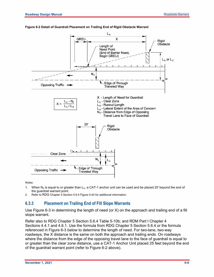
6.3.2 Placement on Trailing End of Rigid ObstacleUse Figure 6-2 to determine the length of need (or X) on the trailing end of a rigid obstacle warrant. The variables used in determining the length of need are as follows:
LA = Distance from the edge of the opposing travel lane to the area of concern. (Note diagram in Figure 6-2)
As on the approach end, use LA if LC is less than LA.
LC = Clear zone distance for the roadway. Refer to RDM Part I Chapter 4 Section 4.6.1.
N2 = Distance from edge of opposing travel lane to the face of the guardrail.
LR = Runout length. Refer to RDG Chapter 5 Section 5.6.4 Table 5-10b.On roadways where the distance from the edge of the opposing travel lane to the face of guardrail is equal to or greater than the clear zone distance, use a CAT-1 Anchor Unit placed 25 feet beyond the end of the guardrail warrant point (refer to Figure 6-2).
Roadway Design Manual Roadside Barriers
November 1, 2021 6-6
Figure 6-2 Detail of Guardrail Placement on Trailing End of Rigid Obstacle Warrant
Notes:
1. When N2 is equal to or greater than LC, a CAT-1 anchor unit can be used and be placed 25′ beyond the end of the guardrail warrant point.
2. Refer to RDG Chapter 5 Section 5.6.4 Figure 5-42 for additional information.
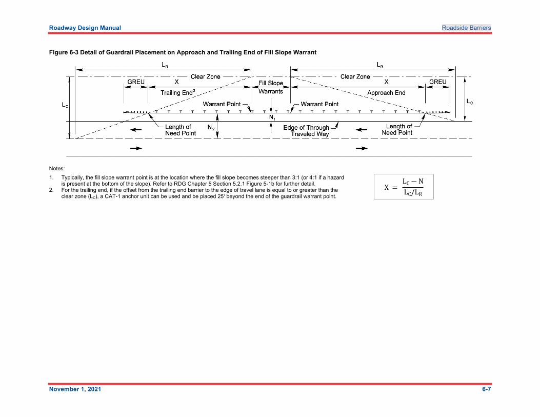
6.3.3 Placement on Trailing End of Fill Slope WarrantsUse Figure 6-3 in determining the length of need (or X) on the approach and trailing end of a fill slope warrant.Refer also to RDG Chapter 5 Section 5.6.4 Table 5-10b; and RDM Part I Chapter 4 Sections 4.4.1 and 4.6.1. Use the formula from RDG Chapter 5 Section 5.6.4 or the formula referenced in Figure 6-3 below to determine the length of need. For two-lane, two-way roadways, the X distance is the same on both the approach and trailing ends. On roadways where the distance from the edge of the opposing travel lane to the face of guardrail is equal to or greater than the clear zone distance, use a CAT-1 Anchor Unit placed 25 feet beyond the end of the guardrail warrant point (refer to Figure 6-2 above).
Roadway Design Manual Roadside Barriers
November 1, 2021 6-7
Figure 6-3 Detail of Guardrail Placement on Approach and Trailing End of Fill Slope Warrant
Notes:1. Typically, the fill slope warrant point is at the location where the fill slope becomes steeper than 3:1 (or 4:1 if a hazard
is present at the bottom of the slope). Refer to RDG Chapter 5 Section 5.2.1 Figure 5-1b for further detail.2. For the trailing end, if the offset from the trailing end barrier to the edge of travel lane is equal to or greater than the
clear zone (LC), a CAT-1 anchor unit can be used and be placed 25′ beyond the end of the guardrail warrant point.X =
LC ― NLC/LR
Roadway Design Manual Roadside Barriers
November 1, 2021 6-8
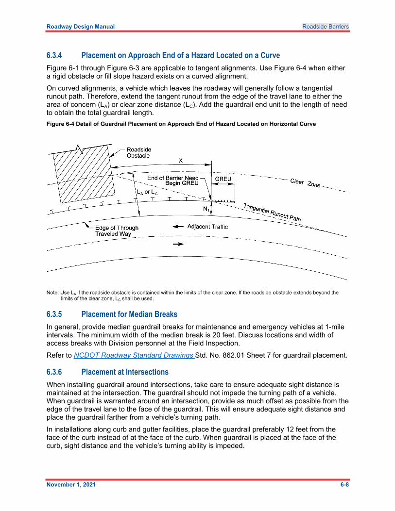
6.3.4 Placement on Approach End of a Hazard Located on a CurveFigure 6-1 through Figure 6-3 are applicable to tangent alignments. Use Figure 6-4 when either a rigid obstacle or fill slope hazard exists on a curved alignment.On curved alignments, a vehicle which leaves the roadway will generally follow a tangential runout path. Therefore, extend the tangent runout from the edge of the travel lane to either the area of concern (LA) or clear zone distance (LC). Add the guardrail end unit to the length of need to obtain the total guardrail length.Figure 6-4 Detail of Guardrail Placement on Approach End of Hazard Located on Horizontal Curve
Note: Use LA if the roadside obstacle is contained within the limits of the clear zone. If the roadside obstacle extends beyond the limits of the clear zone, LC shall be used.
6.3.5 Placement for Median BreaksIn general, provide median guardrail breaks for maintenance and emergency vehicles at 1-mile intervals. The minimum width of the median break is 20 feet. Discuss locations and width of access breaks with Division personnel at the Field Inspection. Refer to NCDOT Roadway Standard Drawings Std. No. 862.01 Sheet 7 for guardrail placement.
6.3.6 Placement at IntersectionsWhen installing guardrail around intersections, take care to ensure adequate sight distance is maintained at the intersection. The guardrail should not impede the turning path of a vehicle. When guardrail is warranted around an intersection, provide as much offset as possible from the edge of the travel lane to the face of the guardrail. This will ensure adequate sight distance and place the guardrail farther from a vehicle’s turning path.In installations along curb and gutter facilities, place the guardrail preferably 12 feet from the face of the curb instead of at the face of the curb. When guardrail is placed at the face of the curb, sight distance and the vehicle’s turning ability is impeded.
Roadway Design Manual Roadside Barriers
November 1, 2021 6-9
Refer to NCDOT Roadway Standard Drawings Std. No. 862.01, Sheet 8, for a pictorial view showing placement of guardrail at intersections.
6.3.7 Placement on -Y- Lines and Interchange BridgesConsider the addition of guardrail where warranted throughout the construction limits along a -Y- line. Remember lower speeds on the -Y- line may negate the need for guardrail.Whenever guardrail is used to shield bridge ends on -Y- lines with three or more lanes, no guardrail is warranted on the trailing end of the bridge when fill slopes are 4:1 or flatter. The elimination of the guardrail on the trailing end of the bridge will improve sight distance at ramp intersections, which are downstream of the bridge.
6.3.8 Placement Adjacent to Curb and GutterPlacement of guardrail adjacent to curb and gutter warrants careful consideration as the trajectory of the vehicle will be altered when the vehicle impacts the curb and gutter. The type of curb and gutter, vehicle speed, vehicle angle of impact, and vehicle characteristics will all influence the vehicle trajectory. Placing the guardrail flush with the face of the curb and gutter allows the guardrail to work before the vehicle trajectory is altered. Placement of the guardrail farther from the curb and gutter allows the vehicles suspension to settle the vehicle trajectory before impact with the guardrail.
Fill Height and Slope Warrant, Preferred Placement – The preferred treatment is to place the face of the guardrail 12 feet from the face of the curb. As mentioned before, the 12-foot distance allows the vehicle’s bumper to return to normal height before impacting the guardrail. The 12-foot width provides ample sight distance for any intersecting streets or driveways near the guardrail installation. This placement method also accommodates sidewalk installation. Place the guardrail behind the sidewalk.
To provide for the above installation, the berm width would have to be 14 feet. Refer to NCDOT Roadway Standard Drawings Std. No. 862.01 Sheet 11 for details on this placement.
Fill Height and Slope Warrant – When right of way restrictions prohibit the use of the preferred treatment, place the guardrail so the face of the guardrail aligns with the face of the curb. If sidewalk exists or is proposed, the sidewalk may have to be flared at the anchor unit installation. Refer to NCDOT Roadway Standard Drawings Std. No. 862.01 Sheet 11 for details on this placement.
High speed facilities frequently require a curb and guardrail combination on outside shoulders to control surface drainage and reduce erosion of fill slopes. Only use the expressway gutter and guardrail combination when the Hydraulics Unit recommends it on freeways with three or more lanes of pavement sloped in the same direction. The situation generally occurs on the low side of a superelevated curve in a fill section. Use the shoulder berm gutter and guardrail combination to meet this requirement at all other locations.Refer to RDG Chapter 3 Section 3.4.1 and Chapter 5 Section 5.6.2.1 for additional information on curb and gutter and guardrail placement.
6.3.9 Placement Under Bridges 1. With Outside Bridge Piers
a. With a Concrete Barrier
Roadway Design Manual Roadside Barriers
November 1, 2021 6-10
i. If the outside pier is 15 feet 6 inches or less from the edge of the main travel lane, use a concrete barrier and guardrail NCDOT Roadway Standard Drawings Std. No. 857.01.
ii. Extend the guardrail from the concrete barrier according to the length of need requirements as outlined in Section 6.2.2 above.
b. Without a Concrete Barrieri. If the face of the bridge pier is greater than 15 feet 6 inches from the edge of
the main travel lane but within the clear zone, use guardrail to protect the pier. The face of the guardrail will normally be placed 5 feet 6 inches from the face of pier, but usually no less than 12 feet from the edge of the main travel lane. Refer to NCDOT Roadway Standard Drawings Std. No. 862.01, Sheet 1.
ii. Extend the guardrail based on the length of need requirements as outlined in Section 6.2.2 above.
2. Without Outside Bridge Piersa. Approach with a Natural or False Cut
i. No guardrail is needed if the 6-foot vertical curve is used with NCDOT Roadway Standard Drawings Std. Nos. 225.07 and 610.03.
b. Approach in a Fill without a False Cuti. Guardrail is normally placed 6 feet to 12 feet from the edge of a local,
collector, or auxiliary lane, and 12 feet to 20 feet from the edge of a main travel lane. Guardrail spacing at the end bent slope will typically be 6 feet 3 inches. Extend the guardrail based on the length of need requirements as outlined in Section 6.2.2 above.
3. With Curb and Guttera. Review curb and gutter facilities to determine if protection of bridge piers is
required. Place the guardrail so the face of the guardrail aligns with the face of the curb.
6.3.10 Placement on Proposed Structures/CulvertsRefer to RDM Part I Chapter 5 for additional information on guardrail end units on structures. Refer to NCDOT Roadway Standard Drawings Std. Nos. 857.01, 862.01, and 862.03.
6.3.11 Placement on Bridge ApproachesPlace the guardrail at the back of the sidewalk so that it ties directly into the bridge rail as shown on NCDOT Roadway Standard Drawings Std. No. 862.01 Sheet 4.Coordinate with the Structures Management Unit to determine the type of bridge rail to be used. Typically, a Type III Guardrail End Unit to anchor the guardrail to the end of all bridges with sidewalk. Refer to NCDOT Roadway Standard Drawings Std. No. 862.03, Sheet 2.
Roadway Design Manual Roadside Barriers
November 1, 2021 6-11
6.3.12 Placement on Existing StructuresCoordinate guardrail attachments required at existing bridges with the Structure Design Lead assigned to the project. If the project has not been assigned to a Structure Design Lead, coordinate with the Structures Management Field Operations Project Engineer.The Structures Management Unit Design Manual contains examples of guardrail attachment used on previous projects; see Figures 6-32, 33, 34 and 35. If a required detail is not in the manual, the Structure Design Lead will prepare the detail and the finalized detail will be sent to the Engineering Development Section in the Structure Design Unit for distribution. At times, measurements from the Bridge Maintenance Unit will be necessary before the details can be finalized.Note: The Structure Design Lead is responsible for determining the appropriate design detail to be used or if a new design is required.
6.3.13 Temporary Guardrail PlacementDuring construction, maintain the clear zone and recovery area in accordance with the RDG. If this cannot be achieved and the hazardous situation will be temporary, protect the area with temporary guardrail or temporary concrete median barrier. Note that guardrail should be lapped in the direction of traffic. If the direction of traffic changes, the guardrail will need to be re-lapped in the new direction.For a two-way road, add a 2-foot width to the shoulder for clear roadway width and an additional 2-foot width for placement of the guardrail.In areas where guardrail or median barrier is placed in close proximity to the travel lane, take special care to avoid creating an unpaved drop-off area between the edge of the paved shoulder and the face of the barrier or guardrail.
6.4 Concrete BarriersDue to its low cost, high durability, and effective performance, concrete barrier is the most common type of rigid barrier in use today. Concrete barriers vary in size, shape, and construction type. Depending on the location and use, concrete barriers can be cast in place, slip-formed, or precast. Common concrete barrier shapes are the New Jersey, single faced, and double faced. Refer to NCDOT Roadway Standard Drawings Std. Nos. 854.01, 854.02, 854.04, 854.05 and 857.01 for examples of these shapes.Use “T” Type Double Faced Concrete Barrier (Std. No. 854.02) on all interstates and freeways with truck traffic exceeding 250 DDHV. Refer to RDG Chapter 5 Section 5.4.1.12 and RDG Chapter 6 Section 6.4.1.8 for more details on concrete barriers.
6.4.1 Positively Anchored Temporary Precast Concrete Bridge Barrier – Type SDuring staged construction, widening, or specific rehabilitation projects, the Work Zone Traffic Control Engineer may require a temporary bridge rail. In general, the pay item for temporary bridge barrier will be a traffic control item. Close coordination between the Structures Lead, roadway designer, and Work Zone Traffic Control Engineer is extremely important.
Roadway Design Manual Roadside Barriers
November 1, 2021 6-12
Adhere to the following procedures:1. The Structures Lead will contact the roadway designer and the Work Zone Traffic
Control Engineer to determine the width of the bridge deck needed to maintain traffic during construction. This will determine the location of the temporary barrier. The offset distance shall be the distance from the back of the barrier to the edge of the slab.
2. If the offset distance is from 0 feet to 3 feet 11 inches, anchor the Type S barrier positively to the slab. The roadway designer will include the detail of the Type S barrier in their plans. This barrier will be a Traffic Control pay item. The Work Zone Traffic Control Engineer will be responsible for determining pay limits and estimating pay item quantities for the Engineer’s estimate. The structure designer will include a sketch of the Type S barrier with the offset distance dimensioned and a note to see the Traffic Management plans for location and pay items of the positively anchored temporary pre-cast concrete bridge barrier - Type S.a. The Structure Design Project Group Engineer will furnish the beginning and
ending approach slab stations to the Work Zone Traffic Control Engineer and the roadway designer.
3. If the offset distance is from 4 feet to 5 feet 11 inches, use the standard precast temporary concrete median barrier found in NCDOT Roadway Standard Drawings Std. No. 1170.01.a. The structure designer will furnish the beginning and ending approach slab
stations to the Work Zone Traffic Control Engineer and the roadway designer. This will be used to determine the pay limits for the barrier. The Work Zone Traffic Control Engineer will put the following note in their plans.i. THE TEMPORARY PRECAST MEDIAN BARRIER ON THE BRIDGE
SHALL BE RESTRAINED AGAINST LATERAL MOVEMENT BY THE ANGLE AND ANCHOR SYSTEM. SEE THE BRIDGE PLANS FOR DETAIL AND PAYMENT FOR THE ANGLE AND ANCHOR SYSTEM.
4. If the offset distance is 6 feet or greater, use the standard precast temporary concrete median barrier found in NCDOT Roadway Standard Drawings Std. No. 1170.01. No attachment to the bridge deck is required. This will be a Traffic Control pay item.
5. If a bridge member is over stressed due to the use of the barrier specified in procedures 1, 2, or 3, the Structure Design Project Group Engineer will coordinate with Work Zone Traffic Control Engineer and roadway designer to use an alternate type of rail.
6.5 Cable BarriersCable barrier, or cable guiderail, is a roadside barrier that consists of steel cable mounted on weak posts. The primary use of cable barrier is placement in highway medians to prevent head-on collisions. There are two types of cable barrier systems: low-tension and high tension. Though each system has advantages and disadvantages, in general, a high-tension system has lower long-term maintenance costs but a higher initial cost. Only approved cable barrier systems are allowed on NCDOT projects.For information on cable guiderail details and placement, see NCDOT Roadway Standard Drawings Std. No.865.01 Section 4.10.8 Median Barrier Selection.
Roadway Design Manual Roadside Barriers
November 1, 2021 6-13
6.6 Safety vs. Cost GuidanceThe installation of roadside safety devices requires weighing the cost of the installation and maintenance of the safety device against the risk of injury or death of the motorist.Perform a benefit cost analysis as part of the final safety barrier determination.For more information on this subject see NCHRP Report 492 – Roadside Safety Analysis Program (RSAP)- Engineers Manual.
6.7 Guardrail and Guiderail SummariesThe guardrail summary provides details on guardrail placement and guardrail quantities. Place a guardrail summary in all plan sets for projects where guardrail is used. Note that a guardrail summary is also used for concrete barrier and temporary guardrail locations. A separate summary is usually provided for cable guiderail. For more information on the details provided in these summaries see Part II, Chapter 3 Section 3.7.1.2.
6.8 Median Barrier SelectionDepending on the situation, steel beam guardrail, cable barrier, or concrete barrier may be used in the median to protect motorists from rigid obstacles, bridge abutments, errant vehicles crossing the median or other obstacles that present a hazard to the motorist. This determination is based on the following conditions:
Median width
Bridge abutments
Existing conditions
NCDOT Division preferenceNCDOT requires median guardrail, guiderail, or barrier on all interstate and freeway projects with median widths of 70 feet or less.
6.8.1 Guidelines for Typical Median Guardrail or Guiderail Installation
6.8.1.1 Types of installations to be used Use low tension cable guiderail (LTCG) or steel beam guardrail with post spacing (semi-rigid guardrail) of 6 feet 3 inches when slopes of 6:1 or flatter exist in the median. LTCG deflects up to 12 feet. When using cable guiderail, the designer will verify the deflection of the rail does not extend into the opposing travel lane. High tension cable guiderail systems (HTCG) have lower deflections (5 feet 8 inches) than LTCG systems. Use HTCG in areas where lower deflections are needed in the median or on the outside shoulder. HTCG systems are proprietary. HTCG systems must be on the NCDOT Approved Products List and may be used at the approval of Division personnel or the State Roadway Design Engineer. Install all HTCG systems per the manufacturer’s instructions. Gibraltar, Safence, and Brifen are MASH approved HTCG systems available for use by NCDOT.Steel beam guardrail must be placed on 10:1 or flatter slopes. Steel beam guardrail with post spacing of 6 feet 3 inches normally deflects 3 feet. When using steel beam guardrail to protect from rigid obstacles, ensure the face of the guardrail is placed 5 feet 6 inches from the face of
Roadway Design Manual Roadside Barriers
November 1, 2021 6-14
the hazard. Refer to offset distance note on NCDOT Roadway Standard Drawings Std. No. 862.01, Sheet 1. Use weak post steel beam guardrail in freeway medians that have adjoining segments of weak post guardrail in place at each end of the project. Currently, NCDOT is not proposing to use weak post guardrail in any other locations. This guardrail is flexible and has post spacing of 12 feet 6 inches. The normal deflection of this guardrail is 7 feet. Weak post guardrail must be placed on slopes 10:1 or flatter. Place the guardrail as far from the edge of the travel lane as the above guidelines will allow.
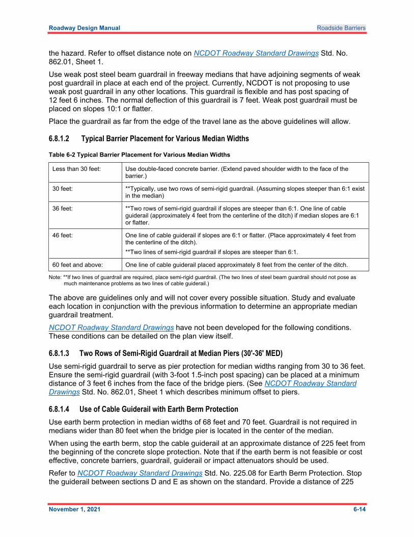
6.8.1.2 Typical Barrier Placement for Various Median Widths
Table 6-2 Typical Barrier Placement for Various Median Widths
Less than 30 feet: Use double-faced concrete barrier. (Extend paved shoulder width to the face of the barrier.)
30 feet: **Typically, use two rows of semi-rigid guardrail. (Assuming slopes steeper than 6:1 exist in the median)
36 feet: **Two rows of semi-rigid guardrail if slopes are steeper than 6:1. One line of cable guiderail (approximately 4 feet from the centerline of the ditch) if median slopes are 6:1 or flatter.
46 feet: One line of cable guiderail if slopes are 6:1 or flatter. (Place approximately 4 feet from the centerline of the ditch).**Two lines of semi-rigid guardrail if slopes are steeper than 6:1.
60 feet and above: One line of cable guiderail placed approximately 8 feet from the center of the ditch.
Note: **If two lines of guardrail are required, place semi-rigid guardrail. (The two lines of steel beam guardrail should not pose as much maintenance problems as two lines of cable guiderail.)
The above are guidelines only and will not cover every possible situation. Study and evaluate each location in conjunction with the previous information to determine an appropriate median guardrail treatment. NCDOT Roadway Standard Drawings have not been developed for the following conditions. These conditions can be detailed on the plan view itself.
6.8.1.3 Two Rows of Semi-Rigid Guardrail at Median Piers (30′-36′ MED)Use semi-rigid guardrail to serve as pier protection for median widths ranging from 30 to 36 feet. Ensure the semi-rigid guardrail (with 3-foot 1.5-inch post spacing) can be placed at a minimum distance of 3 feet 6 inches from the face of the bridge piers. (See NCDOT Roadway Standard Drawings Std. No. 862.01, Sheet 1 which describes minimum offset to piers.
6.8.1.4 Use of Cable Guiderail with Earth Berm ProtectionUse earth berm protection in median widths of 68 feet and 70 feet. Guardrail is not required in medians wider than 80 feet when the bridge pier is located in the center of the median. When using the earth berm, stop the cable guiderail at an approximate distance of 225 feet from the beginning of the concrete slope protection. Note that if the earth berm is not feasible or cost effective, concrete barriers, guardrail, guiderail or impact attenuators should be used.Refer to NCDOT Roadway Standard Drawings Std. No. 225.08 for Earth Berm Protection. Stop the guiderail between sections D and E as shown on the standard. Provide a distance of 225
Roadway Design Manual Roadside Barriers
November 1, 2021 6-15
feet from the concrete slope protection as calculated from NCDOT Roadway Standard Drawings Std. No. 225.08.
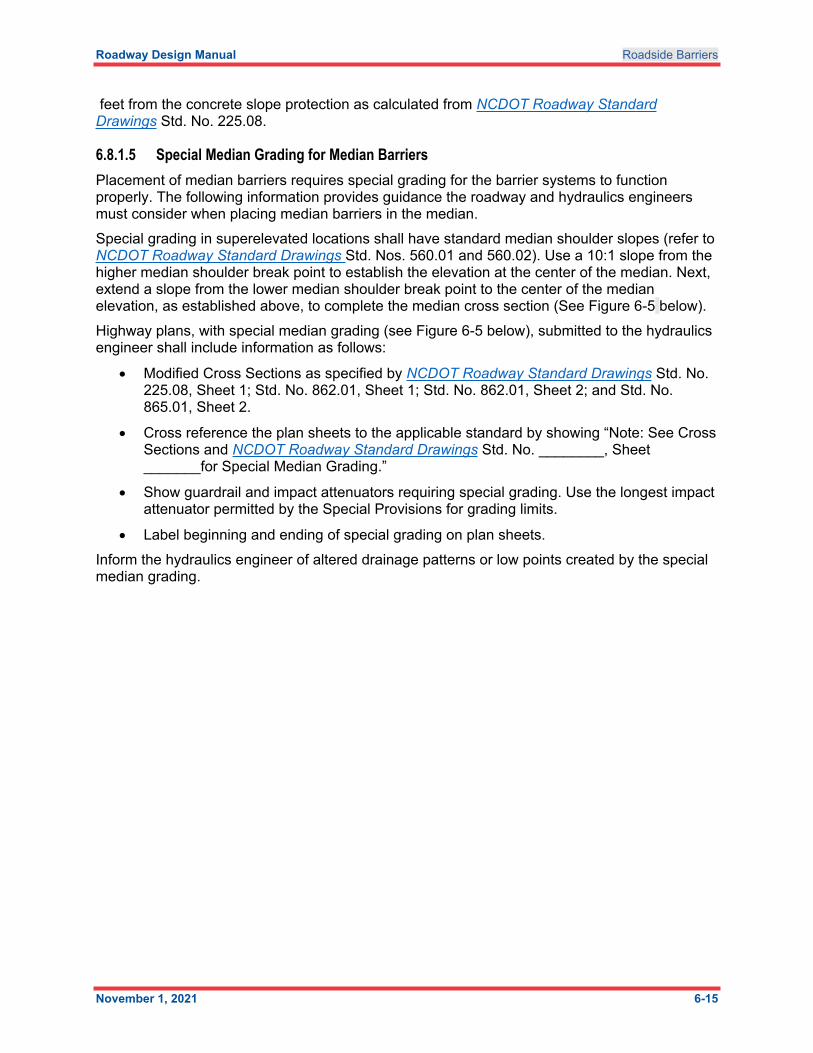
6.8.1.5 Special Median Grading for Median BarriersPlacement of median barriers requires special grading for the barrier systems to function properly. The following information provides guidance the roadway and hydraulics engineers must consider when placing median barriers in the median. Special grading in superelevated locations shall have standard median shoulder slopes (refer to NCDOT Roadway Standard Drawings Std. Nos. 560.01 and 560.02). Use a 10:1 slope from the higher median shoulder break point to establish the elevation at the center of the median. Next, extend a slope from the lower median shoulder break point to the center of the median elevation, as established above, to complete the median cross section (See Figure 6-5 below).Highway plans, with special median grading (see Figure 6-5 below), submitted to the hydraulics engineer shall include information as follows:
Modified Cross Sections as specified by NCDOT Roadway Standard Drawings Std. No. 225.08, Sheet 1; Std. No. 862.01, Sheet 1; Std. No. 862.01, Sheet 2; and Std. No. 865.01, Sheet 2.
Cross reference the plan sheets to the applicable standard by showing “Note: See Cross Sections and NCDOT Roadway Standard Drawings Std. No. ________, Sheet _______for Special Median Grading.”
Show guardrail and impact attenuators requiring special grading. Use the longest impact attenuator permitted by the Special Provisions for grading limits.
Label beginning and ending of special grading on plan sheets. Inform the hydraulics engineer of altered drainage patterns or low points created by the special median grading.
Roadway Design Manual Roadside Barriers
November 1, 2021 6-16
Figure 6-5 Special Grading in Superelevated Location
Notes: 1. () = Median shoulder width.2. See NCDOT Roadway Standard Drawings Std. No. 560.01 and 560.02 for method of shoulder construction.
Note that this special grading in superelevated location (Figure 6-5) will apply to locations that do not require traffic barriers.
Roadway Design Manual Roadside Barriers
November 1, 2021 6-17
RDG Chapter 6 Figure 6-1 provides median width guidance on when a median barrier is recommended.NCDOT Roadway Standard Drawings Std. Nos. 854.01, 854.02, 854.04, 854.05, 857.01, 862.01 and 865.01 provide details on the proper placement of safety barriers in the median and under bridges (median and outside shoulders). Other types of concrete median barriers, such as single slope, F-shape, and flat faced, may be used as approved by the State Roadway Design Engineer. All alternative concrete median barriers must meet current AASHTO and FHWA crash testing requirements.Follow NCDOT Roadway Standard Drawings Std. Nos. 560.01 and 560.02 for special grading for medians in superelevation.Refer to RDG Chapter 6 and GB Chapter 4 Section 4.10.2.2 for more information on median barriers.
6.9 Guardrail End UnitsThe following are commonly used end units with a brief description.
Guardrail End Unit Test Level 2 and Test Level 3 (GREU-TL-2 and TL-3) – The GREU TL-2 and TL-3 are tangential end units used parallel to the travel way. Flare these units over the last 50 feet to provide a 1 -foot offset. GREU-TL-2 (25 feet long) can be used when design speeds are 44 mph or less. GREU TL-3 (50 feet long) can be used when design speeds are 45 mph or greater.
Cable Anchor Terminal: (CAT-1) – The CAT-1 end treatment is not crashworthy and should only be used at locations where there is not an opportunity to have a head-on hit within a vehicle’s clear zone. A CAT-1 unit is typically placed on the trailing end of a run of guardrail.
Anchor Terminal (AT-1) – Use of the AT-1 is limited to anchoring the shop curved guardrail at intersections which have radii between 20 feet and 75 feet.
Impact Attenuators (varies) – The impact attenuator or crash cushion is used to protect roadside objects that cannot be moved.
Gating vs. Non-gating Attenuators – Gating describes an attenuator that folds (acts like a gate) and allows the vehicle to slow down in the clear zone. These are applicable when there is sufficient clear zone for the vehicle to come to a stop. The clear recovery area on each side of the gating unit has to be a minimum of 30 feet. Use a non-gating attenuator if a clear recovery area of 30 feet is not available.
Non-gating describes an attenuator that, when impacted from the front of the system, does not allow a vehicle to pass into the clear zone. A clear zone still exists, but it is usually smaller. These types of attenuators are generally used in medians or where the full clear zone is not possible.
Structure Anchor Units:
Type III – Use this anchor unit to anchor guardrail to bridges with metal bar railing or any other rail design with a vertical concrete railing or parapet allowing the Type III attachment. See NCDOT Roadway Standard Drawings Std. No. 862.03.
Type B-77 (with rubrail) – Use this guardrail end unit to attach guardrail to concrete Jersey of F-shape barrier as illustrated in NCDOT Roadway Standard Drawings Std. No. 862.03.
Roadway Design Manual Roadside Barriers
November 1, 2021 6-18
Type B-83 – Use this end unit on existing bridges with a Jersey shape barrier and an 8-inch or higher curb on the approach slab. See NCDOT Roadway Standard Drawings Std. No. 862.03.
Refer to NCDOT Roadway Standard Drawings Std. Nos. 862.01, 862.02, 862.03 and RDG Chapters 7 and 8 for more detailed information on bridge railing and end treatments.