Embed Size (px)
Citation preview
ACCC® Conductor Installation Guidelines
Chapter 7 – Stringing and Pulling WI-750-076 Rev D Page 1 of 17
©2018 CTC Global – For use with ACCC® Conductor only.
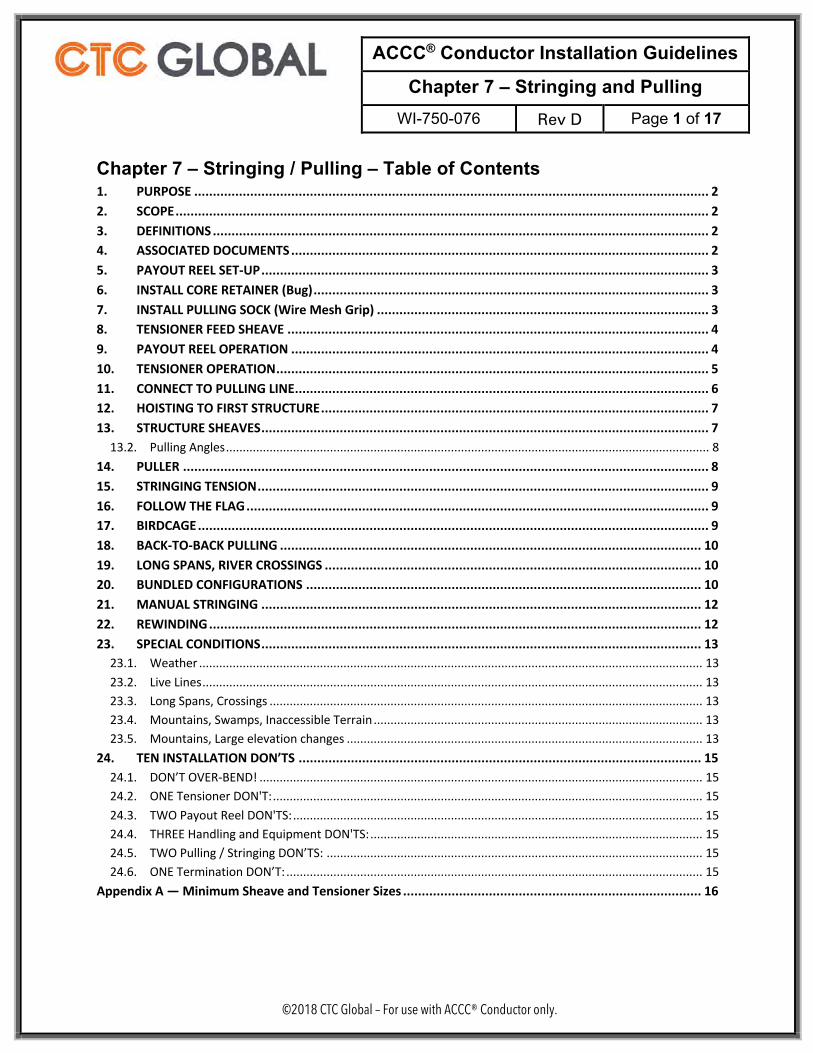
Chapter 7 – Stringing / Pulling – Table of Contents 1. PURPOSE .......................................................................................................................................... 2 2. SCOPE ............................................................................................................................................... 2 3. DEFINITIONS ..................................................................................................................................... 2 4. ASSOCIATED DOCUMENTS ................................................................................................................ 2 5. PAYOUT REEL SET-UP ........................................................................................................................ 3 6. INSTALL CORE RETAINER (Bug) .......................................................................................................... 3 7. INSTALL PULLING SOCK (Wire Mesh Grip) ......................................................................................... 3 8. TENSIONER FEED SHEAVE ................................................................................................................. 4 9. PAYOUT REEL OPERATION ................................................................................................................ 4 10. TENSIONER OPERATION .................................................................................................................... 5 11. CONNECT TO PULLING LINE ............................................................................................................... 6 12. HOISTING TO FIRST STRUCTURE ........................................................................................................ 7 13. STRUCTURE SHEAVES ........................................................................................................................ 7
13.2. Pulling Angles ................................................................................................................................................ 8 14. PULLER ............................................................................................................................................. 8 15. STRINGING TENSION ......................................................................................................................... 9 16. FOLLOW THE FLAG ............................................................................................................................ 9 17. BIRDCAGE ......................................................................................................................................... 9 18. BACK-TO-BACK PULLING ................................................................................................................. 10 19. LONG SPANS, RIVER CROSSINGS ..................................................................................................... 10 20. BUNDLED CONFIGURATIONS .......................................................................................................... 10 21. MANUAL STRINGING ...................................................................................................................... 12 22. REWINDING .................................................................................................................................... 12 23. SPECIAL CONDITIONS ...................................................................................................................... 13
23.1. Weather ...................................................................................................................................................... 13 23.2. Live Lines ..................................................................................................................................................... 13 23.3. Long Spans, Crossings ................................................................................................................................. 13 23.4. Mountains, Swamps, Inaccessible Terrain .................................................................................................. 13 23.5. Mountains, Large elevation changes .......................................................................................................... 13
24. TEN INSTALLATION DON’TS ............................................................................................................ 15 24.1. DON’T OVER-BEND! .................................................................................................................................... 15 24.2. ONE Tensioner DON'T: ................................................................................................................................ 15 24.3. TWO Payout Reel DON'TS: .......................................................................................................................... 15 24.4. THREE Handling and Equipment DON'TS: ................................................................................................... 15 24.5. TWO Pulling / Stringing DON’TS: ................................................................................................................ 15 24.6. ONE Termination DON’T: ............................................................................................................................ 15
Appendix A — Minimum Sheave and Tensioner Sizes ................................................................................ 16
ACCC® Conductor Installation Guidelines
Chapter 7 – Stringing and Pulling WI-750-076 Rev D Page 2 of 17
©2018 CTC Global – For use with ACCC® Conductor only.
1. PURPOSE 1.1. This is Chapter 7 of the ACCC® Conductor Installation Guidelines, covering ACCC
Conductor stringing or pulling. The Guidelines consist of nine chapters, each written to stand alone to address specific installation subjects. Taken together, the chapters comprise the entire Installation Guidelines:
1.1.1. Chapter 1 — General Installation Guidelines 1.1.2. Chapter 2 — Safety 1.1.3. Chapter 3 — Training 1.1.4. Chapter 4 — Reel Handling and Storage 1.1.5. Chapter 5 — Site Considerations and Set-ups 1.1.6. Chapter 6 — Tools and Equipment 1.1.7. Chapter 7 — Stringing / Pulling 1.1.8. Chapter 8 — Terminations, Sagging, and Suspending 1.1.9. Chapter 9 — Maintenance and Repair
1.2. The purpose of the Guidelines is to provide experienced transmission engineers, project managers and planners, field inspectors, utility personnel and linemen with guidelines, considerations, and requirements necessary to safely and successfully install the ACCC composite-core bare overhead conductor and accessories. This document is an overview and guideline covering what to do but not necessarily how to do it. It is not intended to serve as a more intensive training manual or act as a substitute for proper training, required personnel skill sets, or industry experience.
2. SCOPE 2.1. These guidelines apply to equipment and techniques required to successfully install all
sizes of ACCC® Conductor. 2.2. These guidelines include additional equipment and techniques that are required for Ultra-
Low Sag (ULS) and Ultra-High Strength (AZR™) (Ice Load) ACCC® Conductor types and bundled conductor installations.
3. DEFINITIONS 3.1. ACCC® is a registered trademark of CTC Global, and is defined as Aluminum Conductor
Composite Core, stranded with Aluminum 1350-0 (where 0 stands for fully annealed) or AT3 Aluminum Zirconium alloy in trapezoidal or Z-trapezoidal wire configurations.
4. ASSOCIATED DOCUMENTS
4.1. IEEE Standard 524Ô Guide to the Installation of Overhead Transmission Line Conductors.
4.2. OSHA Electric Power Generation, Transmission, and Distribution Standards 1910.269 and 1926.950 or ISO 29.240.20 or local country equivalents.
4.3. The remaining Chapters of the Installation Guidelines
ACCC® Conductor Installation Guidelines
Chapter 7 – Stringing and Pulling WI-750-076 Rev D Page 3 of 17
©2018 CTC Global – For use with ACCC® Conductor only.
5. PAYOUT REEL SET-UP 5.1. Verify that the Payout Reel Brake is of sufficient capacity and is in good working order. 5.2. Load the reel of new ACCC Conductor into the payout reel stand. Refer to reel handling
guidelines in Chapter 3. The reel mandrel, or axle, must be sized to match the arbor holes in the reel. Use arbor spacers (bushings) if needed. The reel must turn smoothly on the mandrel to avoid jumping or bouncing of the conductor during payout.
5.3. Control the free end of the conductor when it is released from its shipping constraint. The residual energy of the coiled conductor can cause that end to whip as it tends to straighten which can cause personal injury or death, and can damage the conductor.
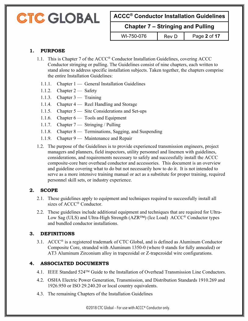
6. INSTALL CORE RETAINER (Bug) 6.1. ACCC Conductor is constructed with a smooth composite core surrounded by one or more
layers of aluminum strands. The core retainer (bug) prevents the core from slipping back inside during conductor installation so that the core is accessible for termination procedures. The bug is temporary, used only during handling and pulling/stringing.
6.2. Core Retainers are ACCC Conductor specific and supplied by CTC. Bugs may be re-used but should not be used indefinitely. Do not reuse a bug when the nut does not screw into the body easily or if the inside collet appears worn or damaged.
6.3. Detailed, step by step instructions for installing and removing bugs are included in CTC training and an instruction sheet that ships with each new bug.
6.4. Core retainers are re-usable and should be re-used unless damaged, bent, rusted, or bad threads or the inner tapered collet is not in one piece.
7. INSTALL PULLING SOCK (Wire Mesh Grip) 7.1. Wire Mesh Grips or “Socks” are used to pull in conductor. They must be correctly sized
and kept in good condition, free of rust or other contamination. Hubbell brand Kellems® K-Type Pulling Grips or Arrow Heart brand K-type Heavy Duty Pulling Grips are recommended. Pulling socks must be equipped with guarding on the wires at the eye end to prevent the conductor end strands or bug from damaging the sock wires. Do not use grips with broken or rusted wires.
7.2. Wipe the conductor free of oil, dirt or other contamination for at least the length of the sock.
7.3. The full length of the wire mesh must be fully installed on conductor or the sock will be damaged and could fail.
ACCC® Conductor Installation Guidelines
Chapter 7 – Stringing and Pulling WI-750-076 Rev D Page 4 of 17
©2018 CTC Global – For use with ACCC® Conductor only.
7.4. ALWAYS anchor the far end of the wire mesh sock. Preferred anchor method is two bands using the banding tool and appropriate banding (see Chapter 6). Alternatively, two screw-type radiator hose clamps may be used. NEVER anchor the sock anywhere except on the END furthest from the eye.
7.5. Tape the anchor. It is CRITICAL that the anchoring installed above is completely covered by plastic electrical tape to protect the lining on the blocks and assure smooth travel through blocks.
7.6. Tape between the eye and end of the sock, to prevent the core retainer (bug) from coming out of the sock and to protect the lining on the blocks and assure smooth travel through blocks.
7.7. When removing the sock after use, all of the protective tape MUST also be removed from the sock. The tape will retain moisture and cause rusting which will weaken the sock and may cause it to fail.
7.8. There may be occasions when it is necessary or desirable to pull a long (single) span with a deadend attached. Never pull a deadend through a sheave. Always be very careful of creating sharp angles in the conductor where it exits the deadend.
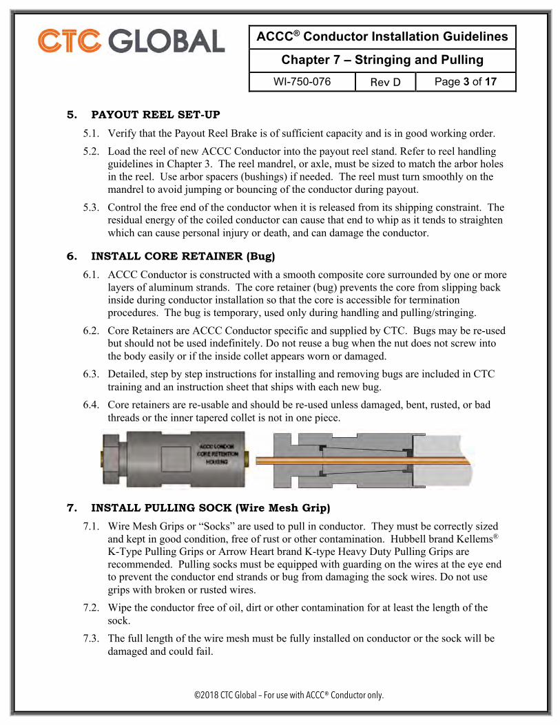
8. TENSIONER FEED SHEAVE 8.1. ALWAYS install a minimum working diameter sheave between the payout reel and the
tensioner. Position the sheave to guide the conductor into the CENTER of the tensioner fairlead. The purpose of the feed sheave is to prevent the conductor from bending sharply at any of the tensioner fairlead rollers, under any conditions.
9. PAYOUT REEL OPERATION 9.1. Payout Reel Brake. The tensioner pulls conductor from the reel and the payout reel brakes
provide light tension to keep the wraps on the payout reel tight. Never use the payout reel
X
✓
X
ACCC® Conductor Installation Guidelines
Chapter 7 – Stringing and Pulling WI-750-076 Rev D Page 5 of 17
©2018 CTC Global – For use with ACCC® Conductor only.
to assist the tensioner in supplying stringing tension. The payout reel braking system must be in good operating condition. It is NEVER acceptable to use or operate a payout reel that does not have a working brake system.
9.2. Correct operation of the payout reel brake is critical to maintain even, light tension between the reel and the tensioner. Brake tension should be set just high enough to prevent over-run when the pulling stops. Never use the payout reel brake to supply stringing tension, that is the job of the tensioner machine.
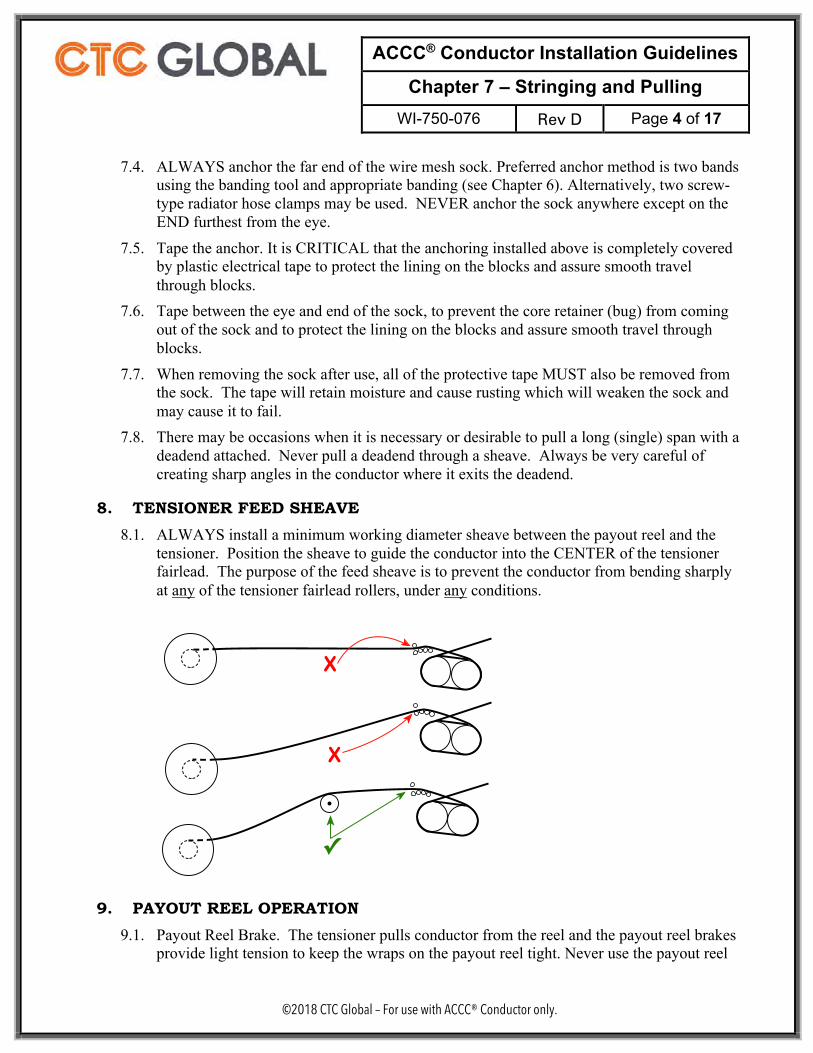
9.3. If the brake tension is too high the conductor may begin to wedge into the underlying layers on the reel which will damage the conductor and may damage the core.
9.4. As the reel empties, the moment arm available to overcome the brake drag is reduced, and
therefore the tension rises. This may cause the conductor to wedge into the underlying layers on the reel which may damage the conductor core. Hydraulic braking systems automatically avoid this condition. For other braking systems, it is important to periodically adjust the brake as the conductor is payed out.
10. TENSIONER OPERATION 10.1. Threading the Tensioner
10.1.1. The minimum bend diameter of the conductor must be respected at all times during the threading of the tensioner.
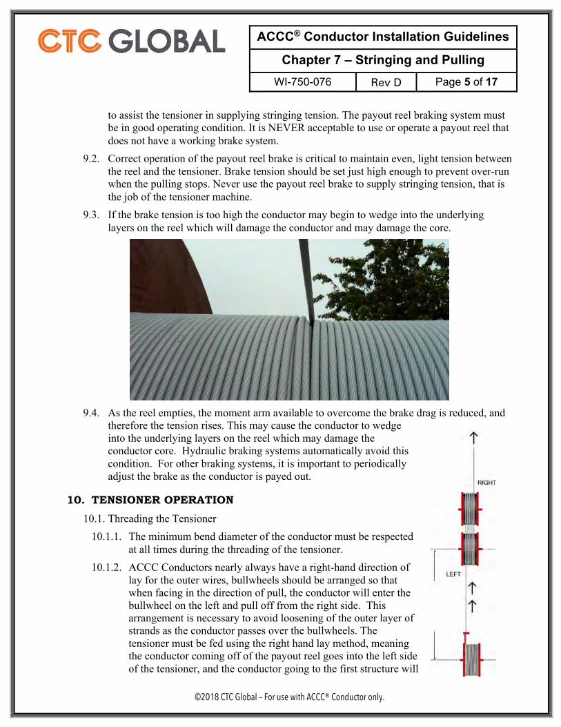
10.1.2. ACCC Conductors nearly always have a right-hand direction of lay for the outer wires, bullwheels should be arranged so that when facing in the direction of pull, the conductor will enter the bullwheel on the left and pull off from the right side. This arrangement is necessary to avoid loosening of the outer layer of strands as the conductor passes over the bullwheels. The tensioner must be fed using the right hand lay method, meaning the conductor coming off of the payout reel goes into the left side of the tensioner, and the conductor going to the first structure will
ACCC® Conductor Installation Guidelines
Chapter 7 – Stringing and Pulling WI-750-076 Rev D Page 6 of 17
©2018 CTC Global – For use with ACCC® Conductor only.
be coming out of the right side of the tensioner. If conductor is left hand lay, this is reversed.
10.1.3. Incorrect tensioner feed (in = right, out = left) will cause loosening of the strands on the tensioner and could result in bird-caging.
10.1.4. The material and finish of the grooves must be maintained properly so it will not damage the surface of the conductor. Lined grooves are recommended for all conductors, but are particularly important for non-specular finished conductors. Groove material must be relatively hard. Soft groove material will promote loosening of strands and birdcaging as it proceeds through the bull wheels. When a semi-conducting elastomer is used for lining the grooves, it must not be relied upon for grounding.
10.1.5. The tensioner should be threaded with conductor using a rope around the bull wheels. Install a core retainer (bug) on the conductor per Section 6, install the pulling sock per Section 7 and attach the sock to an approved swivel. The swivel is then attached to the rope. The rope then pulls the conductor through the tensioner bull wheels. See Section 11 below.
10.2. As the puller advances conductor through the pull, it is the tensioner which controls the tension on the pull and the sag or “bellies” in the spans of the pull.
10.3. Constant, open, priority communication between puller operation and tensioner operation is required to coordinate stops, starts, and speed of the pull.
10.4. Tensioner and puller operation is critical and must be accomplished by experienced operators, familiar with all of the controls of the tensioner and the puller.
10.5. Never use the tensioner “emergency” stop function for normal stoppages in the pulling process. The sudden emergency stop can over-tension the conductor.
10.6. Synchronized Tensioner-Payout Reel Stand Operation. 10.6.1. Tensioner / Payout Reel Stand equipment may be equipped with hydraulic
synchronization. Synchronized operation is strongly preferred for ACCC installation. In this case, the tensioner operator also operates the braking functions of the payout reel and is responsible for smooth operation of the payout reel as above. It is critical that the tensioner operator takes out the belly of the conductor between the reel and the tensioner before the pull begins.
11. CONNECT TO PULLING LINE 11.1. Old conductor may be used to pull in new ACCC Conductor ONLY if the old conductor is
entirely free of splices and damage. Splices or old conductor damage can damage sheave surfaces, which can then transfer that damage to the surface of the new ACCC. Splices or damage can hang up in sheaves, creating violent bouncing which can damage the new conductor or cause pulling equipment to fail and drop the conductor.
11.2. Connect the pulling line to the new ACCC Conductor pulling sock with a swivel of sufficient capacity and in good working order.
ACCC® Conductor Installation Guidelines
Chapter 7 – Stringing and Pulling WI-750-076 Rev D Page 7 of 17
©2018 CTC Global – For use with ACCC® Conductor only.
11.3. If the old conductor has ANY splices, they must first be cut out and replaced with two socks (wire mesh grips) connected with a swivel or a double sock.
11.4. If the old conductor has is rusted or has broken strands, then a pulling (pilot wire) line must be used. The condition of static wire may be used to help evaluate the condition of the existing conductor.
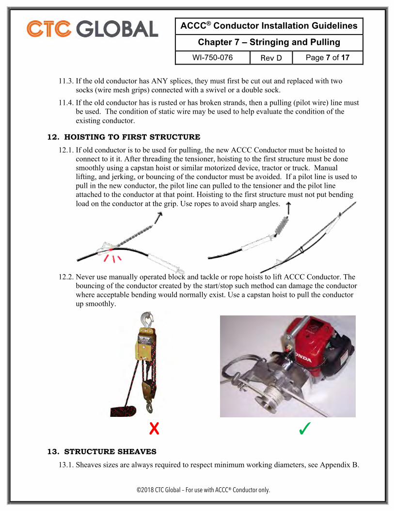
12. HOISTING TO FIRST STRUCTURE 12.1. If old conductor is to be used for pulling, the new ACCC Conductor must be hoisted to
connect to it it. After threading the tensioner, hoisting to the first structure must be done smoothly using a capstan hoist or similar motorized device, tractor or truck. Manual lifting, and jerking, or bouncing of the conductor must be avoided. If a pilot line is used to pull in the new conductor, the pilot line can pulled to the tensioner and the pilot line attached to the conductor at that point. Hoisting to the first structure must not put bending load on the conductor at the grip. Use ropes to avoid sharp angles.
12.2. Never use manually operated block and tackle or rope hoists to lift ACCC Conductor. The bouncing of the conductor created by the start/stop such method can damage the conductor where acceptable bending would normally exist. Use a capstan hoist to pull the conductor up smoothly.
X ✓
13. STRUCTURE SHEAVES 13.1. Sheaves sizes are always required to respect minimum working diameters, see Appendix B.
ACCC® Conductor Installation Guidelines
Chapter 7 – Stringing and Pulling WI-750-076 Rev D Page 8 of 17
©2018 CTC Global – For use with ACCC® Conductor only.
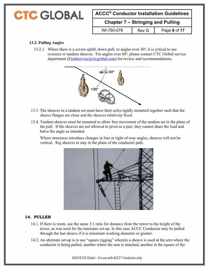
13.2. Pulling Angles 13.2.1. Where there is a severe uplift, down pull, or angles over 30º, it is critical to use
oversize or tandem sheaves. For angles over 60º, please contact CTC Global service department ([email protected]) for review and recommendations.
13.3. The sheaves in a tandem set must have their axles rigidly mounted together such that the
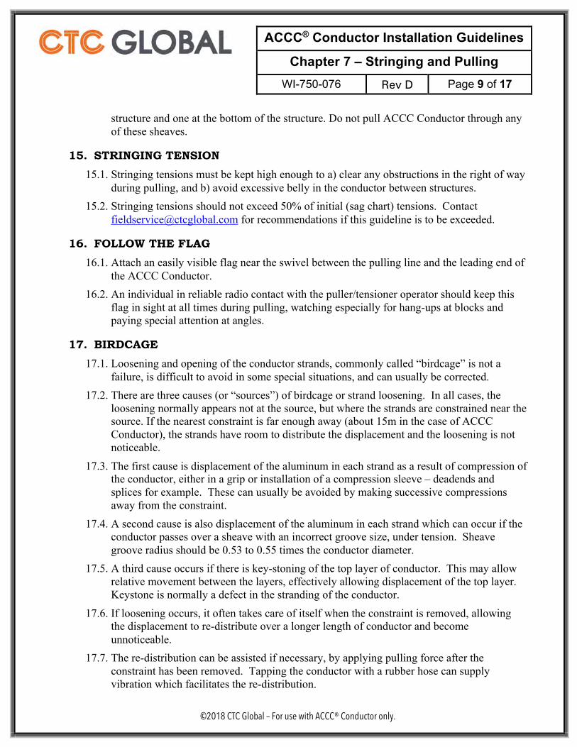
sheave flanges are close and the sheaves relatively fixed. 13.4. Tandem sheaves must be mounted to allow free movement of the tandem set in the plane of
the pull. If the sheaves are not allowed to pivot as a pair, they cannot share the load and halve the angle as intended. Where structures introduce changes in line or right-of-way angles, sheaves will not be vertical. Rig sheaves to stay in the plane of the conductor path.
14. PULLER 14.1. If there is room, use the same 3:1 ratio for distance from the tower to the height of the
tower, as was used for the tensioner set-up. In this case ACCC Conductor may be pulled through the last sheave if it is minimum working diameter or greater.
14.2. An alternate set-up is to use “square rigging” wherein a sheave is used at the arm where the conductor is being pulled, another where the arm is attached, another at the square of the
ACCC® Conductor Installation Guidelines
Chapter 7 – Stringing and Pulling WI-750-076 Rev D Page 9 of 17
©2018 CTC Global – For use with ACCC® Conductor only.
structure and one at the bottom of the structure. Do not pull ACCC Conductor through any of these sheaves.
15. STRINGING TENSION 15.1. Stringing tensions must be kept high enough to a) clear any obstructions in the right of way
during pulling, and b) avoid excessive belly in the conductor between structures. 15.2. Stringing tensions should not exceed 50% of initial (sag chart) tensions. Contact
[email protected] for recommendations if this guideline is to be exceeded.
16. FOLLOW THE FLAG 16.1. Attach an easily visible flag near the swivel between the pulling line and the leading end of
the ACCC Conductor. 16.2. An individual in reliable radio contact with the puller/tensioner operator should keep this
flag in sight at all times during pulling, watching especially for hang-ups at blocks and paying special attention at angles.
17. BIRDCAGE 17.1. Loosening and opening of the conductor strands, commonly called “birdcage” is not a
failure, is difficult to avoid in some special situations, and can usually be corrected. 17.2. There are three causes (or “sources”) of birdcage or strand loosening. In all cases, the
loosening normally appears not at the source, but where the strands are constrained near the source. If the nearest constraint is far enough away (about 15m in the case of ACCC Conductor), the strands have room to distribute the displacement and the loosening is not noticeable.
17.3. The first cause is displacement of the aluminum in each strand as a result of compression of the conductor, either in a grip or installation of a compression sleeve – deadends and splices for example. These can usually be avoided by making successive compressions away from the constraint.
17.4. A second cause is also displacement of the aluminum in each strand which can occur if the conductor passes over a sheave with an incorrect groove size, under tension. Sheave groove radius should be 0.53 to 0.55 times the conductor diameter.
17.5. A third cause occurs if there is key-stoning of the top layer of conductor. This may allow relative movement between the layers, effectively allowing displacement of the top layer. Keystone is normally a defect in the stranding of the conductor.
17.6. If loosening occurs, it often takes care of itself when the constraint is removed, allowing the displacement to re-distribute over a longer length of conductor and become unnoticeable.
17.7. The re-distribution can be assisted if necessary, by applying pulling force after the constraint has been removed. Tapping the conductor with a rubber hose can supply vibration which facilitates the re-distribution.
ACCC® Conductor Installation Guidelines
Chapter 7 – Stringing and Pulling WI-750-076 Rev D Page 10 of 17
©2018 CTC Global – For use with ACCC® Conductor only.
17.8. Never strike the conductor with wood or hammer in an effort to address a bird cage condition. Never attempt to realign strands with screwdriver or other tools.
17.9. Extreme birdcage, when the loosening causes severe plastic deformation of the strands, cannot be corrected and must be replaced.
18. BACK-TO-BACK PULLING 18.1. Reels of ACCC Conductor may be pulled back-to-back for a variety of reasons including to
avoid difficult setup areas. Two reels may be pulled back to back and up to maximum three reels if the site conditions don’t allow proper access. As a guideline, pulls should not be more than 20 spans.
18.2. Back-to-Back pulls require higher pulling tensions. Double check equipment load ratings and condition of wire mesh (sock) grips used for back-to-back reel pulls. NEW tension bearing equipment is recommended for back-to-back pulls.
18.3. Back-to-Back pulls must always be joined by two socks (wire mesh grips), with core retainers (bugs) on each ACCC end, joined by a swivel. Splices must be installed after the conductor is in place or pulled through the last relevant sheave. Splices must never be pulled through sheaves.
18.4. Core retainers (bugs) must be installed for each sock grip. 18.5. Swivels must be used between reels. Special attention should be paid to the capacity and
condition of swivels. 18.6. When multiple reels are pulled to extend sections, splices are normally installed only after
the conductor has been pulled into position. ACCC Conductor splices must never be allowed to run through sheaves, unless specialized splices and procedures are certified to facilitate safe, reliable installation.
19. LONG SPANS, RIVER CROSSINGS 19.1. Long pulls require higher pulling tensions. Double check equipment load ratings. Use only
NEW wire mesh (Kellum) (sock) grips on the ACCC Conductor for long, critical pulls. Use only NEW or new condition swivels and hardware.
19.2. When re-conductoring long spans, a pilot wire must be used to pull the ACCC Conductor. Do not pull ACCC in with the old wire.
19.3. When tall structures combined with large belly in the conductor during the pull results in angles greater than 20°, always use tandem sheave blocks. When angles greater than 30° are expected, special multiple-sheave blocks may be required; please consult with CTC Service ([email protected]).
19.4. Temporary guys or support for towers or arms may be necessary to compensate for the additional weight and tension applied to structures during long pulls.
20. BUNDLED CONFIGURATIONS
ACCC® Conductor Installation Guidelines
Chapter 7 – Stringing and Pulling WI-750-076 Rev D Page 11 of 17
©2018 CTC Global – For use with ACCC® Conductor only.
20.1. When line design calls for multiple conductors per phase, additional considerations for stringing and pulling are required.
20.2. All of the guidelines for single conductor pulling apply to bundled pulling. This section identifies additional concerns, requirement, and special equipment.
20.3. All conductors in the phase bundle may be pulled in simultaneously using a single pilot line. Because the cost of pulling line failure is multiplied by the number of conductors, new pilot line is required. Size the pilot line for the cumulative loads of the individual conductors and remember to add 2% to the total pulling tension for each structure.
20.4. If sub-conductors in a bundle must be pulled in separately, or in groups less than the entire bundle, the “alternate” sagging procedures (Chapter 8, Section 9.5) must be used.
20.5. Site considerations and set-ups have additional consideration for bundled applications. See Chapter 5.
20.6. Pulling multiple conductors simultaneously requires some specialized equipment. See Chapter 6.
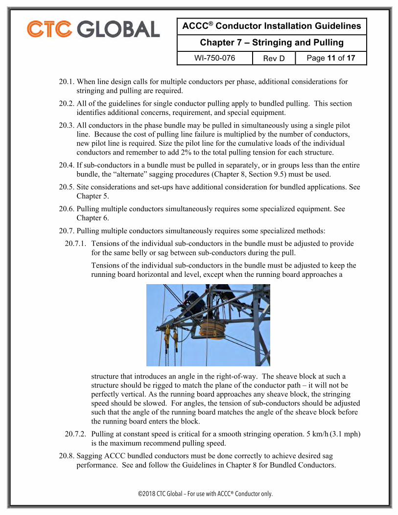
20.7. Pulling multiple conductors simultaneously requires some specialized methods: 20.7.1. Tensions of the individual sub-conductors in the bundle must be adjusted to provide
for the same belly or sag between sub-conductors during the pull. Tensions of the individual sub-conductors in the bundle must be adjusted to keep the running board horizontal and level, except when the running board approaches a
structure that introduces an angle in the right-of-way. The sheave block at such a structure should be rigged to match the plane of the conductor path – it will not be perfectly vertical. As the running board approaches any sheave block, the stringing speed should be slowed. For angles, the tension of sub-conductors should be adjusted such that the angle of the running board matches the angle of the sheave block before the running board enters the block.
20.7.2. Pulling at constant speed is critical for a smooth stringing operation. 5 km/h (3.1 mph) is the maximum recommend pulling speed.
20.8. Sagging ACCC bundled conductors must be done correctly to achieve desired sag performance. See and follow the Guidelines in Chapter 8 for Bundled Conductors.
ACCC® Conductor Installation Guidelines
Chapter 7 – Stringing and Pulling WI-750-076 Rev D Page 12 of 17
©2018 CTC Global – For use with ACCC® Conductor only.
21. MANUAL STRINGING 21.1. In special situations, especially when re-conductoring, the use of powered pulling
equipment (pullers and/or tensioners) may not be possible. In these cases, manual stringing of ACCC Conductor may be required. Layout Method (fixed reel) or Slack Method (moving reel) are allowed.
21.2. Keep the conductor out of the dirt. Lay the conductor on matting on the ground.
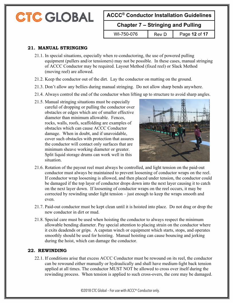
21.3. Don’t allow any bellies during manual stringing. Do not allow sharp bends anywhere. 21.4. Always control the end of the conductor when lifting up to structure to avoid sharp angles. 21.5. Manual stringing situations must be especially
careful of dropping or pulling the conductor over obstacles or edges which are of smaller effective diameter than minimum allowable. Fences, rocks, walls, roofs, scaffolding are examples of obstacles which can cause ACCC Conductor damage. When in doubt, and if unavoidable, cover such obstacles with protection that assures the conductor will contact only surfaces that are minimum sheave working diameter or greater. Split liquid storage drums can work well in this situation.
21.6. Rotation of the payout reel must always be controlled, and light tension on the paid-out conductor must always be maintained to prevent loosening of conductor wraps on the reel. If conductor wrap loosening is allowed, and then placed under tension, the conductor could be damaged if the top layer of conductor drops down into the next layer causing it to catch on the next layer down. If loosening of conductor wraps on the reel occurs, it may be corrected by rewinding under light tension – just enough to keep the wraps smooth and even.
21.7. Paid-out conductor must be kept clean until it is hoisted into place. Do not drag or drop the new conductor in dirt or mud.
21.8. Special care must be used when hoisting the conductor to always respect the minimum allowable bending diameter. Pay special attention to placing strain on the conductor where it exits deadends or grips. A capstan winch or equipment which starts, stops, and operates smoothly should be used for hoisting. Manual hoisting can cause bouncing and jerking during the hoist, which can damage the conductor.
22. REWINDING 22.1. If conditions arise that excess ACCC Conductor must be rewound on its reel, the conductor
can be rewound either manually or hydraulically and shall have medium-light back tension applied at all times. The conductor MUST NOT be allowed to cross over itself during the rewinding process. When tension is applied to such cross-overs, the core may be damaged.
ACCC® Conductor Installation Guidelines
Chapter 7 – Stringing and Pulling WI-750-076 Rev D Page 13 of 17
©2018 CTC Global – For use with ACCC® Conductor only.
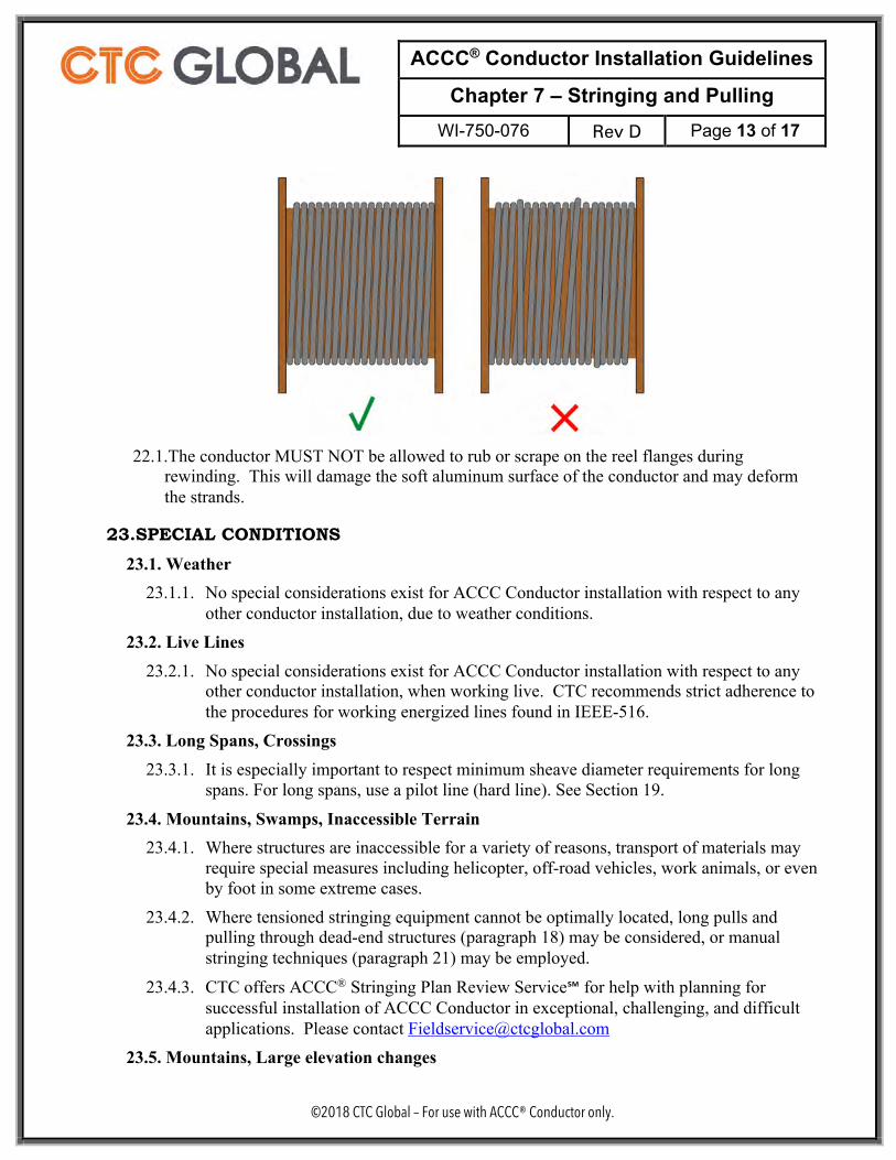
22.1. The conductor MUST NOT be allowed to rub or scrape on the reel flanges during
rewinding. This will damage the soft aluminum surface of the conductor and may deform the strands.
23. SPECIAL CONDITIONS 23.1. Weather
23.1.1. No special considerations exist for ACCC Conductor installation with respect to any other conductor installation, due to weather conditions.
23.2. Live Lines 23.2.1. No special considerations exist for ACCC Conductor installation with respect to any
other conductor installation, when working live. CTC recommends strict adherence to the procedures for working energized lines found in IEEE-516.
23.3. Long Spans, Crossings 23.3.1. It is especially important to respect minimum sheave diameter requirements for long
spans. For long spans, use a pilot line (hard line). See Section 19.
23.4. Mountains, Swamps, Inaccessible Terrain 23.4.1. Where structures are inaccessible for a variety of reasons, transport of materials may
require special measures including helicopter, off-road vehicles, work animals, or even by foot in some extreme cases.
23.4.2. Where tensioned stringing equipment cannot be optimally located, long pulls and pulling through dead-end structures (paragraph 18) may be considered, or manual stringing techniques (paragraph 21) may be employed.
23.4.3. CTC offers ACCC® Stringing Plan Review Service℠ for help with planning for successful installation of ACCC Conductor in exceptional, challenging, and difficult applications. Please contact [email protected]
23.5. Mountains, Large elevation changes
ACCC® Conductor Installation Guidelines
Chapter 7 – Stringing and Pulling WI-750-076 Rev D Page 14 of 17
©2018 CTC Global – For use with ACCC® Conductor only.
23.5.1. Where a single pull includes large elevation changes, the stringing tenstion is increased by the net weight of the conductor in the vertical change. This must be accounted for when selecting and sizing equipment and tooling. Respect equipment and tooling load ratings and use new and/or test all equipment which will be exposed to tension loads.
23.5.2. This increased stringing tension must not exceed the final sag tension or sag behaviour will be affected.
23.5.3. It is generally preferable to pull from high to low when possible because better tension control can be achieved from the tensioner machine and because tension loads on the pulling wire or line are minimized versus pulling uphill.
23.6. Please contact CTC for advice regarding special conditions not covered in the installation guidelines: [email protected]
ACCC® Conductor Installation Guidelines
Chapter 7 – Stringing and Pulling WI-750-076 Rev D Page 15 of 17
©2018 CTC Global – For use with ACCC® Conductor only.
24. TEN INSTALLATION DON’TS 24.1. DON’T OVER-BEND!
Don’t allow the conductor to contact surfaces that present sharp angles or small diameters. 24.2. ONE Tensioner DON'T:
Don’t let ACCC® Conductor run hard on the end roller of the fairlead. Always use a tensioner feed sheave between the payout reel and tensioner to guide the conductor into the middle of the tensioner fairlead opening. A multiple-roller “banana” fairlead is highly recommended.
24.3. TWO Payout Reel DON'TS: Don’t allow the conductor to bounce or jump up and down between the payout reel and the tensioner. When the conductor is jumping or bouncing, the core can be damaged. Don’t use a payout reel with insufficient brakes. Poorly maintained or undersized brakes will cause jumping and bouncing of the conductor between the payout reel and the tensioner. The payout reel brakes should allow the tensioner to draw new conductor from the reel smoothly and evenly.
24.4. THREE Handling and Equipment DON'TS: Don’t use grips that aren’t designed for installing ACCC Conductor. Use Klein “Chicago” long jaw grips or equal, designed for the size conductor being installed. Properly sized wedge type tension grips are permitted. Never use pocketbook grips! Don't allow the conductor tail or the deadend to fall or droop unsupported while handling the conductor. If the tail is not controlled, it will damage the core at the back of the grip. Don’t hoist the conductor in any manner which causes a sharp bend in the conductor.
24.5. TWO Pulling / Stringing DON’TS: Don’t install any ACCC Conductor with under-diameter sheaves on the first and last structure or any angles that are over 30 degrees. Don't pull in conductor using old conductor if it is rusty. Don’t use old conductor with splices or broken strands for pulling. Instead, pull in a pilot line using the old conductor and pull in ACCC Conductor using the pilot line. Always use a pilot line for long spans and river crossings.
24.6. ONE Termination DON’T: Don’t allow a sharp bend where the conductor exits the termination hardware. Hoisting conductor or deadend without paying attention to this area can damage the core at that point.
ACCC® Conductor Installation Guidelines
Chapter 7 – Stringing and Pulling WI-750-076 Rev D Page 16 of 17
©2018 CTC Global – For use with ACCC® Conductor only.
millimeters inches millimeters inches millimeters inchesSilvassaHelsinki
Copenhagen LinnetRovinj Oceanside
GdanskZadar
Reykjavik OrioleCasablanca Laredo
Lisbon HawkJaipur
Glasgow WacoAmsterdam Dove
Cordoba8.13 0.320 Brussels Grosbeak 710 28
Oslo IrvingStockholm LubbockWarsaw GalvestonHamburg Plano
Milan Corpus ChristiVienna CardinalPrague El PasoParis Bittern
LeipzigDublin DrakeKolkataRome Arlington
Budapest Fort WorthMumbaiMunich Beaumont (Dhaka)London San Antonio
Antwerp DallasMadrid Lapwing
ChukarChukar II
Monte Carlo25mm
WarwickCurlew
BordeauxBerlin
HoustonFalcon
Athens Bluebird
millimeters inches millimeters inches millimeters inchesULS Oslo ULS Irving
ULS WarsawULS Stockholm
ULS LubbockULS Galveston
ULS Hamburg ULS PlanoULS Milan ULS Corpus Christi
ULS PragueULS El PasoULS Bittern
ULS Vienna ULS CardinalULS Paris
ULS LeipzigULS KolkataULS Dublin ULS DrakeULS Rome ULS Arlington
ULS Budapest ULS Fort WorthULS Mumbai
ULS Beaumont (ULS Dhaka)ULS London
ULS DallasULS San Antonio
ULS AntwerpULS Madrid ULS Lapwing
ULS ChukarULS Chukar II
ULS AlgiersULS Mahakam
ULS Monte CarloULS Warwick
ULS 25mmULS Bordeaux
ULS CurlewULS Berlin ULS Houston
ULS FalconULS Athens ULS Bluebird
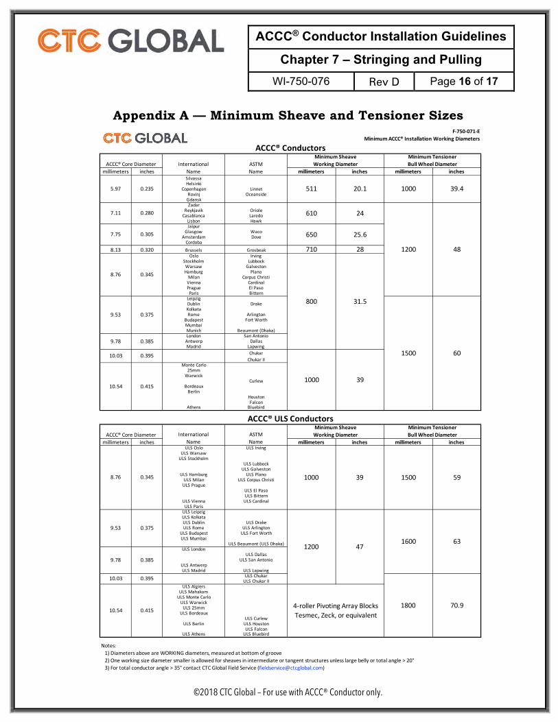
Notes:1) Diameters above are WORKING diameters, measured at bottom of groove2) One working size diameter smaller is allowed for sheaves in intermediate or tangent structures unless large belly or total angle > 20°3) For total conductor angle > 35° contact CTC Global Field Service ([email protected])
Minimum TensionerBull Wheel Diameter
1500
Minimum TensionerBull Wheel Diameter
1500
1600
1800
59
70.9
63
InternationalName
ASTMName
5.97 0.235 511 20.1
10.03 0.395 60
9.53 0.375
F-750-071-EMinimum ACCC® Installation Working Diameters
Minimum SheaveWorking Diameter
0.305
0.345
InternationalName
ASTMName
0.385
ACCC® Conductors
9.53
8.76
7.75
8.76
9.78
10.54
10.54
ACCC® Core Diameter
Minimum SheaveWorking Diameter
0.345
0.375
10.03 0.395
9.78 0.385
1000 39
ACCC® ULS Conductors
0.415
0.415
7.11 0.280
ACCC® Core Diameter
1000 39.4
1200 48
650 25.6
610 24
800 31.5
1000 39
4-roller Pivoting Array BlocksTesmec, Zeck, or equivalent
1200 47
Appendix A — Minimum Sheave and Tensioner Sizes

ACCC® Conductor Installation Guidelines
Chapter 7 – Stringing and Pulling WI-750-076 Rev D Page 17 of 17
©2018 CTC Global – For use with ACCC® Conductor only.
REVISION HISTORY
REV. CHANGE REQUEST # DATE
A 121515-1 Feb, 2016
B Updated Section 17, Back-to-Back pulling April, 2016
C
Revised graphic at 13.3 Added paragraph 13.6 Added Section 15, “Stringing Tension” Revised paragraph 18.1 Added new paragraph 18.2 Revised paragraph 18.3 Added new Section 20, “Bundled Configurations” Added paragraphs 21.2, 21.3, and 21.4 Revised paragraph 22.1 Added new Section 23 “Special Conditions” subsections: 23.3 – Long Spans and Crossing 23.4 - Mountains, Swamps, Inacessible Terrain 23.5 – Large Elevation Changes Appendix A changed from F-750-071 revision B to C
July, 2017
D
Added AZR to Section 2.2 and 3.1 Modified Title “Stringing and Pulling” was “Stringing / Pulling” Added paragraph 5.3 Moved INSTALL CORE RETAINER (BUG) to Section 6 Moved INSTALL PULLING SOCK to Section 7 Replaced “double socks” with “two socks”, Sections 11.3 and 18.3 Changed Section 18.3 “ACCC Splices” to “Splices” Section 20.3 “may” was “must” Appendix A: F-750-071-E was -C Changed footer copyright to 2018
September, 2018