Embed Size (px)
Citation preview

Chapter 7: Symmetrical Components and Representation of Faulted Networks 2013
121 Electrical Power Systems
Chapter 7: Symmetrical Components and Representation of Faulted
Networks
Overview
An unbalanced three-phase system can be resolved into three balanced systems in the sinusoidal steady state. This method of resolving an unbalanced system into three balanced phasor system has been proposed by C. L. Fortescue. This method is called resolving symmetrical components of the original phasors or simply symmetrical components. In this chapter we shall discuss symmetrical components transformation and then will present how unbalanced components like Y- or Δ -connected loads, transformers, generators and transmission lines can be resolved into symmetrical components. We can then combine all these components together to form what are called sequence networks .
Section I: Symmetrical Components
Symmetrical Component Transformation
Real and Reactive Power
Orthogonal Transformation
Symmetrical Components
A system of three unbalanced phasors can be resolved in the following three symmetrical components:
Positive Sequence: A balanced three-phase system with the same phase sequence as the original sequence.
Negative sequence: A balanced three-phase system with the opposite phase sequence as the original sequence.
Zero Sequence: Three phasors that are equal in magnitude and phase.
Fig. 7.1 depicts a set of three unbalanced phasors that are resolved into the three sequence components mentioned above. In this the original set of three phasors are denoted by Va , Vb and Vc , while their positive, negative and zero sequence components are denoted by the subscripts 1, 2 and 0 respectively. This implies that the positive, negative and zero sequence components of phase-a are denoted by Va1 , Va2 and Va0 respectively. Note that just like the voltage phasors given in Fig. 7.1 we can also resolve three unbalanced current phasors into three symmetrical components.
Fig. 7.1 Representation of (a) an unbalanced network, its (b) positive sequence, (c) negative sequence and (d) zero sequence.
Symmetrical Component Transformation

Chapter 7: Symmetrical Components and Representation of Faulted Networks 2013
122 Electrical Power Systems
Before we discuss the symmetrical component transformation, let us first define the α -operator. This has
been given in (1.34) and is reproduced below.
Note that for the above operator the following relations hold
Also note that we have
Using the a -operator we can write from Fig. 7.1 (b)
Similarly from Fig. 7.1 (c) we get
Finally from Fig. 7.1 (d) we get
Therefore,
(7.1)
(7.2)
(7.3)
(7.4)
(7.5)
(7.6)
(7.7)
(7.8)
(7.9)

Chapter 7: Symmetrical Components and Representation of Faulted Networks 2013
123 Electrical Power Systems
The symmetrical component transformation matrix is then given by
Defining the vectors V a012 and V abc as
we can write (7.4) as
where C is the symmetrical component transformation matrix and is given by
The original phasor components can be obtained from the inverse symmetrical component
transformation, i.e.,
(7.10)
(7.11)
(7.12)
(7.13)
(7.14)

Chapter 7: Symmetrical Components and Representation of Faulted Networks 2013
124 Electrical Power Systems
Finally, if we define a set of unbalanced current phasors as Iabc and their symmetrical components as Ia012
, we can then define
Example 7.1
Let us consider a set of balanced voltages given in per unit by
These imply
Then from (7.7) we get
We then see that for a balanced system the zero and negative sequence voltages are zero. Also the positive sequence voltage is the same as the original system, i.e.,
Example 7.2
All the quantities given in this example are in per unit. Let us now consider the following set of three unbalanced voltages
If we resolve them using (7.4) we then have
(7.15)

Chapter 7: Symmetrical Components and Representation of Faulted Networks 2013
125 Electrical Power Systems
Therefore we have
Furthermore note that
Real and Reactive Power
The three-phase power in the original unbalanced system is given by
where I* is the complex conjugate of the vector I . Now from (7.10) and (7.15) we get
From (7.11) we get
Therefore from (7.17) we get
We then find that the complex power is three times the summation of the complex power of the three phase sequences
(7.16)
(7.17)
(7.18)

Chapter 7: Symmetrical Components and Representation of Faulted Networks 2013
126 Electrical Power Systems
Example 7.3
Let us consider the voltages given in Example 7.2. Let us further assume that these voltages are line-to-neutral voltages and they supply a balanced Y-connected load whose per phase impedance is ZY = 0.2 + j 0.8 per unit. Then the per unit currents in the three phases are
pu
pu
pu
Then the real and reactive power consumed by the load is given by
Now using the transformation (7.15) we get
pu
From the results given in Example 7.2 and from the above values we can compute the zero sequence complex power as
pu
The positive sequence complex power is
pu
Finally the negative sequence complex power is
pu
Adding the three complex powers together we get the total complex power consumed by the load as

Chapter 7: Symmetrical Components and Representation of Faulted Networks 2013
127 Electrical Power Systems
pu
Orthogonal Transformation
Instead of the transformation matrix given in (7.13), let us instead use the transformation matrix
We then have
Note from (7.19) and (7.20) that C -1 = ( CT )* . We can therefore state C( CT )* = I3 , where I3 is (3 × 3) identity matrix. Therefore the transformation matrices given in (7.19) and (7.20) are orthogonal. Now
since
we can write from (7.17)
We shall now discuss how different elements of a power system are represented in terms of their sequence components. In fact we shall show that each element is represented by three equivalent circuits, one for each symmetrical component sequence.
Section II: Sequence Circuits for Loads
In this section we shall construct sequence circuits for both Y and Δ -connected loads separately.
Sequence Circuit for a Y-Connected Load
Sequence Circuit for a Δ-Connected Load
Sequence Circuit for a Y-Connected Load
(7.19)
(7.20)
(7.21)

Chapter 7: Symmetrical Components and Representation of Faulted Networks 2013
128 Electrical Power Systems
Consider the balanced Y-connected load that is shown in Fig. 7.2. The neutral point (n) of the windings are grounded through an impedance Zn . The load in each phase is denoted by ZY . Let us consider phase-a of the load. The voltage between line and ground is denoted by Va , the line-to-neutral voltage is
denoted by Van and voltage between the neutral and ground is denoted by Vn . The neutral current is then
Therefore there will not be any positive or negative sequence current flowing out of the neutral point.
Fig. 7.2 Schematic diagram of a balanced Y-connected load.
The voltage drop between the neutral and ground is
Now
We can write similar expression for the other two phases. We can therefore write
Pre-multiplying both sides of the above equation by the matrix C and using (7.8) we get
Now since
(7.22)
(7.23)
(7.24)
(7.25)
(7.26)

Chapter 7: Symmetrical Components and Representation of Faulted Networks 2013
129 Electrical Power Systems
We get from (7.26)
We then find that the zero, positive and negative sequence voltages only depend on their respective sequence component currents. The sequence component equivalent circuits are shown in Fig. 7.3. While the positive and negative sequence impedances are both equal to ZY , the zero sequence impedance is
equal to
If the neutral is grounded directly (i.e., Zn = 0), then Z0 = ZY . On the other hand, if the neutral is kept
floating (i.e., Zn = ∞ ), then there will not be any zero sequence current flowing in the circuit at all.
Fig. 7.3 Sequence circuits of Y-connected load: (a) positive, (b) negative and (c) zero sequence.
Sequence Circuit for a Δ -Connected Load
Consider the balanced Δ -connected load shown in Fig. 7.4 in which the load in each phase is denoted
by ZΔ . The line-to-line voltages are given by
Adding these three voltages we get
(7.27)
(7.28)
(7.29)

Chapter 7: Symmetrical Components and Representation of Faulted Networks 2013
130 Electrical Power Systems
Fig. 7.4 Schematic diagram of a balanced Δ -connected load.
Denoting the zero sequence component Vab , Vbc and Vca as Vab0 and that of Iab , Ibc and Ica as Iab0 we can
rewrite (7.30) as
Again since
We find from (7.31) Vab0 = Iab0 = 0. Hence a Δ -connected load with no mutual coupling has not any zero sequence circulating current. Note that the positive and negative sequence impedance for this load will be equal to ZΔ .
Example 7.4
Consider the circuit shown in Fig. 7.5 in which a Δ -connected load is connected in parallel with a Y-connected load. The neutral point of the Y-connected load is grounded through an impedance. Applying Kirchoff's current law at the point P in the circuit we get
The above expression can be written in terms of the vector Vabc as
Since the load is balanced we can write
(7.30)
(7.31)

Chapter 7: Symmetrical Components and Representation of Faulted Networks 2013
131 Electrical Power Systems
Fig. 7.5 Parallel connection of balanced D and Y-connected loads.
Pre-multiplying both sides of the above expression by the transformation matrix C we get
Now since
we get
Separating the three components, we can write from the above equation
Suppose now if we convert the Δ -connected load into an equivalent Y, then the composite load will be a parallel combination of two Y-connected circuits - one with an impedance of ZY and the other with an impedance of ZΔ /3. Therefore the positive and the negative sequence impedances are given by the parallel combination of these two impedances. The positive and negative sequence impedance is then given by

Chapter 7: Symmetrical Components and Representation of Faulted Networks 2013
132 Electrical Power Systems
Now refer to Fig. 7.5. The voltage Vn is given by
From Fig. 7.5 we can also write Ia = IaΔ + IaY . Therefore
This implies that Ia0 = Iay0 and hence Vn = 3Zn Ia0 . We can then rewrite the zero sequence current expression as
It can be seen that the ZΔ term is absent from the zero sequence impedance.
Section III: Sequence Circuits for Synchronous Generator
The three-phase equivalent circuit of a synchronous generator is shown in Fig. 1.16. This is redrawn in Fig. 7.6 with the neutral point grounded through a reactor with impedance Zn . The neutral current is then
given by
Fig. 7.6 Equivalent circuit of a synchronous generator with grounded neutral.
The derivation of Section 1.3 assumes balanced operation which implies Ia + Ib + Ic = 0. As per (7.32) this assumption is not valid any more. Therefore with respect to this figure we can write for phase-a voltage as
(7.32)
Chapter 7: Symmetrical Components and Representation of Faulted Networks 2013
133 Electrical Power Systems
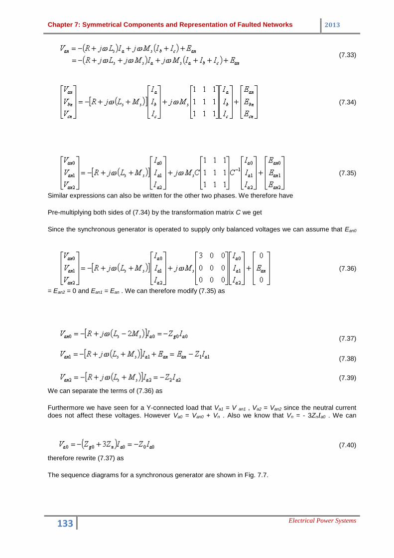
Similar expressions can also be written for the other two phases. We therefore have
Pre-multiplying both sides of (7.34) by the transformation matrix C we get
Since the synchronous generator is operated to supply only balanced voltages we can assume that Ean0
= Ean2 = 0 and Ean1 = Ean . We can therefore modify (7.35) as
We can separate the terms of (7.36) as
Furthermore we have seen for a Y-connected load that Va1 = V an1 , Va2 = Van2 since the neutral current does not affect these voltages. However Va0 = Van0 + Vn . Also we know that Vn = - 3ZnIa0 . We can
therefore rewrite (7.37) as
The sequence diagrams for a synchronous generator are shown in Fig. 7.7.
(7.33)
(7.34)
(7.35)
(7.36)
(7.37)
(7.38)
(7.39)
(7.40)

Chapter 7: Symmetrical Components and Representation of Faulted Networks 2013
134 Electrical Power Systems
Fig. 7.7 Sequence circuits of synchronous generator: (a) positive, (b) negative and (c) zero sequence.
Section IV: Sequence Circuits for Symmetrical Transmission Line
The schematic diagram of a transmission line is shown in Fig. 7.8. In this diagram the self impedance of the three phases are denoted by Zaa , Zbb and Zcc while that of the neutral wire is denoted by Znn . Let us
assume that the self impedances of the conductors to be the same, i.e.,
Since the transmission line is assumed to be symmetric, we further assume that the mutual inductances between the conductors are the same and so are the mutual inductances between the conductors and
the neutral, i.e.,
The directions of the currents flowing through the lines are indicated in Fig. 7.8 and the voltages between the different conductors are as indicated.
Fig. 7.8 Lumped parameter representation of a symmetrical transmission line.
Applying Kirchoff's voltage law we get
Again
(7.41)

Chapter 7: Symmetrical Components and Representation of Faulted Networks 2013
135 Electrical Power Systems
Substituting (7.42) and (7.43) in (7.41) we get
Since the neutral provides a return path for the currents Ia , Ib and Ic , we can write
Therefore substituting (7.45) in (7.44) we get the following equation for phase-a of the circuit
Denoting
(7.46) can be rewritten as
Since (7.47) does not explicitly include the neutral conductor we can define the voltage drop across the
phase-a conductor as
Combining (7.47) and (7.48) we get
Similar expression can also be written for the other two phases. We therefore get
(7.42)
(7.43)
(7.44)
(7.45)
(7.46)
(7.47)
(7.48)
(7.49)

Chapter 7: Symmetrical Components and Representation of Faulted Networks 2013
136 Electrical Power Systems
Pre-multiplying both sides of (7.50) by the transformation matrix C we get
Now
Hence
Therefore from (7.51) we get
The positive, negative and zero sequence equivalent circuits of the transmission line are shown in Fig. 7.9 where the sequence impedances are
(7.50)
(7.51)
(7.52)

Chapter 7: Symmetrical Components and Representation of Faulted Networks 2013
137 Electrical Power Systems
Fig. 7.9 Sequence circuits of symmetrical transmission line: (a) positive, (b) negative and (c) zero sequence.
Section V: Sequence Circuits for Transformers
Y-Y Connected Transformer
Δ - Δ Connected Transformer
Y- Δ Connected Transformer
In this section we shall discuss the sequence circuits of transformers. As we have seen earlier that the sequence circuits are different for Y- and Δ -connected loads, the sequence circuits are also different for Y and Δ connected transformers. We shall therefore treat different transformer connections separately.

Chapter 7: Symmetrical Components and Representation of Faulted Networks 2013
138 Electrical Power Systems
Y-Y Connected Transformer
Fig. 7.10 shows the schematic diagram of a Y-Y connected transformer in which both the neutrals are grounded. The primary and secondary side quantities are denoted by subscripts in uppercase letters and lowercase letters respectively. The turns ratio of the transformer is given by α = N1 : N2 .
Fig. 7.10 Schematic diagram of a grounded neutral Y-Y connected transformer.
The voltage of phase-a of the primary side is
Expanding VA and VAN in terms of their positive, negative and zero sequence components, the above
equation can be rewritten as
Noting that the direction of the neutral current In is opposite to that of IN , we can write an equation similar
to that of (7.53) for the secondary side as
Now since the turns ratio of the transformer is α = N1 : N2 we can write
Substituting in (7.54) we get
(7.53)
(7.54)

Chapter 7: Symmetrical Components and Representation of Faulted Networks 2013
139 Electrical Power Systems
Multiplying both sides of the above equation by a results in
Finally combining (7.53) with (7.55) we get
Separating out the positive, negative and zero sequence components we can write
Fig. 7.11 Zero sequence equivalent circuit of grounded neutral Y-Y connected transformer.
From (7.57) and (7.58) we see that the positive and negative sequence relations are the same as that we have used for representing transformer circuits given in Fig. 1.18. Hence the positive and negative sequence impedances are the same as the transformer leakage impedance Z . The zero sequence equivalent circuit is shown in Fig. 7.11.
The total zero sequence impedance is given by
The zero sequence diagram of the grounded neutral Y-Y connected transformer is shown in Fig. 7.12 (a) in which the impedance Z0 is as given in (7.60). If both the neutrals are solidly grounded, i.e., Zn = ZN = 0, then Z0 is equal to Z . The single line diagram is still the same as that shown in Fig. 7.12 (a). If however
one of the two neutrals or both neutrals are ungrounded, then we have either Zn = ∞ or ZN = ∞ or both. The zero sequence diagram is then as shown in Fig. 7.12 (b) where the value of Z0 will depend on which neutral is kept ungrounded.
(7.55)
(7.56)
(7.57)
(7.58)
(7.59)
(7.60)

Chapter 7: Symmetrical Components and Representation of Faulted Networks 2013
140 Electrical Power Systems
Fig. 7.12 Zero sequence diagram of (a) grounded neutral and (b) ungrounded neutral Y-Y connected transformer.
Δ - Δ Connected Transformer
The schematic diagram of a Δ - Δ connected transformer is shown in Fig. 7.13. Now we have
Again
Fig. 7.13 Schematic diagram of a Δ - Δ connected transformer.
Therefore from (7.61) we get
The sequence components of the line-to-line voltage VAB can be written in terms of the sequence com
ponents of the line-to-neutral voltage as
(7.61)
(7.62)
(7.63)

Chapter 7: Symmetrical Components and Representation of Faulted Networks 2013
141 Electrical Power Systems
Therefore combining (7.62)-(7.64) we get
Hence we get
Thus the positive and negative sequence equivalent circuits are represented by a series impedance that is equal to the leakage impedance of the transformer. Since the Δ -connected winding does not provide
any path for the zero sequence current to flow we have
However the zero sequence current can sometimes circulate within the Δ windings. We can then draw the zero sequence equivalent circuit as shown in Fig. 7.14.
Fig. 7.14 Zero sequence diagram of Δ - Δ connected transformer.
Y- Δ Connected Transformer
The schematic diagram of a Y- Δ connected transformer is shown in Fig. 7.15. It is assumed that the Y-connected side is grounded with the impedance ZN . Even though the zero sequence current in the primary Y-connected side has a path to the ground, the zero sequence current flowing in the Δ -connected secondary winding has no path to flow in the line. Hence we have Ia0 = 0. However the circulating zero sequence current in the Δ winding magnetically balances the zero sequence current of the primary winding.
(7.64)
(7.65)
(7.66)

Chapter 7: Symmetrical Components and Representation of Faulted Networks 2013
142 Electrical Power Systems
Fig. 7.15 Schematic diagram of a Y- Δ connected transformer.
The voltage in phase-a of both sides of the transformer is related by
Also we know that
We therefore have
Separating zero, positive and negative sequence components we can write
The positive sequence equivalent circuit is shown in Fig. 7.16 (a). The negative sequence circuit is the same as that of the positive sequence circuit except for the phase shift in the induced emf. This is shown in Fig. 7.16 (b). The zero sequence equivalent circuit is shown in Fig. 7.16 (c) where Z0 = Z + 3ZN . Note that the primary and the secondary sides are not connected and hence there is an open circuit between them. However since the zero sequence current flows through primary windings, a return path is provided through the ground. If however, the neutral in the primary side is not grounded, i.e., ZN = ∞ , then the zero sequence current cannot flow in the primary side as well. The sequence diagram is then as shown in Fig. 7.16 (d) where Z0 = Z .
(7.67)
(7.68)
(7.69)
(7.70)

Chapter 7: Symmetrical Components and Representation of Faulted Networks 2013
143 Electrical Power Systems
Fig. 7.16 Sequence diagram of a Y- Δ connected transformer: (a) positive sequence, (b) negative sequence, (c) zero sequence with grounded Y-connection and (d) zero sequence
with ungrounded Y-connection.
Section VI: Sequence Networks
The sequence circuits developed in the previous sections are combined to form the sequence networks. The sequence networks for the positive, negative and zero sequences are formed separately by combining the sequence circuits of all the individual elements. Certain assumptions are made while forming the sequence networks. These are listed below.
1. Apart from synchronous machines, the network is made of static elements. 2. The voltage drop caused by the current in a particular sequence depends only on the impedance
of that part of the network. 3. The positive and negative sequence impedances are equal for all static circuit components, while
the zero sequence component need not be the same as them. Furthermore subtransient positive and negative sequence impedances of a synchronous machine are equal.
4. Voltage sources are connected to the positive sequence circuits of the rotating machines. 5. No positive or negative sequence current flows between neutral and ground.
Example 7.5
Let us consider the network shown in Fig 7.17 which is essentially the same as that discussed in Example 1.2. The values of the various reactances are not important here and hence are not given in this figure. However various points of the circuit are denoted by the letters A to G . This has been done to identify the impedances of various circuit elements. For example, the leakage reactance of the transformer T1 is placed between the points A and B and that of transformer T2 is placed between D and E .
The positive sequence network is shown in Fig. 7.18. This is essentially same as that shown in Fig. 1.24. The negative sequence diagram, shown in Fig. 7.19, is almost identical to the positive sequence diagram except that the voltage sources are absent in this circuit. The zero sequence network is shown in Fig. 7.20. The neutral point of generator G1 is grounded. Hence a path from point A to the ground is provided through the zero sequence reactance of the generator. The primary side of the transformer T1 is Δ -connected and hence there is discontinuity in the circuit after point A . Similar connections are also made for generator G2 and transformer T2 . The transmission line impedances are placed between the points B - C , C - D and C - F . The secondary side of transformer T3 is ungrounded and hence there is a break in

Chapter 7: Symmetrical Components and Representation of Faulted Networks 2013
144 Electrical Power Systems
the circuit after the point F . However the primary side of T3 is grounded and so is the neutral point of generator G3 . Hence the zero sequence components of these two apparatus are connected to the ground.
Fig. 7.17 Single-line diagram of a 3-machine power system.
Fig. 7.18 Positive sequence network of the power system of Fig. 7.17.
Fig. 7.19 Negative sequence network of the power system of Fig. 7.17.
Fig. 7.20 Zero sequence network of the power system of Fig. 7.17.