Embed Size (px)
Citation preview

Chapter 8. Flow in PipesChapter 8. Flow in Pipes
Prof. Byoung-Kwon Ahn
bkahn@cnu ac kr http//fincl cnu ac [email protected] http//fincl.cnu.ac.kr
Dept. of Naval Architecture & Ocean EngineeringCollege of Engineering, Chungnam National University
Objectives
1 Have a deeper understanding of laminar and turbulent1. Have a deeper understanding of laminar and turbulent flow in pipes and the analysis of fully developed flow.
2. Calculate the major and minor losses associated with pipe flow in piping networks and determine the p p p p gpumping power requirements.
3. Understand the different velocity and flow rate measurement techniques and learn their advantages and disadvantages.
Chapter 8: Flow in PipesShip Hydrodynamics 2
8.1 Introduction
1) Average velocity in a pipe① Recall - because of the no-slip
condition, the velocity at the walls of a pipe or duct flow is zeroof a pipe or duct flow is zero
② We are often interested only in Vavg, which we usually call just V (drop th b i t f i )the subscript for convenience)
③ Keep in mind that the no-slip condition causes shear stress and friction along the pipe wallsFriction force of wall on fluid
Chapter 8: Flow in PipesShip Hydrodynamics 3
8.1 Introduction
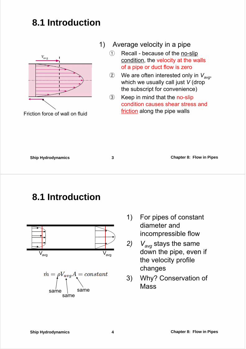
1) For pipes of constant di t ddiameter and incompressible flow
2) V sta s the same2) Vavg stays the same down the pipe, even if the velocity profile
Vavg Vavg
the velocity profile changes
3) Why? Conservation of ) yMass
samesame
same
Chapter 8: Flow in PipesShip Hydrodynamics 4
8.1 Introduction
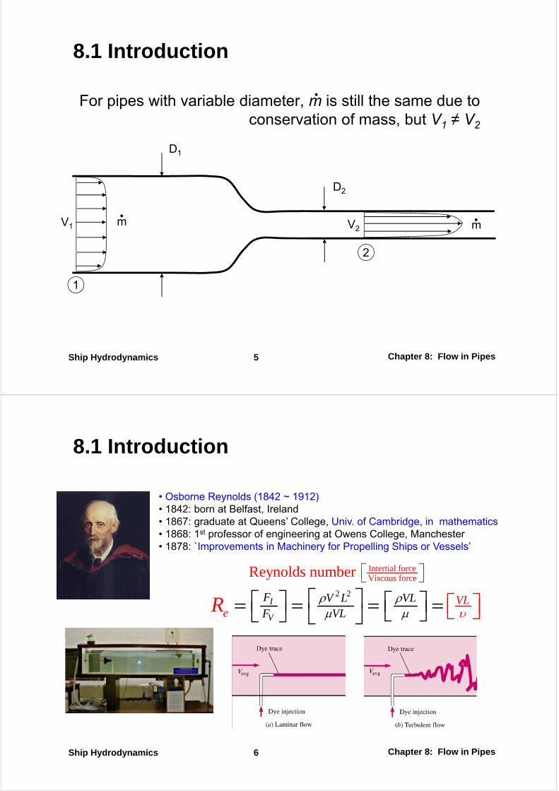
For pipes with variable diameter, m is still the same due to conservation of mass, but V1 ≠ V2
D1
D2
1
V2V1 m m
2
11
Chapter 8: Flow in PipesShip Hydrodynamics 5
8.1 Introduction
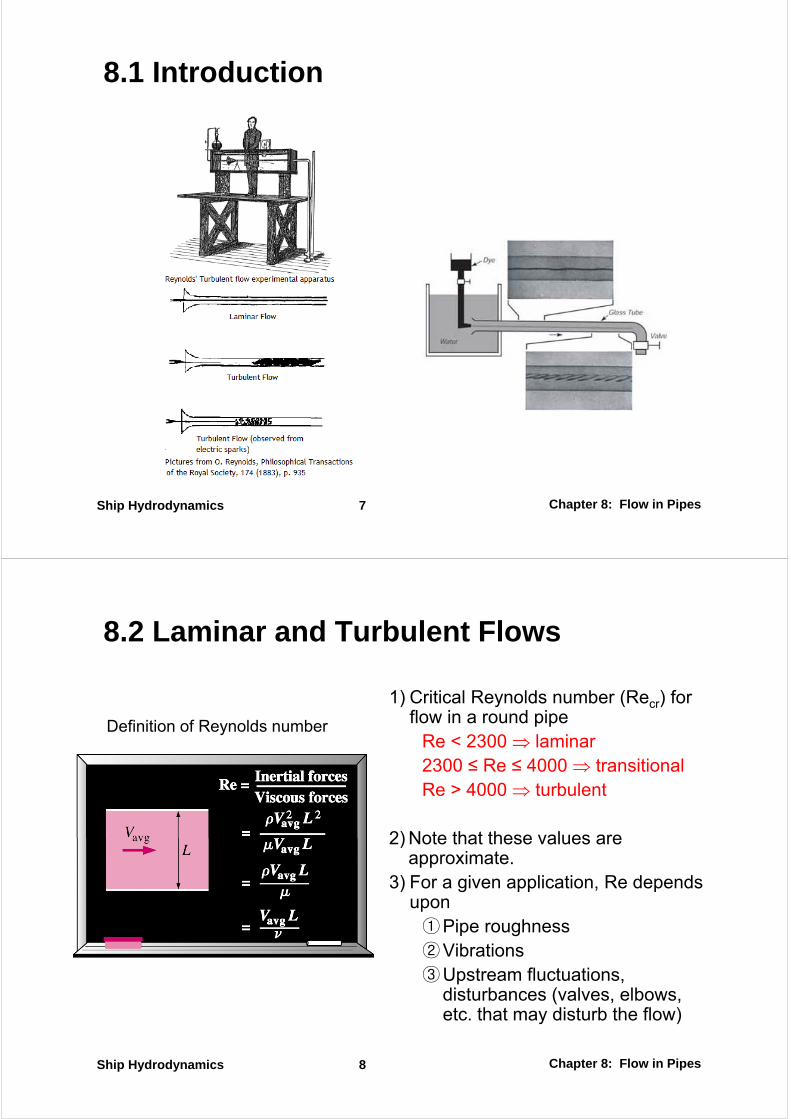
• Osborne Reynolds (1842 ~ 1912)1842 b B lf I l d• 1842: born at Belfast, Ireland
• 1867: graduate at Queens’ College, Univ. of Cambridge, in mathematics• 1868: 1st professor of engineering at Owens College, Manchester• 1878: `Improvements in Machinery for Propelling Ships or Vessels’1878: Improvements in Machinery for Propelling Ships or Vessels
Intertial forceViscous forceReynolds number ⎡ ⎤⎣ ⎦
2 2⎡ ⎤⎡ ⎤ ⎡ ⎤2 2
I
V
F V L VLe V
VL
LFR υ
ρ ρμ μ
⎡ ⎤⎡ ⎤ ⎡ ⎤= = = =⎣ ⎦⎣ ⎦ ⎣ ⎦ ⎡ ⎤⎣ ⎦
Chapter 8: Flow in PipesShip Hydrodynamics 6
8.1 Introduction
Chapter 8: Flow in PipesShip Hydrodynamics 7
8.2 Laminar and Turbulent Flows
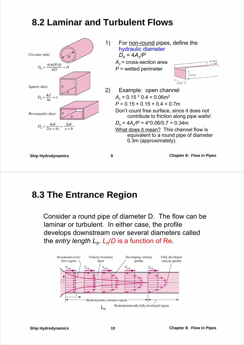
1) Critical Reynolds number (Recr) for flow in a round pipeflow in a round pipe
Re < 2300 ⇒ laminar2300 ≤ Re ≤ 4000 ⇒ transitional
Definition of Reynolds number
Re > 4000 ⇒ turbulent
2) Note that these values are2) Note that these values are approximate.
3) For a given application, Re depends uponupon①Pipe roughness②Vibrations③Upstream fluctuations,
disturbances (valves, elbows, etc. that may disturb the flow)
Chapter 8: Flow in PipesShip Hydrodynamics 8
8.2 Laminar and Turbulent Flows
1) For non-round pipes, define the h dra lic diameterhydraulic diameter Dh = 4Ac/P
Ac = cross-section areaP tt d i tP = wetted perimeter
2) Example: open channelAc = 0.15 * 0.4 = 0.06m2
P = 0.15 + 0.15 + 0.4 = 0.7mP 0.15 0.15 0.4 0.7mDon’t count free surface, since it does not
contribute to friction along pipe walls!Dh = 4Ac/P = 4*0.06/0.7 = 0.34mDh 4Ac/P 4 0.06/0.7 0.34mWhat does it mean? This channel flow is
equivalent to a round pipe of diameter 0.3m (approximately).
Chapter 8: Flow in PipesShip Hydrodynamics 9
8.3 The Entrance Region
Consider a round pipe of diameter D. The flow can be laminar or turbulent. In either case, the profile develops downstream over several diameters called th t l th L L /D i f ti f Rthe entry length Lh. Lh/D is a function of Re.
Lh
Chapter 8: Flow in PipesShip Hydrodynamics 10

8.3 The Entrance Region
,laminar
1/4
0.05 RehL D≅1/4
,turbuent
,turbuent
1.359 Re
10h
h
L D
L D
≅
≈
Chapter 8: Flow in PipesShip Hydrodynamics 11
,
8.4 Laminar Flow in Pipes
Average velocity:
( ) ( )(2 ) (2 ) (2 ) (2 ) 0x x dx r r dr
d d
rdrP rdrP rdx rdx
r rP P
π π π τ π τ
τ τ+ +− + − =
−− ( ) ( )0
, 0
x dx x r dr rP Pr
dx drdx dr
+ ++ =
→
( ),
0d rdP
rdx dr
τ+ =
dx drdu
drτ μ≡ −
drd du dP
rr dr dr dx
μ ⎛ ⎞ =⎜ ⎟⎝ ⎠
Chapter 8: Flow in PipesShip Hydrodynamics 12
⎝ ⎠
8.4 Laminar Flow in Pipes
2
1 2( ) ln 4
r dPu r C r C
dxμ⎛ ⎞= + +⎜ ⎟⎝ ⎠
2 wdP
dx R
τ= −
2 2
2( ) 1
4
R dP ru r
dx Rμ⎡ ⎤⎛ ⎞= − −⎜ ⎟ ⎢ ⎥⎝ ⎠ ⎣ ⎦
⎡ ⎤2 2 2
2 2 20 0
2
2 2( ) 1
4 8
R R
avg
R dP r R dPV u r rdr rdr
R R dx R dxμ μ⎡ ⎤⎛ ⎞ ⎛ ⎞= = − − − = −⎜ ⎟ ⎜ ⎟⎢ ⎥⎝ ⎠ ⎝ ⎠⎣ ⎦
⎡ ⎤
∫ ∫2
2( ) 2 1
at 0
avg
ru r V
R
r
⎡ ⎤= −⎢ ⎥
⎣ ⎦=
02 2
( ) ( )22
( )c
R
c RA
avg
u r dA u r rdr
V u r rdrA R R
ρ ρ π= = =∫ ∫
∫max
at 0
2 avg
r
u V
==
The average velocity in fully developed laminar pipe flow is one half of the maximum velocity
2 20
( )avgcA R Rρ ρπ ∫
Chapter 8: Flow in PipesShip Hydrodynamics 13
y
8.4 Laminar Flow in Pipes
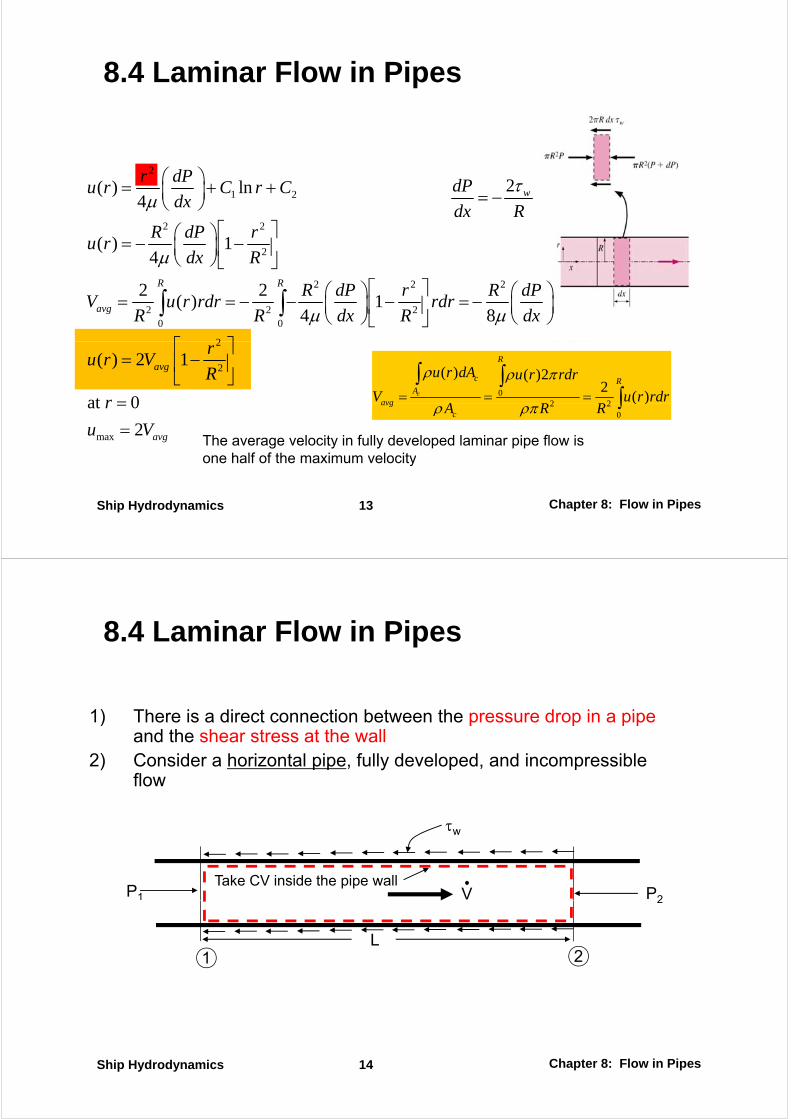
1) There is a direct connection between the pressure drop in a pipe1) There is a direct connection between the pressure drop in a pipe and the shear stress at the wall
2) Consider a horizontal pipe, fully developed, and incompressible floflow
τw
P1 P2VTake CV inside the pipe wall
1 2L
2
1
Chapter 8: Flow in PipesShip Hydrodynamics 14

8.4 Laminar Flow in Pipes
Pressure Drop: 2
avg
R dPV ⎛ ⎞= − ⎜ ⎟
⎝ ⎠2 1
8 32
dP P P
dx LLV LVμ μ
−=
8avgVdxμ ⎜ ⎟
⎝ ⎠
1 2 2 2
8 32avg avgLV LVP P P
R D
μ μΔ = − = =
2avgVL
P fρ
Δ
2
28
: Darcy friction factor
avgL
w
P fD
fV
ρ
τ
Δ =
≡2
y
64 64
Re
avg
fV
fDV
ρ
μρ
≡ =ReavgDVρ
In laminar flow, the friction factor is a function of the Reynolds number only and is independent of the roughness of the pipe surface
Chapter 8: Flow in PipesShip Hydrodynamics 15
8.4 Laminar Flow in Pipes
Head Loss: equivalent fluid column height
2
P gh
VP L
ρΔ =
ΔPoiseuille’s law: pressure drop and requiring power is proportional to the length of the pipe and the
2avg
L
VP Lh f
g D gρΔ
= =is proportional to the length of the pipe and the viscosity of the fluid, inversely proportional to the fourth power of the radius of the pipe
2 2 21 2 1 2( ) ( )
pump L LW V P V gh mgh
P P R P P D PDV
ρ= Δ = =
− − Δ= = =
2 4 421 2 1 2
8 32 32
( ) ( )
avg
avg c
VL L L
P P R P P D P DV V A R
μ μ μπ ππ− − Δ
= = = =
4
8 128 128
128
avg c
avg c
L L L
LP V A
D
μ μ μμ
Δ =
Chapter 8: Flow in PipesShip Hydrodynamics 16
4g Dπ
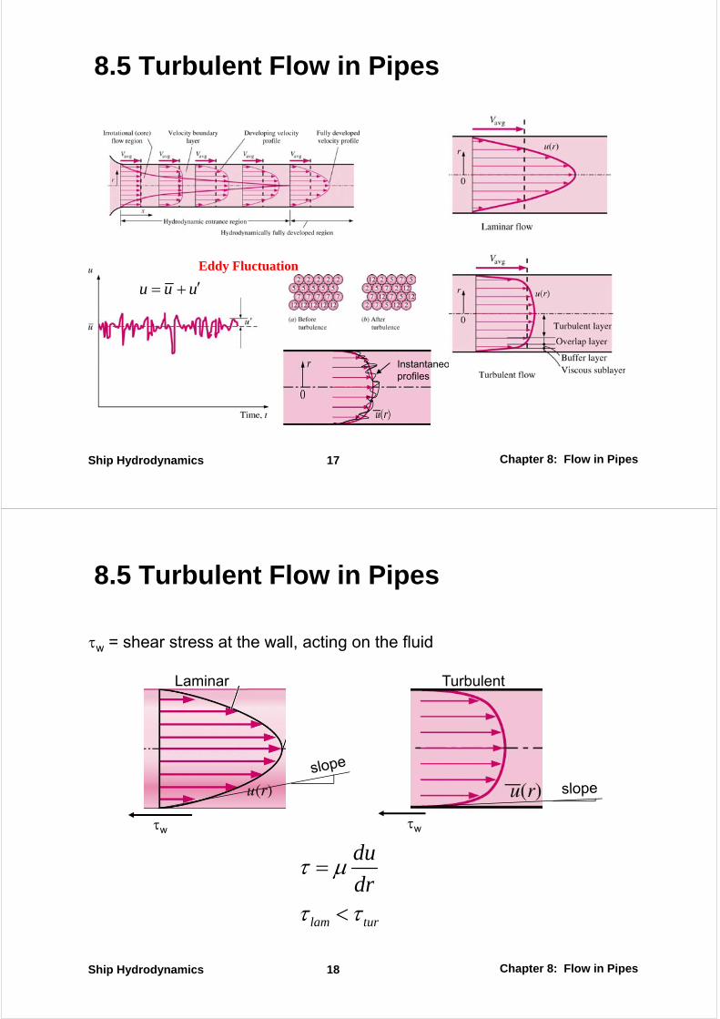
8.5 Turbulent Flow in Pipes
u u u′= +Eddy Fluctuation
InstantaneousInstantaneousprofiles
Chapter 8: Flow in PipesShip Hydrodynamics 17
8.5 Turbulent Flow in Pipes
τw = shear stress at the wall, acting on the fluid
Laminar Turbulent
w g
τw τw
du
dτ μ=
lam tur
drμ
τ τ<
Chapter 8: Flow in PipesShip Hydrodynamics 18

8.5 Turbulent Flow in Pipes
Turbulent shear stress:Tangential(Shear) Force:
( )( )F v dA u u v dA
F
δ ρ ρδ
′ ′ ′ ′= − = −
Fu v
dA
δ ρ ′ ′= −
′ ′turb u vτ ρ ′ ′≡ −Reynolds stress or Turbulent stress
0, 0, 0, 0u v u v u v′ ′ ′ ′ ′ ′= = = ≠
total lam tur
duu v
dyτ τ τ μ ρ
⎛ ⎞′ ′= + = − +⎜ ⎟⎝ ⎠
Chapter 8: Flow in PipesShip Hydrodynamics 19
y⎝ ⎠
8.5 Turbulent Flow in Pipes
u∂Joseph Boussinesq:
: eddy viscosity or turbulent viscosity
turb t
t
uu v
yτ ρ μ
μ
∂′ ′= − =∂
2
2u ulτ μ ρ⎛ ⎞∂ ∂
= = ⎜ ⎟
L. Prandtl:
∂ ∂: mixing length
turb t mly y
l
τ μ ρ= = ⎜ ⎟∂ ∂⎝ ⎠
( ) ( )
/ : kinematic eddy viscosity
toal t t
u u
y yτ μ μ ρ ν ν
ν μ ρ
∂ ∂= + = +
∂ ∂≡ / : kinematic eddy viscosity
kinematic turbulent viscosity
eddy diffusivity of momentum
t tν μ ρ≡
Chapter 8: Flow in PipesShip Hydrodynamics 20
eddy diffusivity of momentum
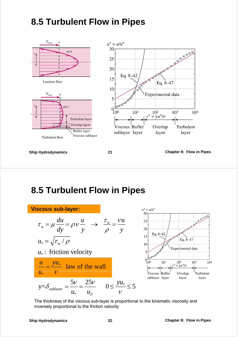
8.5 Turbulent Flow in Pipes
Chapter 8: Flow in PipesShip Hydrodynamics 21
8.5 Turbulent Flow in Pipes
Viscous sub-layer:
ww
du u u
dy y y
τ ντ μ ρνρ
= = → =
* /
: friction velocitywu
u
τ ρ=
*
*
: friction velocity
law of the wall
u
u yu
u ν=
*
*5 25y= 0 5sublayer
u
yu
νν νδ = = ≤ ≤*
y sublayer u uδ νThe thickness of the viscous sub-layer is proportional to the kinematic viscosity and inversely proportional to the friction velocity
Chapter 8: Flow in PipesShip Hydrodynamics 22
y p p y
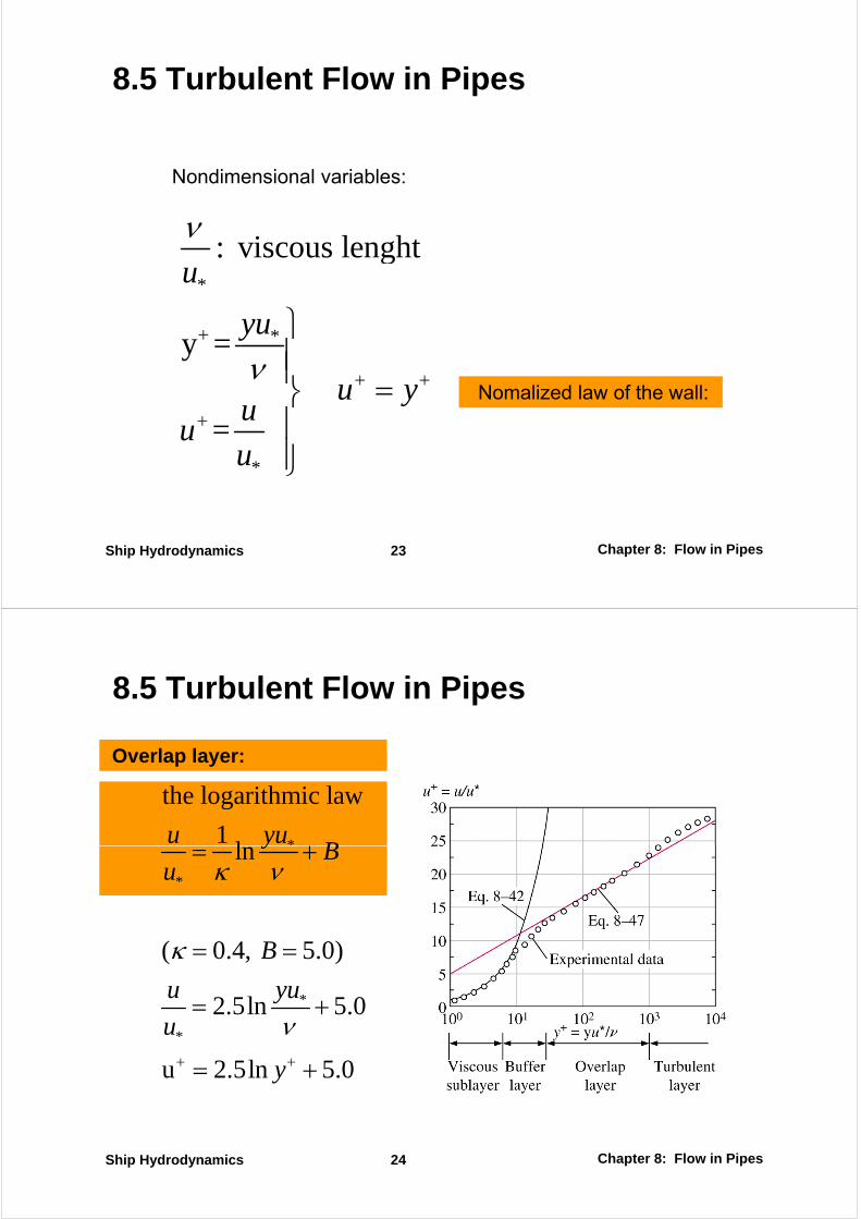
8.5 Turbulent Flow in Pipes
N di i l i bl
i l hν
Nondimensional variables:
*
: viscous lenghtu
ν
*y =yu
ν+ ⎫
⎪⎪
=u y
uu
ν + +
+
⎪ =⎬⎪⎪
Nomalized law of the wall:
*
uu ⎪⎭
Chapter 8: Flow in PipesShip Hydrodynamics 23
8.5 Turbulent Flow in Pipes
Overlap layer:
*
the logarithmic law
1l
u yuB+
*
ln y
Bu κ ν
= +
( 0.4, 5.0)Bκ = =
*
*
2.5ln 5.0 u yu
u ν= +
u 2.5ln 5.0y+ += +
Chapter 8: Flow in PipesShip Hydrodynamics 24

8.5 Turbulent Flow in Pipes
Outer turbulent layer:
max
velocity defect law:
2 5lnu u R−
=*
2.5ln
power-law velocity profile:
u R r=
−
1/
max
nu y
u R⎛ ⎞= ⎜ ⎟⎝ ⎠
1/
max
1n
u r
u R⎛ ⎞= −⎜ ⎟⎝ ⎠max
one-seventh power-law
Chapter 8: Flow in PipesShip Hydrodynamics 25
8.5 Moody chart
Colebrook:Colebrook:
1 / 2.512.0log
3 7 Re
D
f f
ε⎛ ⎞= − +⎜ ⎟⎜ ⎟
⎝ ⎠3.7 Ref f⎜ ⎟⎝ ⎠
1 11
Haaland:
⎛ ⎞⎛ ⎞1.11
1 6.9 /1.8log
Re 3.7
D
f
ε⎛ ⎞⎛ ⎞≅ − +⎜ ⎟⎜ ⎟⎜ ⎟⎝ ⎠⎝ ⎠
Chapter 8: Flow in PipesShip Hydrodynamics 26
8.5 Moody chart
Types of Pipe Flow Problems
2VL2
4
2avgVL
P fD
P D
ρ
π
Δ =
Δ128
P DV
L
πμ
Δ=
Chapter 8: Flow in PipesShip Hydrodynamics 27
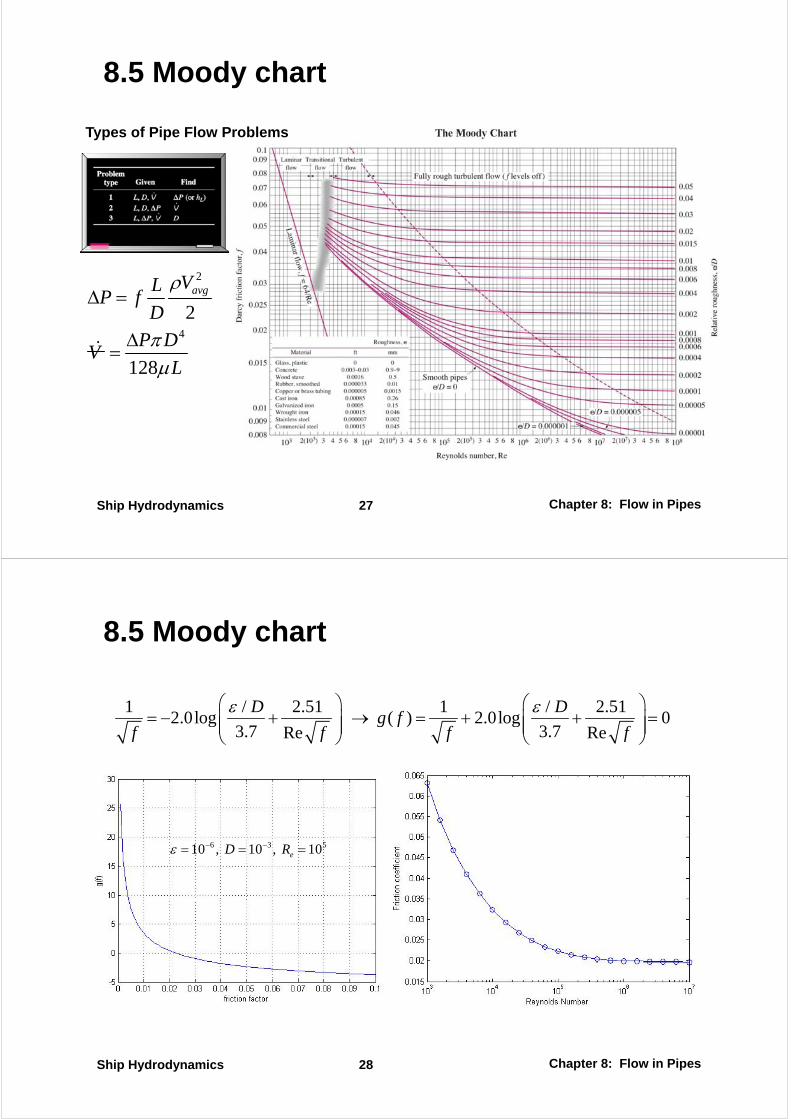
8.5 Moody chart
1 / 2.51 1 / 2.512 0l ( ) 2 0l 0
D Df
ε ε⎛ ⎞ ⎛ ⎞+ → + +⎜ ⎟ ⎜ ⎟2.0log ( ) 2.0log 0
3.7 3.7Re Reg f
f f f f= − + → = + + =⎜ ⎟ ⎜ ⎟⎜ ⎟ ⎜ ⎟
⎝ ⎠ ⎝ ⎠
6 3 510 , 10 , 10eD Rε − −= = =
Chapter 8: Flow in PipesShip Hydrodynamics 28
8.8 Flow Rate and Velocity Measurement
1) Pitot and Pitot-Static Probes2) Obstruction Flow meters:2) Obstruction Flow-meters: ① Orifice② Venturi Meter③ N l M t③ Nozzle Meter
3) Positive Displacement Flow-meters4) Turbine Flow-meters5) Paddlewheel Flow-meters6) Variable Area Flow-meters7) Ultrasonic Flow-meters)8) Doppler-Effect Ultrasonic Flow-meters9) Electromagnetic Flow-meters10) Vortex Flow-meters10) Vortex Flow meters11) Thermal (Hot-wire) Anemometers12) Laser Doppler Velocimetry (LDV)13) Particle Image Velocimetry (PIV)
Chapter 8: Flow in PipesShip Hydrodynamics 29
13) Particle Image Velocimetry (PIV)
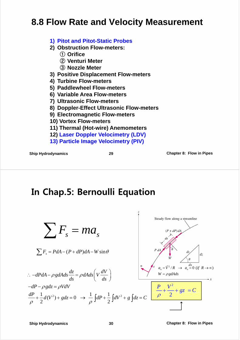
In Chap.5: Bernoulli Equation
s sF ma=∑( ) sinsF PdA P dP dA W θ= − + −∑
s s∑
2 / 0 ( )n na V R a if R
W gdAdsρ= → = →∞
∑
dz dVdPdA dAd dAd V⎛ ⎞
⎜ ⎟ W gdAdsρ=
1 1 1
dPdA gdAds dAds Vds ds
dP gdz VdV
d
ρ ρ
ρ ρ
⎛ ⎞∴− − = ⎜ ⎟⎝ ⎠
− − = 2P Vgz C+ + =
2 21 1 1( ) 0
2 2
dPd V gdz dP dV g dz C
ρ ρ+ + = → + + =∫ ∫ ∫ 2
gρ
Chapter 8: Flow in PipesShip Hydrodynamics 30
In Chap. 5: Euler & Bernoulli Equation
1) The Bernoulli equation was first stated in words by the Swiss mathematician Daniel Bernoulli (1700~1782) in a text written in 1738. It was later derived in general equation from by Leonhard Euler (1707 1783) in 1755from by Leonhard Euler (1707~1783) in 1755.
2) The Bernoulli equation is derived assuming incompressible & inviscid flow, and thus is should not be used fro flows with significant compressibility effects.
3) Unsteady, Compressible Flow:
4) St d C ibl Fl
2
2
dP V Vds gz C
tρ∂
+ + + =∂∫ ∫
4) Steady, Compressible Flow:2
2
dP Vgz C
ρ+ + =∫
5) Steady, Incompressible Flow:
2P V 2
[J]2
P Vgz C
ρ+ + =
The sum of the kinetic, potential, and flow energies of a fluid particle is constant along a streamline during
Chapter 8: Flow in PipesShip Hydrodynamics 31
constant along a streamline during steady flow
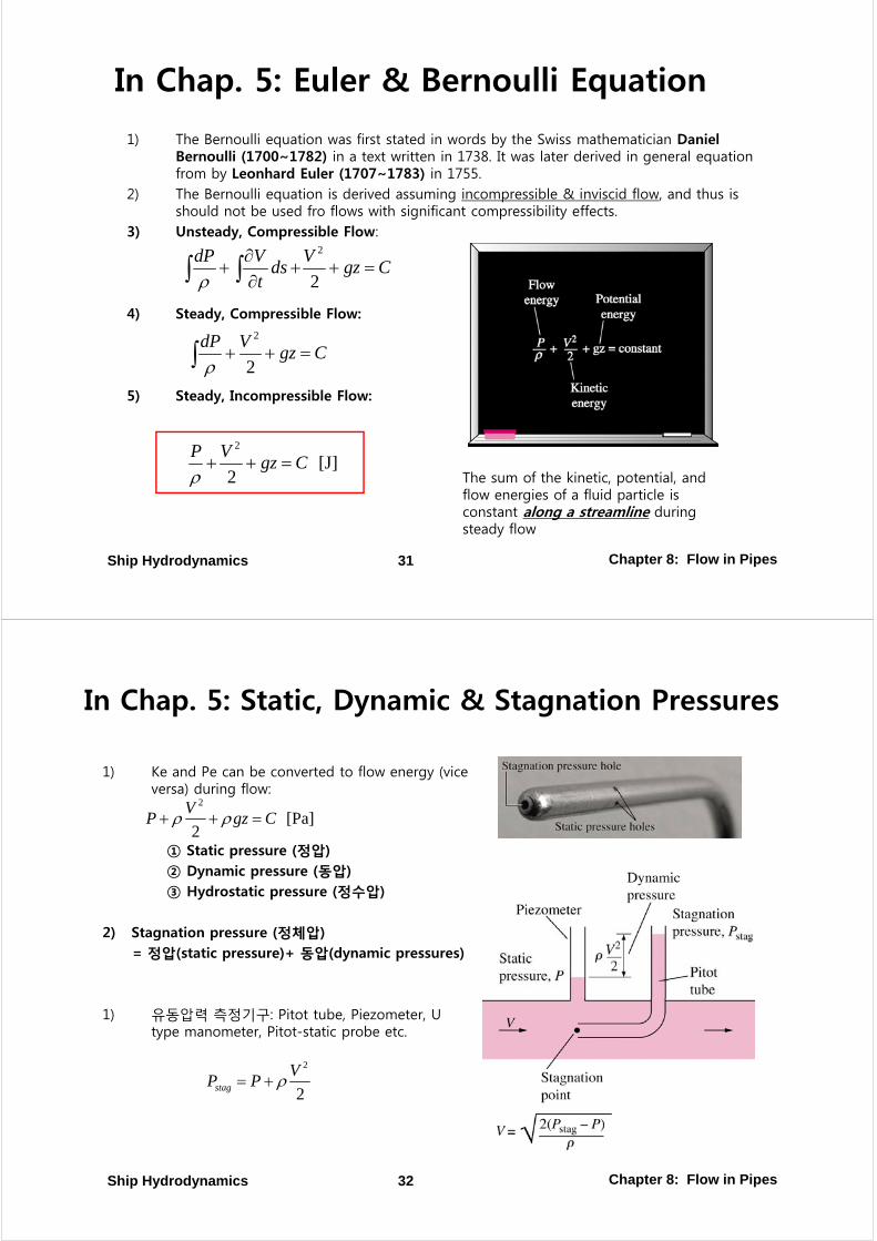
In Chap. 5: Static, Dynamic & Stagnation Pressures
1) Ke and Pe can be converted to flow energy (vice versa) during flow:versa) during flow:
① Static pressure (정압)
2
[Pa]2
VP gz Cρ ρ+ + =
② Dynamic pressure (동압)③ Hydrostatic pressure (정수압)
2) Stagnation press re (정체압)2) Stagnation pressure (정체압)= 정압(static pressure)+ 동압(dynamic pressures)
1) 유동압력 측정기구: Pitot tube, Piezometer, U type manometer, Pitot-static probe etc.
2V 2
2stag
VP P ρ= +
Chapter 8: Flow in PipesShip Hydrodynamics 32
![Chapter 11BW.ppt [호환 모드] - CNU FINCLfincl.cnu.ac.kr/lecture/shiphydrodynamics/Chapter_11BW.pdf · NACA2412 0.2524 L C = 0.0002 D C = 0.0003 D C = Chapter 11: Flow over bodies;](https://img.pdfslide.net/doc/110x75/5ab4fff47f8b9ab47e8c6b67/chapter-11bwppt-cnu-02524-l-c-00002-d-c-00003-d-c-chapter.jpg)