Embed Size (px)
Citation preview

Silberschatz, Galvin and Gagne ©2013 Operating System Concepts – 9th Edition
Chapter 8: Main Memory

8.2 Silberschatz, Galvin and Gagne ©2013 Operating System Concepts – 9th Edition
Chapter 8: Memory Management
Background
Swapping
Contiguous Memory Allocation
Segmentation
Paging
Structure of the Page Table
Example: The Intel 32 and 64-bit Architectures
Example: ARM Architecture

8.3 Silberschatz, Galvin and Gagne ©2013 Operating System Concepts – 9th Edition
Objectives
To increase CPU utilization and response speed:
Several processes must be kept in main memory
We must share memory
How to manage main memory resource…?
To provide a detailed description of various ways of organizing memory hardware
To discuss various memory-management techniques, including paging and
segmentation
To provide a detailed description of the Intel Pentium, which supports both pure
segmentation and segmentation with paging
8.4 Silberschatz, Galvin and Gagne ©2013 Operating System Concepts – 9th Edition
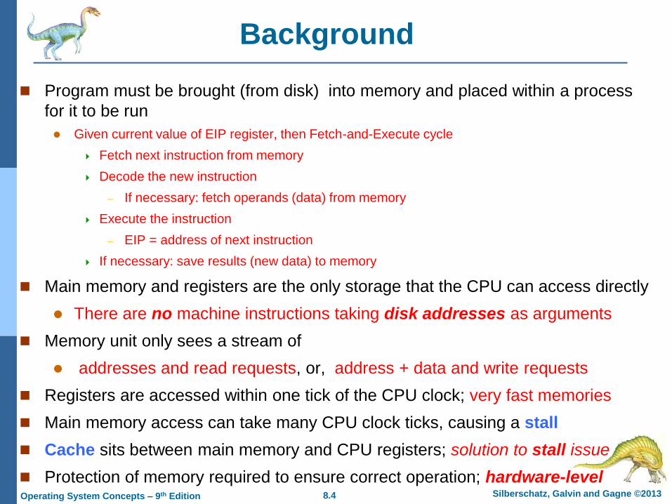
Background
Program must be brought (from disk) into memory and placed within a process
for it to be run
Given current value of EIP register, then Fetch-and-Execute cycle
Fetch next instruction from memory
Decode the new instruction
– If necessary: fetch operands (data) from memory
Execute the instruction
– EIP = address of next instruction
If necessary: save results (new data) to memory
Main memory and registers are the only storage that the CPU can access directly
There are no machine instructions taking disk addresses as arguments
Memory unit only sees a stream of
addresses and read requests, or, address + data and write requests
Registers are accessed within one tick of the CPU clock; very fast memories
Main memory access can take many CPU clock ticks, causing a stall
Cache sits between main memory and CPU registers; solution to stall issue
Protection of memory required to ensure correct operation; hardware-level

8.5 Silberschatz, Galvin and Gagne ©2013 Operating System Concepts – 9th Edition
Base and Limit Registers
For each process, the base and limit registers define its logical address space
To protect processes from each; each process has its own memory space
Base register holds the smallest legal physical memory address
Limit register specifies the size of the range of accessible addresses
CPU must check every memory access generated in user mode to be sure it is
between base and limit for that user; to protect a process’s memory space

8.6 Silberschatz, Galvin and Gagne ©2013 Operating System Concepts – 9th Edition
Hardware Address Protection
• Base and limit registers loaded only by the OS through a privileged instruction
• To prevent users from changing these registers’ contents
• OS has unrestricted access to OS memory and user memory
• Load users’ programs into users’ memory, … etc
• Access and modify system-calls’ parameter, … etc
8.7 Silberschatz, Galvin and Gagne ©2013 Operating System Concepts – 9th Edition
Address Binding
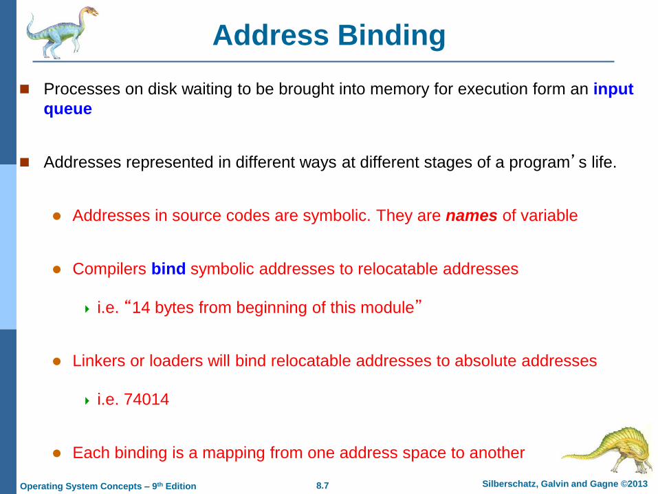
Processes on disk waiting to be brought into memory for execution form an input
queue
Addresses represented in different ways at different stages of a program’s life.
Addresses in source codes are symbolic. They are names of variable
Compilers bind symbolic addresses to relocatable addresses
i.e. “14 bytes from beginning of this module”
Linkers or loaders will bind relocatable addresses to absolute addresses
i.e. 74014
Each binding is a mapping from one address space to another

8.8 Silberschatz, Galvin and Gagne ©2013 Operating System Concepts – 9th Edition
Binding of Instructions and Data to Memory
Address binding of instructions and data to memory addresses can happen at
three different stages
Compile time: If memory location is known a priori at compile time, absolute
code can be generated; must recompile code if starting location changes
If a process will reside at location L then its compile code will start at L
Source code should be re-compiled if L changes
Load time: Compiler must generate relocatable code if memory location of
the process is not known at compile time
That is, final binding is delayed until load time
Execution time: Binding delayed until run time if the process can be moved
during its execution from one memory segment to another
Need hardware support for address maps (e.g., base and limit registers)

8.9 Silberschatz, Galvin and Gagne ©2013 Operating System Concepts – 9th Edition
Multistep Processing of a User Program

8.10 Silberschatz, Galvin and Gagne ©2013 Operating System Concepts – 9th Edition
Logical vs. Physical Address Space
The concept of a logical address space that is bound to a separate physical
address space is central to proper memory management
Logical address – generated by the CPU;
Also referred to as virtual address
Physical address – address seen by the memory-management unit in its
memory-address register
The compile-time and load-time address-binding schemes generate identical
logical and physical addresses;
The execution-time address-binding scheme results in differing logical and
physical addresses; hence, we refer to logical address as virtual address
Logical address space is the set of all logical addresses generated by a
program
Physical address space is the set of all physical addresses corresponding to
these logical addresses
8.11 Silberschatz, Galvin and Gagne ©2013 Operating System Concepts – 9th Edition
Memory-Management Unit (MMU)
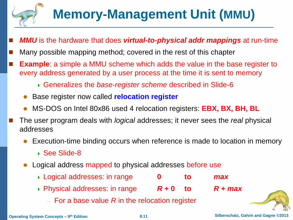
MMU is the hardware that does virtual-to-physical addr mappings at run-time
Many possible mapping method; covered in the rest of this chapter
Example: a simple a MMU scheme which adds the value in the base register to
every address generated by a user process at the time it is sent to memory
Generalizes the base-register scheme described in Slide-6
Base register now called relocation register
MS-DOS on Intel 80x86 used 4 relocation registers: EBX, BX, BH, BL
The user program deals with logical addresses; it never sees the real physical
addresses
Execution-time binding occurs when reference is made to location in memory
See Slide-8
Logical address mapped to physical addresses before use
Logical addresses: in range 0 to max
Physical addresses: in range R + 0 to R + max
– For a base value R in the relocation register

8.12 Silberschatz, Galvin and Gagne ©2013 Operating System Concepts – 9th Edition
Dynamic relocation using a relocation register
(Dynamic Loading)
A user routine is not loaded until it is
called Loading is delayed until run-time
Better memory-space utilization; unused
routine is never loaded
All routines kept on disk in relocatable
load format
Useful when large amounts of code are
needed to handle infrequently occurring
cases. Loaded program portion is much
smaller than total program
No special support from the operating
system is required
Implemented through program design
OS can help users by providing
libraries to implement dynamic loading

8.13 Silberschatz, Galvin and Gagne ©2013 Operating System Concepts – 9th Edition
Dynamic Linking
Static linking – system libraries and program code combined by the loader into
the binary program image (the final executable file)
Dynamic linking – the linking is postponed until execution-time
The executing program (the running process)
Small piece of code, the stub, indicates how to locate the appropriate memory-
resident library routine, or, how to load the library if routine is not already present
Operating system checks if the needed routine is in the process’s memory space
If not in address space, then load the library routine; when stub is executed
Stub replaces itself with the address of the routine and executes the routine
Dynamic linking is particularly useful for [large] system libraries
Very useful also for shared libraries with different version numbers
Consider applicability to patching system libraries
Versioning may be needed

8.14 Silberschatz, Galvin and Gagne ©2013 Operating System Concepts – 9th Edition
Swapping
A process can be swapped temporarily out of memory to a backing store, and then brought back into memory for continued execution
Total physical memory space of processes can exceed physical memory
Hence, swapping increases the degree of multiprogramming
Backing store – fast disk large enough to accommodate copies of all memory images for all users; must provide direct access to these memory images
System maintains a ready queue of ready-to-run processes which have memory images on the backing store or in memory. Standard swapping method:
Dispatcher called when the CPU scheduler selects a process P from queue
If P is not in the ready queue and not enough free space in memory for P
– Swap in P from backing store and swap out some Q from memory
– Reload registers and transfer control to P; i.e. P is now in running state
The context-switch time in standard swapping is fairly high; see Slide-16
Roll out, roll in – swapping variant used for priority-based scheduling algorithms; lower-priority process is swapped out so higher-priority process can be loaded and executed
Also, see medium-term scheduler in Chap-3

8.15 Silberschatz, Galvin and Gagne ©2013 Operating System Concepts – 9th Edition
Schematic View of Swapping (Swapping of two processes using a disk as a backing store)
8.16 Silberschatz, Galvin and Gagne ©2013 Operating System Concepts – 9th Edition
Context Switch Time including Swapping
Context-switch time in swapping is very high
Assume swapping 100MB to backing store with a transfer rate of 50MB/sec
Swap out time of a process is 2000 ms (= 2 seconds)
Swap in time of a same sized process is also 2000 ms
Total context-switch swapping component time is 4000ms (= 4 seconds)
We have ignored other components of context-switch time and ignored other
disk performance aspect. But, the major part of swap time is transfer time
Total transfer time is directly proportional to the amount of memory swapped
We can reduce if we know exactly how much memory a process is using
Process with dynamic memory requirements will issue system-calls to inform OS of memory use via request_memory() and release_memory()
8.17 Silberschatz, Galvin and Gagne ©2013 Operating System Concepts – 9th Edition
Context Switch Time and Swapping
Other constraints as well on swapping
Does the swapped out process need to swap back in to same physical addresses?
Depends on address binding method
A process must be completely idle before being swapped out; not just waiting
Consider pending I/O to/from process memory space
We can’t swap out the process since I/O would occur to wrong process
Solutions:
– Never swap out a process with pending I/O
– Or, always transfer I/O operations to kernel space, then to I/O device
» Known as double buffering, adds overhead

8.18 Silberschatz, Galvin and Gagne ©2013 Operating System Concepts – 9th Edition
Modified Standard Swapping
Standard swapping not used in modern operating systems
But modified version are common
Idea: swap only when free memory is extremely low
Modified versions of swapping are found on many systems
UNIX, Linux, and Windows
Swapping normally disabled
Started only if amount of free memory falls below a threshold amount
Disabled again once amount of free memory increases beyond some
threshold

8.19 Silberschatz, Galvin and Gagne ©2013 Operating System Concepts – 9th Edition
Swapping on Mobile Systems
Not typically supported in any form, because:
Mobile devices use flash memory as persistent storage
Small amount of space
Limited number of write cycles
Poor throughput between flash memory and CPU on mobile platforms
– Number of I/O operations that can be completed per time units
Instead, mobile devices use other methods to free up memory if low space
iOS asks apps to voluntarily relinquish allocated memory
Read-only data (e.g., codes) removed then reloaded from flash if needed
iOS may terminate any apps that fail to free up memory
Android adopts a similar strategy as iOS. But, for fast restart
It first saves application state to flash before terminating an app
Both OS’s support paging as discussed in Slide-27

8.20 Silberschatz, Galvin and Gagne ©2013 Operating System Concepts – 9th Edition
Contiguous Allocation
Main memory must support both OS and user processes
Limited memory resource; thus, must allocate efficiently
Main memory is usually divided into two partitions:
Resident OS usually placed in low memory together with the interrupt vector
User processes then held in high memory
Each process is contained in a single contiguous section of memory
Contiguous memory allocation is one early method
Each process is placed contiguous to each other in memory
8.21 Silberschatz, Galvin and Gagne ©2013 Operating System Concepts – 9th Edition
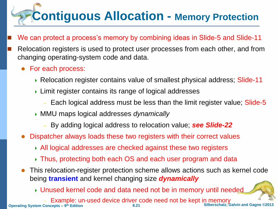
Contiguous Allocation - Memory Protection
We can protect a process’s memory by combining ideas in Slide-5 and Slide-11
Relocation registers is used to protect user processes from each other, and from
changing operating-system code and data.
For each process:
Relocation register contains value of smallest physical address; Slide-11
Limit register contains its range of logical addresses
– Each logical address must be less than the limit register value; Slide-5
MMU maps logical addresses dynamically
– By adding logical address to relocation value; see Slide-22
Dispatcher always loads these two registers with their correct values
All logical addresses are checked against these two registers
Thus, protecting both each OS and each user program and data
This relocation-register protection scheme allows actions such as kernel code
being transient and kernel changing size dynamically
Unused kernel code and data need not be in memory until needed
– Example: un-used device driver code need not be kept in memory

8.22 Silberschatz, Galvin and Gagne ©2013 Operating System Concepts – 9th Edition
Hardware Support for Relocation and Limit Registers
8.23 Silberschatz, Galvin and Gagne ©2013 Operating System Concepts – 9th Edition
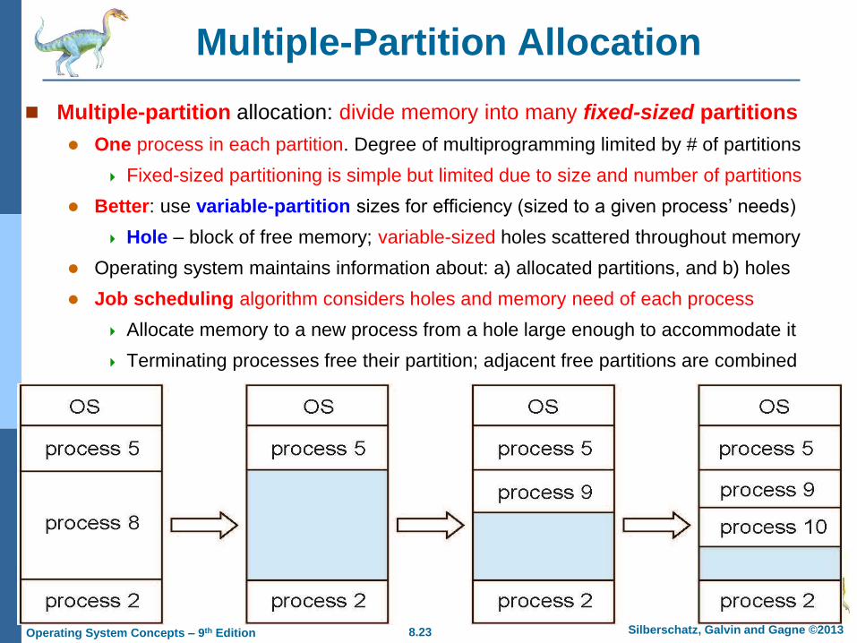
Multiple-Partition Allocation
Multiple-partition allocation: divide memory into many fixed-sized partitions
One process in each partition. Degree of multiprogramming limited by # of partitions
Fixed-sized partitioning is simple but limited due to size and number of partitions
Better: use variable-partition sizes for efficiency (sized to a given process’ needs)
Hole – block of free memory; variable-sized holes scattered throughout memory
Operating system maintains information about: a) allocated partitions, and b) holes
Job scheduling algorithm considers holes and memory need of each process
Allocate memory to a new process from a hole large enough to accommodate it
Terminating processes free their partition; adjacent free partitions are combined

8.24 Silberschatz, Galvin and Gagne ©2013 Operating System Concepts – 9th Edition
Dynamic Storage-Allocation Problem
How to satisfy a request of size n from a list of free holes?
First-fit: Allocate the first hole that is big enough
Best-fit: Allocate the smallest hole that is big enough; must search entire list, unless ordered by size
Produces the smallest leftover hole
Worst-fit: Allocate the largest hole; must search entire list, unless ordered by size
Produces the largest leftover hole
– Which may be more useful than the smaller leftover hole from a best-fit approach; see Slide-25
First-fit and best-fit better than worst-fit in terms of speed and storage utilization
First-fit is generally the fastest
8.25 Silberschatz, Galvin and Gagne ©2013 Operating System Concepts – 9th Edition
Fragmentation
External Fragmentation – total memory space exists to satisfy a request, but it
is not contiguous
Free memory space is broken into pieces as processes are loaded and
removed from memory
Both, first-fit and best-fit strategies suffer from external fragmentation
Statistical analysis of first-fit reveals that given N allocated blocks, 0.5N
blocks will be lost to fragmentation
That is, 1/3 of memory may be unusable -> 50-percent rule
Internal Fragmentation – allocated memory may be slightly larger than
requested memory; this size difference is memory internal to a partition, but not
being used.
Example: a process requests 18,462 bytes and is allocated memory hole of
18,464 bytes; we are then left with a hole of 2 bytes

8.26 Silberschatz, Galvin and Gagne ©2013 Operating System Concepts – 9th Edition
Fragmentation
Reduce external fragmentation by compaction
Shuffle memory contents to place all free memory together in one large block
Compaction is possible only if address relocation is dynamic, and is done at
execution time
I/O problem
Latch job in memory while it is involved in I/O
Do I/O only into OS buffers
Compaction can be very expensive in terms of time
All processes are moved toward one end of memory
Other solutions to external fragmentation problems: Segmentation and Paging
Permit the logical address space of each process to be non-contiguous
Process can be allocated physical memory wherever it is available
Now consider that backing store has same fragmentation problems
As processes are swapped in and out. Also true for any storage device

8.27 Silberschatz, Galvin and Gagne ©2013 Operating System Concepts – 9th Edition
Paging
Physical address space of a process can be non-contiguous; process is
allocated physical memory whenever the latter is available
Avoids external fragmentation and the need for compaction
Avoids problem of varying sized memory chunks
Paging
Divide physical memory into fixed-sized blocks called frames
Block size is a power of 2; between 512 bytes and 1 Gbytes
Divide logical memory into blocks of same size as the frames called pages
The page size (like the frame size) is defined by the hardware; see Slide-29
Divide backing store into [clusters of] blocks of same size as the frames
Keep track of all free frames
To run a program of size N pages, need to find N free frames and load program
Set up a page table to translate logical to physical addresses
Still have Internal fragmentation

8.28 Silberschatz, Galvin and Gagne ©2013 Operating System Concepts – 9th Edition
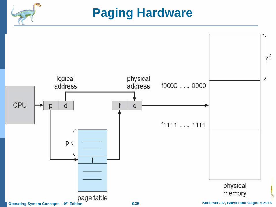
Address Translation Scheme
Each address generated by CPU is divided into two parts:
Page number (p) – used as an index into a page table
Page table contains the base address of each page in physical memory
Page offset (d) – combined with the base address to define the physical
memory address that is sent to the memory unit
If the logical address space is 2m and the page size is 2n
The binary representation of the logical address has m bits, such that
– The m – n leftmost bits designate the page number p
» p is index into the page table
– The rightmost n bits designate the page offset d
» d is displacement within the page
page number page offset
p d
m -n n
8.29 Silberschatz, Galvin and Gagne ©2013 Operating System Concepts – 9th Edition
Paging Hardware

8.30 Silberschatz, Galvin and Gagne ©2013 Operating System Concepts – 9th Edition
Paging Model of Logical and Physical Memory

8.31 Silberschatz, Galvin and Gagne ©2013 Operating System Concepts – 9th Edition
Paging Example
Example: n = 2 and m = 4 and using a 32-byte memory (8 pages) with 4-byte pages
Logical address 0 is page p=0, offset d=0; Page 0 is in frame f=5; [ (f × m) + d ]
Thus logical address 0 maps to physical address 20 [= (5 × 4) + 0];

8.32 Silberschatz, Galvin and Gagne ©2013 Operating System Concepts – 9th Edition
Paging
There is no external fragmentation when using paging scheme
Internal fragmentation is possible. Calculating internal fragmentation
Page size = 2,048 bytes
Process size = 72,766 bytes
Process has 35 pages + 1,086 bytes; thus, 36 frames required
Internal fragmentation of 2,048 - 1,086 = 962 bytes of un-used memory
Worst case fragmentation is when 1 frame contains only 1 byte of used mem
Average fragmentation is about 1-half page size per process
So: are small page sizes more desirable?
Not necessarily; each page-table entry takes memory to track (overhead)
Large frame sizes better when transferring data to/from disk; efficient disk I/O
Page size: 4KB ~ 8KB but growing over time, and researching variable page size
Solaris supports two page sizes – 8 KB and 4 MB; fixed multiple page sizes
Process view and physical memory now very different
By implementation process can only access its own memory

8.33 Silberschatz, Galvin and Gagne ©2013 Operating System Concepts – 9th Edition
Free Frames
Before allocation After allocation

8.34 Silberschatz, Galvin and Gagne ©2013 Operating System Concepts – 9th Edition
Implementation of Page Table
Process’s page table is kept in main memory
Page-table base register (PTBR) points to the page table
Page-table length register (PTLR) indicates size of the page table
Both, PTBR and PTLR are also stored in the process’s PCB
In this scheme every access to data or instruction requires two memory accesses
First: access the page table using PTBR value to retrieve its frame number
Second: access the actual memory location given the frame number
This is a serious time overhead that needs to reduced
The two-memory-access problem can be solved by the use of a special fast-
lookup hardware cache called associative memory or translation look-aside
buffers (TLBs)

8.35 Silberschatz, Galvin and Gagne ©2013 Operating System Concepts – 9th Edition
Associative Memory - TLB
Associative memory – parallel search
Address translation give (p, d)
If p is in associative memory, then retrieve the corresponding frame #
Otherwise retrieve the corresponding frame # from the page table in memory
This is a TLB miss; the page # and frame # are then added to the TLB for
future references
Page # Frame #

8.36 Silberschatz, Galvin and Gagne ©2013 Operating System Concepts – 9th Edition
Paging Hardware With TLB

8.37 Silberschatz, Galvin and Gagne ©2013 Operating System Concepts – 9th Edition
Implementation of Page Table
TLBs are typically small (64 to 1,024 entries)
On a TLB miss, new entry (p, f) is loaded into the TLB for faster access next time
Replacement policies must be considered; if TLB is already full. Examples:
LRU – Least Recently Used replacement algorithm
RR – Round Robin replacement algorithm
Random replacement algorithm
Some entries can be wired down for permanent fast access
Cannot be removed by any replacement algorithm
Some TLBs store address-space identifiers (ASIDs) in each TLB entry
Uniquely identifies each process and is used to provide address-space
protection for that process
Otherwise need to flush the current TLB at every context switch
8.38 Silberschatz, Galvin and Gagne ©2013 Operating System Concepts – 9th Edition
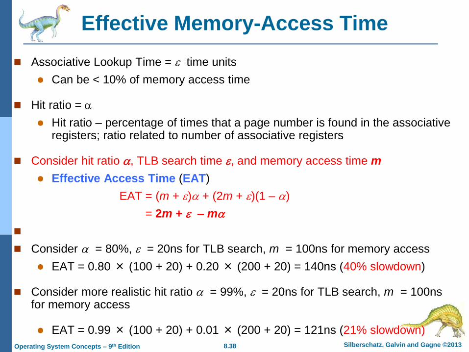
Effective Memory-Access Time
Associative Lookup Time = time units
Can be < 10% of memory access time
Hit ratio =
Hit ratio – percentage of times that a page number is found in the associative registers; ratio related to number of associative registers
Consider hit ratio , TLB search time , and memory access time m
Effective Access Time (EAT)
EAT = (m + ) + (2m + )(1 – )
= 2m + – m
Consider = 80%, = 20ns for TLB search, m = 100ns for memory access
EAT = 0.80 × (100 + 20) + 0.20 × (200 + 20) = 140ns (40% slowdown)
Consider more realistic hit ratio = 99%, = 20ns for TLB search, m = 100ns for memory access
EAT = 0.99 × (100 + 20) + 0.01 × (200 + 20) = 121ns (21% slowdown)

8.39 Silberschatz, Galvin and Gagne ©2013 Operating System Concepts – 9th Edition
Memory Protection
Memory protection implemented by associating protection bit with each frame to
indicate if read-only or read-write access is allowed
Can also add more bits to indicate frame protection as
execute-only, read-write, or read-only,
Or, add separate protection bit for each kind of access
Valid-invalid bit attached to each entry in the page table:
“valid” indicates that the associated page is in the process’s logical address
space, and is thus a legal page
OS sets this bit for each for page to allow/disallow access to its frame
“invalid” indicates that the page is not in the process’ logical address space
Or use page-table length register (PTLR); see Slide-34
Any violations result in a trap to the kernel

8.40 Silberschatz, Galvin and Gagne ©2013 Operating System Concepts – 9th Edition
Valid (v) or Invalid (i) Bit In A Page Table

8.41 Silberschatz, Galvin and Gagne ©2013 Operating System Concepts – 9th Edition
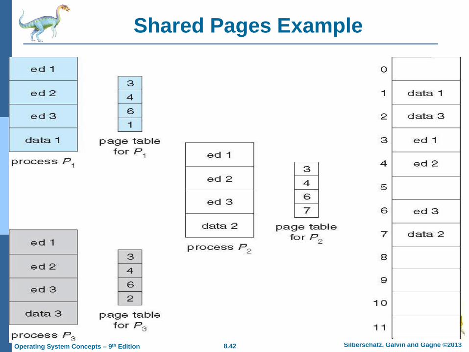
Shared Pages
Shared code
Also useful in time-sharing environments; e.g. many users using a text editor
One copy of read-only (reentrant) code is shared among processes
i.e., text editors, compilers, window systems, … etc
More than two processes can execute the same code at the same time
– Only one copy of the code (e.g., text editor) need be kept in memory
Similar to multiple threads sharing the same process space
Also useful for inter-process communication if sharing of read-write pages is
allowed.
Some OS implement shared-memory using shared pages.
Private code and data
Each process keeps a separate copy of the code and data
The pages for the private code and data can appear anywhere in the logical
address space
8.42 Silberschatz, Galvin and Gagne ©2013 Operating System Concepts – 9th Edition
Shared Pages Example

8.43 Silberschatz, Galvin and Gagne ©2013 Operating System Concepts – 9th Edition
Structure of the Page Table
Memory structures for paging can get huge using straight-forward methods
Consider a 32-bit logical address space as on modern computers
Page size of 4 KB (212)
Page table would have 1 million entries (232 / 212); number of pages
If each entry is 4 bytes
Then each process may need up to 4 MB of physical address space to
store its page table alone
– Very costly to store in main memory
– Do not want to allocate the page table contiguously in main memory
Solutions:
Hierarchical Paging
Hashed Page Tables
Inverted Page Tables
8.44 Silberschatz, Galvin and Gagne ©2013 Operating System Concepts – 9th Edition
Hierarchical Page Tables
Two-Level Paging Algorithm
The page table itself is also paged
Break up the logical address space into multiple page tables
A simple technique is a two-level page table
We then page the page table
8.45 Silberschatz, Galvin and Gagne ©2013 Operating System Concepts – 9th Edition
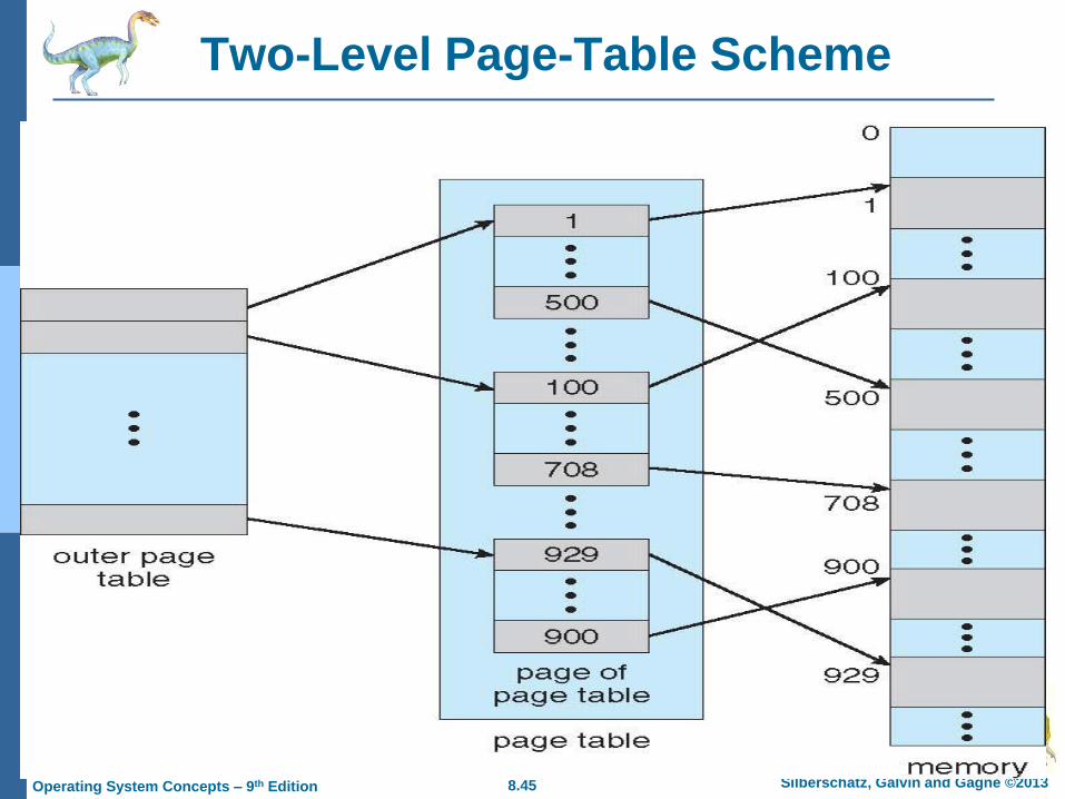
Two-Level Page-Table Scheme
8.46 Silberschatz, Galvin and Gagne ©2013 Operating System Concepts – 9th Edition
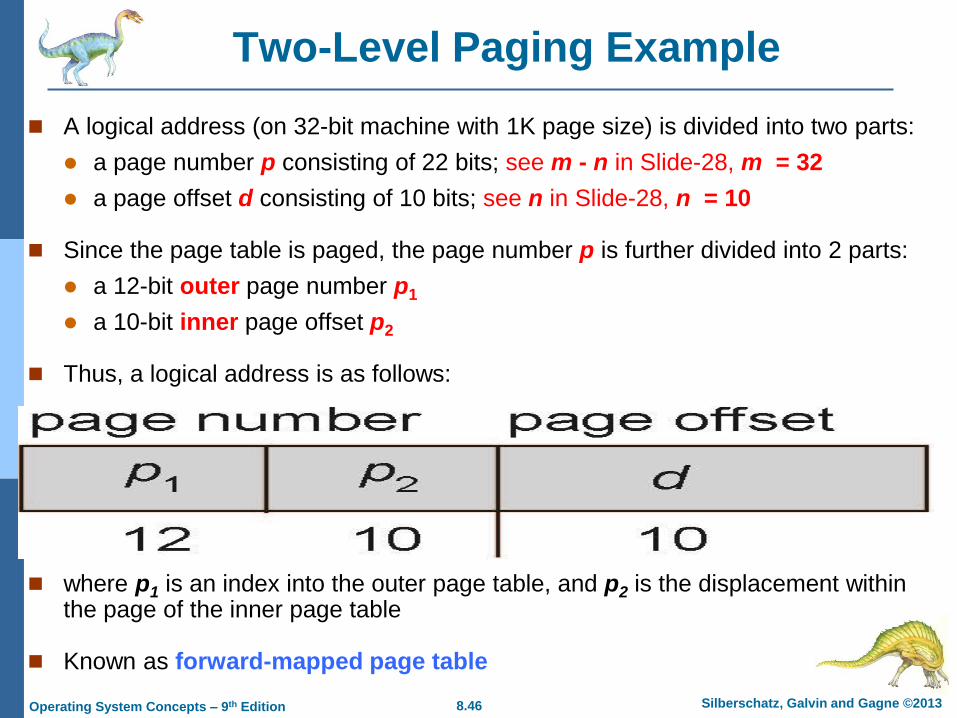
Two-Level Paging Example
A logical address (on 32-bit machine with 1K page size) is divided into two parts:
a page number p consisting of 22 bits; see m - n in Slide-28, m = 32
a page offset d consisting of 10 bits; see n in Slide-28, n = 10
Since the page table is paged, the page number p is further divided into 2 parts:
a 12-bit outer page number p1
a 10-bit inner page offset p2
Thus, a logical address is as follows:
where p1 is an index into the outer page table, and p2 is the displacement within the page of the inner page table
Known as forward-mapped page table
8.47 Silberschatz, Galvin and Gagne ©2013 Operating System Concepts – 9th Edition
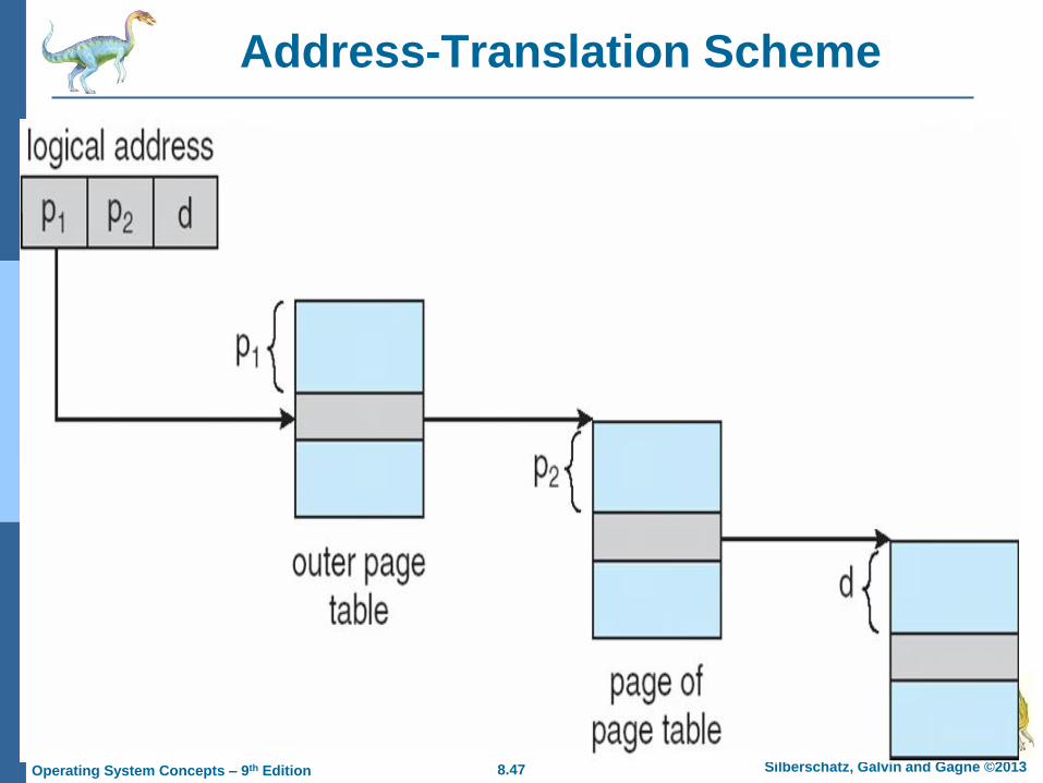
Address-Translation Scheme
8.48 Silberschatz, Galvin and Gagne ©2013 Operating System Concepts – 9th Edition
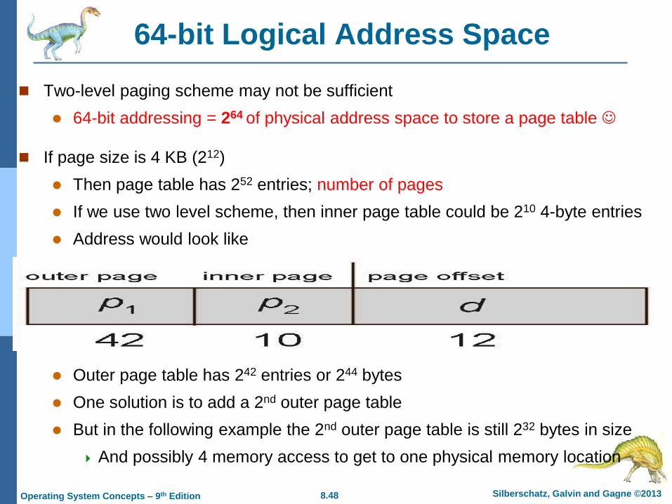
64-bit Logical Address Space
Two-level paging scheme may not be sufficient
64-bit addressing = 264 of physical address space to store a page table
If page size is 4 KB (212)
Then page table has 252 entries; number of pages
If we use two level scheme, then inner page table could be 210 4-byte entries
Address would look like
Outer page table has 242 entries or 244 bytes
One solution is to add a 2nd outer page table
But in the following example the 2nd outer page table is still 232 bytes in size
And possibly 4 memory access to get to one physical memory location

8.49 Silberschatz, Galvin and Gagne ©2013 Operating System Concepts – 9th Edition
Three-level Paging Scheme

8.50 Silberschatz, Galvin and Gagne ©2013 Operating System Concepts – 9th Edition
Hashed Page Tables
Common in address spaces > 32 bits
The virtual page number (the hash value) is hashed into a page table
Each entry in table is a linked list of elements hashing to the same location
For collision handling
Each element contains: (1) the virtual page number p, (2) the value of the
mapped page frame f, and (3) a pointer to the next element e
Algorithm: Virtual page numbers are compared in this list searching for a match
If a match is found, the corresponding physical frame is extracted
Variation for 64-bit addresses is clustered page tables
Similar to hashed but each entry refers to several pages (such as 16) rather
than 1
Especially useful for sparse address spaces (where memory references are
non-contiguous and scattered)

8.51 Silberschatz, Galvin and Gagne ©2013 Operating System Concepts – 9th Edition
Hashed Page Table

8.52 Silberschatz, Galvin and Gagne ©2013 Operating System Concepts – 9th Edition
Inverted Page Table
Normally, each process has a page table which keeps track of all its logical pages
and its physical pages (the frames)
What if the table contains millions of entries…? Too costly
Solution: use an inverted page table
It contains one entry for each real page of memory; i.e., a frame
Each entry consists of the virtual address of the page stored in that real
memory location, with information about the process that owns that page
Thus: only one page table is in the system; having only one entry or each frame
Decreases memory needed to store each page table, but increases time needed
to search the table when a page reference occurs; whole table may be searched
Use hash table to limit the search to one — or at most a few — page-table entries
TLB can accelerate access
But how to implement shared memory?
One mapping of a virtual address to the shared physical address

8.53 Silberschatz, Galvin and Gagne ©2013 Operating System Concepts – 9th Edition
Inverted Page Table Architecture

8.54 Silberschatz, Galvin and Gagne ©2013 Operating System Concepts – 9th Edition
Oracle SPARC Solaris
Consider modern, 64-bit operating system example with tightly integrated HW
Goals are efficiency, low overhead
Based on hashing, but more complex
Two hash tables
One kernel and one for all user processes
Each maps memory addresses from virtual to physical memory
Each entry represents a contiguous area of mapped virtual memory,
More efficient than having a separate hash-table entry for each page
Each entry has base address and span (indicating the number of pages the
entry represents)
8.55 Silberschatz, Galvin and Gagne ©2013 Operating System Concepts – 9th Edition
Oracle SPARC Solaris
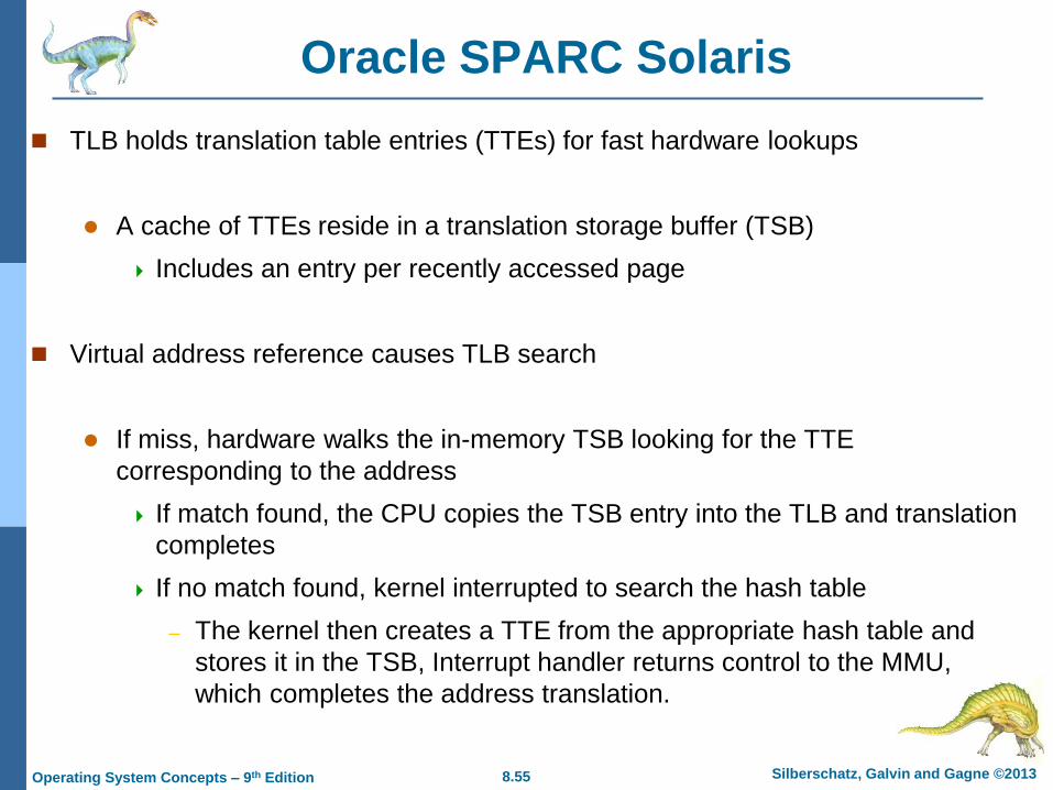
TLB holds translation table entries (TTEs) for fast hardware lookups
A cache of TTEs reside in a translation storage buffer (TSB)
Includes an entry per recently accessed page
Virtual address reference causes TLB search
If miss, hardware walks the in-memory TSB looking for the TTE
corresponding to the address
If match found, the CPU copies the TSB entry into the TLB and translation
completes
If no match found, kernel interrupted to search the hash table
– The kernel then creates a TTE from the appropriate hash table and
stores it in the TSB, Interrupt handler returns control to the MMU,
which completes the address translation.

8.56 Silberschatz, Galvin and Gagne ©2013 Operating System Concepts – 9th Edition
Intel IA-32 Page Address Extensions
32-bit address limits led Intel to create page address extension (PAE), allowing 32-bit
apps access to more than 4GB of memory space
Paging went to a 3-level scheme
Top two bits refer to a page directory pointer table
Page-directory and page-table entries moved to 64-bits in size
Net effect is increasing address space to 36 bits – 64GB of physical memory
8.57 Silberschatz, Galvin and Gagne ©2013 Operating System Concepts – 9th Edition
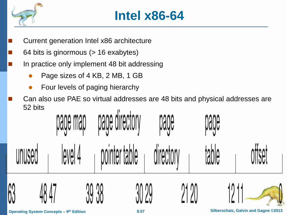
Intel x86-64
Current generation Intel x86 architecture
64 bits is ginormous (> 16 exabytes)
In practice only implement 48 bit addressing
Page sizes of 4 KB, 2 MB, 1 GB
Four levels of paging hierarchy
Can also use PAE so virtual addresses are 48 bits and physical addresses are
52 bits
8.58 Silberschatz, Galvin and Gagne ©2013 Operating System Concepts – 9th Edition
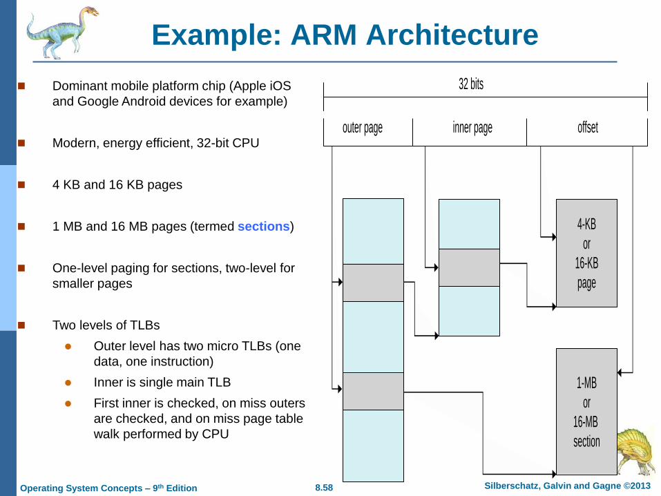
Example: ARM Architecture
Dominant mobile platform chip (Apple iOS
and Google Android devices for example)
Modern, energy efficient, 32-bit CPU
4 KB and 16 KB pages
1 MB and 16 MB pages (termed sections)
One-level paging for sections, two-level for
smaller pages
Two levels of TLBs
Outer level has two micro TLBs (one
data, one instruction)
Inner is single main TLB
First inner is checked, on miss outers
are checked, and on miss page table
walk performed by CPU
outer page inner page offset
4-KB
or
16-KB
page
1-MB
or
16-MB
section
32 bits

Silberschatz, Galvin and Gagne ©2013 Operating System Concepts – 9th Edition
End of Chapter 8

8.60 Silberschatz, Galvin and Gagne ©2013 Operating System Concepts – 9th Edition
Segmentation
Memory-management scheme that supports user view of memory
A program is a collection of segments
A segment is a logical unit such as:
main program
procedure
function
method
object
local variables, global variables
common block
stack
symbol table
arrays

8.61 Silberschatz, Galvin and Gagne ©2013 Operating System Concepts – 9th Edition
User’s View of a Program

8.62 Silberschatz, Galvin and Gagne ©2013 Operating System Concepts – 9th Edition
Logical View of Segmentation
1
3
2
4
1
4
2
3
user space physical memory space

8.63 Silberschatz, Galvin and Gagne ©2013 Operating System Concepts – 9th Edition
Segmentation Architecture
Logical address consists of a two tuple:
<segment-number, offset>,
Segment table – maps two-dimensional physical addresses; each
table entry has:
base – contains the starting physical address where the
segments reside in memory
limit – specifies the length of the segment
Segment-table base register (STBR) points to the segment
table’s location in memory
Segment-table length register (STLR) indicates number of
segments used by a program;
segment number s is legal if s < STLR

8.64 Silberschatz, Galvin and Gagne ©2013 Operating System Concepts – 9th Edition
Segmentation Architecture (Cont.)
Protection
With each entry in segment table associate:
validation bit = 0 illegal segment
read/write/execute privileges
Protection bits associated with segments; code sharing
occurs at segment level
Since segments vary in length, memory allocation is a
dynamic storage-allocation problem
A segmentation example is shown in the following diagram

8.65 Silberschatz, Galvin and Gagne ©2013 Operating System Concepts – 9th Edition
Segmentation Hardware

8.66 Silberschatz, Galvin and Gagne ©2013 Operating System Concepts – 9th Edition
Example: The Intel 32 and 64-bit Architectures
Dominant industry chips
Pentium CPUs are 32-bit and called IA-32 architecture
Current Intel CPUs are 64-bit and called IA-64 architecture
Many variations in the chips, cover the main ideas here

8.67 Silberschatz, Galvin and Gagne ©2013 Operating System Concepts – 9th Edition
Example: The Intel IA-32 Architecture
Supports both segmentation and segmentation with paging
Each segment can be 4 GB
Up to 16 K segments per process
Divided into two partitions
First partition of up to 8 K segments are private to
process (kept in local descriptor table (LDT))
Second partition of up to 8K segments shared among all
processes (kept in global descriptor table (GDT))

8.68 Silberschatz, Galvin and Gagne ©2013 Operating System Concepts – 9th Edition
Example: The Intel IA-32 Architecture (Cont.)
CPU generates logical address
Selector given to segmentation unit
Which produces linear addresses
Linear address given to paging unit
Which generates physical address in main memory
Paging units form equivalent of MMU
Pages sizes can be 4 KB or 4 MB

8.69 Silberschatz, Galvin and Gagne ©2013 Operating System Concepts – 9th Edition
Logical to Physical Address Translation in IA-32

8.70 Silberschatz, Galvin and Gagne ©2013 Operating System Concepts – 9th Edition
Intel IA-32 Segmentation

8.71 Silberschatz, Galvin and Gagne ©2013 Operating System Concepts – 9th Edition
Intel IA-32 Paging Architecture