Embed Size (px)
Citation preview
Chapter 8 Plane Electromagnetic Waves
Plane waves in perfect dielectric
Plane waves in conducting media
Polarizations of plane waves Normal incidence on a planar surface
Plane waves in arbitrary directions
Oblique incidence at boundary
Plane waves in anisotropic media

1. Wave Equations
2. Plane Waves in Perfect Dielectric
3. Plane Waves in Conducting Media
4. Polarizations of Plane Waves
5. Normal Incidence on A Planar Surface
6. Normal Incidence at Multiple Boundaries
7. Plane Waves in Arbitrary Directions
8. Oblique Incidence at Boundary between Perfect Dielectrics
9. Null and Total Reflections
10. Oblique Incidence at Conducting Boundary
11. Oblique Incidence at Perfect Conducting Boundary
12. Plane Waves in Plasma
13. Plane Waves in Ferrite

1. Wave Equations
In infinite, linear, homogeneous, isotropic media, a time-varying
electromagnetic field satisfies the following equations:
),(),(
),(
),(1),(),(
),(
2
22
2
22
tt
tt
tt
t
t
tt
rJrH
rH
rrJrE
rE
which are called inhomogeneous wave equations,and
),(),(),( ttt rErJrJ
where is the impressed
source.
),( trJ

t
)( E
In a region without impressed source, J ' = 0. If the medium is a
perfect dielectric, then, = 0 . In this case, the conduction current is
zero, and = 0. The above equation becomes
0),(
),(
0),(
),(
2
22
2
22
t
tt
t
tt
rHrH
rErE
Which are called homogeneous wave equations.
To investigate the propagation of plane waves, we first solve the
homogeneous wave equations.
The relationship between the charge density (r, t) and the conduction
current is ),( trE

For a sinusoidal electromagnetic field, the above equation becomes
0)()(
0)()(22
22
rHrH
rErE
k
k
which are called homogeneous vector Helmholtz equations, and here
k
In rectangular coordinate system, we have
0)()(
0)()(
0)()(
22
22
22
rr
rr
rr
zz
yy
xx
EkE
EkE
EkE
0)()(
0)()(
0)()(
22
22
22
rr
rr
rr
zz
yy
xx
HkH
HkH
HkH
which are called homogeneous scalar Helmholtz equations.
All of these equations have the same form, and the solutions
are similar.

In a rectangular coordinate system, if the field depends on one v
ariable only, the field cannot have a component along the axis of this v
ariable.
If the field is related to the variable z only, we can show
0 zz HE
z
H
z
H
y
H
x
H
z
E
z
E
y
E
x
E
zzyx
zzyx
H
E
Since the field is independent of the variables x and y, we have

Due to , from the above equations we obtai
n
0 ,0 HE
0
z
H
z
E zz
Considering
02
2
2
2
2
2
2
22
z
H
z
H
y
H
x
HH zzzz
z
02
2
2
2
2
2
2
22
z
E
z
E
y
E
x
EE zzzz
z
Substituting that into Helmholtz equations:
0)()( 22 rr zz EkE
0)()( 22 rr zz HkH
0 zz HEWe find

2. Plane Waves in Perfect Dielectric
In a region without impressed source in a perfect dielectric, a s
inusoidal electromagnetic field satisfies the following homogeneous
vector Helmholtz equation
0)()(
0)()(22
22
rHrH
rErE
k
k
If the electric field intensity E is related to the variable z only,
and independent of the variables x and y, then the electric field has
no z-component.
Let , then the magnetic field intensity H is xxEeE
)(jj
xxEeEH
xxx )(j
])[(j
eee xxx EEE
Where .k

z
E
z
E
y
E
x
EE x
zx
zx
yx
xx
eeeeDue to
z
EH x
y
jyy
xy H
z
EeeH
jWe have
From last section, we know that each component of the electric fiel
d intensity satisfies the homogeneous scalar Helmholtz equation. Cons
idering , we have0
y
E
x
E xx
0d
d 22
2
xx Ek
z
E
which is an ordinary differential equation of second order, and the
general solution iskz
xkz
xx EEE j0
j0 ee
The first term stands for a wave traveling along the positive
direction of the z-axis, while the second term leads to the opposite .

Here only the wave traveling along with the positive direction of
z-axis is consideredkz
xx EzE j0e)(
where Ex0 is the effective value of the electric field intensity at z = 0 .
) sin(2),( 0 kztEtzE xx The instantaneous value is),( tzEx
An illustration of the
electric field intensity varying
over space at different times
is shown in the left figure.
Ez(z, t)
zO
2
2
3
t1 = 042
Tt
23
Tt
The wave is traveling along
the positive z-direction.

where t accounts for phase change over time, and kz over space.
The surface made up of all points with the same space phase is calle
d the wave front.
Here the plane z = 0 is a wave front, and this electromagnetic
wave is called a plane wave.
Since Ex(z) is independent of the x
and y coordinates, the field intensity
is constant on the wave front. Hence,
this plane wave is called a uniform
plane wave.
) sin(2),( 0 kztEtzE xx

The time interval during which the time phase (t) is changed by 2
is called the period, and it is denoted as T. The number of periods in
one second is called the frequency, and it is denoted as f.
Since , we havef
T1π2
π2T
The distance over which the space phase factor (kr) is changed by 2
is called the wavelength, and it is denoted as .
Since , we
have
π2kk
π2
The frequency describes the rate at which an electromagnetic wave
varies with time, while the wavelength gives the interval in space for
the wave to repeat itself.
And we have π2
k
The constant k stands for the phase variation per unit length, and it
is called the phase constant, and the constant k gives the numbers of
full waves per unit length. Thus k is also called the wave number.

The speed of phase variation vp can be found from the locus of a
point with the same phase angle. Let , and nothing tha
t
, then the phase velocity vp is
const kzt
0dd zkt
kt
zv
d
dp
Considering , we have k
cc
rrrr00
11
Consider the relative permittivities of all media with , and with
relative permeability . The phase velocity of a uniform plane wave i
n a perfect dielectric is usually less than the velocity of light in vacuum.
1r
1r
In a perfect dielectric, the phase velocity is governed by the
property of the medium.
1
p k
v
It is possible to have . Therefore , the phase velocity must
not be the energy velocity.
cv p

fv p From the above results, we find
The frequency of a plane wave depends on the source, and it is
always the same as that of the source in a linear medium. However,
the phase velocity is related to the property of the medium, and hence
the wavelength is related to the property of the medium.
rr
0
rr00
p 1
ff
vWe find
where00
0
1
f
where 0 is the wavelength of the plane wave with frequency f in vacuum.
Since , , and . Namely, the wavelength of a plane
wave in a medium is less than that in vacuum. This phenomenon may
be called the shrinkage of wavelength.
0 1r 1r

z
kzy
kzxy HEH j
0j
0 ee
Using , we findz
EH x
y
j
00 xy EH
where
In perfect dielectrics, the electric field and the magnetic field of a
uniform plane wave are in phase, and both have the same spatial
dependence, but the amplitudes are constant.
The left figure shows the
variation of the electric field
and the magnetic field in space
at t = 0.Hy
Ex

The ratio of the amplitude of electric field intensity to that of
magnetic field intensity is called the intrinsic impedance, and is
denoted as Z as given by
y
x
H
EZ
The intrinsic impedance is a real number.
In vacuum, the intrinsic impedance is denoted as Z0
Ω π120Ω3770
00
Z
The above relationship between the electric field intensity and
the magnetic field intensity can be written in vector form as follows:
xzy ZEeH
1
zyx Z eHE Or
Ex
Hy
z

The electric field and the magnetic field are transverse with
respect to the direction of propagation and the wave is called a
transverse electromagnetic wave, or TEM wave.
A uniform plane wave is a TEM wave. Only non-uniform waves
can be non-TEM waves, and TEM waves are not necessarily plane
waves.
From the electric field intensity and the magnetic field intensity
found, we can find the complex energy flow density vector Sc as
20
20*
c yzx
zyx ZHZ
EeeHES
The complex energy flow density vector is real, while the
imaginary part is zero. It means that the energy is traveling in
the positive direction only,
We will encounter non-TEM wave that has the electric or the
magnetic field component in the direction of propagation.

We construct a cylinder of long l and cross-section A along the
direction of energy flow, as shown in the figure.
l
S A
Suppose the distribution of the energy is
uniform in the cylinder. The average value
of the energy density is wav , and that of the
energy flow density is Sav.
t
lAw
t
lAwAS av
avav
Obviously, the ratio stands for the displacement of the energy in tim
e t, and it is called the energy velocity, denoted as ve. We obtaint
l
av
ave w
Sv
lAwAtS avav
If all energy in the cylinder flows across the area A in the time
interval t, then
Then the total energy in the cylinder is wav Al , and the total energy f
lowing across the cross-sectional area A per unit time is Sav A.

Considering and , we findZ
ES x
20
av 20eavav 2 xEww
pe
1vv
The wave front of a uniform plane wave is an infinite plane
and the amplitude of the field intensity is uniform on the wave front,
and the energy flow density is constant on the wave front. Thus this
uniform plane wave carries infinite energy. Apparently, an ideal
uniform plane wave does not exist in nature.
If the observer is very far away from the source, the wave front is v
ery large while the observer is limited to the local area, the wave can be
approximately considered as a uniform plane wave.
By spatial Fourier transform, a non-plane wave can be expressed
in terms of the sum of many plane waves, which proves to be useful
sometimes

Example. A uniform plane wave is propagating along with the
positive direction of the z-axis in vacuum, and the instantaneous
value of the electric field intensity is
V/m )π210π6sin(220) ,( 8 zttz xeE
Find: (a) The frequency and the wavelength.
(b) The complex vectors of the electric and the magnetic field
intensities.
(c) The complex energy flow density vector.
(d) The phase velocity and the energy velocity.
Solution: (a) The frequency is Hz 103π2
10π6
π28
8
f
m 1π2
π2π2
kThe wavelength is

V/m e20)( π2j zxz eE
(b) The electric field intensity is
A/m eπ6
11)( π2j
0
zyzZ
z eEeH
The magnetic field intensity is
2*c W/m
π3
10zeHES
(c) The energy flow density vector is
m/s 103 8ep
kvv
(d) The phase and energy velocities are

3. Plane Waves in Conducting Media
If , the first Maxwell’s equation
becomes EEH j
If let je
EH ej
Then the above equation can be rewritten as
where e is called the equivalent permittivity.
In this way, a sinusoidal electromagnetic field then satisfies the f
ollowing homogeneous vector Helmholtz equation:
0
0
e22
e22
HH
EE
E)j(j

)j(ec kLet
We obtain
0
02c
2
2c
2
HH
EE
k
k
If we let as before, and , then the solution of t
he equation is the same as that in the lossless case as long as k is repla
ced by kc, so that
xxE eE 0
y
E
x
E xx
zkxx
cEE j0e
Because kc is a complex number, we define
kkk jc
We find
112
2
k 11
2
2
k
zkzkxx EE j
0 ee
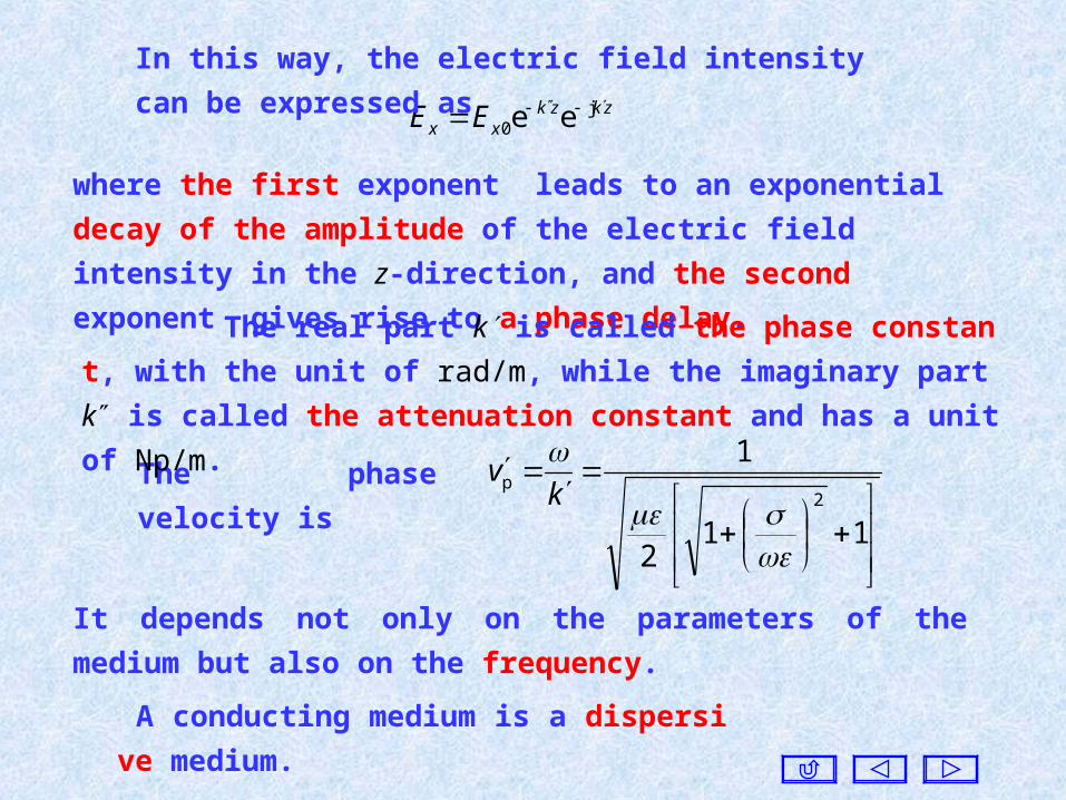
In this way, the electric field intensity can be expressed as
where the first exponent leads to an exponential decay of the amplitude
of the electric field intensity in the z-direction, and the second exponent
gives rise to a phase delay.
The phase velocity is
112
1
2p
k
v
It depends not only on the parameters of the medium but also on the
frequency.
A conducting medium is a dispersive medium.
The real part k is called the phase constant, with the unit of rad/m,
while the imaginary part k is called the attenuation constant and has a
unit of Np/m.

The wavelength is
112
π2π2
2
k
The wavelength is related to the properties of the medium, and it
has a nonlinear dependence on the frequency.
The intrinsic impedance is
ec
j1
Z
which is a complex number.
Since the intrinsic impedance is a complex number, and it leads
to a phase shift between electric field and the magnetic field.

The magnetic field intensity is
z
EH x
y
j zkxE
kcj
0c e
zkzk
xE j0 ee)j1(
The amplitude of the magnetic field intensity also decreases with z,
but the phase is different from that of the electric field intensity.
Ex
Hy
z
Since the electric and the magnetic
field intensities are not in phase, the
complex energy flow density vector has
non-zero real and imaginary parts.
This means that there is both energy
flow and energy exchange when a wave
propagates in a conductive medium.

Two special cases :
(a) If , as in an imperfect dielectric, the approximation
22
2
111
k
2k c
ZThen
The electric and the magnetic field intensities are essentially in
phase. There is still phase delay and attenuation in this case. The
attenuation constant is proportional to the conductivity .
(b) If , as in good conductors, we take
2
1

π2
fkk
f
Zπ
)j1(j
c Then
The electric and the magnetic field intensities are not in phase,
and the amplitudes show a rapid decay due to a large . In this case,
the electromagnetic wave cannot go deep into the medium, and it
only exists near the surface. This phenomenon is called the skin
effect.
The skin depth is the distance over which the field amplitude is
reduce by a factor of , mathematically determined frome
1
1ee k
fk π
11
The skin depth is inversely proportional to the square root of the
frequency f and the conductivity .

The skin depths at different frequencies for copper 4103f MHz 0.05 1
mm 29.8 0.066 0.00038
The skin depth deceases with increasing frequency.
The frequency for sets the
boundary between an imperfect diel
ectric and a conductor, and it is call
ed crossover frequency.
1
stands for the ratio of ampli
tude of the conduction current to tha
t of the displacement current.
In imperfect dielectrics the dis-
placement current dominates, while
the converse is true for a good cond
uctor.
Several crossover
frequencies for different
materials: Media Frequencies MHz
Dry Soil 2.6 (Short Wave)
Wet Soil 6.0 (Short Wave)
Pure Water 0.22 (Medium Wave)
Sea Water 890 (Super Short Wave)
Silicon 15103 (Microwave)
Germanium 11104 (Microwave)
Platinum
16.91016 (Light Wave)
Copper 104.41016 (Light Wave)

The attenuation of a plane wave is caused by the conductivity , r
esulting in power dissipation, and conductors are called lossy media.
Dielectrics without conductivity are called lossless media.
Besides conductor loss there are other losses due to dielectric polari
zation and magnetization. As a result, both permittivity and permeabil
ity are complex, so that and . j j
The imaginary part stands for dissipation, and they are called
dielectric loss and magnetic loss, respectively.
For non-ferromagnetic media, the magnetization loss can be
neglected.
For electromagnetic waves at lower frequencies, dielectric loss can
be neglected.

0z
Example. A uniform plane wave of frequency 5MHz is propagating
along the positive direction of the z-axis. The electric field intensity is in
the x-direction at , with an effective value of 100(V/m). If the region
is seawater, and the parameters are , find:
(a) The phase constant, the attenuation constant, the phase velocity, the
wavelength, the wave impedance, and the skin depth in seawater.
(b) The instantaneous values of the electric and the magnetic field inten
sities, and the complex energy flow density vector at z = 0.8m.
(S/m)4 ,1 ,80 rr
Solution: (a) π10 Hz105 76 f
11808010
π361
π10
4
97
The seawater can be considered as a good conductor, and the
phase constant k' and the attenuation constant k" are, respectively,
rad/m 89.8π fk Np/m 89.8π fk

m 707.0π2
k
The wavelength is
Ωπe)j1(2
ππ)j1( 4
πj
c f
ZThe intrinsic impedance is
m/s 1053.3 6p
kv
The phase velocity is
m112.0π
1
fThe skin depth is
V/m ee100)( j zkzkxz eE
(b) The complex vector of the electric field intensity is
)(1
)(c
zZ
z z EeH A/m ee100 j
c
zkzky Z
e
The complex vector of the magnetic field intensity is

The instantaneous values of the electric and the magnetic field
intensities at z = 0.8m as
)8.089.8π10sin(e2100) ,8.0( 78.089.8 tt xeE
)11.7π10sin(115.0 7x te
)70.7π10sin(0366.0),8.0( 7 tt yeH
The complex energy flow density vector as
24
πj62
*
c
2*
c W/me106644e100
zzzk
ZeeHES
The plane wave of frequency 5MHz is attenuated very fast in
seawater. Therefore it is impossible to communicate between two
submarines by using the direct wave in seawater.

The time-varying behavior of the direction of the electric field
intensity is called the polarization of the electromagnetic wave.
4. Polarizations of Plane Waves
Suppose the instantaneous value of the electric field intensity of
a plane wave is) sin() ,( m kztEtz xxx eE
Obviously, at a given point in space the locus of the tip of the electric
field intensity vector over time is a straight line parallel to the x-axis.
Hence, the wave is said to have a linear polarization.
The instantaneous value of the electric field intensity of another
plane wave of the same frequency is
) sin() ,( m kztEtz yyy eE
This is also a linearly polarized plane wave, but with the electric
field along the y-direction.

If the above two orthogonal, linearly polarized plane waves with
the same phase but different amplitudes coexist, then the
instantaneous value of the resultant electric field is
) ,() ,(),( 22 tzEtzEtzE yx ) sin(2m
2m kztEE yx
The time-variation of the magnitude of the resultant electric field
is still a sinusoidal function, and the tangent of the angle between
the field vector and the x-axis is
m
m
),(
),(tan
x
y
x
y
E
E
tzE
tzE
The polarization direction of the resultant
electric field is independent of time, and the
locus of the tip of the electric field intensity
vector over time is a straight line at an angle
of to the x-axis. Thus the resultant field is
still a linearly polarized wave.
Ey
Ex
Ey
x
O
Ey
Ex
E
y
x
O
Ey
Ex
E
y
x
O

If two orthogonal, linearly polarized plane waves of the same
phase but different amplitudes are combined, the resultant wave is still
a linearly polarized plane wave.
If the above two linearly polarized plane waves have a phase diff
erence of , but the same amplitude Em, i.e.2
π
) sin(),( m kztEtzx xeE
)2
π sin(),( m kztEtz yy eE ) cos(m kztEy e
Conversely, a linearly polarized plane wave can be resolved into
two orthogonal, linearly polarized plane waves of the same phase but
different amplitudes.
If the two plane waves have opposite phases and different
amplitudes, how about the resultant wave?

The direction of the resultant wave is at an angle of to the x-axis,
and
) (cot),(
),(tan kzt
tzE
tzE
x
y )] (2
πtan[ kzt
Then the instantaneous value of the resultant wave is
m22 ),(),() ,( EtzEtzEtzE yx
) (2
πkzta i.e.
At a given point z the angle is a function of time t. The direction of
the electric field intensity vector is rotating with time, but the magnitude
is unchanged. Therefore, the locus of the tip of the electric field intensity
vector is a circle, and it is called circular polarization.

The angle will be decreasing with increasing time t . When the
fingers of the left hand follow the rotating direction, the thumb points
to the propagation direction and it is called the left-hand circularly
polarized wave.
Ey
Ex
E
y
x
O
Left
Right
z
y
x
O
) (2
πkzt
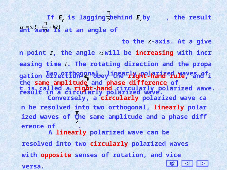
Two orthogonal, linearly polarized waves of the same amplitude
and phase difference of result in a circularly polarized wave. 2
π
A linearly polarized wave can be resolved into two circularly
polarized waves with opposite senses of rotation, and vice versa.
If Ey is lagging behind Ex by , the resultant wave is at an angle of
to the x-axis. At a given point z, the angle will be incr
easing with increasing time t. The rotating direction and the propagati
on direction ez obey the right-hand rule, and it is called a right-hand ci
rcularly polarized wave.
2
π
)2
π( kzt
2
π
Conversely, a circularly polarized wave can be resolved into two
orthogonal, linearly polarized waves of the same amplitude and a pha
se difference of .

If two orthogonal, linearly polarized plane waves Ex and Ey have
different amplitudes and phases
)sin(),(
)sin(),(
m
m
kztEtz
kztEtz
yyy
xxx
eE
eE
The components Ex and Ey of the resultant wave satisfy the follo
wing equation
2
mm
2
m
2
m
sincos2
)()( yx
yx
y
y
x
x
EE
EE
E
E
E
E
which describes an ellipse. At a given
point z, the locus of the tip of the
resultant wave vector over time is an
ellipse, and it is called an elliptically
polarized wave.
y
x
Ex '
y '
Ey m
Ex m

The linearly and the circularly polarized waves can both be
considered as the special cases of the elliptically polarized wave.
Since all polarized waves can be resolved into linearly polarized
waves, only the propagation of linearly polarized wave will be
discussed. The propagation behavior of an electromagnetic wave is a useful
property with many practical applications.
If < 0 , Ey lags behind Ex , and the resultant wave vector is rotated
in the counter-clockwise direction. It is a right-hand elliptically polari
zed wave.
If > 0 , then the resultant wave vector is rotated in the
clockwise direction, and it is a left-hand elliptically polarized wave.
Since a circularly polarized electromagnetic wave is less attenuated
by rain, it is used in all-weather radar.
Stereoscopic film is taken by using two cameras with two orthog
onally polarized lenses. Hence, the viewer has to wear a pair of ortho
gonally polarized glasses to be able to see the three-dimensional effec
t.
some microwave devices use the polarization of the wave to
achieve special functions, as found in ferrite circulators, ferrite
isolators, and others.
In mobile satellite communications and globe positioning systems,
because the position of the satellite changes with time, circularly
polarized waves should be used.
In wireless communication systems, the polarization of the
receiving antenna must be compatible with that of the wave to be
received.

111 222
z
x
y
Consider an infinite planar boundary between two homogeneous
media with the parameters of the media and . )( 111 )( 222
Let the boundary coincides with
the plane z = 0. As an x-directed,
linearly polarized plane wave is
normally incident on the boundary
from medium ①, a reflected and a
transmitted wave are produced at
the boundary. S t
txE
tyH
S r
rxE
ryH
S i
ixE
iyH
Since the tangential components of the electric field intensities
must be continuous at any boundary, the sum of the tangential
components of the electric field intensities of the incident and the
reflected waves is equal to that of the transmitted wave.
5. Normal Incidence on A Planar Surface

The polarization cannot be changed during the reflection and
the transmission of a linearly polarized wave.
Assume that the electric field intensities of the incident, the
reflected, and the transmitted waves are given in the figure, and they
can be expressed as follows:
111 222
z
x
y
S r
rxE
ryH
Reflected wave zk
xx EE 1cjr0
r e
S i
ixE
iyH
zkxx EE c1ji
0i eIncident wave
S t
txE
tyH
zkxx EE 2cjt
0t eTransmitted wave
where , , are the amplitudes at the boundary, respectively.i0xE r
0xE t0xE

The magnetic field intensities as
zkxy Z
EH 1cj
1c
i0i eIncident wave
zkxy Z
EH 1cj
1c
r0r e
Reflected wave
zkxy Z
EH c2j
2c
t0t eTransmitted wave
The tangential components of electric field intensities must be
continuous at any boundary. Consider there is no surface current at
the boundary with the limited conductivity. Hence the tangential
components of the magnetic field intensities are also continuous at the
boundary z = 0.
2c
t0
1c
r0
1c
i0
Z
E
Z
E
Z
E xxx t0
r0
i0 xxx EEE We have

The ratio of the electric field components of the reflected wave to
that of the incident wave at the boundary is defined as the reflection
coefficient, denoted as R. The ratio of the electric field components of
the transmitted wave to that of the incident wave at the boundary is
called the transmission coefficient, denoted as T.
In medium ①, the resultant electric and magnetic field intensities
are)e e()( 1c1c jji
0zkzk
xx REzE )e e()( c1c1 jj
1c
i0 zkzkx
y RZ
EzH
c12c
1c2ci0
r0 ZZ
ZZEE xx
1c2c
2ci0
t0
2
ZZ
ZEE xx
We find
1c2c
1c2ci0
r0
ZZ
ZZ
E
ER
x
x
c1c2
2ci0
t0 2
ZZ
Z
E
ET
x
x
We obtain

(a) If medium ① is a perfect dielectric and medium ② is a p
erfect electric conductor , the intrinsic impedances of the media,
are respectively,
)0( 1
)( 2
11
1c1 ZZ
Two special boundaries as follows:
1R 0TWe find
All of the electromagnetic energy is reflected by the boundary, and
no energy enters into medium ②. This case is called total reflection.
The refection coefficient R = 1 implies that at the boundary
so that the electric fields of the reflected and the incident waves have the
same amplitude but opposite phase, resulting in a total electric field that
is zero at the boundary.
i0
r0 xx EE
0j
c2
Z

The propagation constant for medium ① is , and in
medium ① the complex vector of the resultant electric field is
11c kk )(zEx
)ee()( 11 jji0
zkzkxx EzE zkEx 1
i0 sin2j 2
πj
1i0 esin2
zkEx
The instantaneous value is
)2
π sin(sin22),( 1
i0 tzkEtzE xx tzkEx cossin22 1
i0
At the amplitude of the electric field is always the
largest at any time. 4
)12( 1 nz
In medium ① the phase of the resultant electric field is dependent
on time only, and the amplitude has a sinusoidal dependence on z. when
the electric field is zero all the time. 21
nz )2 1, 0,( n
This means that the spatial phase of the resultant wave is fixed, and
the amplitudes vary in a proportionate manner. This plane wave is not
traveling, but stays at a fixed location with the field intensities varying
periodically as time progresses. It is called a standing wave.

Ex 0>0
z
1
O
1 = 0 2 =
42
Tt
24
Tt
Tt8
33
t1 = 0
21
Ex 0>0t1 = 0
1
21
z
1 = 0 2 =
O
The location at which the amplitude is always zero are called wave
node, while the location at which the amplitude is always maximum ar
e called wave loop.
The plane wave in an open perfect dielectric as discussed
previously is called a traveling wave, as opposed to a standing wave.
The phase of a traveling wave is progressing in the propagation
direction, while that of a standing wave does not move in space.
Ex 0>0
1
21
z
1 = 0 2 =
O42
Tt
Ex 0>0
1
21
z
1 = 0 2 =
O
Tt8
33
Ex 0>0
1
21
z
1 = 0 2 =
O
24
Tt

zkZ
E
Z
EzH xzkzkx
y 11
i0jj
1
i0 cos
2)ee()( 11
The complex vector of the resultant magnetic field intensity
is
tzkZ
EtzH x
y sincos22
),( 11
i0
The instantaneous value is
The resultant magnetic field
is still a standing wave, but the
positions of the wave nodes and
the wave loops are opposite to
that of electric field.
Hy 0
z
1
O
1 = 0 2 =
y
01 t
Tt4
33
42
Tt

The electric field and the magnetic field have a phase difference
of . Hence, the real part of the energy flow density vector is zero,
and it has the imaginary part only. 2
π
In medium ① immediately to the left of the boundary at z = 0, th
e resultant magnetic field is , but inside medium ② it is
. Therefore, in this case the tangential components of the ma
gnetic field intensities are discontinuous at the boundary. There exis
ts a surface current JS at the boundary, with a surface current densi
ty given by
1
i02
)0(Z
EH x
y 0)0(t yH
1
i0
n
2)(
Z
EH x
xyzyS eHeeJ
It means that there is no energy flow in space, and the energy is
converted between the electric field and the magnetic field.

(b) If medium ① is a perfect dielectric = 0 and medium ② is a
conductor with finite conductivity. The intrinsic impedance and the p
ropagation constant of medium ① are given by
11
11c ZZ
1111c kk
The reflection coefficient isj
12c
12c e|| RZZ
ZZR
where is the amplitude of R, and is its argument.|| R
If , which corresponds to a maximum
for the electric field, located at , the magnitude of the
electric field intensity is given by
π22 1 nzk ) ,2 ,1 0,( n
1)π42
(
nz
|)|1(|| i0max REE xx
)e||e()( )(jji0
11 zkzkxx REzE zkzk
x RE 11 j)2(ji0 e)e||1(
The resultant electric field intensity in medium ① is

If , which corresponds to
a minimum for the electric field at the locations ,
the magnitude of the electric field intensity is given by
π)12(2 1 nzk ) ,2 ,1 0,( n
1)π44
1
2(
n
z
|)|1(|| i0min REE xx
O
1
z21
maxE
minE
The ratio of the maximum value to the minimum value for the
electric field intensity is called the standing wave ratio S, i.e.
||1
||1
||
||
min
max
R
R
E
ES
Since , the amplitude of
the electric field lies
in .
The pattern of the standing wave is
shown in the left figure.
1||0 Ri02||0 xx EE
The distance between two maxima
(or minima) on a standing wave is .2
1

If two media are perfect dielectric, the maximum point is at the
boundary when , and if the minimum point is at the
boundary . 12 ZZ 12 ZZ
In this case, this standing wave is different from the full standing
wave, and its pattern can be thought to be made up of a full standing
wave together with a traveling wave.
||1
||1
||
||
min
max
R
R
E
ES
For the case of total reflection, .
SR ,1||
If , then , corresponding to the absence of
the reflected wave. This boundary without reflection is called a
matched boundary.
12c ZZ 1 ,0|| SR
S1Hence, the range of the standing wave ratio
is .

Example. Two media with the parameters, , ;
, are joined at a planar boundary. A right-hand circularly
polarized plane wave is incident on the boundary from medium ①.
Find the reflected and the transmitted waves and their polarizations.
02 9 01 01 4
02
111 222
z
x
y
S t
txE
tyE
S r
rxE
ryE
S i
ixE
iyE
zkyxE 1j
0i e)j( eeE
zkyxRE 1j
0r e)j( eeE zk
yxTE 3j0
t e)j( eeE
Since the incident wave is a right-
hand circularly polarized wave, the
incident wave can be expressed as
Solution: Select rectangular
coordinate system, and let the
boundary be placed at the plane 0z
The reflected wave and the transmitted wave are, respectively,

The reflection and the transmission coefficients are
5
1
2
1
3
1
2
1
3
1
12
12
ZZ
ZZR
5
4
2
1
3
1
3
12
2
12
2
ZZ
ZT
Because the y-components of the reflected and the transmitted
waves are still lagging behind the x-components, but the
propagating direction of the reflected wave is always is along the
negative z-direction, and it becomes left-hand circularly polarized
wave. The propagating direction of the transmitted wave is in the
positive z-direction, and it is still the right-hand circularly polarized
wave.

6. Normal Incidence at Multiple Boundaries
As an example, consider a three-layer medium first.
Zc1 Zc2 Zc3
-l O z① ② ③
1xE
3xE
2xE
2xE
1xE
There are multiple reflections and transmissions between the
two boundaries.

Based on the solution of one-dimensional wave equation, we can co
nsider there are two waves in medium ① or ② only, one is propagat
ing along with the positive z-direction denoted as and , and anot
her is in the negative z-direction denoted as and . In medium ③
there is only one wave propagating along the positive z-direction.
1xE
3xE
2xE
2xE
1xE
lzEzE lzkxx e)( )(j101
1c
lzEzE lzkxx e)( )(j101
1c
0 e)( 2cj202 zlEzE zk
xx
zEzE zkxx 0 e)( 3cj
303
0 e)( c2j202 zlEzE zk
xx
Hence, the electric fields in the media can be expressed as
follows:
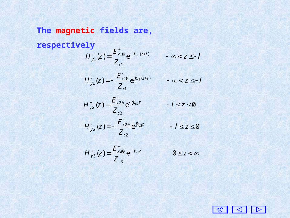
lzZ
EzH lzkx
y
e)( )(j
1c
101
1c
lzZ
EzH lzkx
y
e)( )(j
1c
101
1c
0 e)( 2cj
2c
202
zl
Z
EzH zkx
y
0 e)( 2cj
2c
202
zl
Z
EzH zkx
y
zZ
EzH zkx
y 0 e)( c3j
3c
303
The magnetic fields are, respectively

)0(
)( ee
302020
j20
j201010
2c2c
zEEE
lzEEEE
xxx
lkx
lkxxx
Since the tangential components of the electric field intensities
must be continuous at z = 0 and z = l , we have
Because the tangential components of the magnetic field
intensities must be continuous at the two boundaries also, we have
)0(
)( ee
3
30
2c
20
2c
20
j
2c
20j
2c
20
1c
10
1c
10 2c2c
zZ
E
Z
E
Z
E
lzZ
E
Z
E
Z
E
Z
E
c
xxx
lkxlkxxx
The quantity is given, while , , , and are unknown,
which can be found from the four equations above.
10xE
30xE20xE
20xE10xE

If we only need to find the total reflection coefficient at the first
boundary, then using the input wave impedance, one can simplify
the process.
)(
)()(
2
2in zH
zEzZ
y
x
For an n-layered medium, since the incident wave is known, and
there is only a transmitted wave in the n-th layer, the total number of
unknowns are . The n-layered medium has boundaries, wit
h which we can construct equations.Therefore, all unknowns ca
n be determined.
)22( n
)1(2 n
)1( n
For the above example, the ratio of the resultant electric field t
o the resultant magnetic field at a point (z) in medium ② is defined
as the input wave impedance at the point, and it is denoted as Zin, gi
ven by

where2c3c
2c3c
20
2023 ZZ
ZZ
E
ER
x
x
The resultant magnetic field in medium ② can be expressed as
)ee()( c2c2 j23
j
2c
202
zkzkxy R
Z
EzH
zkZZ
zkZZZzZ
2cc3c2
2cc2c32cin tanj
tanj)(
We find
Since the resultant electric and magnetic fields should be
continuous at the boundary , we have
)(
)(
)(
in
2
1c
10
1c
10
21010
lZ
lE
Z
E
Z
E
lEEE
xxx
xxx
The resultant electric field in medium ② is
zkx
zkxx EEzE 2c2c j
20j
202 ee)( )ee( 2c2c j23
j20
zkzkx RE

10
10
x
x
E
ER
The total reflection coefficient at the first boundary is defined
lkZZ
lkZZZlZ
c23c2c
2c2c3c2cin tanj
tanj)(
where
For medium ①, media ② and ③ can be considered as one medi
um with the wave impedance Zin(l) . If the thickness and the parame
ters of medium ②, and the parameters of medium ③ are known, th
en the input wave impedance Zin(l) can be found.
The approach of input wave impedance is in fact similar to the
network method in circuit theory. The total effect of the media
needs to be considered collectively instead of the inside of the multi-
layered medium.
1cin
1cin
)(
)(
ZlZ
ZlZR

n-layered medium
First we calculate the input wave impedance toward the
right at the (n2)-th boundary, and then for the (n2)-th medium, t
he (n1)-th and the n-th media can be replaced by a medium with
wave impedance .
)2(in
nZ
)2(in
nZ
Zc1 Zc2 Zc3
(n-2) (n-1)(3)(2)(1)Zc(n-2) Zc(n-1) Zc n
)2(in
nZ(2)inZ)1(
inZ
Similarly, the input wave impedance toward the right at
each boundary can be found one by one from the right to the left.
Finally, we can find the total reflection coefficient.

Z1 ZnZ3Z2 Zn-1Zn-2
1)1(
in
1)1(
in
ZZ
ZZR
(1)inZ
Z1
)2(in
nZ
Z1 Z3Z2 Zn-2
)2(inZ
Z1 Z2
)3(inZ
Z3Z1 Z2

Example. The wave impedances of two perfect dielectrics are Z1
and Z2 , respectively. In order to eliminate the reflection, a piece of
perfect dielectric of the thickness of one-quarter wavelength (in the
middle dielectric) is inserted between the two dielectrics. Find the wave
impedance of the middle dielectric. Solution. First we calculate the input
wave impedance to the right at the first
boundary. Consider
4
l
Z1 Z Z2
②①
4
2
π2 lk
2
2
2in Z
Z
Z
ZZZ We find
To eliminate the reflection, is required, and we find1in ZZ
2
2
1 Z
ZZ
21ZZZ
The approach of input wave impedance is a kind of impedance
transform.

This transform is applicable for a certain frequency, resulting in
narrow-band operation.
In microwave circuits, transmission line of one quarter wavelength
is used to transform the impedance. In this case, it will extend the total
length of the transmission line, but the impedance match can be
realized.
The change of input wave impedance is the same as that of a
tangent function. The period of change is , and the sandwiched
dielectric with a thickness of one half-wavelength or integral times of
half-wavelength has no action of impedance transform. 。
We know that the input wave impedance is
lkZZ
lkZZZlZ
2c3c2c
2c2c3c2cin tanj
tanj)(

If the relative permittivity of a dielectric is equal to the relative
permeability so that r = r , the wave impedance will be equal to th
at of vacuum.
If this dielectric slab is used as a radom, it should have perfect p
erformance. However, the relative permittivity and the relative per
meability are usually not of the same order of magnitude. Recently,
a newly developed magnetic material can approximately meet this r
equirement.
When such a dielectric slab is placed in air, and a plane wave is
normally incident upon the surface of the slab, there will be no
reflection regardless of the slab thickness. In other words, for the
electromagnetic wave it is “transparent”.

7. Plane Waves in Arbitrary Directions
Suppose the propagating direction of a plane wave is eS , and it i
s perpendicular to the wave front of the plane wave as shown in the
figure.Let the distance between the origin
and the wave front be d, and the
electric field intensity at the origin
be E0 , then we can obtain the
electric field intensity at a point P0
on the wave front askdP j
00 e)( EE
z
yx
d
eS
P0
E0
Wave front
P(x, y, z)
r
If let P be a point on the wave front, and its coordinates are (x, y, z),
then the position vector r of the point P is
zyx zyx eeer

and reEE Sk j0e
If let ke Sk
Here k is called the wave vector, and its direction is the
propagating direction and the magnitude is equal to the
propagation constant k.
rkEE j0eThen
If the wave vector k makes an angle of , , with the x, y, z-axes,
respectively, then the propagating direction eS can be written as
coscoscos zyxS eeee
coscoscos kkk zyx eeek And the wave vector is
z
yx
d
eS
P0
E0
P(x, y, z)r
We have re Srd cos
which is the expression for a plane
wave traveling in an arbitrary
direction.

coskkx coskk y coskkz If let
zzyyxx kkk eeek
Then the wave vector k can be expressed as
The electric field intensity can be expressed at any point as
)(j0e
zkykxk zyx EE
)coscoscos(j0e
zyxk EEor
Since , should satisfy t
he following equation
1coscoscos 222 zyx kkk ,,
2222 kkkk zyx
Obviously, only two of are independent.zyx kkk ,,
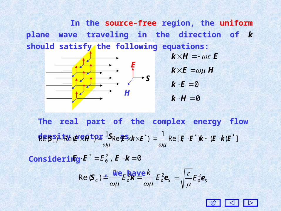
S
In the source-free region, the uniform plane wave traveling in
the direction of k should satisfy the following equations:
EHk
HEk
0Ek
0Hk
The real part of the complex energy flow density vector Sc as
)Re()Re( *c HES )Re(
1 *EkE
])()Re[(1 * *EkEkEE
SEk
E ekS 20
20c
1)Re(
SE e2
0
Considering , we have 0 ,20
* kEEE E
H
E

Example. In vacuum a plane wave is TEM wave, and the
electric field intensity is
zyxzyyx E 6.0)8.06.0(3.2 j
0 ee])5j2([ eeeE
Find out: (a) If it is a uniform plane wave. (b) The frequency and th
e wavelength of the plane wave. (c) The y-component of the electri
c field. (d) The polarization of the plane wave. 0yE
Where is a constant. 0yE
Solution: The electric field intensity is given as
)6.0j8.06.0(3.2 j0 e])5j2([ zyx
zyyx E eeeE
In view of this, the propagating path is in the xy-plane, and the wa
ve front is parallel to the z-axis. Because the amplitude of the field i
ntensity is related to the variable z, it is an inhomogeneous plane w
ave.

x
y
z
k
Wave front
m73.2π2
k
MHz110cv
f
3.28.06.03.2 22 kWe find
Due to , we obtain
.
0Ek 75.00 yE
The resultant field of the x-comp
onent and the y-component of the elec
tric field intensity is a linearly polariz
ed wave. Together with the z-compon
ent with the different phase and ampli
tude, they are combined into an ellipti
cally polarized wave. Since the compo
nent lags behind the component Ez, t
he resultant wave is a right-hand ellip
tically polarized wave.
(Ex + Ey)
(Ex+Ey +Ez)Ez
zyxzyyx E 6.0)8.06.0(3.2 j
0 ee])5j2([ eeeEFrom

1 1
2 2
x
z
y
Normal
8. Oblique Incidence at Boundary between Perfect Dielectrics
When a plane wave is incident upon a plane boundary, reflection an
d transmission will take place. Since the direction of the transmitted w
ave is different from that of the incident wave, this transmitted wave i
s called a refracted wave. The planes containing the incident ray, the r
eflected ray, the refracted ray and the normal to the boundary are call
ed the plane of incidence, the plane of reflection, the plane of refractio
n.
t
Refracted wave
Reflected wave
riIncident wave

(a) All of the incident ray, the reflected ray, and the refracted ra
y are in the same plane. (b) The angle of incidence i is equal to the a
ngle of reflection r . (c) The angle of incidence i and the angle of ref
raction t satisfy the following relationship:
1
2
t
i
sin
sin
k
k
The three conditions above are called Snell’s Law, and
111 k 222 k
Suppose the plane of incidence be in the xz-plane, then the electric
field intensity of the incident wave can be written as
)coscos(ji0
i ii1e zxk EE
)coscoscos(jr0
r rrr1e zyxk EE )coscoscos(jt0
t ttt2e zyxk EE
The reflected and the refracted waves can be expressed,
respectively, as

Since the tangential components of the resultant electric field
intensities must be continues at z = 0, giving
t)coscos(jr
0cosji
0 ]ee[ rr1i1 yxkxk EE tcoscos(jt
0 ]e[ tt2 yxk E
which holds for any x and y, thus the corresponding coefficients in
each exponent should be equal, so that
t2r1 coscos0 kk
t2r1i1 coscoscos kkk
We have , i.e. 0coscos tr
2
πtr
which states that the reflected ray and the refracted ray are in the xz-
plane.

ri 1
2
t
i
sin
sin
k
k
Snell’s law is used widely in practice. For example, the
bottom surfaces of stealth planes B2 and F117 are almost a flat
plane, so that the echo wave of the radar is reflected forward so
that a mono-static radar cannot receive it. The stealthy behavior of
the flights is therefore realized.
states that the phases of the
reflected and the refracted waves are varying along the boundary
in synchronism with the phase of the incident wave, and it is called
the condition for phase matching.
t2r1i1 coscoscos kkk
Considering , , , we have
ii 2
π tt 2
π rr 2
π

For the oblique incidence, the reflection and the
transmission coefficients are related to the polarization of the
incident wave.
The polarization of a parallel or perpendicular polarized wave
remains unchanged after reflection and refraction.
i r
t
1 1
2 2
E i
E t
E r
H i H r
H t
z
x
O
Parallel
i r
t
1 12 2
E i
E t
E r
H i H r
H t
z
xO
Perpendicular
The plane wave whose direction of electric field is parallel to the
plane of incidence as parallel polarized wave, and that being
perpendicular to the plane of incidence is called perpendicular
polarized wave,

The reflection and the transmission coefficients
r1i1 sinjr
r0
sinji
i0 ecosecos xkxk EE t2 sinj
tt0 ecos xkE
For the parallel polarized wave, we have
Considering the condition for phase matching, we obtain
tt0r
r0i
i0 coscoscos EEE
From the boundary condition of the tangential components of the
magnetic fields to be continuous at the boundary, similarly we find
2
t0
1
r0
1
i0
Z
E
Z
E
Z
E
Based on the definitions of the reflection and the transmission coef
ficients at the boundary, we find the reflection coefficient and the tra
nsmission coefficient for the parallel polarized wave, respectively, as
//R
//T

t2i1
t2i1// coscos
coscos
ZZ
ZZR
t2i1
i2// coscos
cos2
ZZ
ZT
For the perpendicular polarized wave, we obtain
t1i2
t1i2
coscos
coscos
ZZ
ZZR
t1i2
i2
coscos
cos2
ZZ
ZT
If , it is called glancing incidence.2
πi
In this case, and no matter what kind of
polarization and media may be.
1// RR 0// TT
It means that the incident wave is reflected at all, and the reflected
and the incident waves have the same amplitude but opposite in phase.
In other words, for the glancing incidence on any boundary, the
reflection coefficients of the plane waves with any polarization are
equal to −1.

When we view very slantingly the surface of an object, it
appears to be quite bright.
This phenomenon leads to the blind area of the radar, and
the radar is unable to detect the lower objects.
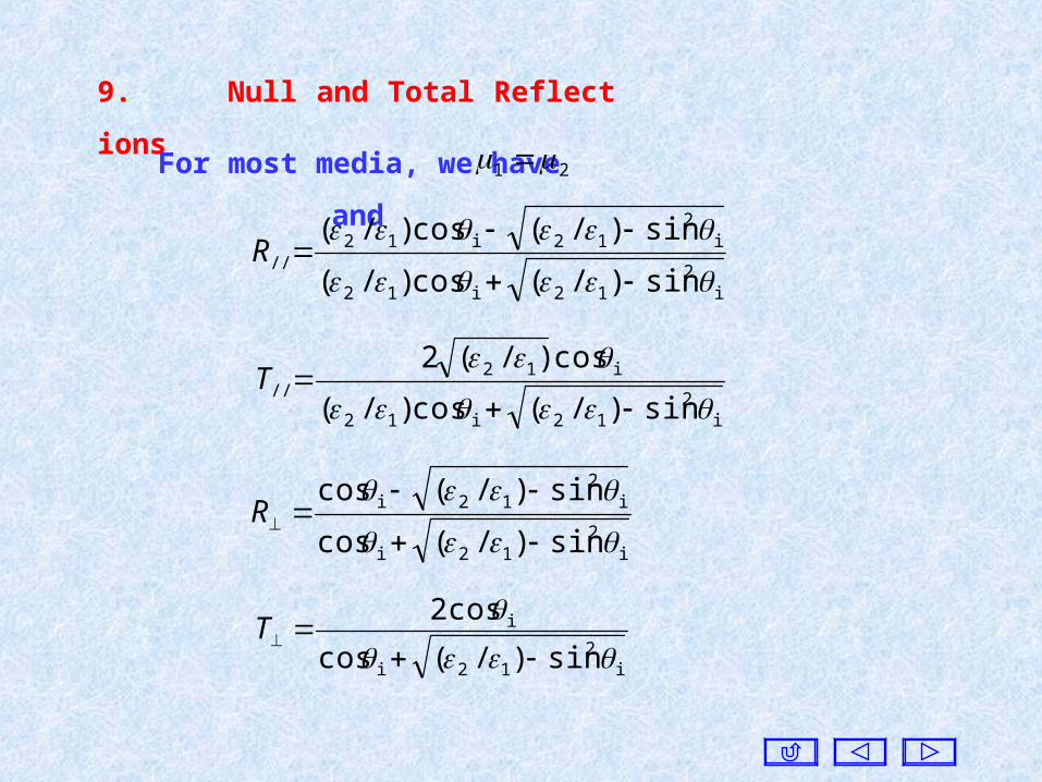
9. Null and Total Reflections
For most media, we have and21
sin)/(cos)/(
sin)/(cos)/(
i2
12i12
i2
12i12//
R
i2
12i12
i12//
sin)/(cos)/(
cos)/(2
T
sin)/(cos
sin)/(cos
i2
12i
i2
12i
R
i2
12i
i
sin)/(cos
cos2
T

i2
1
2i
1
2 sincos
i
sin1
2
Hence, if the angle of incidence satisfied the following condition:i
Due to sin)/(cos)/(
sin)/(cos)/(
i2
12i12
i2
12i12//
R
then , and it means that all of the energy of the incident wave
will enter medium ②, while the reflected wave vanishes. This
phenomenon is called null reflection or total transmission.
0// R
The angle of incidence at which null reflection arises is called
the Brewster angle denoted as B , and we find
21
2B arcsin
i
1
2 sin

We know sin)/(cos
sin)/(cos
i2
12i
i2
12i
R
The reflection coefficient only if . Hence, the perpen-
dicularly polarized wave cannot have null reflection.
21 0R
A plane wave with an arbitrary polarization can be resolved into
a parallel polarized wave and a perpendicular polarized wave.
When a beam of unpolarized light is incident on the boundary
at Brewster angle, the reflected wave becomes a perpendicular pola
rized wave since the parallel polarized portion will not be reflected.
In optical engineering, a polarized light can be obtained this way.

sin)/(cos)/(
sin)/(cos)/(
i2
12i12
i2
12i12//
R
sin)/(cos
sin)/(cos
i2
12i
i2
12i
R
If , then , and this phenomenon is calle
d total reflection. 1
2i
2sin 1// RR
From Snell’s law , we can see that if the above equation
is satisfied, then the angle of refraction will be .1
2
t
i
sin
sin
2
π
When the angle of incident is greater than the angle at
which total reflection happens, total reflection still exists.

The angle at which total reflection just happens is called the
critical angle, and it is denoted as c , and
1
2c arcsin
Since the function , total reflection will happen only if
. Namely, that happens only if a plane wave is incident on a
medium with a lower permittivity than that of the current medium.
1sin c
21
During total reflection the
refracted wave is
)cossin(jt0
t tt2e zxkEE x
z
c
1sin)/(sin/jt0
t i2
212i212 ee zkxkEE
We have
The greater the ratio or the angle of incidence is, the faster
the amplitude will be decreased in the positive z-direction.2
1
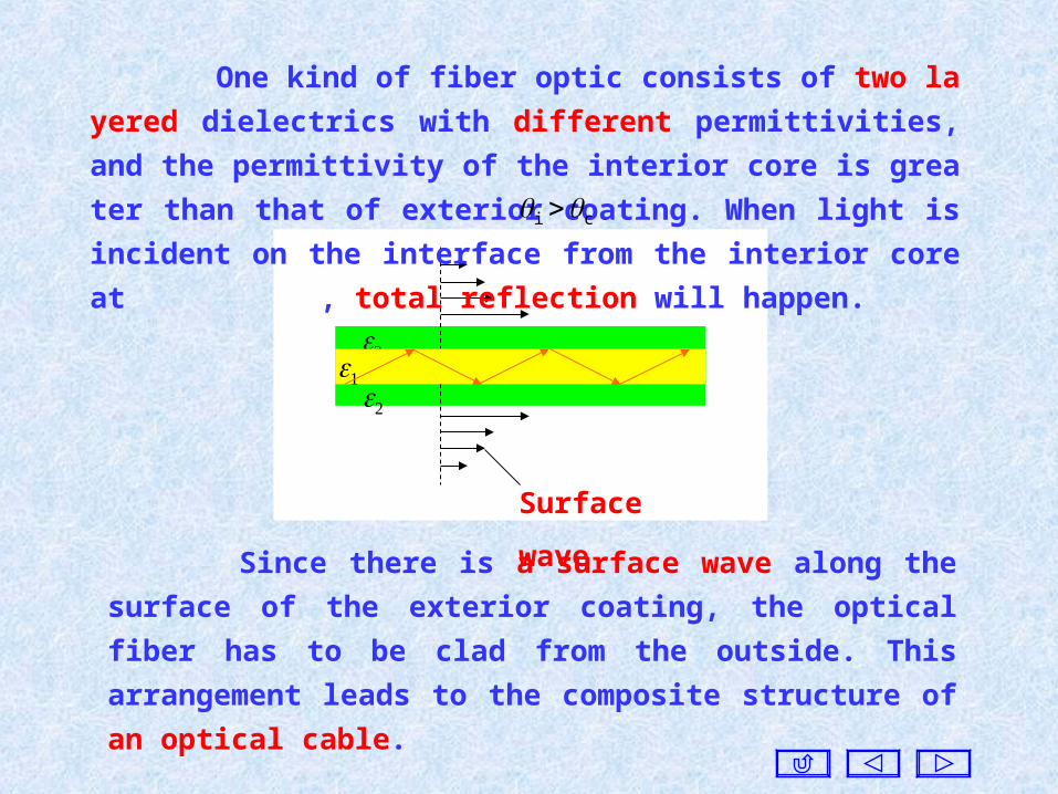
Surface wave
Since there is a surface wave along the surface of the exterior
coating, the optical fiber has to be clad from the outside. This
arrangement leads to the composite structure of an optical cable.
One kind of fiber optic consists of two layered dielectrics with dif
ferent permittivities, and the permittivity of the interior core is great
er than that of exterior coating. When light is incident on the interfac
e from the interior core at , total reflection will happen. ci

All of the results obtained above hold under the premise of . 21
If and , only the perpendicular polarized wave has
null reflection. 21 21
If and , both polarized waves can have null reflecti
on. 21 21
Example. Suppose the parameters of the medium in the region
are , and in . If the electric f
ield intensity of the incident wave is 0z ,41r 1r1 0 z1 ,9 r2r2
)3(6je)3( zyzyx
eeeE
Find: (a) The frequency.
(b) The angles of reflection and refraction.
(c) The reflected and the refracted waves.

y
i r
t
1 1
2 2
z
x
iE
i//E
r//E
t//E
rE
tE
Solution: The incident wave can
be resolved into a perpendicular
polarized wave and a parallel
polarized wave, i.e.ii
//i
EEE
)3(6ji//
)3(6ji
e)3(
ezy
zy
zyx
eeE
eEWhere
)3(6)cossin( ii1 zyzyk Due to
rii 60 2
3sin
121 k MHz287π2 11
kfWe find

From we obtain2
3
sin
sin
1
2
t
i k
k
18 ,3.353
1sin 2tt k
580.0sin)/(cos
cos2
i2
12i
i
T
0425.0sin)/(cos)/(
sin)/(cos)/(
i2
12i12
i2
12i12//
R
638.0sin)/(cos)/(
cos)/(2
i2
12i12
i12//
T
420.0sin)/(cos
sin)/(cos
i2
12i
i2
12i
RThen

)3(6jr||
)3(6jr
e)3(0425.0
e420.0zy
zy
zyx
eeE
eE
The electric field intensity of the reflected wave is , herer||
rr EEE
3
2
318j
t||
3
2
318j
t
e3
4
3
8638.0
e580.0
zy
zy
zy
x
eeE
eE
The electric field intensity of the refracted wave is , here t||
tt EEE
Note that the change of the propagating directions of the reflected
and the refracted waves in the calculations.

10. Oblique Incidence at Conducting Boundary
Suppose medium ① is a perfect dielectric, while medium ② is a
conducting medium, i.e. 0 ,0 21
For medium ② we use the equivalent permittivity. Namely, let
e22
2 j
Then the intrinsic impedance of medium ② is
2
2
2c2
jZ
Since Zc2 is a complex number, both the reflection and the refra
ction coefficients are complex numbers, the null reflection and the tot
al reflection conditions cannot arise.

The equiamplitude surface and the wave front are not in the sam
e plane. Hence, it is a non-uniform plane wave.
2
1i
2
t
i sinsin
sin
k
The modified Snell’s
refraction law is
0sinsin i1
t
kIf , we have22
0t i.e.
when a plane wave is incident on the sea surface from the air,
if the seawater can be considered to be the good conductor for the
given frequency, the refracted wave propagates almost vertically
downward regardless of the angle of incidence.
For communication with submarines, the main lobe of the
receiving antenna pattern must be directed upward.
i r
1 1
2 2 2
z
xEquiamplitude surface
Wave front
Wave frontEquiamplitude surface
t

Suppose medium ① is a perfect dielectric, and medium
② is a perfect conductor, so that
11. Oblique Incidence at Perfect Conducting Boundary
21 ,0
1 ,1|| RR
And the reflective coefficients are
Then the intrinsic impedance of medium ② is 0j 2
2
22c
Z
It means that when a plane wave is incident on the surface of a
perfect conductor, total reflection always happens regardless of the
angle of incidence and the polarization.
Since the reflection coefficient is related to the polarization of
the incident wave. Consequently the distribution of the field in
the above half-space depends on the polarization.

)cossin(ji
i0
ii1ecos zxkx EE )cossin(j
ir0
ii1ecos zxkE
For the parallel polarized wave, the x-component of the resultant
electric field is
Consider , , we
have
1|| R i0
r0 EE
i1 sinji1i
i0 e)cossin(cosj2 xk
x zkEE
In the same way, the z-component of the resultant electric field
and the resultant magnetic field respectively are
i1 sinji1i
i0 e)coscos(sin2 xk
z zkEE
i1 sinji1
1
i0 e)coscos(2 xk
y zkZ
EH
The phase of the resultant wave is changed with the variable x,
while the amplitude is related to the variable z. Hence, the resultant
wave is a non-uniform plane wave traveling in the positive x-direction.
O
1 = 0
2 =
x
z
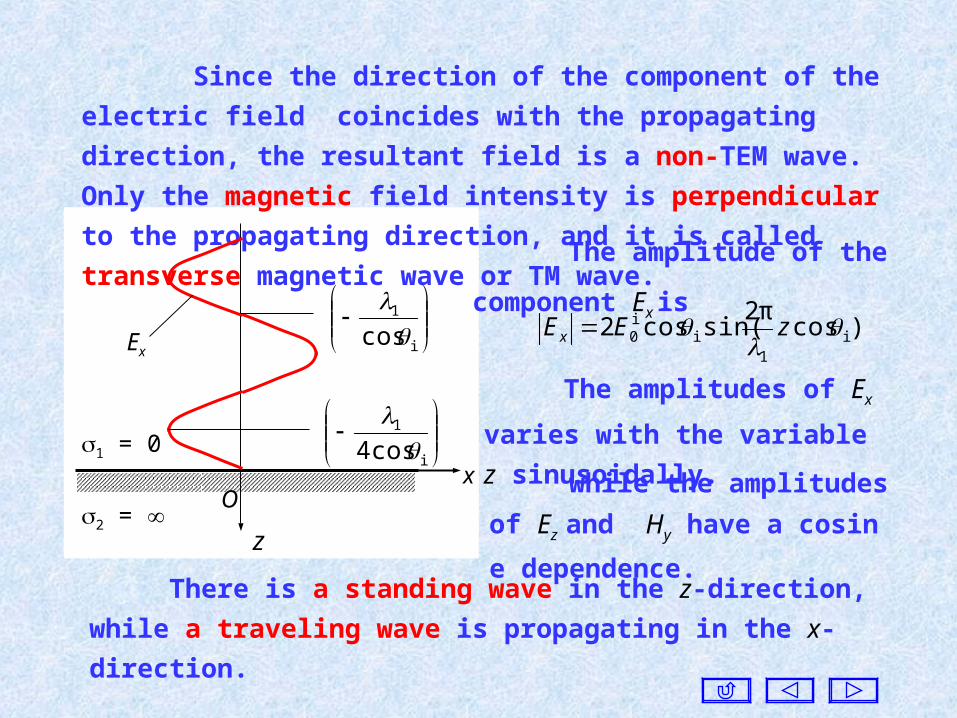
Since the direction of the component of the electric field coincides
with the propagating direction, the resultant field is a non-TEM wave.
Only the magnetic field intensity is perpendicular to the propagating
direction, and it is called transverse magnetic wave or TM wave.
Ex
i
1
cos
i
1
cos4
The amplitude of the component
Ex is
The amplitudes of Ex varies with
the variable z sinusoidally.
)cosπ2
sin(cos2 i1
ii0
zEEx
while the amplitudes of Ez and
Hy have a cosine dependence.
There is a standing wave in the z-direction, while a traveling wave is
propagating in the x-direction.
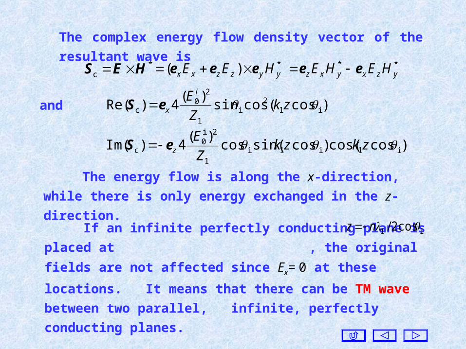
The complex energy flow density vector of the resultant wave is
*c HES *)( yyzzxx HEE eee **
yzxyxz HEHE ee
)cos(cossin)(
4)Re( i12
i1
20
c zkZ
E i
xeS
)coscos()cossin(cos)(
4)Im( i1i1i1
2i0
c zkzkZ
EzeS
and
The energy flow is along the x-direction, while there is only energy
exchanged in the z-direction.
If an infinite perfectly conducting plane is placed at ,
the original fields are not affected since Ex= 0 at these locations. It
means that there can be TM wave between two parallel, infinite,
perfectly conducting planes.
i1 cos2/ nz

Ex
O
1 = 0
2 =
x
z
Infinite, perfectly
conducting plane
TM Wave
E
HS x

For the perpendicular polarized wave, we have
e)cossin(2j i1 sinji1
i0
xky zkEE
i1 sinji1i
1
i0 e)coscos(cos2 xk
x zkZ
EH
i1 sinji1i
1
i0 e)cossin(sin2j xk
z zkZ
EH
It is still a non-uniform plane wave traveling in the x-direction.
However, only the electric field is perpendicular to the propagating
direction, and it is called transverse electric wave or TE wave.
The amplitudes of Ey and Hz vary with the variable z sinusoidally
, while the amplitude of Hx has a cosine dependence. If an infinite perfect conducting plane is placed at ,
the original fields are not affected since at these locations. It
means that there can be TE waves between two parallel, infinite,
perfectly conducting planes.
i1 cos2/ nz 0yE

We will see that a rectangular or circular waveguide can transmit
TE and TM waves only, but TEM wave.
Ey
0
1 = 0
2 =
y
z
TE wave
E
H
S x
If two more perfectly conducting planes are placed perpendi-c
ularly to the y-axis, it does affect the original fields as well since is
perpendicular to these planes. In this way, a TE wave can exist in a
rectangular metal tube consisting of the four perfectly conducting p
lanes.
yE

Example. A perpendicular polarized plane wave is incident on an
infinite perfectly conducting plane with an angle of incidence i from
the air. If the amplitude of the electric field of the incident wave is ,
find the surface electric current density on the conducting surface and
the average energy flow density vector in air.
i0E
i r 0 0
E i E r
H i H r
z
x
O
0n
zxzS HeHeJ
i1 sinji
0
i0 ecos
2 xkyS Z
E eJand
Using , we find the x -component of the magnetic field isHEk
i1 sinji1i
1
i0 e)coscos(cos2 xk
xx zkZ
E eH
Solution: Let the boundary be at
the plane , Then the surface
electric current density JS is
0z

The average of the energy flow density vector is
)Re()Re( *cav HESS )](Re[ **
zxy HHE
We know that
e)cossin(2j i1 sinji1
i0
xkyy zkE eE
i1 sinji1i
1
i0 e)coscos(cos2 xk
xx zkZ
E eH
i1 sinji1i
1
i0 e)cossin(sin2j xk
zz zkZ
E eH
)cos(sinsin)(
4 i12
i0
2i0
av zkZ
ExeS Find

12. Plane Waves in Plasma The plasma is a kind of ionized gas, consisting of electrons,
positive ions and neutral molecules. The ionosphere in the range
60~2000km above the earth is a plasma.
Under the influence of a steady magnetic field, a plasma will
exhibit anisotropic electric behavior, with the permittivity having
up to 9 elements. Hence, in the terrestrial magnetic field the iono
sphere appears in electric anisotropy.
The terrestrial magnetic flux density is about 0.03~0.07mT.
33
2221
1211
00
0,,
0,,
The permittivity is
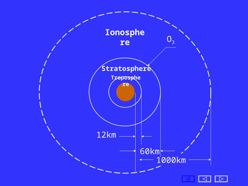
Ionosphere
1000km
Troposphere
12km
Stratosphere
60km
O3
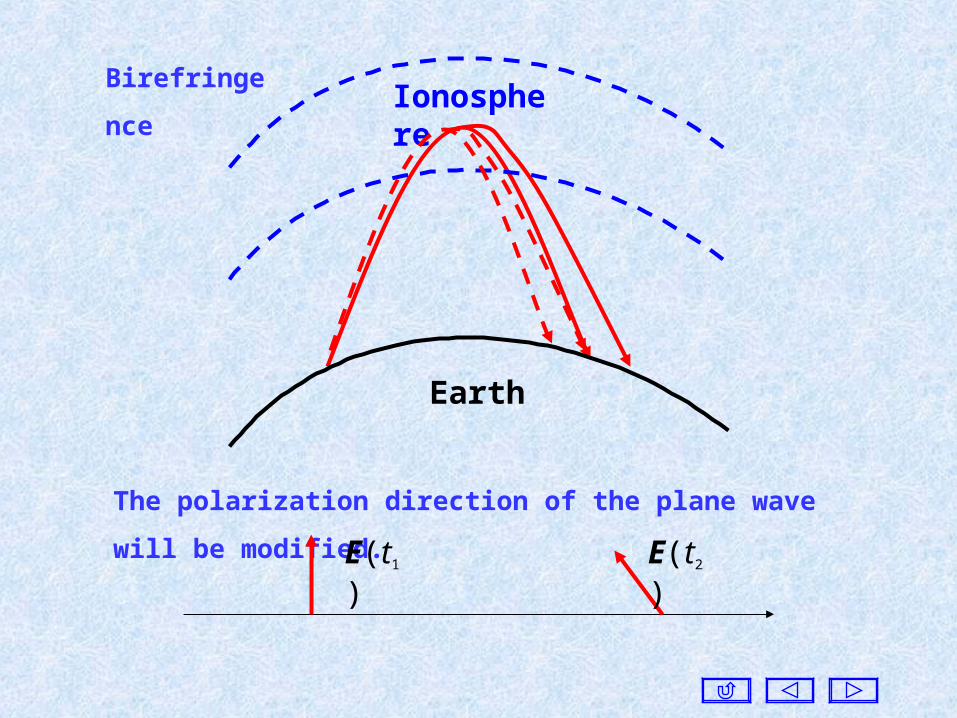
The polarization direction of the plane wave will be modified.
Earth
Ionosphere
E(t1) E(t2)
Birefringence

13. Plane Waves in Ferrite
Ferrite is a kind of magnetic material. Its permeability is very
large and the relative permittivity r = 2~35, but the conductivity is
about 10-4~1 (S/m).
33
2221
1211
00
0
0
When a plane wave is propagating in ferrite, the birefringence
and the modification of the polarization direction of plane wave
will also happen. The change in the polarization direction is used
in microwave devices.
Under the influence of a steady magnetic field, a ferrite will
display anisotropic magnetic behavior.