Embed Size (px)
Citation preview

Chapter
1Introduction to Computer Networking
THE FOLLOWING CWTS EXAM OBJECTIVE IS COVERED IN THIS CHAPTER:
1.4 Explain the role of Wi-Fi as a network access
technology
The OSI reference model
c01.indd 1c01.indd 1 8/10/2012 12:34:45 PM8/10/2012 12:34:45 PM
COPYRIG
HTED M
ATERIAL

It is important to have an understanding of basic computer networking concepts before you begin exploring the world of wireless networking technology and its terminology. This
chapter looks at various topics surrounding computer networking including network types (LAN and WAN), topologies, the OSI model, and device addressing. The chapter is intended to provide an overview of basic networking concepts as an introduction for those who need to gain a basic understanding or for those who want a review of the concepts.
You will look at the various types of wireless networks—including wireless personal area networks (WPANs), wireless local area networks (WLANs), wireless metro-politan area networks (WMANs), and wireless wide area networks (WWANs)—in Chapter 2, “Introduction to Wireless Local Area Networking.”
Network TypesPersonal computer networking technology has evolved at a tremendous pace over the past couple of decades, and many people across the world now have some type of exposure to the technology. Initially, personal computers were connected, or “networked” together, to share fi les and printers. This type of network was usually confi ned to a few rooms or within a single building. As the need for this technology continued to grow, so did the types of networks. Networking started with the local area network (LAN) and grew on to bigger and better types, including wide area networks (WANs) and metropolitan area networks (MANs). The following are some of the common networking types in use today:
Local area networks (LANs)
Wide area networks (WANs)
Metropolitan area networks (MANs)
Campus area networks (CANs)
Personal area networks (PANs)
The Local Area Network
A local area network (LAN) can be defi ned as a group of computers connected by a physi-cal medium in a specifi c arrangement called a topology. The topology used depends on the
c01.indd 2c01.indd 2 8/10/2012 12:34:48 PM8/10/2012 12:34:48 PM

Network Types 3
location where the network is installed. Some common topologies such as bus, ring, and star are discussed later in this chapter. Local area networks are contained in the same phys-ical area and usually are bounded by the perimeter of a building. However, in some cases a LAN may span a group of buildings in close proximity that are on the same subnet.
Common uses of early LANs were mostly for fi le and print services. This allowed users to store data securely and provided a centralized location of data for accessibility when the user was physically away from the LAN. This central storage of data also provided the abil-ity for a network administrator to back up and archive all the saved data for disaster recov-ery purposes. As for print services, it was not cost effective to have a printer at every desk, so LANs allowed the use of shared printers for any user on the local area network. Figure 1.1 illustrates a local area network that includes both wired and wireless devices.
F I GU R E 1.1 A local area network (LAN)
Network Printer
Wireless Access Point
Wireless Client Device
Computer Workstations
File Server
The Wide Area Network
As computer networking continued to evolve, many businesses and organizations that used this type of technology needed to expand the LAN beyond the physical limits of a single area or building. The local area networks began to expand into the wide area network (WAN). As illustrated in Figure 1.2, a WAN mostly consists of point-to-point or point-to-multipoint connections between two or more LANs and may span a relatively large geo-graphical area. The WAN has allowed users and organizations to share data fi les and other resources with a much larger audience.
WANs can use leased lines from telecommunication providers (commonly known as “telcos”), fi ber connections, and even wireless connections. The use of wireless for bridging local area networks is growing at a fast pace, because it can often be a cost-effective solu-tion for connecting LANs together.
c01.indd 3c01.indd 3 8/10/2012 12:34:48 PM8/10/2012 12:34:48 PM

4 Chapter 1 Introduction to Computer Networking
F I GU R E 1. 2 Wide area network (WAN) connecting three LANs
LAN 1
Point-to-Point or Point-to-Multipoint
Links for Connections
LAN 3LAN 2
Point-to-Point Connections
Connecting at least two LANs together is known as a point-to-point connection or link (see Figure 1.3). The connection can be made using either wired or wireless network infra-structure devices and can include bridges, wireless access points, and routers. Wireless LAN (WLAN) point-to-point links can sometimes extend very long distances depending on terrain and other local conditions. These links can serve both wired and wireless users on the connected local area networks.
Wired point-to-point links consist of fi ber-optic connections or leased lines from local telecommunication providers. Wireless point-to-point links typically call for semidirec-tional or highly directional antennas. With some regulatory domains such as the Federal Communications Commission (FCC), when an omnidirectional antenna is used in this confi guration it is considered a special case, called a point-to-multipoint link. Wireless point-to-point links include directional antennas and encryption to protect the wireless data as it propagates through the air.
Point-to-Multipoint Connections
A network infrastructure connecting more than two LANs together is known as a point-to-multipoint connection or link (see Figure 1.4). When used with wireless, this confi guration usually consists of one omnidirectional antenna and multiple semidirectional or highly direc-tional antennas. Point-to-multipoint links are often used in campus-style deployments, where connections to multiple buildings or locations may be required. Point-to-multipoint WANs are often called “clouds.” Like point-to-point connections, wired point-to-multipoint connections can use either direct wired connections such as fi ber-optic cables or leased line connectivity available from telecommunication providers.
c01.indd 4c01.indd 4 8/10/2012 12:34:48 PM8/10/2012 12:34:48 PM
Network Types 5
F I GU R E 1. 3 Point-to-point connections using either wired or wireless
LAN 2LAN 1
Wired Point-to-Point
Wireless Point-to-Point
F I GU R E 1. 4 Point-to-multipoint connections using either wired or wireless
LAN 2LAN 1 LAN 3
Wired Point-to-Multipoint
Wireless Point-to-Multipoint
The Metropolitan Area Network
The metropolitan area network (MAN) consists of networks that can span from several blocks of buildings to entire cities and interconnect devices for access to computer resources in a region or area larger than that covered by local area networks (LANs) but yet smaller
c01.indd 5c01.indd 5 8/10/2012 12:34:49 PM8/10/2012 12:34:49 PM

6 Chapter 1 Introduction to Computer Networking
than the areas covered by wide area networks (WANs). The MAN is growing in popularity as the need for access in this type of environment also increases. MANs also include fast connectivity between local networks and may include fi ber optics or other wired connectiv-ity that is capable of longer distances and higher capacity than those in a LAN.
MANs also allow for connections to outside larger networks such as the Internet. They may include services such as cable TV, streaming video, and telephone. Devices and con-nectivity used with metropolitan area networks may be owned by a town, county, or other locality and may also include the property of individual companies. Wireless MANs are also becoming a common way to connect the same type of areas. Wireless MANs will be discussed further in Chapter 2.
Campus Area Networks
A campus area network (CAN) includes a set of interconnected LANs, is basically a smaller version of a wide area network (WAN) within an offi ce or school campus, and is usually within a limited geographical area. Each building within the campus would have a separate LAN, and the LANs are often connected using fi ber-optic cable, which provides a greater distance than copper wiring using IEEE 802.3 Ethernet technology. Wireless connections between the buildings used with CANs are now a common way to connect the individual LANs. These wireless connections or wireless bridges provide a quick, cost-effective way to connect buildings together in a university campus.
In a university campus environment, a CAN may link many buildings, including all of the various schools—School of Business, School of Law, School of Engineering, and so on—as well as the university library, administration buildings, and even residence halls. Wireless LAN deployments are becoming commonplace in university residence halls. With the number of mobile wireless devices increasing at a very fast pace in places like university campus residence halls, the number of wireless access points and the capacity of each need to be considered.
As in the university campus environment, a corporate offi ce CAN may connect together all the various building LANs that are part of the organization. This type of network will have the same characteristics of a WAN but confi ned to the internal resources of the cor-poration or organization. Many organizations are deploying wireless networks within the corporate CAN as a way to connect various parts of the business together. Like the uni-versity CAN, in the corporate world wireless can be a quick, cost-effective way to provide connectivity between buildings and departments. All of the physical connection mediums and devices are the property of the offi ce or school campus, and responsibility for the maintenance of the equipment lies with the offi ce or campus as well.
Personal Area Networks
Personal area networks (PANs) are networks that connect devices within the immediate area of individual people. PANs may consist of either wired or wireless connections or both. On the wired side, this includes universal serial bus (USB) devices such as printers,
c01.indd 6c01.indd 6 8/10/2012 12:34:49 PM8/10/2012 12:34:49 PM

Network Topologies 7
keyboards, and computer mice that may be connected with a USB hub. With wireless tech-nology, PANs are short-range computer networks and in many cases use Bluetooth wireless technology. Wireless Bluetooth technology is specifi ed by the IEEE 802.15 standard and is not IEEE 802.11 wireless local area technology. Bluetooth will be discussed in more detail in Chapter 5, “Physical Layer Access Methods and Spread Spectrum Technology.”
Like wired PANs, wireless PANs are commonly used in connecting an individual’s wireless personal communication accessories such as phones, headsets, computer mice, keyboards tablets, and printers and are centered on the individual personal workspace without the need for physical cabling. Figure 1.5 illustrates a typical wireless PAN confi guration.
F I GU R E 1.5 Bluetooth network connecting several personal devices together
Headset
Mobile phone
Printer
Computer
Tablet
Network TopologiesA computer physical network topology is the actual layout or physical design and intercon-nection of a computer network. A topology includes the cabling and devices that are part of the network. In this section you will look at several network topologies:
Bus
Ring
Star
Mesh
c01.indd 7c01.indd 7 8/10/2012 12:34:49 PM8/10/2012 12:34:49 PM
8 Chapter 1 Introduction to Computer Networking
Bus
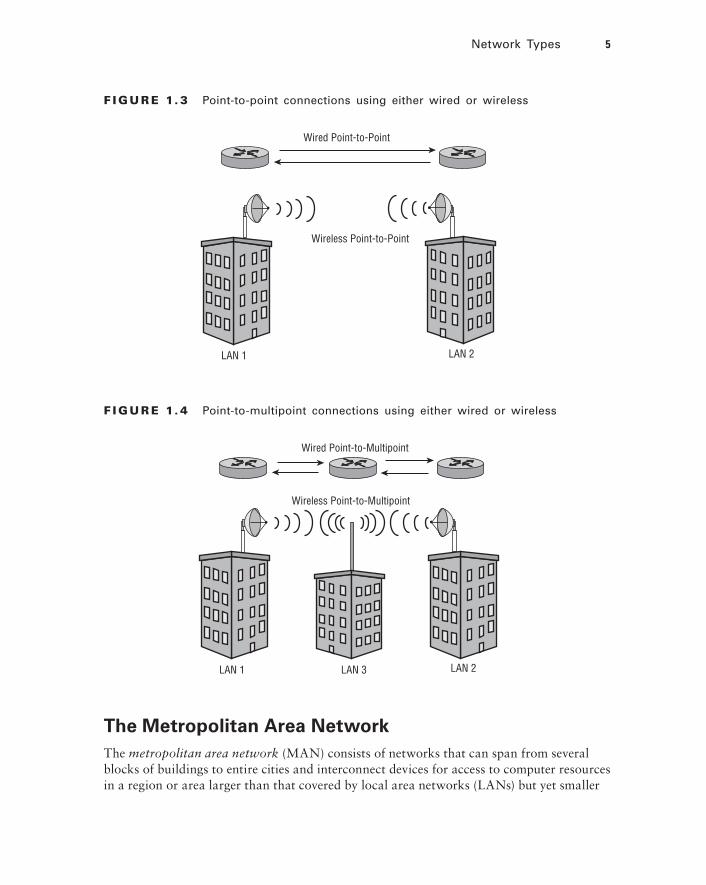
A bus topology consists of multiple devices connected along a single shared medium with two defi ned endpoints. It is sometimes referred to as a high-speed linear bus and is a single broadcast domain in which all devices on the bus network receive all messages. Both endpoints of a bus topology have a 50 ohm termination device, usually a Bayonet Neill–Concelman (BNC) connector with a 50 ohm resistor. The bus topology is now considered a legacy design and was commonly used with early local area networking.
One disadvantage to the bus topology is that if any point along the cable is damaged or broken, the entire LAN goes down. Troubleshooting a bus network is performed by some-thing known as the half-split method. A network engineer “breaks” or separates the link at about the halfway point and measures the resistance on both ends. If the segment measures 50 ohms, there is a good chance that side of the LAN segment is functioning correctly. If the resistance measurement is not 50 ohms, it signals a problem with that part of the LAN segment. The engineer continues with this method until the exact location of the problem is identifi ed. Figure 1.6 illustrates an example of the bus topology.
F I GU R E 1.6 Example of the bus topology
Network Printer ComputerComputer
Computer
50 Ohm Terminator
50 Ohm Terminator
File Server
Ring
The ring topology is rarely used with LANs today, but it is still widely used by Internet service providers (ISPs) for high-speed, resilient backhaul connections over fi ber-optic links. In the ring topology, each device connects to two other devices, forming a ring pat-tern. Ring topologies in LANs may use a token-passing access method, in which data travels around the ring in one direction. Only one device at a time will have the opportu-nity to transmit data. Because this access method does not use collision detection, it will commonly outperform the bus topology, achieving higher data rates than are possible using a collision detection access method. Each computer on the ring topology can act as a repeater, a capacity that allows for a much stronger signal. Figure 1.7 shows an example of the ring topology.
c01.indd 8c01.indd 8 8/10/2012 12:34:50 PM8/10/2012 12:34:50 PM

Network Topologies 9
Troubleshooting the Bus Topology
I remember many years ago I was called to troubleshoot a problem on a small local area network using a bus topology. The network consisted of a network fi le server, about 20 client stations, and a few network printers. The users complained of intermittent problems with the network. After spending some time looking over the network, I decided to test the bus using the half-split method and checked to verify that the cable was reporting the correct resistance using a volt-ohm-milliamp (VoM) meter. Sure enough, one side of the network cable reported the correct resis-tance reading, but the other side was giving intermittent results.
After spending some time repeating the troubleshooting method, I was able to determine the problem. It turns out that someone had run the coax (bus) cable underneath a heavy plastic offi ce chair mat and one of the little pegs used to pro-tect the fl ooring was causing the intermittent connection as it struck the cable when the user moved their chair around the mat. I quickly replaced and rerouted the sec-tion of cable in question. It is a good thing I was there during the normal business operating hours when the person was moving around in the chair or I might have never found the problem. Ah, the joys of troubleshooting a bus topology.
F I GU R E 1.7 An example of the ring topology
Computer
Computer
Computer
Computer
Computer
File Server
c01.indd 9c01.indd 9 8/10/2012 12:34:50 PM8/10/2012 12:34:50 PM

10 Chapter 1 Introduction to Computer Networking
Star
The star topology, as shown in Figure 1.8, is the most commonly used method of connect-ing devices together on a LAN today. It consists of multiple devices connected by a central connection device. Common central connection devices include hubs, switches, and wire-less access points, although hubs are rarely used today. The hub provides a single broadcast domain similar to a bus topology. However, the switch and wireless access point both have intelligence—the ability to decide which port specifi c network traffi c can be sent to. A big advantage over the bus and ring topologies is that if a connection is broken or damaged the entire network is not down; only a single device in the star topology is affected. However, the central connection device such as a switch or wireless access point can be considered a potential central point of failure.
F I GU R E 1. 8 A common star topology using either wired or wireless devices
Network Printer
Computer
Computer
Computer
File Server
Wireless Access Point
Wireless Computers
Wireless Computers
Mesh
Each device in a mesh topology (Figure 1.9) has one or more connections to other devices that are part of the mesh. This approach provides both network resilience in case of link
c01.indd 10c01.indd 10 8/10/2012 12:34:50 PM8/10/2012 12:34:50 PM
The OSI Model 11
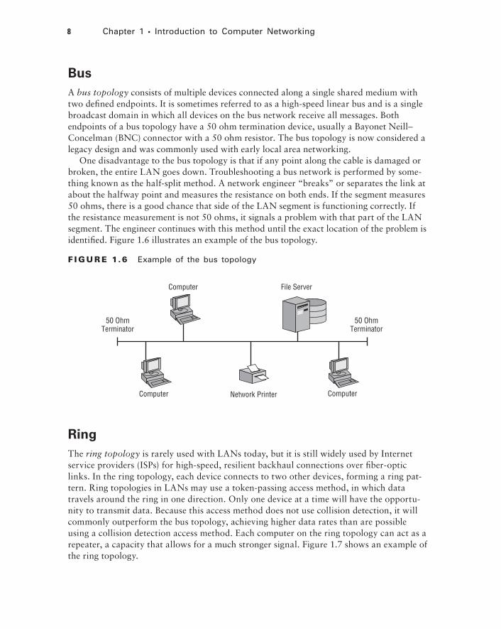
or device failure and a cost savings compared to full redundancy. Mesh technology can operate with both wired and wireless infrastructure network devices. The amendment to the IEEE 802.11 standard for mesh networking is 802.11s. This amendment was ratifi ed in 2011 and is now part of the IEEE 802.11-2012 standard.
Manufacturers currently are using proprietary Layer 2 routing protocols, forming a self-healing wireless infrastructure (mesh) in which edge devices can communicate. Manufacturers of enterprise wireless networking infrastructure devices provide support for mesh access points (APs) such that the mesh APs connect back to APs that are directly wired into the network backbone infrastructure. This is a form of wireless distribution sys-tem (WDS) deployment. The APs or wireless controllers in this case are used to confi gure both the wired and mesh APs.
F I GU R E 1. 9 Mesh networks can be either wired or wireless devices.
Mesh Routers
Wireless Mesh Routers
The OSI ModelBefore we continue with wireless LAN technology, you should have some background on computer networking theory. The basics of a computer networking discussion start with the OSI model. The Open Systems Interconnection (OSI) model has been around for sev-eral decades. It describes the basic concept of communications in the computer network environment.
There are seven layers to the OSI model. Each layer is made up of many protocols and serves a specifi c function. You will take a quick look at all seven layers of the OSI but only layers that pertain to wireless networking will be discussed in depth in this book. Figure 1.10 illustrates the seven layers of the OSI model.
c01.indd 11c01.indd 11 8/10/2012 12:34:51 PM8/10/2012 12:34:51 PM

12 Chapter 1 Introduction to Computer Networking
F I GU R E 1.10 The OSI model
Application Layer 7
Layer 6
Layer 5
Layer 4
Layer 3
Layer 2
Layer 1
Presentation
Session
Transport
Network
Data Link
Physical
Wireless networking functions at the two lowest layers of the OSI model, Layer 1 (Physical) and Layer 2 (Data Link). However, to some degree Layer 3 (Network) plays a role as well, generally for the TCP/IP protocol capabilities. Here’s how each layer is used:
Layer 1 (PHY, the Physical layer) consists of bit-level data streams and computer network hardware connecting the devices together. This hardware includes network interface cards, cables, switches, wireless access points, and bridges. In the case of wireless networking, radio frequency (RF) uses air as the medium for wireless com-munications. The Physical layer consists of two sublayers: the Physical Layer Conver-gence Protocol (PLCP) and Physical Medium Dependent (PMD). The PLCP, the higher of the two layers, is the interface between the PMD and Media Access Control (MAC) sublayer. The PMD is the lower sublayer at the bottom of the protocol stack and is responsible for transmitting the data onto the wireless medium.
Layer 2 (Data Link layer) is responsible for organizing the bit-level data for communica-tion between devices on a network and detecting and correcting Physical layer errors. The Data Link layer consists of two sublayers: the Logical Link Control (LLC) sublayer and Media Access Control (MAC) sublayer. The bit-level communication is accom-plished through Media Access Control (MAC) addressing. A MAC address is a unique identifier of each device on the computer network and is known as the physical address.
Layer 3 (Network layer) is where the Internet Protocol (IP) protocol resides and is responsible for addressing and routing data. An IP address is defined as a numerical identifier or logical address assigned to a network device. The IP address can be static, manually assigned by a user, or it can be dynamically assigned from a server.
Layer 4 (Transport layer) Transmission Control Protocol (TCP) is a connection-oriented protocol and is used for communications requiring reliability and is analogous to a circuit-switched phone call. User Datagram Protocol (UDP) is a connectionless protocol and is used for simple communications requiring efficiency. UDP is analogous to sending a postcard through a mail service. You would not know if the postcard was received. UDP and TCP port numbers are assigned to applications for flow control and error recovery.
c01.indd 12c01.indd 12 8/10/2012 12:34:51 PM8/10/2012 12:34:51 PM

The OSI Model 13
Layer 5 (Session layer) opens, closes, and manages sessions between end-user applica-tion processes.
Layer 6 (Presentation layer) provides delivery and formatting of information for pro-cessing and display.
Layer 7 (Application layer) “Application” is another term for a “program” that runs on a computer or other networking device. Examples of Application layer protocols are File Transfer Protocol (FTP), Hypertext Transfer Protocol (HTTP), and Post Office Protocol v3 (POP3).
In order for computers and other network devices to communicate with one another using the OSI model, a communication infrastructure of some type is necessary. In a wired network, such an infrastructure consists of cables, repeaters, bridges, and Layer 2 switches. In a wireless network, these devices are access points, bridges, repeaters, radio frequency, and the open air. All will be discussed in more detail in Chapter 3, “Wireless LAN Infrastructure Devices.”
OSI Model Memorization Tip
One common method you can use to remember the seven layers of the OSI model from top to bottom is to memorize the following sentence: “All people seem to need data processing.” Take the fi rst letter from each word and that will give you an easy way to remember the fi rst letter that pertains to each layer of the OSI model.
All (Application)
People (Presentation)
Seem (Session)
To (Transport)
Need (Network)
Data (Data Link)
Processing (Physical)
Peer Communication
Peer layers communicate with other peer layers, and the layers underneath are their support systems. Peer layer communication is the “horizontal” link between devices on the network. Figure 1.11 shows only three examples of peer communication. Keep in mind, however, that this principle applies to all seven layers of the OSI model. This allows for the layers to com-municate with the corresponding layer to which a device is sending or receiving information.
c01.indd 13c01.indd 13 8/10/2012 12:34:51 PM8/10/2012 12:34:51 PM

14 Chapter 1 Introduction to Computer Networking
F I GU R E 1.11 Peer communication between three of the seven layers
APPLICATIONPRESENTATIONSESSIONTRANSPORTNETWORKDATA LINKPHYSICAL
APPLICATIONDirect Connection
Direct Connection
Direct Connection
Encapsulation
PRESENTATIONSESSIONTRANSPORTNETWORKDATA LINKPHYSICAL
Encapsulation
The purpose of encapsulation is to allow Application layer data communication between two stations on a network using the lower layers as a support system. As data moves down the OSI model from the source to the destination, it is encapsulated. As data moves back up the OSI model from the source to the destination, it is decapsulated. Each layer adds a header and/or trailer when information is being transmitted and removes them when infor-mation is being received. Encapsulation is the method in which lower layers support upper layers. Figure 1.12 illustrates the process.
F I GU R E 1.12 Information is added at each layer of the OSI model as data moves between devices.
Application
Presentation
Session
Transport
Network
Data Link
Physical Layer 1 Header
Layer 2 Header
Layer 3 Header
Layer 4 Header Data
Layer 2 Header
Layer 3 Header
Layer 4 Header Data
Layer 3 Header
Layer 4 Header Data
Layer 4 Header Data
Encapsulation
Data
c01.indd 14c01.indd 14 8/10/2012 12:34:51 PM8/10/2012 12:34:51 PM

Device Addressing 15
Device AddressingEvery device on a network requires unique identifi cation. This can be accomplished in a couple of ways:
Physical addresses
Logical addresses
The physical address of a network adapter is also known as the media access control (MAC) address. As shown in Figure 1.13, every device on a network (like every street address in a city) must have a unique address.
The logical address is also known as the Internet Protocol (IP) address. Every device on a Layer 3 network (like every city’s zip code) must have a unique IP address.
F I GU R E 1.13 The MAC address is analogous to the address of buildings on a street.
10 Main Street Unique Address = 10
20 Main Street Unique Address = 20
120 2nd Street Unique Address = 120
131 2nd Street Unique Address = 131
Main Street = LAN 2
123 1st Street Unique Address = 123
1st S
treet
= L
AN 1
2nd
Stre
et =
LAN
3
The streets shown in Figure 1.13—1st, Main, and 2nd—represent Local Area Networks. The unique street addresses—10, 20, and so on—represent a unique address of each struc-ture on a street as a MAC address would a device on a LAN.
c01.indd 15c01.indd 15 8/10/2012 12:34:52 PM8/10/2012 12:34:52 PM

16 Chapter 1 Introduction to Computer Networking
Physical Addressing
The physical address of a network device is called a MAC address because the MAC sub-layer of the Data Link layer handles media access control. The MAC address is a 6-byte (12-character) hexadecimal address in the format AB:CD:EF:12:34:56. The fi rst 3 bytes (or octets) of a MAC address are called the organizationally unique identifi er (OUI). Some manufacturers produce many network devices and therefore require several OUIs. A table of all OUIs is freely available from the IEEE Standards Association website at http://standards.ieee.org/develop/regauth/oui/oui.txt. MAC addresses are globally unique; an example is shown in Figure 1.14. The fi rst 3 bytes or octets (6 characters) are issued to manufacturers by the IEEE. The last 3 bytes or octets (6 characters) are incrementally assigned to devices by the manufacturer.
F I GU R E 1.14 Example of a Layer 2 MAC address
The MAC address of a device is usually stamped or printed somewhere on the device. This allows the device to be physically identifi ed by the MAC address. By typing the simple command ipconfig /all in the command-line interface of some operating systems, you can view the physical address of the network adapter. Figure 1.15 shows an example of the information displayed by using this command-line utility in the Microsoft Windows oper-ating system.
F I GU R E 1.15 The ipconfig command-line utility displaying a physical/MAC address in Microsoft Windows XP
MAC Address Information
c01.indd 16c01.indd 16 8/10/2012 12:34:52 PM8/10/2012 12:34:52 PM

Device Addressing 17
Logical Addressing
Network devices can also be identifi ed by a logical address, known as the Internet Protocol (IP) address. The Layer 3 IP protocol works with a Layer 4 transport protocol, either User Datagram Protocol (UDP) or Transport Layer Protocol (TCP). UDP is a connectionless protocol analogous to a postcard being sent through the mail. The sender has no way of knowing if the card was received by the intended recipient. TCP is a connection-oriented protocol analogous to a telephone call and provides guaranteed delivery of data. During a telephone conversation, communication between two people will be confi rmed to be intact, with the users acknowledging the conversation. Routable logical addresses such as TCP/IP addresses became more popular with the evolution of the Internet and the Hypertext Transfer Protocol (HTTP) that is used with the World Wide Web (WWW) service. IP moves data through an internetwork such as the Internet one router (or hop) at a time. Each router makes a decision where to send the data based on the logical IP address. Figure 1.16 shows a basic network utilizing both Layer 2 and Layer 3 data traffi c.
F I GU R E 1.16 A network with Layer 3 network device logical addressing
10.0.0.1 (IP Address)255.0.0.0 (Subnet Mask)
Layer 2 Data Traffic
Network Resources
Layer 2 Data Traffic
Router Layer 3 Data/Traffic
192.168.100.1 (IP Address)255.255.255.0 (Subnet Mask)
Logical addresses (IP addresses) are 32-bit dotted decimal addresses usually written in the form www.xxx.yyy.zzz. Figure 1.17 illustrates an example of a logical Class C, 32-bit IP address. Each of the four parts is a byte, or 8 digital bits. There are two main IP address types: public addresses and private addresses. Private addresses are unique to an internal network, and public addresses are unique to the Internet. These addresses consist of two main parts: the network (subnet) and the host (device). Logical addresses also require a subnet mask and may have a gateway address depending on whether the network is routed. IP addresses fall under three classes: Class A addresses, Class B addresses, and Class C addresses.
c01.indd 17c01.indd 17 8/10/2012 12:34:52 PM8/10/2012 12:34:52 PM

18 Chapter 1 Introduction to Computer Networking
F I GU R E 1.17 Example of a Class C logical IP address
A 32-bit Class C Address Shown in Dotted Decimal Notation
Network
First Byte Second Byte Third Byte Fourth Byte
Four Bytes Each Containing Eight Digital Bits
192.168.100.1
11000000.10101000.01100100.0000001
Host
Unlike a MAC address, an IP address is logical and can be either specifi ed as a static address assigned to the device by the user or dynamically assigned by a server. However, the same command-line utility used to identify the physical address of a device can be used to identify the logical address of a device.
Typing ipconfig at a command prompt displays the logical address, including the IP address, subnet mask and default gateway (router) of the device. The ipconfig /all com-mand illustrated earlier in the chapter will yield additional information, including the physical or MAC address of the devices network adapter. This command is for a computer using the Microsoft Windows operating system. For some Apple and Linux devices, the ifconfig command will yield similar information. Figure 1.18 shows the ipconfi g utility displaying the logical address information, including the IP address and subnet mask.
F I GU R E 1.18 The ipconfig command-line utility showing logical address information in Microsoft Windows XP
Logical Address Information
In Exercise 1.1, you will use the ipconfi g utility from a command prompt on a computer using the Microsoft Windows operating system.
c01.indd 18c01.indd 18 8/10/2012 12:34:53 PM8/10/2012 12:34:53 PM

Summary 19
This exercise was written using a computer with the Microsoft Win-dows 7 operating system. If you’re using another version of the oper-ating system, the steps may vary slightly.
E X E R C I S E 1 .1
Viewing Device Address Information on a Computer
1. Click the Start button.
2. Mouse over the All Programs arrow. The All Programs window will appear in the left pane.
3. Navigate to and click on the Accessories folder. The accessories programs will appear.
4. Click the Command Prompt icon. The command window will appear.
5. In the command window, type ipconfig /all.
6. View the results in the command window. Notice the physical address of the network adapter as well as other information. The results should look similar to that shown here for the Microsoft Windows XP but may vary slightly based on the OS version in use.
SummaryThis chapter provided a survey of networking topics to help you understand where wireless LANs fi t into the larger networking picture. We began with an outline of the common net-work technology types:
Local area networks (LANs)
Wide area networks (WANs)
c01.indd 19c01.indd 19 8/10/2012 12:34:53 PM8/10/2012 12:34:53 PM

20 Chapter 1 Introduction to Computer Networking
Metropolitan area networks (MANs)
Campus area networks (CANs)
Personal area networks (PANs)
The next fundamental networking concept we discussed was topology, and we examined network topologies ranging from the legacy high-speed linear bus and ring to the current star topology, the most common topology used today with both wired and wireless net-works. Although still in IEEE draft form, mesh networking is growing in popularity with wireless networking and is used in proprietary forms.
We then reviewed the basics of the OSI model, with the understanding that wireless networking technology operates at Layers 1 and 2 of the OSI model. Then we discussed the basics of peer communications and data encapsulation.
The chapter’s fi nal topic was physical addressing. We explored the concepts of MAC and the logical addressing, including the IP address and subnet mask. A simple exercise using a computer with the Microsoft Windows operating system showed how to view device addressing information.
Exam Essentials
Understand the components of a local area network (LAN). A local area network is a group of computers connected by a physical medium in a specifi c arrangement called a topology.
Know the different types of networks. Networks types are LAN, WAN, PAN, CAN, and MAN.
Understand point-to-point and point-to-multipoint connections. These can consist of both wired and wireless connections and will connect two or more LANs together.
Become familiar with various networking topologies. Bus, star, ring, and mesh are some of the topologies used in computer networking. Bus is considered legacy, and the star topol-ogy is one of the most common in use today.
Remember the lower two layers of the OSI model. The Physical layer and Data Link layer are the two lowest layers in the OSI model. Wireless networking technology operates at these layers. The Data Link layer consists of two sublayers: the Logical Link Control (LLC) sublayer and the Media Access Control (MAC) sublayer.
Understand the OSI model basics. Each of the seven layers of the OSI model serves a spe-cifi c function. An overview of all seven layers is benefi cial to know.
Understand device addressing. Devices are assigned a unique physical address by the manufacturer. This address is known as the MAC address. Devices may also be assigned a logical address to identify devices on different internetworks.
c01.indd 20c01.indd 20 8/10/2012 12:34:56 PM8/10/2012 12:34:56 PM

Review Questions 21
Review Questions
1. At which two layers of the OSI model do wireless LANs operate? (Choose 2.)
A. Session
B. Network
C. Physical
D. Application
E. Data Link
2. A high-speed linear topology is defined as a ?
A. Ring
B. Mesh
C. Bus
D. Star
3. The lower three layers of the OSI model are , , and .
A. Data link, Physical, Transport
B. Physical, Data Link, Network
C. Session, Physical, Application
D. Application, Presentation, Session
4. The IP address of a network adapter is also known as which address?
A. MAC address
B. Logical address
C. Layer 4 address
D. Mesh address
5. Which layer of the OSI model is responsible for organizing bit-level data for communication between devices on a network and detecting and correcting Physical layer errors?
A. Application
B. Transport
C. Network
D. Data Link
E. Physical
6. Which layer of the OSI model is responsible for addressing and routing?
A. Physical
B. Network
c01.indd 21c01.indd 21 8/10/2012 12:34:56 PM8/10/2012 12:34:56 PM

22 Chapter 1 Introduction to Computer Networking
C. Transport
D. Application
7. allows for Application layer data communication between two stations using lower layers as a support system.
A. Logical addressing
B. Physical addressing
C. Data encapsulation
D. Data encryption
E. Point-to-point
8. Which topology may use a token passing access method?
A. Ring
B. Mesh
C. Bus
D. Star
9. Which layer of the OSI model provides an interface to the user?
A. Physical
B. Network
C. Transport
D. Application
E. Data Link
F. Presentation
10. The physical address of a network adapter is the .
A. MAC address
B. Logical address
C. Layer 3 address
D. Mesh address
11. The term encapsulation means to .
A. Add an IP address to a network adapter
B. Add a MAC address to a network adapter
C. Add topology information to a frame
D. Add layer header and trailer information to a payload
12. Which of the following is an accurate description of peer communication (Choose 2)?
A. The horizontal link between devices on the network
B. The vertical link between devices on the network
c01.indd 22c01.indd 22 8/10/2012 12:34:56 PM8/10/2012 12:34:56 PM

Review Questions 23
C. The logical link between devices on the network
D. The physical link between devices on the network
13. Physical addresses on a network device are responsible for which of the following?
A. To identify the logical location on the network
B. To identify which device should receive the information
C. To identify the routing information on the network
D. To identify the protocol in use on the network
14. At which layer of the OSI model are bits compiled into frames?
A. Physical
B. Data Link
C. Network
D. Transport
E. Application
15. Which protocol is used to guarantee delivery?
A. UDP
B. IP
C. ARP
D. TCP
E. HTTP
16. Which protocol is responsible for addressing and routing?
A. IP
B. TCP
C. UDP
D. ARP
17. Which layer of the OSI model allows physical addresses to be converted to logical addresses?
A. Application
B. Session
C. Transport
D. Network
E. Data Link
18. The Data Link layer of the OSI model is divided into which two sublayers?
A. PLCP, PMD
B. LLC, MAC
c01.indd 23c01.indd 23 8/10/2012 12:34:56 PM8/10/2012 12:34:56 PM

24 Chapter 1 Introduction to Computer Networking
C. TCP, UDP
D. HTTP, FTP
19. Which layer of the OSI model uses physical addresses to deliver data to the destination?
A. Physical
B. Data Link
C. Network
D. Transport
20. Which is a valid logical IP address?
A. 255.255.0.0
B. 192.168.200.1
C. AB.CD.EF12.34.56
D. 12.34.56.AB.CD.EF
c01.indd 24c01.indd 24 8/10/2012 12:34:56 PM8/10/2012 12:34:56 PM