Embed Size (px)
Citation preview

CHAPTER IV
EMBANKMENT DAMS
SEPTEMBER 2006
CHAPTER IV
EMBANKMENT DAMS
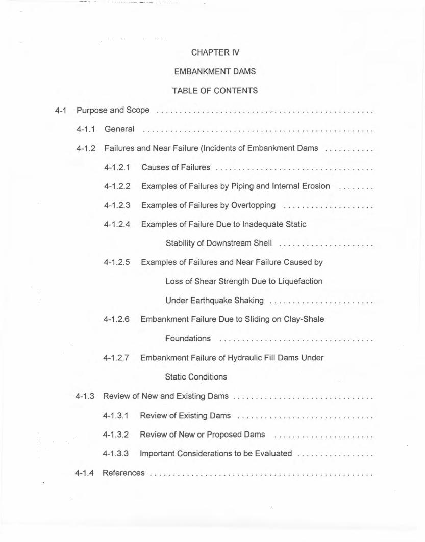
TABLE OF CONTENTS
4-1 Purpose and Scope " .
4-1 .1 General .
4-1.2 Failures and Near Failure (Incidents of Embankment Dams .
4-1.2.1 Causes of Failures .
4-1.2.2 Examples of Failures by Piping and Internal Erosion .
4-1.2.3 Examples of Failures by Overtopping .
4-1.2.4 Examples of Failure Due to Inadequate Static
Stability of Downstream Shell .
4-1.2.5 Examples of Failures and Near Failure Caused by
Loss of Shear Strength Due to Liquefaction
Under Earthquake Shaking .
4-1.2.6 Embankment Failure Due to Sliding on Clay-Shale
Foundations .
4-1.2.7 Embankment Failure of Hydraulic Fill Dams Under
Static Conditions
4-1.3 Review of New and Existing Dams .
4-1.3.1 Review of Existing Dams .
4-1.3.2 Review of New or Proposed Dams .
4-1.3.3 Important Considerations to be Evaluated .
4-1.4 References " .

4-2 Sources of Data and Information .
4-3 Review of Existing Data .
4-4 Need for Supplemental Information .
4-5 Evaluation of Embankment Dams ~ .
4-5.1 Embankment Zoning .
4-5.2 Seepage Control Measures .
4-5.3 Deformation, Predicted or Recorded .
4-5.4 Erosion Control Measures .
4-5.5 Structural Stability Analyses .
4-5.6 Potential for Liquefaction .
4.5.7 Soil Properties .
4-5.8 Embankment Overtopping Potential .
4-6 Static Stability Evaluation .
4-6.1 General .
4.6-2 Review Approach .
4-6.3 Conditions to be Investigated " .
4-6.4 Shear Strength .
4-6.4.1 Laboratory Testing .
4-6.4.2 Unconsolidated-Undrained Shear Strength
(UU or UC-type tests) ., .
4-6.4.3 Consolidated-Undrained Shear Strength
(CU- or CD-type tests) .

4-6.4.4 Consolidated-Drained Shear Strength
(CD-type tests) .
4-6.4.5 Residual Shear Strength .
4-6.5 Note on Types of Stress Analyses and Terminology .
4-6.6 Loading Conditions for Analysis and Selection of Shear
Strength Values .
4-6.6.1 End of Construction Loading Condition .
4-6.6.2 Rapid Drawdown Loading Condition .
4-6.6.3 Steady Seepage Loading Condition .
4-6.6.4 Partial Pool Loading Conditions .
4-6.7 Factors of Safety .
4-6.8 Static Stability Analyses .
4-6.9 Earthquake .
4-7 Seismic Stability Evaluation : .
4-7.1 General Approach " .
4-7.2 Modes of Failure: .
4-7.3 Methods of Analyses
4-8 R~fe~J.1C~ s

Chapter IV
Embankment Dams
4-1 Purpose and Scope
4-1.1 General
The guidelines presented in this chapter provide staff engineers with recommended
procedures and criteria to be used in reviewing and evaluating the safety of existing and
proposed earth and rockfill (embankment)dams. The review performed by staff engineers
will be conducted to ensure that all decisions, methods, and procedures performed by
Iicensees/exemptees, or their consultants, are sound regarding damsafety, and to ensure
that the Commission's Dam Safety Program objectives as stated in Part 12 of the
Commission's Regulations are consistent with accepted, up-to-date state-of the-art
procedures (the term licensees also refers to applicants for license where appropriate).
The evaluation of safety of both new and existing embankment dams presents
special and unique problems. Existing dams may prove difficult to analyze especially in
those instances where the dam was designed before the development of modern design
and construction technology or where adequate records are not available. Even for a
relatively new dam where records are extensive, evaluation can be cumbersome for the
following reasons: (a) various levels of completeness of records, (b) different site
conditions, (c) varying degrees of quality in design and construction, and (d) differing
depth of evaluation required for each dam.

2
One of the main objectives set forth in this chapter is to provide systematic state of
the art procedures for performing staff evaluations. It should be recognized however that
the various calculation procedures discussed herein are illustrated for a given mode of
failure for an embankment dam subjected to a given loading. Even though it is important
to correctly utilize the most current procedures to assess the degree of safety for a given
mode offailure, it has been established by study of case histories offailures that the cause
of many failures have been the result of omissions in considering all possible modes of
failure during design. The lack of foresight to provide appropriate zoning to preclude
certain modes of piping failure has also resulted in failures. Such appropriate intelligent
zoning provisions may not even require any engineering calculations. The selection ofthe
best zoning to control seepage for a given dam and foundation condition does require a
certain degree of alertness and an informed knowledge of the lessons learned from
precedent.
Failures have also resulted because of the use of inappropriate shear strengths for
static loads and the lack of appreciation of liquefaction potential during earthquakes for
dams resting in part on alluvial foundations or for dams composed of hydraulic fill
materials.
In the following section of this guideline, the causes of recent failures of embankment
dams are reviewed to emphasize the most important design considerations for
embankment dams. Incidents of near failure or inadequate performance are also cited to

- - - -. - -- - --- •• _ •• h-- -- . - -- - - - ---. -- - - - -- -- - -~ --
3
guide the reader in developing a checklist of important design considerations for use in
embankment dam design and inspection. A knowledge of precedent is a necessary tool
in the design and inspection of embankment dams. The calculation procedures given
herein on various topics should not be used by themselves without considering the
precedents of key embankmentdamfailures and the precedentsof key damdesigns which
have performed successfully. The knowledge and use of key precedents supplemented
by the calculation procedures given herein to arrive at an appropriate design of an
embankment dam represents a processes in which the results of engineering calculations
are tempered with judgement based on observations of the performance of other
embankment dams. This is the general way in which the art of embankment dam design
has developed in the past and is the appropriate way in which it can be improved in the
future.
4-1.2 Failures and Near Failure Incidents of Embankment Dams
4-1.2.1 Causes of Failures
A failure for the purpose of this discussion is an uncontrolled release of the reservoir
due to a breach of the embankment damn. An incident may be a near failure which was
averted by some combination of remediation and controlled reservoir lowering, most
usually as a result of keen observations of increased and uncontrolled seepage by
inspectors.
The most common causes of embankment dam failures are:

4
1) Piping by internal erosion of fine-grained soils from the embankment dam.
Piping through the foundations or abutments of the embankment dam.
Piping along conduits constructed through the embankment dam.
2) Overtopping of the dam and subsequent breach by erosion due to
overtopping. Overtopping has occurred due to inadequate spillway capacity
and due to improper operation of spillway gates. Overtopping and a breach
has also occurred on an upper reservoir of a pumped storage project without
a spillway.
Failures have also resulted from the following causeswhich are much less common.
3) Loss of shear strength due to high pore pressures and in some cases
liquefaction of loose saturated granular materials in the foundation or
embankment during earthquakes.
4) High pore pressures in downstream shell due to inadequate drainage
resulting in instability and failure of the downstream shell.
5) Embankment failure due to sliding on clay-shale foundations.
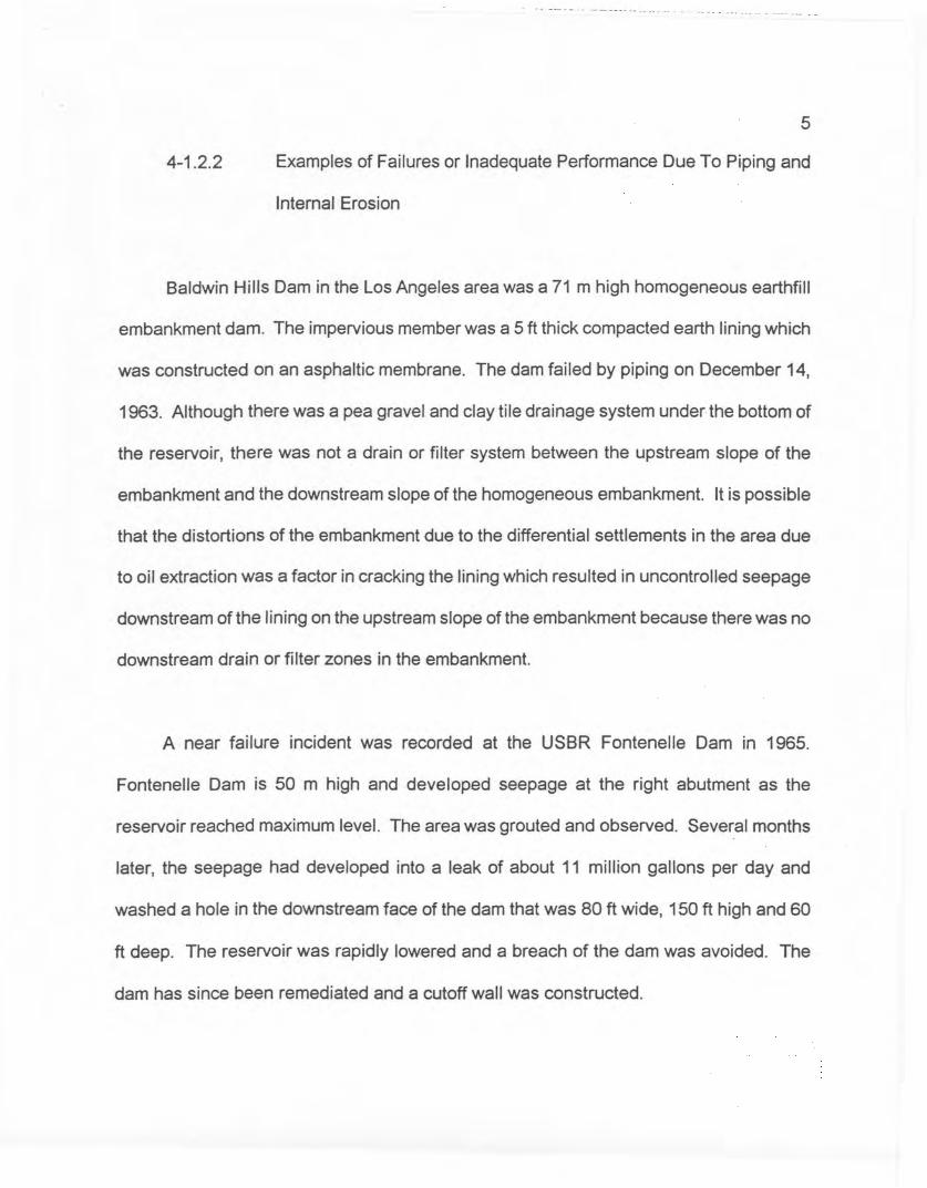
4-1.2.2
5
Examples of Failures or Inadequate Performance Due To Piping and
Internal Erosion
Baldwin Hills Dam in the Los Angeles area was a 71 m high homogeneous earthfill
embankment dam. The impervious member was a 5 ft thick compacted earth lining which
was constructed on an asphaltic membrane. The dam failed by piping on December 14,
1963. Although there was a pea gravel and clay tile drainage system under the bottom of
the reservoir, there was not a drain or filter system between the upstream slope of the
embankment and the downstream slope of the homogeneous embankment. It is possible
that the distortions of the embankment due to the differential settlements in the area due
to oil extraction was a factor in cracking the lining which resulted in uncontrolled seepage
downstream of the lining on the upstream slope of the embankment because there was no
downstream drain or filter zones in the embankment.
A near failure incident was recorded at the USSR Fontenelle Dam in 1965.
Fontenelle Dam is 50 m high and developed seepage at the right abutment as the
reservoir reached maximum level. The area was grouted and observed. Several months
later, the seepage had developed into a leak of about 11 million gallons per day and
washed a hole in the downstream face of the dam that was 80 ft wide, 150 ft high and 60
ft deep. The reservoir was rapidly lowered and a breach of the dam was avoided. The
dam has since been remediated and a cutoff wall was constructed.
- -- - -. - -- - - --- -- - -- -- -. -- - -- - - ------ - -
6
In February 1975 the .Walter Bouldin Dam in Alabama failed. The 165 ft high
embankment dam just to the left of the powerhouse breached. As described by Leps
(1988) this location is where a cretaceous fine sandy silts could have piped undetected
into the tailrace channel from seepage lines in the foundation of the left embankment dam
as there was no cutoff to bedrock beneath the left embankment dam immediately adjacent
to the left side of the tailrace channel. These seepage lines were not filtered in the design
and could have exited into the tailrace channel below water level where the piping would
have been uninspectable. Two independent engineering panels wrote reports on the
possible cause of this failure. One panel indicated that the most probable cause was an
upstream slope stability failure. Another group indicated that it was most probably piping
in the unprotected cretaceous fine sandy silts, in the left embankment dam foundation.
Leps, 1988 makes a compelling case for the piping mode of failure.
On June 5, 1976 the 126 m high Teton Dam of the USBR failed during first filling,
which had been initiated in October 1975. The failure of Teton Dam was a clear'Case of
piping because the silt core in the rock cutoff trench in the right abutment was directly
placed against open jointed rhyolite without a filter between the silt and the jointed rock.
This case history has been described many times. Leps, 1988, and Sherard, August 1983.
Even this very clear case of piping has been described by Hilf, August, 1995, and Fucik,
August, 1985, as due to other causes. These interpretations cited above indicate how
misinterpretations of case histories has the potential to set back the state of the art if there
is only one small group commenting on a case history where a failure occurred.
7
On October 30, 1979 the Martin Co. Embankment Dam impounding a cooling pond
for the Florida Power and Light, Martin Co. oil fired power plant failed by piping. This
failure was 18 months after filling and occurred just 2 days after a lowering of the water
level in a canal just downstream of the embankment. The canal water lowering increased
the gradients through the foundation of the dam which was founded on fine sands. The
dam did not have a cutoff and had a homogeneous fine sand crossection with no filter
drain system. The dam had an upstream soil cement member to act as a rip-rap to protect
the sand embankment from erosion (Swiger, Hendron, Shae and Smertmann, July, 1980).
The sands in the foundation could have piped to a borrow pit immediately downstream of
the toe of the embankment after the tailwater was lowered because there was no filter
placed on the sides of the borrow pit to prevent migration of the fine sand foundation
materials and the seepage outlet could have been below the borrow pit water surface
where evidence of transported materials could not have been observed during inspections.
In addition to the above cases, there have been two recent cases of piping of blanket
materials into natural alluvium which served as a foundation for the blanket. In both cases
the blankets were used to replace a cutoff and there was no filter placed in between the
blanket and the natural alluvial material on which the blankets were placed.
In one case, Tarbela Dam, a 40 foot thick blanket was placed on top of river alluvium
and there was 450 feet of head which could result in a vertical gradient of about 10
through the blanket without a filter protecting the blanket. When the reservoir was lowered
- --- -- --- -+- - - ----- --._- - ----
8
because of other problems on the project hundreds of sinkholes in the blanket were
observed and had to be monitored and filled with well graded materials by dumping from
barges during the next filling. This case is discussed by Lowe, 1998.
Sinkholes were also observed at the Ludington Pumped Storage Project where a two
foot thick blanket was used over natural glacial fluvial materials without a filter between the
blanket and the foundation. For this case the vertical gradients through the blanket were
on the order of 50. These two cases represent the omission of a filter on the underside
of the blanket and did not involve the details of filter criteria.
4-1.2.3 Examples of Failures by Overtopping
On the Pedro River, San Paulo, Brazil, two earth dams (Euclides de Cunha and
Armando Salles de Oliviera) were overtopped and destroyed on January 19, 1977 (Water
Power, 1977). An area of 250 km2 downstream of the damns was inundated with
considerable loss of property. It is reported that the 10,000 year flood developed in the
basin.
Buffalo Creek Dam in West Virginia failed on February 26, 1972 by overtopping
resulting from inadequate spillway capacity, and 118 people were killed. The dam was
built from mine wastes.
4-1.2.4
9
Examples of Failure Due to Inadequate Static Stability of Downstream
Shell
On Auguyst 27, 1993 a Concrete Faced Dam failed in China (Gouhou Dam) one day
after the reservoir level reached the top of the slab. The failure was due to failure of the
gravel shell. Although many CFRD's have been built from freely draining rock fill and
clean gravels with no stability problems with slopes ranging from 1.3 to 1.6: 1, this
particular dam had a 1.5: 1 downstream slope, but it was constructed with sandy gravels
with about 40% of the particles finer than 5 mm. With the leakage through the face and
perimeter joint, the dirty shell materials were not pervious enough to conduct the flow at
low gradients and a phreatic surface raised high enough in the shell that the normal CFRD
slopes could not be maintained, ,and the dam failed. The failure should have not been a
surprise.
4-1.2.5 Examples of Failures and Near Failure Caused by Loss of Shear
Strength Due to Liquefaction Under Earthquake Shaking
On February 9, 1971 a strong earthquake (6.6 Richter Magnitude) occurred with an
epicenter about 8 miles northeast of Lower San Fernando Dam, California. The
embankment, with a height of 142 feet was originally constructed in 1921 as a semi
hydraulic fill. The earthquake caused the development, towards the end of the earthquake
shaking, of very high pore pressures in an extensive zone of hydraulic fill near the base
----- _u 0_. . ..
10
of the embankment and upstream of the clay core so that much of this soil was in a
liquefied or very low strength condition. A comprehensive dynamic analysis of the failure
has been described by Seed, et al (1975). Fortunately, the reservoir storage at the time
of the event was only slightly more than half full so that no water overtopped the dam and
no leaks developed. Had the reservoir been filled only several feet higher, a major
catastrophe might have resulted in the densely populated downstream communities.
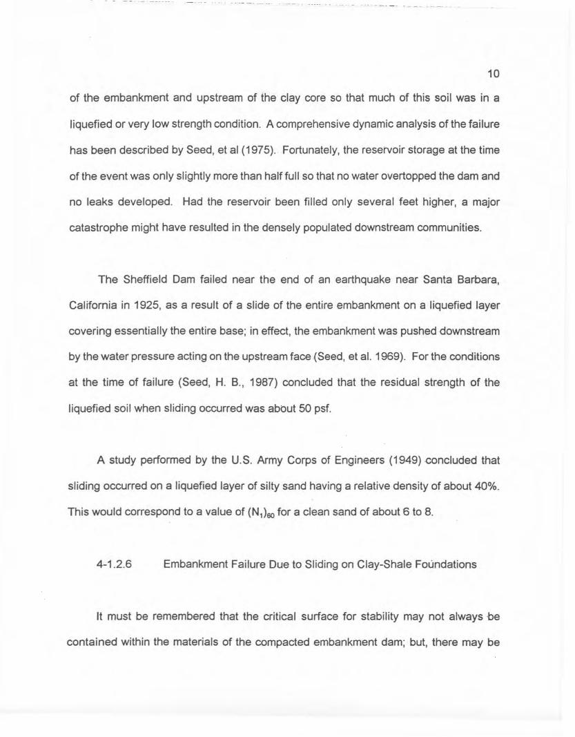
The Sheffield Dam failed near the end of an earthquake near Santa Barbara,
California in 1925, as a result of a slide of the entire embankment on a liquefied layer
covering essentially the entire base; in effect, the embankment was pushed downstream
by the water pressure acting on the upstream face (Seed, et al. 1969). For the conditions
at the time of failure (Seed, H. B., 1987) concluded that the residual strength of the
liquefied soil when sliding occurred was about 50 psf.
A study performed by the U.S. Army Corps of Engineers (1949) .concluded that
sliding occurred on a liquefied layer of silty sand having a relative density of about 40%.
This would correspond to a value of (N1)60 for a dean sand of about 6 to 8.
4-1.2.6 Embankment Failure Due to Sliding on Clay-Shale Foundations
It must be remembered that the critical surface for stability may not always be
contained within the materials of the compacted embankment dam; but, there may be
----- ----- ---------- - -- - -- -- - -~ -. -- --.- -. ---- -.--- -- - - -- .-- .------ - -- -- - - --.-
11
preferred weak planes in the foundation which may control, particularly when the
foundations are horizontally bedded plastic clay shales.
In 1963 the Corps of Engineers had such a stability failure at Waco Dam during
construction. The dam was placed on the Pepper Shale Formation and failure took place
on a bedding plane with zero cohesion and a low effective angle of shearing resistance.
Fortunately the event occurred before the reservoir was filled.
In 1971 a berm was deemed necessary at Standley Lake Dam at Westminster,
Colorado because of downstream movements of the slope. The foundation of the dam is
on cretaceous shales and the movements stopped with the addition of the berm. This case
is certainly not a failure, but a case where the Factor of Safety was marginal and spreading
was occurring on weak beds in the horizontally bedded Cretaceous clay shale formations.
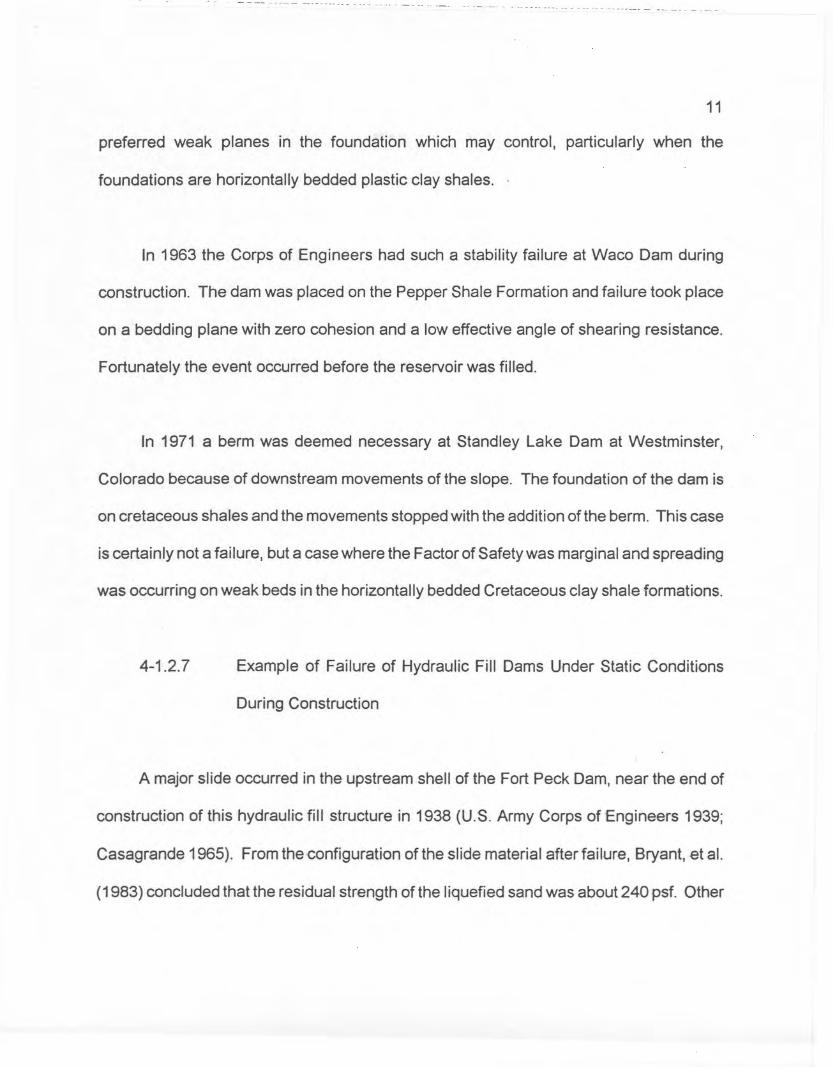
4-1.2.7 Example of Failure of Hydraulic Fill Dams Under Static Conditions
During Construction
A major slide occurred in the upstream shell of the Fort Peck Dam, near the end of
construction of this hydraulic fill structure in 1938 (U.S. Army Corps of Engineers 1939;
Casagrande 1965). From the configuration of the slide material after failure, Bryant, et al.
(1983) concluded that the residual strength of the liquefied sand was about 240 psf. Other

12
studies indicate a pre-sliding driving stress of about 700 psf; a reasonably conservative
value is probably about 600 psf.
It is believed that, in this case, the slide occurred due to liquefaction of sand in the
foundation. Studies made by the U. S. Army Corps of Engineers, both soon after the slide
occurred and during a re-evaluation of the stability of the dam in 1976 (Marcuson and
Krinitzsky 1976), indicate that the relative density of the sand was probably about 45 to
50%. This would correspond to a value of (N1)60 for a clean sand of about 12.
A liquefaction-type slide occurred in the upstream shell of the Calaveras Dam as it
approached a height of 200 ft in 1918 (Hazen 1918). The dam was a hydraulic fill
structure, and it was subsequently reconstructed using rolled fill construction. From the
configuration of the slide mass, the residual strength of the liquefied sand is estimated to
be about 750 psf, and tests performed in recent years show that the SPT (N1)60 value for
the hydraulic sand fill in the original structure was probably about 12.
4-1.3
4-1.3.1
Review of New or Existina Dams
Review of Existing Dams
The review of existing dams will generally not be as detailed as the procedures
involved in the design of new dams. Some critical areas may require detailed review.
Primarily, the review is intended to evaluate the design, analysis and observ.ed behavior

13
to ensure that safe and adequate embankment dams were constructed. The licensee's or
its consultant's investigations and evaluations should be examined to determine if all areas
of importance were considered and that appropriate design criteria have been used.
Existing dams should be viewed in light of knowledge of studies and reports on
similar dams of the same vintage to gain an understanding of probable design and
construction methods. For existing dams, an independent analysis of the embankment
stability or adequacy need not necessarily be performed by staff. The data presented by
the licensee should be reviewed to determine if they appear reasonable and if the latest
information has been considered. The criteria used by the licensee or its consultant
should be consistent with any changed conditions discovered during onsite examinations
such as loadings, increased seepage, increased pore pressures in the dam or the
foundation, erosion etc.
4-1.3.2 Review of New or Proposed Dams
For proposed dams, an analysis of the stability and adequacy is required unless
specifically exempted by the Commission. The methods and procedures used in the
evaluation of any embankment should be consistent with the latest, accepted state-of-the
art methods and criteria, and with guidance contained in this chapter of the guidelines.

14
For proposed or new dams, the licensee will be required to submit a design report
in accordance with the Commission's Regulations. His report will be thoroughly examined
to determine if all appropriate design criteria have been met.
4-1.3.3 Important Considerations to be Evaluated
During the investigation and evaluation for both proposed and existing dams,
important areas to consider are as follows:
The embankment must be safe against overtopping by wave action for all
operational conditions and the inflow design flood conditions.
The slopes must be stable during all conditions of reservoir operations, including
rapid drawdown, if applicable.
Seepage flow through the embankment, foundation, and abutments must be
controlled so that no internal erosion (piping) takes place and there isno sloughing
in areas where seepage emerges.
The embankment must not overstr.ess the foundation. Sliding stability of clay-shale
foundations must be evaluated.

15
Embankment slopes must be acceptably protected against erosion by wave action
and from gullying and scour against surface runoff.
The embankment, foundation, abutments and reservoir rim must be stable and must
not develop unacceptable deformation under earthquake conditions.
The potential for liquefaction of loose alluvial foundations or old hydraulic fill
embankments under earthquake must be considered.
Embankment deformations during earthquake shaking; and, post earthquake stability
must also be considered.
4-1.4 References
Criteria and methods of evaluation and analysis used in reviewing licensee's reports
should be based on the guidelines given herein and on criteria and procedures established
in literature published by such agencies as the Corps of Engineers, U. S. Bureau of
Reclamation, or other recognized engineering references. Selected references are listed
in Section 4-8.

16
4-2 Sources of Data and Information
To properly evaluate all information and data presented in the licensee's design
report or the licensee's existing dam, various available FERC reports should be reviewed.
Available reports include:
Pre-license Inspection Reports of existing dams and/or Site Inspection Reports of
proposed damsites
Operation Reports
Construction Reports
Independent Consultant's Safety Inspection Reports
One or more of the reports listed above should typically be available for licensed
projects. If a license has not previously been issued, the staff engineer performing the
review should refer to the Pre-license Inspection Report prepared by the staff engineer
responsible or the project in the Regional Office.
For existing dams, additional data may be available from the facility owner, previous
owners, state or local agency if the facility is a publicly owned project, and from the state
agency responsible for dam safety, such as Department of Water Resources, Department
of Environmental Resources, Division of Dam Safety or Department of Natural Resources.
Technical information may also be avai.lable from Corps of Engineers Phase I Inspection

17
Reports of public or private entities having impounding structures upstream or downstream
of the facility.
For proposed dams, the source of information will generally be the licensee and/or
its consultants and engineers. For all proposed dams, the licensee will be required to
provide staff with those data necessary to evaluate whether the design of the structure is
safe and adequate.
Data that may be available from the sources referenced should include:
Summary statement of precedents for similar dams
Logs of drill holes, test pits, and exploratory trenches
Site geologic reports
Site seismicity reports
Materials exploration and testing reports
Reservoir area-capacity curves, rim conditions, and drainage basin information
Dambreak analyses and reports
Construction reports
Correspondence that may highlight design changes or problems
Design drawings and specifications
Design reports including assumptions used and the reasons therefore for the
assumptions

18
Inspection records
Maintenance records
Aerial photography
Licensee's reports
Construction photographs
Concrete materials and mix design
As built drawings
Cross-sections showing embankment, cutoff, foundation, geology, piezometric
levels, and the location of other instruments, such as inclinometers.
4-3 Review of Existinq Data
Appendix 4-A is a listing of various engineering data related to the design,
construction, and operation of an embankment dam. Prior to review and analysis of
existing data, this appendix may be useful in organizing the data as discussed in the U.S.
Bureau of Reclamation's "Safety Evaluation of Existing Dams (SEED) Manual" (Ref. 2)
The engineer performing the review should examine all data to determine if problem
areas have been recognized and, if appropriate methods are proposed for correction.
Additionally, the data should be examined to determine if the source of any current
conditions or problems, such as seepage, settlement, cracking, etc., are evident from

19
existing data. The methodologies and criteria used in the design should be examined and
compared to accepted state-of-the-art procedures and criteria.
Advances in accepted state-of-the-art methodologies may require a reevaluation of
the original design by use of these guidelines. The SEED Manual discusses in greater
detail specific information to look for in the reports and data that may be available.
4-4 Need for Supplemental Information
The objective of reviewing existing data is to be able to use as much information as
is available to evaluate the structural adequacy of existing or proposed embankment dams.
Data and analyses should be the prevalent basis for judgments on dam' safety. If
potentially hazardous conditions are believed or determined to exist, and the existing data
are insufficient to resolve the problem, it may be necessary to request supplemental
investigations, analyses, or information to complete the evaluation. The supplemental
information could involve additional visual inspections, measurements, foundation
exploration and testing of materials, seismic information, and hydrologic and ~ydraulic
data. Conditions that may require supplemental information are as follows:
Significant cracking, settlement or sloughing of an existing embankment and the
potential for such in any propos'ed structure

20
Uncontrolled seepage conditions through or under the embankment, the abutments,
or at the toe area, and the potential for such in any proposed structure. Areas
deserving intense scrutiny are those embankments founded over alluvium without
a cutoff to bedrock.
Available data is not adequate to perform accepted state-of-the-art analyses that are
necessary
Increase in settlement rate or horizontal movement rate either upstream or
downstream
Increases or decreases in measured seepage quantities
Rises in internal pore pressures
4-5 Evaluation of Embankment Dams
The two principal types of embankment dams are earth dams and rock-fill dams,
depending on the predominant fill material used.
a. Earth Dams - An earth dam is composed of suitable soils obtained from borrow
areas or required excavation which are then spread and compacted in layers by
mechanical means. Earth dams have been constructed as both homogeneous or
zoned dams.
21
Zoned dams are generally preferred since zoning incorporates the use of drains and
filters in the embankment to control seepage. Homogeneous embankments without
a chimney drain and filters are usually not considered acceptable in new modern
construction, but many dams of this type are in service and must be inspected and
monitored very carefully.
Some older dams have been placed by hydraulic means. These hydraulic fill dams
frequently contain large masses of loose to very loose soils in them because of the
dumping and sluicing of the soils during construction. Adequate soil data (e.g. SPT
blow counts, gradation analysis, phreatic surface, etc.) must be available to evaluate
the liquefaction potential and stability of these dams.
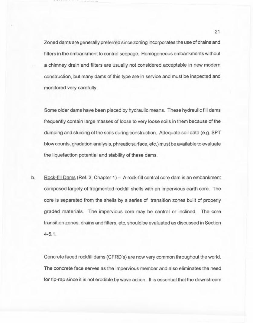
b. Rock-fill Dams (Ref. 3, Chapter 1) - A rock-fill central core dam is an embankment
composed largely of fragmented rockfill shells with an impervious earth core. The
core is separated from the shells by a series of transition zones built of properly
graded materials. The impervious core may be central or inclined. The core
transition zones, drains and filters, etc. should be evaluated as discussed in Section
4-5.1.
Concrete faced rockfill dams (CFRD's) are now very common throughout the world.
The concrete face serves as the impervious member and also eliminates the need
for rip-rap since it is not erodible by wave action. It is essential that the downstream
------_ ---0 __ ._._. _
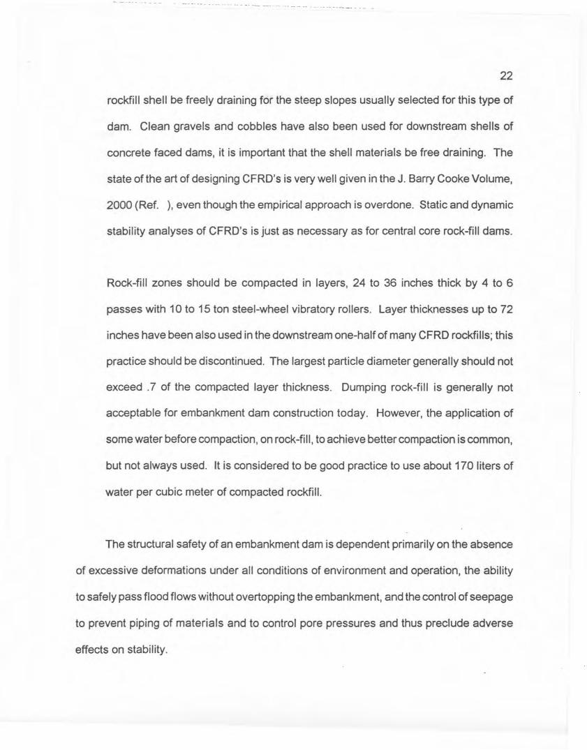
22
rockfill shell be freely draining for the steep slopes usually selected for this type of
dam. Clean gravels and cobbles have also been used for downstream shells of
concrete faced dams, it is important that the shell materials be free draining. The
state of the art of designing CFRD's is very well given in the J. Barry Cooke Volume,
2000 (Ref. ), even though the empirical approach is overdone. Static and dynamic
stability analyses of CFRD's is just as necessary as for central core rock-fill dams.
Rock-fill zones should be compacted in layers, 24 to 36 inches thick by 4 to 6
passes with 10 to 15 ton steel-wheel vibratory rollers. Layer thicknesses up to 72
inches have been also used in the downstream one-half of many CFRD rockfills; this
practice should be discontinued. The largest particle diameter generally should not
exceed .7 of the compacted layer thickness. Dumping rock-fill is generally not
acceptable for embankment dam construction today. However, the application of
some water before compaction, on rock-fill, to achieve better compaction is common,
but not always used. It is considered to be good practice to use about 170 liters of
water per cubic meter of compacted rockfill.
The structural safety of an embankment dam is dependent primarily on the absence
of excessive deformations under all conditions of environment and operation, the ability
to safely pass flood flows without overtopping the embankment, and the control of seepage
to prevent piping of materials and to control pore pressures and thus preclude adverse
effects on stability.

23
To properly evaluate the stability of an embankment dam, the following areas should
be reviewed.
Embankment zoning and cross section
Seepage control measures (Drains and filters) to control pore pressures and to
preclude piping.
Deformation, predicted and measured
Erosion control measures such as bedded rip rap and filters to control piping by
backward erosion.
Structural stability analyses
Liquefaction potential
Overtopping potential and the ability to resist overtopping
Foundation and embankment material properties and strengths
Adequacy of freeboard
For existing dams, thereview should also include summarizing the past behavior of
the dam, with attention given to any problem areas noted, changes in measured seepage,
changes in measured pore pressures, changes in measured settlements and horizontal
movements.

-._--- .--- - -- - -.- -- ~- -- - -- - ---
24
4-5.1 Embankment Zoninq
For zoned embankments, the zoning geometry and properties of the materials placed
in the zones should be reviewed to determine: (1) the structural design, and (2) the types
of internal features such as chimney drains, blanket drains, toe drains, etc., that are
proposed or were used to provide for and maintain embankment stability. One should
keep in mind that embankment zoning is also established for economic reasons according
to the availability of materials (Ref. 1, Chapter 6). The embankment zoning should provide
an adequate impervious zone, filter and drainage zones between the core and the shells,
and seepage control zones. Desirable characteristics that these zones should have or
provide are as follows:
In general, the width of the core at the base of cutoff should be equal to, or greater
than, 25 per cent of the maximum difference between the maximum reservoir and
minimum tailwater elevations. The minimum top width of the core should not be less
than 10 feet (Ref. 3, pg. 5-3). The coefficient of permeability 'Ofthe core material
should preferably be 10-4 em/see or less. More permeable core material may be
acceptable if seepage is adequately controlled and appropriate factors of safety are
still met (Ref. 1, Chapter 6).
Transition zones must meet accepted filter criteria, e.g. see References 1, 4, & 5,
to protect the adjacent zones from piping. The transition zones should be sufficiently
25
wide to ensure that they are continuous and constructable with a minimum of
contamination at the contact (Ref 4, pg. 57,607; Ref. 1, Chapter 6). The range of
gradation of the transition zones should be limited to avoid segregation of materials
during placement.
Seepage control features such as pervious drains within the embankment should be
sized adequately to contain all seepage flows. The features should also be
sufficiently pervious to ensure that all seepage will be intercepted and controlled
without excessive pressure head losses (Ref. 1, Chapter 6, Ref. 3, pg. 5-3).
Zoning of an embankment that places the more pervious material on each side of
the core zone is preferable. This placement improves the stability of the
embankment during rapid drawdown conditions and keeps the downstream slope
drained for greater effective weight (Ref. 5, pg. 7). It is conservative to utilize a filter
material on the upstream site of the core to act as a potential crack stopper.
Homogeneous dams should also have seepage control features such as chimney
drains, blanket drains, etc., including a filter zone between the main embankment material
and the drain. Desirable characteristics listed above also apply to the features of this type
of structure. The homogeneous structure is generally more massive and usually has flatter
slopes than a zoned embankment of the same height. These characteristics compensate

26
for a tendency toward a higher phreatic line in the homogeneous embankment. They also
tend to provide better slope stability during rapid drawdown (Ref. 1, Chap. 6).
4-5.2 Seepaqe Control Measures
All embankment dams are subject to some seepage passing through, under, and
around them (Ref. 5, pg. 1). If uncontrolled, seepage may be detrimental to the stability
of the structure as a result of excessive internal pore water pressures or by piping (Ref.
3, pg. 1-6). For existing dams, records or evidence that seepage flows have removed any
significant degree of fine grained material must be evaluated. Any such records requires
further field investigation.
Seepage discharge should be effectively controlled to preclude structural damage
or interference with normal operations.
In the evaluation of seepage reduction or seepage control measures as they pertain
to dam safety, one should review and evaluate the following:
Protective control measures such as relief wells, weighted graded filters, horizontal
drains, or chimney drains which prevent seepage forces from endangering the
stability of the downstream slope (Ref. 3, p. 1-6).

27
Filters and transition zones designed to prevent movement of soil particles that
could clog drains or result in piping (Ref. 4, pg. 57; Ref. 1, pg. 218).
Drainage blankets, chimney drains, and toe drains designed to ensure that they
control and safely discharge seepage for all conditions. The design of these
features must also provide sufficient flow capacity to safely control seepage through
potential cracks in the embankment impervious zone (Ref. 3, pg. 1-6).
Contacts of seepage control features with the foundation, abutments, embedded
structures, etc., designed to prevent the occurrence of piping and/or hydrofracturing
of embankment and foundation materials (Ref. 1). If conduits or pipes exist through
the embankment, they should be inspected to insure that they are functional or have
been properly sealed. If there is the slightest doubt about through going conduits,
they should be decommissioned and replaced.
Grouting, cut-off trenches, and impervious blankets. The use of impervious blankets
or new structures in place of a cutoff is discouraged because of piping of the blanket
materials into the foundation on recent projects. Blankets should only be used as
a last resort element; and, then the use ofa filter between the blanket and the
foundation must be evaluated, not immediately omitted.

--.----.-- ------. ~.._-- -------------
28
Construction records for foundation shaping, treatment and grouting at the contact
between the impervious core and foundation.
Measures such as compaction requirements, seepage collars, placement of special
materials, or other similar features to prevent internal erosion from seepage at the
interface with concrete structures (Ref. 1). If seepage collars are present, special
attention should be given to compaction requirements around them. The use of
seepage collars is not recommended in new construction.
For existing embankments, all seepage records compiled during the existence of the
structure should be reviewed for significant trends or abnormal changes. The
causes of any abnormalities should be determined as accurately as possible.
As indicated in the introductory remarks to this chapter, piping by backward erosion
is one of the most common causes of embankment dam failures. The keys to controlling
seepage to preclude piping are 1) the placement offilter over seepage exits from erodible
soils to prevent migration of the erodible or pipeable soils; and, 2) the gradation of the
filters must be appropriate to prevent migration of the erodible material into the filter, and
the filter must not migrate into the drain or the bedrock downstream of the filter. It is
indeed sobering that the piping failures cited at the beginning of this chapter were cases
where the appropriate filter zones were absent due to omission of considering all possible
seepage paths along which piping could occur. In many existing dams there are unfiltered

- -- - n . _____ n • _. _
29
seepage outlets which are uninspectable because they are located under the tailwater on
the downstream side of the dam. An additional consideration, once it is decided to place
filters at the appropriate locations, is that the filter and drain, or multiple filters be graded
to serve the intended purpose of protecting the erodible materials and that the filters and
drains be placed without segregation. In this respect, it has been established in a recent
years that the original Terzaghi filter criteria is not appropriate for the protection of well
graded or gap graded materials. A more complete discussion of filters is given in
Appendix 4-8.
4-5.3 Deformation. Predicted or Recorded
The type, amount, and rate of deformation of an embankment either vertical or
horizontal movement, should be estimated during the design stage and must be recor-ded
during the operation of the structure. For proposed embankments, the struc{ure should
generally be cambered to allowforthe estimat.ed settlement during the life of the structure .
. For existing embankments, any evidence or records of unusual settlement, cracking, or
movement should be reviewed to determine whether these conditions are detrimental to
the continued safe operation of the structure. Field investigations may be required to
determine the causes of these abnormalities. These investigations may involve such items
as surveying the structure, installing movement detecting instruments, or excavating test
pits for examination (Ref. 4, Chapter 12). The embankment history, height, f.oundation
30
conditions, hazard, etc. are factors to be considered in determining field investigation
needs.
As a result of deformation, cracking can develop through the impervious core section
below the line of saturation which may result in piping. Adequately sized and graded filter
and drain zones located downstream from the impervious core can prevent piping (Ref.
4, Chapter 11). A filter crackstopper on the upstream side of the core is also a useful zone
to control seepage in the event of core cracking. Corrective measures may be needed if
adequate filter zones do not exist or are not correctly located.
4-5.4 Erosion Control Measures
Upstream and downstream slopes, the toe area, groin areas of the abutments,
approach and discharge channels, and areas adjacent to concrete structures should be
protected against excessive erosion from wave action, surface runoff, and impinging
currents. Inadequate erosion protection can result in slope instability (Ref. 3, Chapter 5).
Some common types of protection used are riprap, gabions, paving (concrete or asphalt),
and appropriate vegetative cover.
The slope and toe protection of all embankment dams should -be reviewed to
determine if the dam is adequately protected against erosive forces. If the slope protection
is being continually displaced, heavier protection is required. Additionally, if embankment

31
materials, consisting of silty and sandy soils, are being moved into the slope protection,
measures must be taken to correct this condition before erosion becomes detrimental to
the embankment. If riprap is required, a bedding layer must be designed according to
established filter criteria and placed under the riprap protection (Ref. 1, Chapter 6).
4-5.5 Structural Stabilitv Analvses
The evaluation of the stability of embankment dams shall be based on the available
design information for proposed structures and on design and construction information and
records of performance for existing embankments. The Corps of Engineers Guidelines for
Safety Inspection of Dams (Ref. 6) can be used as a guide in performing the review.
Stability studies and analyses for proposed embankments will be conducted during
design in accordance with methods discussed in Section 4-6.8. Quality control testing
during construction will be used to confirm that the design values are being achieved. For
existing embankments, the initial stability studies and analyses will normally be acceptable
if they were performed by approved methodologies and ifobservations of the performance
during reservoir operation do not suggest potential instability. It is also very important to
check the design slopes against previous precedent for similar dams, in spite of the
calculations. Be especially suspicious and check all assumptions when the design
calculations yield a slope steeper than normal precedent. Additional stability analyses
should be performed if initial design analyses do not exist or are incomplete, if existing

--. ----· 0 +
32
conditions have deteriorated, if hazard potential of the project has increased, if the
embankment has been subjected to loading conditions more severe than designed for, if
existing analyses are not in agreement with current accepted state-of-the-art
methodologies, or if assumed design parameters cannot be satisfactorily justified.
Satisfactory behavior of the embankment under loading conditions not expected to be
exceeded during the life of the structure should generally be indicative of satisfactory
stability, provided adverse changes in the physical condition of the embankment have not
occurred (Ref. 6, pg. 10).
Evidence of any adverse changes which could affect the stability of an embankment
may be obtained from visual inspection and observation of available instrumentation data
covering such items as changes in pore water pressures, displacements, changes in
loading conditions, seepage, etc. Review of maintenance records and related information
may also provide a reference to structural behavior data for a particular structure. Should
a review of project records indicate possible deficiencies in the stability of an embankment,
additional information may be required regarding the foundation and embankment
materials. The Corps of Engineers Guidelines for Safety Inspection of Dams (Ref. 6, p.
10) and other available literature (Ref. 3, Ref. 5, Ref. 7, Ref. 8, Ref. 9,k Ref. 10, Ref. 15)
can be referred to in establishing the information necessary to determine the condition and
material properties of the foundation and embankment.

----.- - - --- -- - -" - ------- ..... - - -- -- - - -.- ..- ---.
33
4-5.6 Potential for Liquefaction
The phenomenon of liquefaction of loose saturated sands, gravels, or silts having
a contractive structure mayoccur when such materials are subjected to shear deformation
with high pore water pressures developing, resulting in a loss of strength or resistance to
deformation.
The potential for liquefaction in an embankment or its foundation must be evaluated
on the basis of empirical knowledge and engineering judgment supplemented by special
laboratory tests when necessary. The current state of the art for evaluation soil
liquefaction potential is by using the standard Penetration blow counts to estimate the
cyclic strength ratio of the sand and to compare the cyclic strength ratio with the cyclic
stress ratio induced by the earthquake motions. The cyclic strength-blow count
relationships have been established from case histories (Ref. 12). The induced cyclic
stress ratios can be calculated by the simplified method or by the use of computer
programs to calculate the induced dynamic shear stresses more accurately. Further
discussion of liquefaction is presented in Section 4-7.
4-5.7 Soil Properties
Soil properties including strength and seepage parameters to be used as input data
for stability analyses should be realistic and representative of the range and variation that

.-- -- - - - • n_ n" ._ • __ ----._-~- ----
34
exist in the foundation abutment, and embankment materials (Ref. 14). For information
concerning the characteristics and strengths of foundation and embankment soils and
rock, refer to the procedures established in the Corps of Engineers and U.S. Bureau of
Reclamation Guidelines (Ref. 8, Ref. 9, Ref. 2, Ref. 15), and other literature {Ref. 16, Ref.
4, Ref. 17, Ref. 34). The selection of the proper input parameters and their correct use in
a stability analysis are generally of greater importance than the specific method of stability
analysis used.
4-5.8 Embankment Overtoppinq Potential
All embankment dams, either proposed or existing, should be evaluated for
overtopping potential under the most extreme conditions expected for which the dam is
determined to be a hazard to life or property. Chapter 2 of these Guidelines discusses the
Spillway Design Flood and provides freeboard criteria. The maximum reservoir elevation
determined for the design flood and expected wave runup are conditions that should be
considered. However, a less severe storm with lower reservoir elevation but greater wave
propagation may result in conditions that are more critical than those produced by the
design flood. In general, overtopping of an embankment dam is not acceptable. It is not
considered acceptable to prevent overtopping, for operational flows, by routinely storing
water against a parapet wall on the crest of an embankment.

35
4-6 Static Stability Evaluation
4-6.1 General
As discussed in Section 4-1.2, a new, independent stability analysis by staff is not
necessarily required for a proposed or existing embankment. Spot checks of analyses
may be required to verify that application of the specific analytical approach is correct.
The analysis and evaluation of the structural adequacy of an embankment dam by the
licensee and/or its consultant should be reviewed based on information formulated by the
licensee and information developed by the Regional Office staff from various project
inspections and data requests resulting from the licensing or inspection program. For
embankment dams, stability analyses should be examined to determine if the criteria used
and loading conditions analyzed are appropriate. This review should be based on the
above information to determine if the methods of analyses used are based on accepted
state-of-the-art and that proper types offailure surfaces have been analyzed (e.g., wedge,
circular, or noncircular).
An independent stability analysis should be performed by staff if actual conditions
differ from those assumed in the licensee's analysis, if soil parameters are inconsistent
with material types, if soil strength parameters or pore water pressures are inconsistent
with the method being used, or if the critical failure surfaces do not appear to have been
determined. The staff should always compare the selected design slopes of the dam in

36
question with precedent from dams composed of similar materials on similar foundations.
If the slopes of the dam in question are significantly steeper than precedent, then the
assumptions and mechanics of the design calculations must be checked in detail by the
staff.
Staff has several stability programs for computers available (Ref. 37 and 38). These
programs may be used by staff in reviewing the results of the licensee's analyses. It
should, however, be understood that the results obtained by these methods of analyses
may not necessarily agree exactly with the licensee's results based on another method;
however, it will provide an indication as to the adequacy of the analysis being reviewed.
Staff is not limited to the use of these computer programs. Other accepted programs may
also be used. The staff should verify that the licensee has checked the analysis by hand
calculations for potential critical cases that have marginal factors of safety. The staff
should also perform hand calculations on the critical surface as an independent check.
References are listed in Section 4-8 that analyze the various methods of stability
analyses in detail. An historical development of methods of stability analyses is presented
in Reference 16 (pp. 323-326).

37
4.6-2 Review Approach
Stability analyses should be reviewed to determine if input <:fataappear appropriate
based on a knowledge of the embankment and foundation materials, on pore pressures
in the embankment and its foundation, or if the method of analysis chosen by the licensee
is being used correctly. The literature provides several publications, textbooks, and other
sources of information that discuss in detail the various methods of analyses available.
Refer to Section 4-8 for references that can be used to obtain information for use in
reviewing a particular method of stability analysis (Ref. 20, Ref. 26).
A review of the stability analyses presented by the licensee shall include an
evaluation and summary of the data used in the analysis and an evaluation to determine
if the critical conditions have been investigated. The items to be evaluated include:
Densities of soils
Shear strength parameters
Pore water pressures, estimated or measured
Loading conditions
Trial failure surfaces
Method of analysis

38
The soil densities and shear strengths to be used for the various loading conditions
investigated can be evaluated by studying available laboratory test data and/or comparing
data presented relative to that known for similar materials based on past experiences and
data available from other dams consisting of similar materials and construction methods.
Pore water pressures used in the analyses of the various loading conditions
investigated should be reviewed to determine if they are realistic based on available
instrumentation data or estimates based on such methods as those proposed by
Casagrande (Ref. 18) and Carstens and May (Ref. 19).
When field explorations and laboratory testing are required to provide additional
information concerning the strength characteristics of the embankment materials, the
sampling and laboratory testing procedures should be reviewed to determine if they were
adequately accomplished and are representative of the conditions analyzed. Corps of
Engineers and U.S. Bureau of Reclamation technical guidelines concerning sampling and
laboratory testing procedures can be used to complete this review (Ref. 9, R.ef.10, Ref.
15).
4-6.3 Conditions to be Investiaated
An embankment and its foundation are subject to shear stresses imposed by the
weight of the embankment and by pool fluctuations, seepage, or earthquake forces.

39
Loading conditions vary from the commencementof construction of the embankment until
the time when the embankment has been completed and has a full reservoir pool behind
it. The range of loading conditions encompasses the following conditions at various
stages from construction through the operational stage of the complet.edembankment:
End-of-Constructi on
Sudden drawdown
Partial pool with steady seepage
Steady seepage, normal pool
Earthquake
Appropriate flood surcharge pool
In all loading cases, the shear strength along any potential failure surface must be
defined. The shear strength available to resist failure along any particular failure surface
depends on the loading conditions applied, and the rate of change of the loading
conditions.
4-6.4 Shear Strength
Generally, the shear strengths of mat.erialsused in stability analyses are determined
from laboratory testing procedures which attempt to duplicate the various loading

40
conditions to which the embankment is expected to be subjected (Ref. 1, Ref. 16, Ref. 20).
From the time construction begins until the reservoir has been filled and a state of
steady seepage has been established, and during reservoir operation subsequent to
establishment of the steady-state seepage condition, three different static loading
conditions may act on the embankment and foundation. These are the end-of
construction, steady seepage, and sudden drawdown conditions. Shear strength values
used in stability analyses for these loading conditions depend on consolidation conditions
and on the shear-induced excess pore pressures generated by the loadings. Laboratory
tests on specimens of embankment material which are compacted in the laboratory to the
dry densities and water contents anticipated in a proposed dam, and on undisturbed
samples of natural foundation soils or embankment materials from an existing dam, are
conducted to simulate the conditions of consolidation and shear-induced pore pressure
dissipation expected for the various loading conditions, in order to determine the
appropriate shear strength values.
In general three different shear strength values are required for the static stability
analyses and these can be determined by three different types of laboratory triaxial tests:
(1) Unconsolidated-Undrained Strenoth, determined by a test (referred to as UU
type) in which no consolidation is permitted under the initial confining pressure and
in which no drainage is permitted during the shearing stage so that the water content

41
is kept constant. In other words shear-induced pore pressures are not allowed to
dissipate in this test. A special type of this test in which the initial confining pressure
is zero is the Unconfined Compression Test (referred to as UC-type).
(2) Consolidated-Undrained StrenQth, determined by a test (referr.ed to as GU-type)
in which the sample is consolidated under the initial confining pressure, and in which
the drainage is not permitted during the shearing stage so that the water content is
kept constant. In other words, the shearing stage of this test is the same as in the
UU test, in that shear induced pore pressures are not allowed to dissipate. A
variation often used in this type of test is to measure the shear-induced pore
pressures during the test, in which case the t.est is referred to as a CO-type.
(3) Consolidated-Drained StrenQth, determined by a test (referred to as CD-type)
in which consolidation is permitted under the initial confining pressure, and complete
dissipation of shear-induced pore pressure is allowed for each increment of shear
stress applied in the shearing stage of the test. The consolidated-drained strength
can also be determined from the CO-type test as explained in the following
paragraphs.
The shear strength values described in (1) and (2) are commonly referred
to as undrained shear strengths, abbreviated as SUoWhether the undrained shear
strength determined in (1) or (2) is appropriate for use in stability analyses depends

-- --- -~---- .._---- -- . - . -- . -- - - - -- - -- - .-- - - -- -- -~.-- -- - -- --- - -- __ n _
42
on the initial consolidation conditions as-discussed in the following paragraphs. The
shear strength described in {3) is commonly referred to as the drained shear
strength. The undrained shear strength is used in stability analyses for loading
conditions during which shear-induced pore pressures cannot dissipate, due to the
rapidity of the application of the shear stresses by the loading with respect to the
permeability and drainage boundary conditions of the materials involved.
Conversely, the drained shear strength is used in stability analyses for loading
conditions during which shear-induced pore pressures are zero, due to the slow
application of the shear stresses by the loading with respect to the permeability and
drainage boundary conditions of the materials involved.
In addition to the shear strengths described in the foregoing paragraphs, the resi·dual
shear strength may be applicable if prior large shear deformations, or prior shear failure,
has occurred in the foundation materials of existing or proposed embankment dams. The
residual, or ultimate, condition is present in clayey materials where a reorientation -of the
clay minerals into a face-to-face arrangement has resulted from large shear deformation.
Because the application of shear stress to a material which is at the residual condition
produces no further particle reorientation, shear-induced pore pressures are zero and in
this sense, the residual shear strength is also a drained strength. The residual strength
is most often appropriate for analyses of foun-dations consisting of bedded shales,
metamorphic rocks containing shear zones, faulted rocks, or colluvium.

4-6.4.1 Laboratory Testing
43
Testing procedures for determining the shear strengths of soils to be used in stability
analyses, as well as determining other engineering properties of soils, such as density,
moisture content, consolidation, permeability, gradation, etc., can be found in Corps of
Engineers and U.S. Bureau of Reclamation manuals (Ref. 10, Ref. 15). When reviewing
analyses of existing and proposed embankments the drained and undrained shear
strengths may be applicable. In situations where embankment soils exist which may not
have completely consolidated years after construction was completed, a strength envelope
between the UU and CU envelopes may be appropriate in evaluating the stability of an
existing embankment dam. For proposed dams, shear strength parameters obtained from
the UU test will also be applicable for the end-of-construction condition. For existing or
proposed dams founded on materials which have been subjected to large prior shear
deformations, the residual strength, measured by direct-shear or rotation-shear tests, will
be applicable.
4-6.4.2 Unconsolidated-Undrained Shear Strength (UU or UC-type tests) .
Unconsolidated-undrained tests approximate the end-of-construction behavior of
impervious natural foundation soils or embankment zones in which rate of consolidation
is slow compared to rate of fill placement, and measure the undrained shear strength SUo
It should be noted that the terminology unconsolidat.ed-undrained does not mean the

44
sample is unconsolidated. An unconsolidated sample would have a consistency similar
to a soil at a moisture content equal to or greater than the liquid limit. Rather, in this
context the term "unconsolidated" means the sample is subjected to no additional
consolidation after compaction.
Confining pressures used in the tests should encompass the range in total normal
stresses which will act along potential failure surfaces through the impervious materials.
The undrained shear strength is highly dependent on both compacted dry density and
molding water content for embankment materials. Thus laboratory samples for these
materials should be compacted to the dry density specified for the impervious embankment
zones at water contents wet and dry of optimum within the range of compaction water
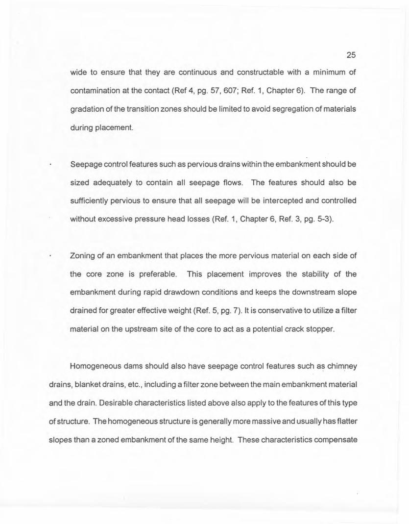
content to be permitted in the Specifications. Since the undrained strength is dependent
on dry density, it is desirable to obtain samples for testing by trimming cylindrical test
samples from a specimen compacted in a Proctor mold. Figure 1 shows the recommended
procedure.
Impervious foundation materials which are stiff and fissured may fail under drained
conditions (Le. shear-induced pore pressure equal to zero) even though they are fine
grained and subjected to short-term loading such as end-of-construction. This is because
the fissures permit rapid dissipation of the shear-induced pore pressures. Therefore, an
analysis using the drained strength may be more conservative and should be used if the
drained strength is lower than the undrained strength. See Sections 4-6.4.4 and 4-6.6.1.
Dr!J"OE!/J5/1!ItJ
);Im~x
/vtlit. -fer(/. Jd .
Obmia fesl sO/?7p/e 5from ?roc/or ~o/c/S4'/7?;o/e 5 4'/ wokrcOrJle/lrs ef'q-a/ ~"tJdry O'7d ~~/
waler conk!?/- I!"OJ1;}e
pe/'m/ffed /h S,Ae'CS"
W;I'I w;.,elCO,??PClCnO/7
Wale; CorJIe/J11U,
Figure I

45
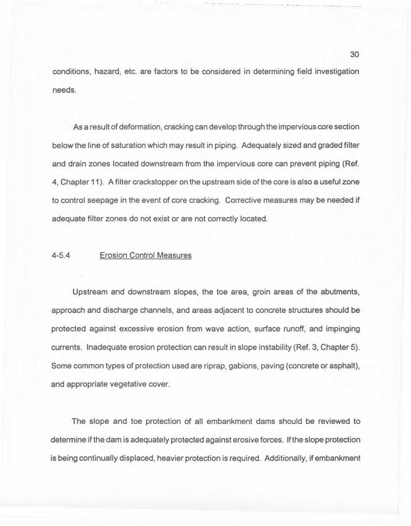
Figure 2 shows the stresses applied in the UU test and typical strength envelopes.
The confining pressure 0c is applied with the drainage line closed, followed by the
application of the axial stress AOa with the drainage line remaining closed. The axial stress
at failure is taken as the peak on the axial stress versus strain diagram or the axial stress
at an axial strain of 20 percent if no peak is present. Strength envelopes for saturated
samples are typically horizontal, whereas strength envelopes for partially saturated
samples are curved in the low confining pressure range. In cases where foundation or
embankment soils are unsaturated but will become saturated during construction, it is
advisable to saturate specimens prior to application of the axial stress.
Unconfined compression (UC) tests can be used to estimate the undrained shear
strength Su of saturated, fine-grained foundation materials. The undrained shear strength
of such foundation materials will generally be conservative for analysis of end-of
construction, because consolidation which occurs during construction will increase Su and
this increase is ignored when the UC results are used. Because the unconfined
compression test is far simpler to conduct than a UU test, it is commonly used in practice
to determine the undrained shear strength of saturated foundation materials .. Figure 3
shows the stresses applied to the sample and the shear strength envelope. As for the UU
test, the axial stress at failure (which is the unconfined compressive strength) is taken as
the peak on the axial stress versus strain diagram, or the axial stress at an axial strain of
20 percent if no peak is present.
l~~tc1c
O~[Yt~1 L\oa
6;, :::Oc. -I- L16ap .03;= ~
/V'ole.' As degree ofsQlclrtl!ron C7??rOqc/;es100 j/,.1 -/Q/!l/re e17velopea~~roacl;esIlor/eoah:1/
<1,;, I•.<16":1.---j6,:.t!f;..3
I-l

I~-I-.L<f-'=o"
1L164
0;;= .d6"C1f = ill03p==O
Fijure 3
46
Since the undrained shear strength is in general not constant with depth, unconfined
compression tests should be conducted on samples obtained from the range of depths in
the foundation materials which are likely to be involved in a potential failure. The results
of these tests should be used to develop a profile of undrained shear strength versus
depth in the foundation from which the available undrained shear strength along potential
failure surfaces at corresponding depths can be estimated.
The unconfined compressive strength will generally provide a conservative estimate
of undrained shear strength because of sample disturbance. Good undisturbed samples
are necessary and should be obtained from hand-carved block samples or thin-walled tube
samples having a minimum diameter of at least 2.5 inches.
The unconfined compression test should be limited to fine-grained soils classified
as CL, CH, ML, MH, or CL-ML.
Very stiff fine grained soils are often fissured and the unconfined compression test
may give misleadingly low unconsolidated, undrained strengths for these materials,
because premature failure will occur along fissures. Such materials are more appropri
ately tested in UU triaxial tests. More importantly, these materials may fail under drained
conditions. See Sections 4-6.4.4 and 4-6.6.1.

- -- --+ ---- ----- - - -- ~ -- - --- -- -- - -- -- -------
47
4-6.4.3 Consolidated-Undrained Shear Strength
(CU- or CD-type tests)
Consolidated undrained triaxial tests are referred to as CU-types or CD-types if
shear-induced pore pressures are measured in the test. Consolidated undrained triaxial
tests with pore pressure measurements have two primary uses in stability analyses: (1)
they furnish drained shear strength parameters, ¢' and c', for use in steady-state seepage
analyses or other loading conditions where shear-induced pore pressures can be taken
as zero (e.g. pervious zones in rapid drawdown or end of construction); and (2) they
furnish undrained shear strengths as functions of effective consolidation pressures for use
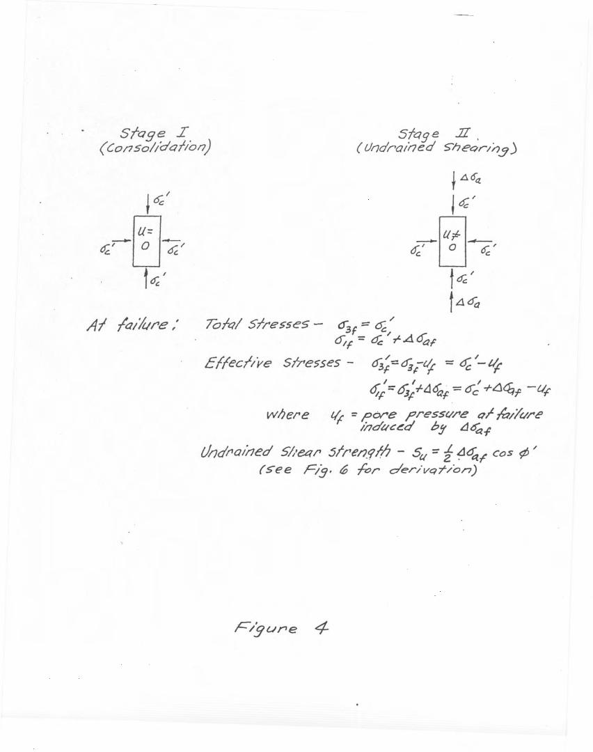
in rapid drawdown analyses and in earthquake analyses. Figure 4 shows the stresses
applied in CD tests. The confining pressure a~is applied with the drainage line open so
that the sample consolidates. The axial stress difference flOa is applied with the drainage
line closed which causes shear-induced pore pressures to develop inside the sample;
these are commonly measured with electronic pore pressure transducers inserted in the
sample drainage line. As in the UU and UC tests, the axial stress difference at failure is
taken as the peak on the axial stress difference versus axial strain diagram, or as the axial
stress difference at 20 percent strain if a peak is not present.
Sfage I(CO/1Sol/aQI/on)
Sfage .II.(Ur;dra/rJed 5'heQr//).3.)
t LlO~
J cf'
_M_6;;' LJ ~'t~'t4~
AI la/hre,' Tofql Slre>se5 - ~f:::: 0;;;O;f -= cf 7"Aoa,
Effecl/ve Sfresses - 6j;=cf3;-~ = q; /-tirI I /
01'::" Ojf+4<ff = Oc -htj~f -VF
wl;ere tit = pore ?ressC//'e Qr ~/I{/rC'//7dtlc~d bS' L1~.;
tJ/Jdrai/1ed 5//~/l 5lren.rlh - Su:: t ~~f" CoS ¢/(see Fig. 0 fOr derivq-r/on)
F/gure 4

48
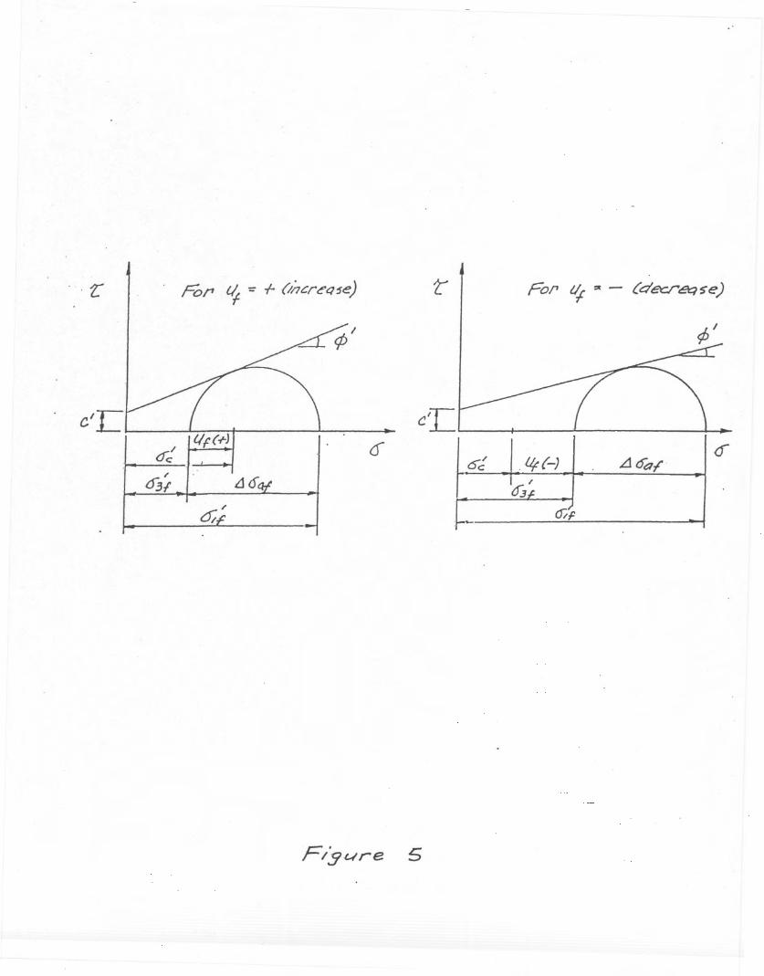
Figure 5 shows the~ffective stress Mohr-Coulomb failure envelope, from which the
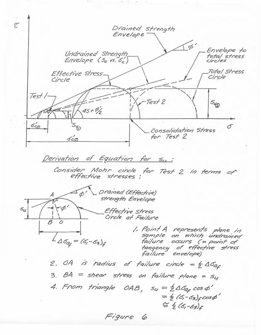
drained shear strength parameters cp' and c' can be determined. Figure 6 shows the
undrained strength envelope which is a plot of undrained shear strength as a function of
the consolidation pressure used in Stage I of the test.
As discussed in Section 4-6.6.2, rapid drawdown analyses should utilize shear
strengths obtained from a composite of the drained and undrained strength envelopes.
The normal stress used to select the shear strength from the composite envelope should
be the effective consolidation str~ss acting on the potential failure surface under steady
state seepage prior to drawdown (Le. the total normal stress minus the pore pressure
taken from a flow net drawn for the pool level before drawdown). Figure 7 shows the
composite envelope. In some cases, the drained and undrained envelopes may exhibit
slight curvature; however, they can typically approximated as linear to facilitate stability
calculations. This approximation does not cause significant error in the calculations.
Consolidation pressures used in the tests should encompass the range in effective
normal stresses which will act along potential failure surfaces prior to drawdown. Since
the undrained shear strength derived from the consolidated-undrained tests is highly
dependent on both compacted dry density and molding water content for embankment
materials, samples should be prepared as discussed for UU tests. Derivation of the
drained shear strength parameters from the consolidated-undrained tests depends on the
accurate measurement of shear-induced pore pressures, and the samples must be
'. t: For ~ ~ - (decr~S"e)
.Uf(-)
/·ac,
Dra;ned 5!rt'r'J9rhc/7ve/o?e
~ol?so~dalio;J51n>ssfor ?eST 2
.oer/VClf/o/1 0/ E~././aho/7 /'0, 50:Co~s-/der Mohr c//-c/e /'or ?eST 2 //7 Te/"~S or
ef'"/ecT/ve 5rre>5es:
D rt::)/;'ed cE"r/ed; ve)srreJ?9-Th E"17J/e/ar>e
crrecl/ve slress(/r.c/e qf ~//t//'e
;, ,Fb//) l,eq represe,,-;Ts ?/qne /'rJS'Qn?;:;/e ~n wh;c/J· vna'rQ/~eQ"fa/lure oCG:/rs (=pcvhr or7z:l'Jgenc!I or ef'"A>C?7ve srresS'fCl//L/re enve.lo'pe)
/s rC/d/~s or rq//u/"e' c/A=/e -= i ~~F
- sheQY' sr/'e$S 0/1 rq//vre ?/q~e = 5q
4. Fron? fr/e7/J.9/tt? OA8.) 54 = iL14r cos4S/-= i ('o;-o3)f'c<:J.s¢5/~i (0-05)1'
'2, 043. B4
Sfa!]e I
( CO/7.5o//dal/oa)
Sloge .7I
(Axial Compr8ssiol7)I ~6;l ac ~
c:J=a:~--0 ?c . c
f d; ~
tL16a
(b// srress-es q/'e e//ecl/ve srresse.v:/ /
03, == ~/ /
01 -= 0;; .,t. Ll6qf
·0
49
pressure saturated to ensure 100% saturation. Complete saturation can be verified by
applying an increment of all-around pressure with the drainage line to the sample closed,
measuring the pore pressure induced in the sample, and computing the B coefficient
(observed pore pressure divided by increment of all-around pressure). The B coefficient
should be at least 0.98 before conducting the axial loading stage of the test.
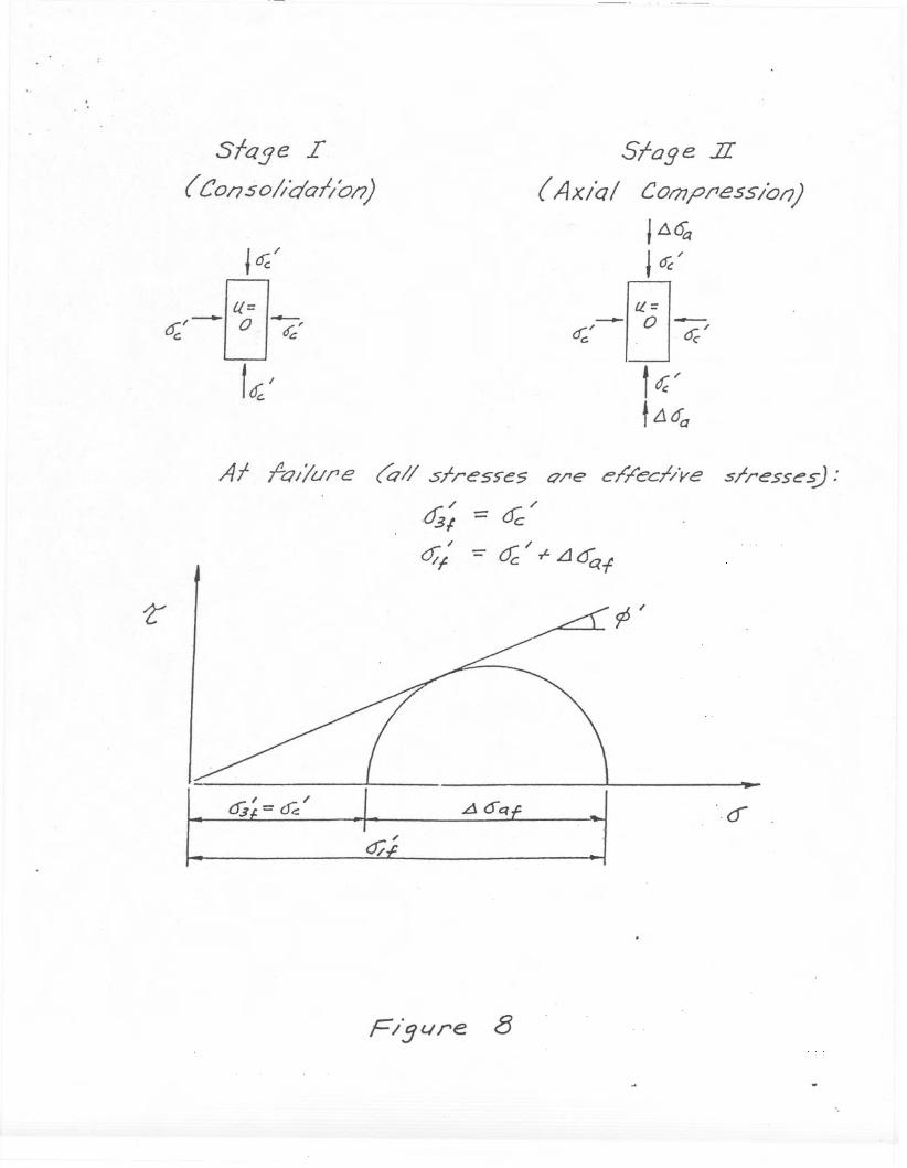
4-6.4.4 Consolidated-Drained Shear Strength (CD-type tests)
Consolidated drained triaxial test;; are used to obtain the drained shear strength
parameters, <P' and c'. Figure 8 shows the stresses applied in the test and the failure
envelope. The sample drainage line is open throughout the test so that the sample is
consolidated under the confining pressure o~ in the first stage of the test and so that the
shear-induced pore pressures are zero during the second stage of the test. The drained
strength envelope may exhibit slight curvature, but it may be approximated as linear with
sufficient accuracy.
The drained strength parameters <P' and c' are appropriate for use in analyses for
loading conditions in which the shear-induced pore pressures are zero. Examples would
be steady-state seepage for all embankment and foundation soils (except for those natural
soils such as overconsolidated clays or shales which may have been subject to past shear
deformations and for which the residual shear str:ength, Section 4-6.4.5, would be
appropriate), or end-of-construction or rapid drawc;lown loading conditions for pervious
50
soils or for stiff, fissured impervious soils with high secondary permeability due to the
fissures. The drained shear strength parameters from the consolidated-drained test can
be used in lieu of the parameters determined in the consolidated-undrained test with pore
pressure measurements to formulate the drained portion of the 'Composite Mohr-Coulomb
envelope for rapid drawdown analyses.
Since the drained shear strength parameters are a function largely of initial dry
density for a given soil, samples should be prepared as discussed in Section 4-B.4.2.
Confining pressures used in the test should encompass the range in effective normal
stresses which will act along potential failure surfaces.
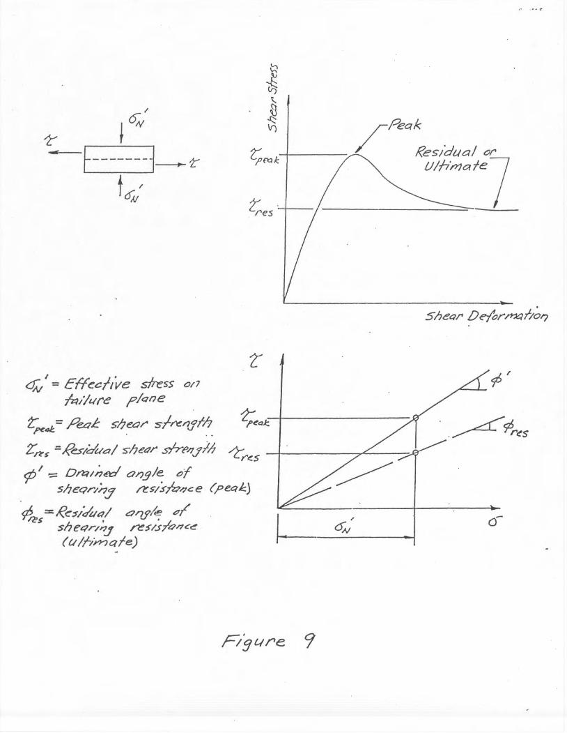
4-6.4.5 Residual Shear Strength
For foundations consisting of highly overconsolidated clays or shales, formations
which contain shear zones or faults, or colluvium and landslide deposits, deformations
along bedding planes, shear zones, faults, or landslide failure surfaces may have occurred
in the geologic past such that the maximum available shear str.ength alqng these
discontinuities is the residual shear strength. Under such conditions, direct shear or
rotation shear tests may be used to determine the residual strength. Figure 9 shows the
definition of the residual condition determined in a direct shear test and the residual angle
of shearing resistance <Pres.
I'
~
~
~-------1 ~~t~/
l;es'
<::0 I = Effe~l/ve s/ress 0/7-fi:l//L/re f'/Qne
t"~4I:.= Peae sl;~o~S';'~'1.f/"!. -2;~Qk
Z'~$=Res/dual slJec;r sfr{>/11!/; ~~ - LT'<.SI .¢ '== Dmnuxl angle "I
sheQr/n:J ~ 5/S/4"/1C e (pee"::.)
¢/? = R~~/dut:l/ O'lf'le p/,$ shet:1r/~ ~5/5/QrtC~ I(vII-in-? Clfe) f--- ~

51
Samples should be oriented in the direct shear device such that shearing occurs
parallel to the discontinuity so that the residual strength is measured; however, this is not
always practical. Since the residual strength depends primarily on the mineralogy of the
material along the discontinuity remolded samples may be used in dir~ct shear or rotation
shear devices. Remolded samples should be consolidated to normal stresses
corresponding to the range in effective normal stresses which will act on the discontinuity
in the problem to be analyzed. Because very large shear deformation may be required to
establish the residual condition, there is sometimes a tendency in practice to stop the tests
before sufficient deformation has occurred. This results in an overestimate, and hence an
unconservative estimate, of <Pres. Thus, empirical correlations such as given in {Reference)
should always be considered in determining the appropriate value of <Pres.
The direct shear test described in Figure 9 can also be used to determine the
drained shear strength parameters <P' and c' if the peak shear strength is plotted versus
the effective normal stress. The results are comparable to those obtained from CD or CD
triaxial tests.
4-6.5 Note on Types of Stress Analyses and Terminoloqy
In the past it was common to refer to two types of stability analyses: the "total stress",
and the "effective stress" analyses. This terminology gives the erroneous impression that
in the use of the so-called "total stress" analysis, one would select undrained shear
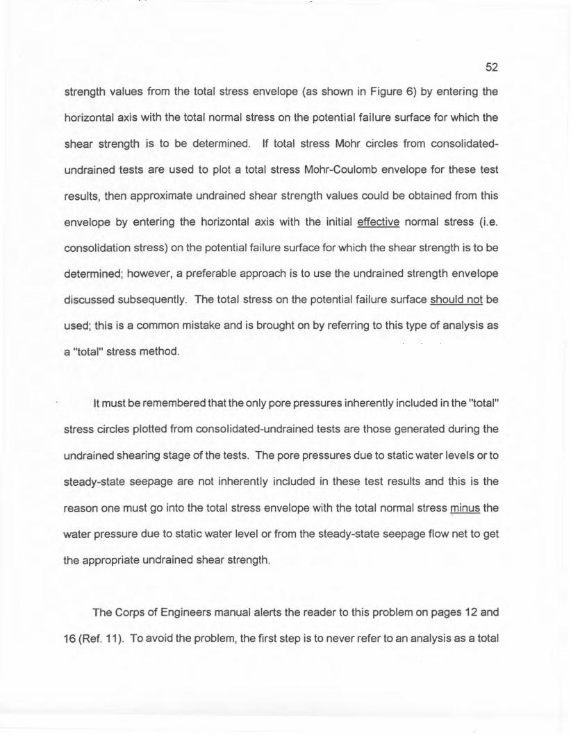
52
strength values from the total stress envelope (as shown in Figure 6) by entering the
horizontal axis with the total normal stress on the potential failure surface for which the
shear strength is to be determined. If total stress Mohr circles from consolidated
undrained tests are used to plot a total stress Mohr-Coulomb envelope for these test
results, then approximate undrained shear strength values could be obtained from this
envelope by entering the horizontal axis with the initial effective normal stress (Le.
consolidation stress) on the potential failure surface for which the shear strength is to be
determined; however, a preferable approach is to use the undrained strBngth envelope
discussed subsequently. The total stress on the potential failure surface should not be
used; this is a common mistake and is brought on by referring to this type of analysis as
a "total" stress method.
It must be remembered that the only pore pressures inherBntly included in the "total"
stress circles plotted from consolidated-undrained tests are those generated during the
undrained shearing stage of the tests. The pore pressures due to static water levels or to
steady-state seepage are not inherently included in thBse test results and this is the
reason one must go into the total stress envelope with the total normal stress minus the
water pressure due to static water level or from the steady-state seepage flow nBt to get
the appropriate undrained shear strength.
The Corps of Engineers manual alerts the reader to this problem on pages 12 and
16 (Ref. 11). To avoid the problem, the first step is to never refer to an analysis as a total

53
stress analysis, which in itself is a form of enticing a reader to make the wrong decision.
Instead, the terminology "undrained strength analysis" should be used. The second step
is to abandon the total stress Mohr-Coulomb envelope in preference for an undrained
strenQth envelope as shown in Figure 6. The undrained strength envelope is a plot of the
undrained shear strength developed on the failure plane (determined from consolidated
undrained tests) versus initial effective consolidation pressure on that same plane. Then,
in an analysis in which the undrained shear strength is required, it is very straight forward
to obtain the correct strength by entering the diagram at the initial "effective" consolidation
stress on the potential failure surface in question.
While it is not incorrect technically to refer to an analysis utilizing the drained shear
strength as an "effective" stress analysis, it is recommended that such analyses be
referred to as "drained" analyses, or analyses in terms of "drained" shear strength. This
notation will help to avoid the temptation to refer to the undrained strength analyses as
total stress analyses. Theoretically, it is possible to carry out analyses in which failure is
assumed to occur under undrained conditions (i.e. shear-induced pore pressures cannot
dissipate and are therefore not zero). using effective stresses at failure along with
"effective" stress shear strength parameters determined from CD or CO type triaxial tests.
However, to do an analysis in this manner requires estimation of pore pressures caused
by changes in all-around stress (functions of Skempton's B-coefficient), and shear-induced
pore pressures (functions of Skempton's A-coefficient), as well as static and seepage pore
pressures. Because of uncertainties involved in estimating field values of Skempton's A

54
and B coefficients, this type of analysis is not recommended. The undrained str-ength
analysis should be used instead.
·4-6.6 Loadina Conditions for Analysis and Selection of Shear Strenath Values
As outlined in Section 4-6.3, an embankment may be subjected to several loading
conditions during its life, ranging from construction to full pool operation. The loading
conditions for which an embankment must be analyzed and the shear strength values
appropriate for use in the analyses are presented in detail in the following paragraphs.
4-6.6.1 End of Construction Loadina Condition
At the end of construction, an embankment dam may still be undergoing internal
consolidation under its own weight. For homogeneous dams or for zones in dams
constructed of impervious materials, pore water pressures will be built up during
construction if the rate of consolidation of the embankment materials is slow compared to
the rate of fill placement. Low permeability, natural foundation layers which are too thick
to consolidate a significant amount during construction will also develop excess pore
pressures caused by the weight of the embankment.
When such conditions are present, applicable shear strength values are determined
from UU tests. For embankment materials, tests should be performed on iaboratory

55
samples compacted to specified dry densities at water contents within the range of
compaction water contents permitted in the specifications, as discussed in Section 4
6.4.2. Confining pressures used in the tests should encompass the range in total normal
stresses which would be present along potential failure surfaces in the dam.
For natural foundation soils, shear strength values can be determined fmm UU tests
or unconfined compression tests on undisturbed samples, as discussed in Section 4-6.4.2.
Shear strengths so determined will usually be conservative provided the foundation soils
are normally consolidated or slightly overconsolidated such that embankment loading
causes the maximum previous consolidation stress to be exceeded, because some
consolidation and gain in strength will occur during construction. Evaluation of the time
rate of consolidation and resulting gain in strength may show that staged construction
would result in a significant increase in foundation strengths during construction and
permit a more economical embankment design.
Overconsolidated natural foundation soils which are stiff and fissured should be
tested in UU tests to determine end-of-construction shear strength because ~nconfined
compression tests will give misleadingly low strengths for fissured materials. This is
because premature failure will occur along the fissures under the condition of zero
confining pressure. More importantly, these materials may fail under -drained conditions
(shear induced pore pressures are zero), even though the intact material between fissures
may be of low permeability. The drained shear strength can be determined from CD or CD

---------- ... - ---- .... ---- --._--
56
type tests and may be less than the strength determined from UU tests. In this case it will
be more conservative to use the drained shear strength as the end-of-construction
strength for such materials. See Section 4-6.4.2.
For pervious zones in the embankment where drainage can occur rapidly, drained
shear strengths should be used in the analysis. These zones would include drains, filters,
rock fill shells, and gravel shells.
The analysis that applies for this loading condition is the undrained strength analysis
(or the drained strength analysis for stiff fissured materials or pervious zones as discussed
in the preceding paragraphs). Because of the difficulty in estimating pore pressures within
the embankment during this stage of loading, an effective stress analysis is not
recommended. (See Section 4-6.5). An effective stress analysis may, however, be
conducted using pore pressure responses in previously constructed dams that used
materials, construction methods, and -construction schedules similar to those for the
proposed dam. In this type of analysis, shear strength parameters determined from CD
or CD tests are used and effective stresses are calculated using the pore pressures
observed in the similar previously constructed dams.
If there are any serious questions about stability during or at the end of construction,
the only positive method to determine the stability is to install pi,ezometers and evaluate
the stability during construction using an effective stress analysis. The results of such an

57
analysis may require alteration of the construction schedule or other methods to ensure
stability.
4-6.6.2 Rapid Drawdown LoadinQ Condition
In the rapid drawdown loading condition the embankment has been subjected to a
prolonged high pool during which time a steady seepage condition has been established
through the embankment. The soil in the embankment below the phreatic surface is in a
completely saturated state and is fully consolidated under the weight of the overlying
material. If subsequently the reservoir pool is drawn down faster than pore water can
escape, excess pore water pressures and unbalanced seepage forces develop.
Consequently, the factor of safety following a reservoir drawdown is reduced (Ref. 16, p.
370). This is usually the critical condition for design of the upstream portion of the
embankment. Analyses for the rapid drawdown condition are based on the conservative
assumptions that (1) pore pressure dissipation does not occur during drawdown, and (2)
the reservoir water surface is lowered instantaneously from maximum pool, spillway crest,
or top of gates to the minimum pool (Ref. 11, pg. 16). For core materials of low permeabil
ity the drawdown may take place during a period of days, or even weeks, and still be
termed rapid or "sudden". The assumption of no drainage at all in the core material during
drawdown is frequently a close approximation of actual conditions and is conservative
(Ref. 40, pg. 538).

58
For embankments composed of impervious materials, the shear strength available
to resist failure after drawdown is governed by the effective consolidation stresses along
the potential failure surface for steady state seepage prior to drawdown. The shear
strengths to be used should be the smaller of the drained or undrained strengths taken
from the combined envelopes shown and explained in Section 4-6.4.3 {Ref. 11, pg. 16).
This is conservative and ignores the cases where the undrained shear strengths are
higher than the drained shear strengths because of negative pore pressures generated
during shear.
Shear strengths of free-draining shell materials, defined as those in which drainage
of pore water can proceed concurrently with lowering of the pool or with only a minor time
lag, should be taken from the drained strength envelope (Ref. 11, pg. 16).
As discussed by Lowe and Karafiath, it has been found that the cons01idated
undrained shear strength of a clay soil depends on the principle stress ratio at the time of
consolidation (Ref. 40, page 539). Principle stress ratios along a potential failure surface
can be estimated for the high reservoir level immediately before drawdown. Anisotropi
cally consolidated undrained triaxial tests can then be conducted at these principle stress
ratios to determine the undrained shear strength for use in the after drawdown stability
analyses. The reader is referred to Reference 40 for a detailed discussion of this method.
59
Duncan, et al. (Ref. 41) have developed a procedure for estimating the undrained
shear strength resulting from anisotropic consolidation by interpolation from the results of
isotropically consolidated tests. Because anisotropically consolidated tests are more
difficult and expensive to perform than isotropically consolidated tests, the interpolation
procedure makes the use of undrained shear strength resulting from anisotropic
consolidation easier to use in practice, if it is desired to take into account the effects of
anisotropic consolidation. The reader is referred to Reference 41 for a detailed discussion
of the method.
Where the sudden drawdown loading condition controls the design of the upstream
slope, and where the rapid drawdown assumption appears to be excessively conservative,
consideration of possible drawdown rates along with permeabilities of relatively
incompressible embankment materials can be used to construct flow nets. The flow nets
can be used to determine pore pressures from which effective consolidation stresses are
calculated to determine shear strengths. An approximate procedure for this type of
analysis is given in Appendix III of Reference 11.
4-6.6.3 Steady SeepaQe LoadinQ Condition
Steady seepage develops after a reservoir pool has been maintained at a particular
elevation (e.g., maximum storage pool) for a sufficient length of time to establish a steady
line of saturation through the embankment. The seepage forces which develop in the
60
steady state condition act in a downstream direction, and therefore the condition of steady
seepage through an embankment may be critical for downstream slope stability (Ref. 11,
pg. 19). The upstream slope need not be analyzed for this condition if the upstream slope
was designed for rapid drawdown. The seepage forces can be conservatively estimated
by assuming a horizontal phreatic line from the elevation of the pool to the downstream
limit of the impervious zone. However, high abutment groundwater tables may cause the
phreatic surface to be higher in the vicinity of the abutments. In homogeneous impervious
embankments, orwhen the assumption of a horizontal phreatic line in the impervious zone
is overly conservative, the line of seepage can be estimated by various methods (Ref. 18,
Ref. 19, Ref. 5). If sufficient instrumentation is available for an existing embankment dam,
piezometer levels in both the embankment and foundation can be reviewed and phreatic
surfaces can be developed accordingly.
The pore water pressures which exist within an embankment at any given time are
the result of (1) static water levels or gravity seepage flow, and (2) changes in pore volume
produced by changes in all-around stress or shear stress. In analysis of the steady
seepage loading condition, pore water pressures due to changes in all-aroundstress are
assumed to be zero (i.e. consolidation of the impervious embankment zones is assumed
to be complete) and it is also likely that shear-induced pore water pressures in impervious
zones are zero. This is because the steady seepage condition is assumed to develop
slowly enough for the second category of pore water pressures to have dissipated. Thus

61
the only pore water pressures assumed to be present in the embankment are those due
to static water levels or gravity seepage flow.
Under these assumptions the shear strength available would be the drained shear
strength, whereas if shear-induced pore pressures were not assumed to be zero, the
undrained shear strengths would be used. For design purposes, however, the Corps of
Engineers generally use the shear strength for impervious soils from a composite strength
envelope midway between the drained and undrained envelopes, for effective normal
stresses in the range where the drained strength is greater than the undrained strength
(Ref. 11). This approach allows for the condition where positive shear-induced pore
pressures in impervious embankment zones may not be completely dissipated and is
conservative. For the range in effective normal stresses on a potential failure surface
where the drained shear strength is less than the undrained shear strength, the drained
shear strength is used. Figure 10 shows the composite design shear strength envelope.
It is emphasized that the normal stress to be used is the effective normal stress on the
potential failure surface. The shear strength of freely draining cohesion less soils should
be taken from the drained strength envelope determined from CD or CD tests as discussed
in Sections 4-6.4.3 and 4-6.4.4.
In the case of an old existing dam, where the steady seepage condition has been
present for a long period of time under a more or less static reservoir level, it is likely that
shear-induced pore pressures have completely dissipated. Use of the design envelope
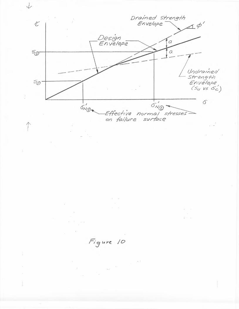
~ii
,Des-ig??E I? ve /Ot:J2r
Dra/ned 5"l-rer7gfh
Envelope --y¢/
62
shown in Figure 10, midway between the drained and undrained envelopes is probably
overly conservative for compacted embankments. Thus, the drained shear strength
envelope should be used for evaluating stability of dams in this category.
In the case where a steady seepage condition exists in an embankment, an
additional horizontal thrust in the downstream direction may be imposed by a surcharge
pool up to the probable maximum pool elevation. The surcharge pool should be
considered as a temporary condition causing no saturation of impervious materials above
the steady seepage phreatic line established under normal reservoir conditions. The
shear strengths to be used in the stability analyses should be the same as used for the
steady seepage condition with maximum storage pool.
4-6.6.4 Partial Pool Loadinq Conditions
Analyses of the upstream slope for intermediate reservoir stages should be
conducted assuming that a steady seepage condition has developed at the intermediate
stages. The shear strengths to be used should be the same as for the steady seepage
condition for the downstream slope, discussed in Section 4-6.6.3. Stability analyses
should be performed for several pool elevations and the factors of safety plotted as a
function of reservoir level to determine the minimum factor of safety.
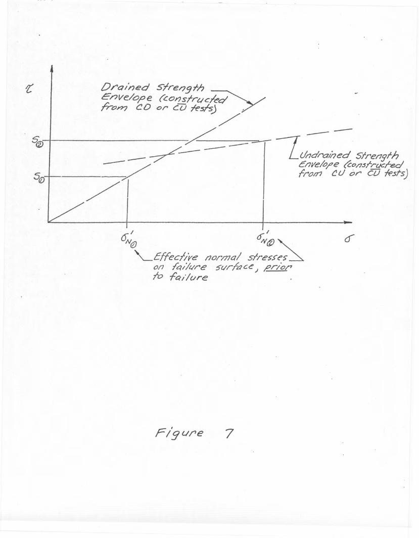
Dro/ned Slre/l.9fh
Enve/o'p€ (c.orJsfrtlc~ . .//,ro~ CD or CU fesh-j ..... 7/ --. ~ --~--r--/ -- -- LUadroloed 5frer/gfh-- -- --:;;:::r- c/Jve/o/,e (CO/7srrC/Cl-ed
-/ frol71 ~ U or" cu -ffsrs)/1I . I
ON@ o:v ct) """-.EffechVe l70rmal slres.>C's ~0/1 feu/tire 5t1r/ac~) e.rio/'Iv -fa/lure

63
Where pore water pressures developed during construction are not dissipated
before a partial pool condition can develop, the reduced effective normal stress along a
potential failure surface must be accounted for in the analysis.
4-6.7 Factors of Safety
The factor of safety provides a margin of safety to guard against ultimate failure, to
avoid unacceptable deformations, to reduce the risk of progressive failure, and to cover
uncertainties associated with the measurement of soil properties, the loading, or the
analysis used (Ref. 22, pg. 48). In selecting a minimum acceptable factor of safety an
evaluation should be made on both the degree of conservatism with which assumptions
were made in choosing soil strength parameters, pore water pressures, and loading
conditions; the consequences and the influence of the method of analysis which is used
(Ref. 16, pp. 369-371). The latter concerns the method of calculation in which side earth
forces are considered and how assumptions of directions of side earth forces affect
stability analysis results. It also concerns assumptions relative to the dissipation of shear
induced pore pressures and whether anisotropic consolidation is accounted for in the
determination of undrained shear strength.
An estimate of the factor of safety can be obtained by examining conditions of
equilibrium when incipient failure is postulated, and comparing the shear stress necessary
to maintain equilibrium with the available shear strength of the soil (Ref. 23).

64
Therefore, the slope stability analysis of embankments requires measurements of
the shear strength and computation of the shear stress. Appropriate minimum values of
factors of safety to be required in the stability analysis of a slope depend on the
measurement of shear strength, likelihood of the assumed loading, consequences of
failure, and assumptions in the method of analysis. Factors influencing the selection of
minimum factors of safety include:
Reliability of laboratory shear strength testing results
Embankment height
Storage capacity
Thoroughness of investigations
Construction quality, construction control of embankment fills
Judgment based on past experience and knowledge of precedents
Design conditions being analyzed
Predictions of pore water pressures used in effective stress analyses
Minimum factors of safety generally required by FERC are listed in Table 1. The
minimum Factors of Safety given in Table 1 are to be used in conjunction with analyses
using peak shear strengths. If certain wedges involving foundation shales are analyzed
using residual or near residual strength, then lower Factors of Safety than those given in
Table 1 for the static cases are generally acceptable. The specific values being
dependent on the percentage of the failure surface assumed to be at the residual strength.
----~-.----.--- -._- --- -." - --~.-- ------0. _. • "'0_ -- .. - -- -- - -- - - -- -- ----- ---.-- - ---. - .. -

65
Final accepted factors of safety will also depend upon the degree of confidence in the
engineering data available. In the final analysis, the consequences of a failure with
respect to human life, property damage, and impairment of project functions are important
considerations in establishing factors of safety for specific investigations.
4-6.8 Static Stability Analyses
Various analytical methods for evaluating the static stability of an embankment dam
exist. The method utilized in the licensee's analysis should be consistent with the
anticipated mode of failure, dam cross section, and soil test data.
Many methods of stability analyses exist that use the same general approach of
employing the "limit equilibrium method" of slope stability analysis. In this type of
approach an estimate of factor of safety can be obtained by examining the conditions of
equilibrium when incipient failure is postulated, and comparing the shear stress necessary
to maintain equilibrium with the available shear strength of the soil. The factor of safety
(F.S.) is thus defined as the ratio of the shear strength available (s) on the potential failure
surface to the shear stress mobilized 't' along the failure surface in order to maintain
equilibrium(Ref. 24). This can be expressed as
F.S. = ..§...
't'(1 )

Table 1
MinimumSlopeShear
Loading
Factor ofto beStrengthCondition
SafetyAnalyzedEnvelope
End of construction
1.3upstream andcondition
downstream
Sudden drawdown from
>1.1 *upstreammaximum pool
Sudden drawdown from
1.2*upstreamspillway crest or top of oates
Steady seepage with
1.5upstream andmaximum storaoe pool
downstream
Steady seepage with
1.4downstreamsurcharoe pool
Earthquake (for steady
> 1.0upstream and
seepage conditions with
downstream
seismic loading using a pseudo static lateralforce coefficient)
A state of limiting equilibrium exists when the shear strength mobilized is expressed as:
66
1"m= 1.i§}
F.S.(2)
F.S. is the factor of safety with respect to shear failure and 1/F.S. is a measure of the
degree of mobilization of the shear strength. It may be shown that the definition of F.S.
given by equation (1) is equivalent to the one used in the Ordinary Method of Slices, where
the factor of safety is defined as the ratio of the resisting moment to the driving moment
(Ref. 25, page 784).

67
The drained shear strength of a soil is expressed by the following expression:
s = c' + o~ tan ¢'
in which c' and ¢' are the cohesion intercept and slope of the Mohr-Coulomb diagram and
o~ represents the effective normal stress on the failure surface.
The undrained shear strength is given by the undrained shear strength envelope
(Figure 6) which is a plot of Su as a function of o~,where o~ is the effective consolidation
stress on the failure surface, prior to the undrained failure. Thus, to determine the shear
strength along a potential failure surface, the effective normal stress or consolidation
stress on the failure surface must be known.
In analyzing both force and moment conditions of equilibrium it becomes apparent
that the problem of determining the distribution of the effective normal stress or
consolidation stress on the failure surface is statically indeterminate, that is, there are
more unknowns than there are equations of equilibrium (Ref. 25). An approach to this
situation is to make assumptions to reduce the number of unknowns in order that the
problem is statically determinate, such as is done in the "limit equilibrium"· analysis
procedure. Different procedures use different assumptions. Some methods do not satisfy
all conditions of moment and force equilibrium. Table 2 shows equilibrium conditions
satisfied by various methods of analysis.

68
Studies have been performed to examine the accuracy of the equilibrium methods
of slope stability analysis (Ref. 25, pp. 783-791, Ref. 26, pp.475-498). Except for the
ordinary Method of Slices, which gives the lowest and hence most conservative values for
the F.S., and the differences are probably within the range of uncertainty in the shear
strength parameters.
Table 2
Equilibrium Conditions Satisfied
OverallIndividualSlice
VerticalHorizontal
Procedure
MomentMomentForceForce
Ordinary Method of Slices
YesNoNoNo
Bishop's Modified Method
YesNoYesNo
Corps of Engineers
NoNoYesYesModified Swedish Method
Janbu's Generalized
YesYesYesYesProcedure of Slices
Spencer's
YesYesYesYesProcedure
Morgenstern and Price
YesYesYesYes
In Appendix 4C a step by step illustration is given for Stability Analyses for Steady ,
State Seepage and Rapid Orawdown using the Corps of Engineers Modified Swedish
Method. Actual calculations from a high central core, rockfill dam are shown in Appendix
40.

4-6.9 Earthquake
£Vlt:7#J::; +YT'J-. P b7-8toJ-? i,; ~'1),j<"y<:j <::>'15 •••...
1/-<7 J;<:~};,"t'~ d"",;re.~ "Y7,~f- ~ ct;.,.~ .,;-~.
~}pt-
69
Evaluation of seismic effects for embankments located in areas of low seismicity
(0.10 or less) may be accomplished using the seismic coefficient in the pseudostatic
method of analysis. Seismic coefficients at least as large as shown in figures 6, 6a, 6b,
and 6c of Reference 11 shall be employed as applicable (Ref. 11, change 1, dated 17
February 1982). The pseudostatic method assumes that the earthquake causes additional
horizontal forces in the direction of potential failure. This investigation need only be
applied to those critical failure surfaces found in analyzing steady state seepage. An
analysis of earthquake loading is never necessary in conjunction with sudden drawdown
stability analysis for nearly all dams. However, if earthquake loading is possible during
reservoir drawdown associated with a pumped storage project where frequency of
drawdown occurs on a daily cycle, earthquake effects during sudden drawdown should be
investigated. The selection of shear strengths to be used in the analysis are discussed
in Section 4-7.
For embankments located in areas of strong seismicity, a dynamic analysis of
embankment stability should be performed based on present state-of-the-art procedures.
Refer to Corps of Engineers ER 1110-2-1806, "EarthquakeDesign and Analysis for Corps
of Engineers Dams," for the earthquake loading to be used in dynamic analyses and for
guidance in performing seismic evaluations.
70
In general, an embankment dam should be capable of retaining the reservoir under
conditions induced by the maximum credible earthquake where failure would cause loss
of life. The following investigations should be accomplished for all proposed and existing
embankments, with the exception that existing confirmed "low" hazard potential dams may
be exempted from these investigations.
A seismic stability investigation using a dynamic analysis for proposed and existing
dams located in Seismic Zones 3 and 4 of Reference 33.
An evaluation of the liquefaction potential for all dams that have or will have
liquefiable materials either in the embankment or foundation.
A geological and seismological review of existing dams in Seismic Zones 2, 3, and
4 of Reference 33, to locate faults and ascertain the seismic history of the region
around the dam and reservoir.
A seismic stability investigation of existing dams by dynamic analyses, regardless
of the seismic zone in which the dam is located where capable faults or recent
earthquake epicenters are discovered within a distance where an earthquake could
cause significant structural damage.

71
4-7 Seismic Stability Evaluation
4-7.1 General Approach
Various methods of analyses are available for evaluating the seismic stability of an
earth dam. These may be classified as:
Pseudostatic methods
Deformation analyses for non liquefiable soils
Evaluation of potentially liquefiable soils
Regardless of the method of analysis, the final evaluation of the seismic safety of
the embankment should be based on all pertinent factors involved in the investigation and
not solely on the numerical results of the analysis (Ref. 21). References presented in the
Corps of Engineers ER 1110-2-1806 can be used in determining the scope of analysis
required for properly assessing the seismic stability of an embankment dam.
Analyses for earthquake loading should begin with simplified procedures and
proceed to more rigorous methods of analyses as a particular situation may
warrant. Projects with well compacted embankments and dense foundation soils
located in Seismic Zones 1 or 2, (Ref. 33), and all confirmed low hazard potential

72
projects, may be evaluated by the pseudostatic method using the seismic coefficient
assigned to the seismic zone in which the project is located.
In areas of severe and/or frequent seismic loading such as in seismic Zones 3 and
4 or where foundation liquefaction potential exists, more rigorous dynamic methods
of analyses may be necessary (Ref, 33). Site specific seismic evaluations will be
performed for all projects not covered in the paragraph above. These studies will
identify earthquake source areas, the maximum credible earthquake, and the
distance from the site of each relevant source area. Potential for fault rupture in the
dam foundation and in the reservoir will be assessed. The modes of failure that
need to be investigated and the appropriate methodology are described in the
following subsections.
4-7.2 Modes of Failure:
a. Loss of Stability
The dam becomes unstable as a result of loss in strength in the dam or foundation
when they are composed of loose constructive sands. - Liquefaction Slide - typical
examples: Lower San Fernando Dam and Ft. Peck Dam. In the case that liquefaction may
be triggered by earthquake motions, the post earthquake stability must be assessed.
73
b. Excessive Deformations
The dam remains stable during and after the earthquake; however, deformations
can accumulate during earthquake shaking. The accumulated deformation needs to be
estimated and evaluated with respect to its effects on the likelihood of an uncontrolled
release of water from the reservoir. These deformations should be estimated by either the
Newmark or Seed-Makdisi methods, for all dams in Seismic Zones 3 and 4.
c. Other Mechanisms
Overtopping due to seiches
Movements along a fault passing under the dam
Landslides in abutments causing direct damage to the dam or due to a wave in
reservoir caused by an earthquake induced slide.
4-7.3 Methods of Analyses
a. Pseudostatic Analysis Procedures
For many years the standard method of evaluating the safety of embankment dams
against sliding during earthquakes has been the pseudostatic method of analysis. This

74
approach should not be used for those cases where potentially liquefiable materials are
estimated to be triggering along the potential failure surface.
In general, therefore, earthquake analyses using the seismic coefficient method
may be performed only for structures proposed or existing in Seismic Zones 1 and 2.
Seismic coefficients at least as large as shown in the Corps of Engineer ER 1110-2-1806,
should be employed in the analysis (Ref. 33). In the analyses conducted with the seismic
coefficient, the undrained shear strength should be used consistent with initial effective
normal consolidation pressures determined from the conditions for steady state seepage
at normal pool. The Factor of Safety computed using the seismic coefficient in a pseudo
static analysis with the appropriate undrained strength should be at least 1.0, as indicated
in Table 1.
b. Deformation Analysis - Non liquefiable Soils
For those dams located in Seismic Zones 3 and 4 and for which neither the
embankment or the foundations are composed of potentially liquefiable soils, the dynamic
deformations should be calculated by either the Newmark Method (Ref. ) or the Seed
Makdisi Method (Ref. ). For both methods, one common element or step in the
calculation of the dynamic inelastic displacements, is the calculation of the yield
acceleration of the sliding mass being evaluated. The yield acceleration is the minimum
value of a pseudo static acceleration times the mass of the failure wedge which will just

75
bring the potential failure mass to a Factorof Safety of 1.0 (i.e. the inertia force required
to fully develop the undrained strength on the potential failure surface). In the evaluation
of the yield acceleration the consolidation stresses on potential failure surfaces should be
determined for the steady state seepage case at normal high reservoir. The undrained
shear strengths selected should be consistent with these consolidation pressures along
the potential failure surface.
The calculations of yield accelerations for various cases are illustrated in Appendix£
4-i>. The deformations calculated for potential failure masses by the Newmark or Seed
Makdisi Methods should normally not exceed 2 feet and should never be greater than
about one-half of the filter thickness. Some investigators have made deformation
calculations according to the methods described herein and have taken the free board as
the allowable permissible deformation. Although keeping the calculated displacement less
than the free board is a necessary condition, it is not a sufficient condition to assure safe
performance of the dam. Loss of uncontrollable seepage and erosion is a possibility due
to cracking at displacements smaller than the free board. The allowable inelastic
displacements calculated by this method are about two feet and should not be more than
one-half the thickness of the filter zones in any case.
Calculations of inelastic deformations utilizing the Newmark Method are given ine
Appendix 4-f.
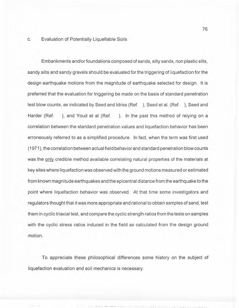
76
c. Evaluation of Potentially Liquefiable Soils
Embankments and/or foundations composed of sands, silty sands, non plastic silts,
sandy silts and sandy gravels should be evaluated for the triggering of liquefaction for the
design earthquake motions from the magnitude of earthquake selected for design. It is
preferred that the evaluation for triggering be made on the basis of standard penetration
test blow counts, as indicated by Seed and Idriss (Ref. ), Seed et al. (Ref. ), Seed and
Harder (Ref. ), and Youd et al (Ref. ). In the past this method of relying on a
correlation between the standard penetration values and liquefaction behavior has been
erroneously referred to as a simplified procedure. In fact, when the term was first used
(1971), the correlation between actual field behavior and standard penetration blow counts
was the only credible method available correlating natural properties of the materials at
key sites where liquefaction was observed with the ground motions measured or estimated
from known magnitude earthquakes and the epicentral distance from the earthquake to the
point where liquefaction behavior was observed. At that time some investigators and
regulators thought that it was more appropriate and rational to obtain samples of sand, test
them in cyclic triaxial test, and compare the cyclic strength ratios from the tests on samples
with the cyclic stress ratios induced in the field as calculated from the design ground
motion.
To appreciate these philosophical differences some history on the subject of
liquefaction evaluation and soil mechanics is necessary .
• - - --- -- --- -.--.-- _n ••• ,. •••••• _._ ••• _ • u_u

77
Soil Mechanics has given Civil Engineers the tools for calculating the Factors of
Safety for stability problems and the means for estimating deformations, seepage and
porepressures in terms of the shear strength, compressibility, and permeability properties
of the soil materials. The classical approach to many design problems in geotechnical
engineering has consisted of:
1) obtaining representative samples
2) conducting the appropriate laboratory tests on the representative sample to
obtain the strength, compressibility or permeability
3) analyzing the problem within the framework of soil mechanics and rock
mechanics, utilizing the material properties obtained from samples in order
to reach a conclusion helpful for design or evaluation.
Although this classical approach has worked where "representative" samples of the
mass can be obtained and tested, this approach is not appropriate for applied problems
in sands. The classical approach is not directly applicable for these cases because
"representative" samples can not be reliably obtained without changing the density. For
these cases the use of precedent in the form of key case histories is the most direct
approach and soil mechanics is used to back-calculate strength, stiffness, and
permeabilities from the actual field performance of soils. This approach is often labeled
as an "empirical" method and wrongfully relegated to a second class status by those who

78
favor the classical approach but fail to perceive that the "representative" sampling problem
cannot be overcome.
The evaluation of liquefaction problems in the design or evaluation of Civil
Engineering structures founded on sands sometimes results in a confrontation of the two
approaches. The confrontation usually develops because one group of engineers believes
that "representative" samples of sands can be obtained and tested to yield meaningful
strength properties. Another group of engineers associated with the same project may
favor an engineering decision based upon correlations between penetration tests and
back-calculated strengths from key case histories or precedents. In Appendix 4-? two
case histories are reviewed which illustrate the nature of the conflict; one concerns the
design of a nuclear plant on sands, the other involves the evaluation of an existing dam
in an area with earthquake potential.
Experience indicates that this philosophical choice occurs with great regularity on
many civil engineering problems. The use of precedents in geotechnical problems
however assumes a greater importance than in other areas of civil engineering because
many of the idealized assumptions which are made in the classical approach may not be
realized in practice. Therefore the "classical" approach should not be used, no matter how
logical it may seem, unless it is substantiated by field behavior.
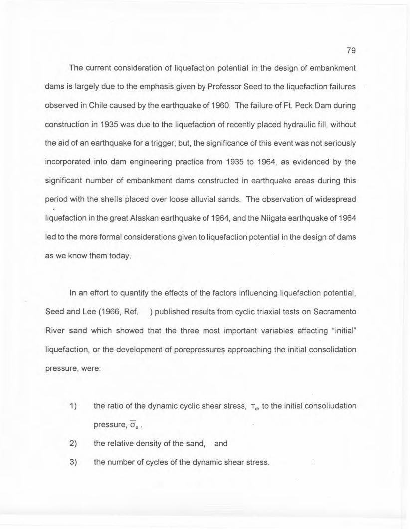
79
The current consideration of liquefaction potential in the design of embankment
dams is largely due to the emphasis given by Professor Seed to the liquefaction failures
observed in Chile caused by the earthquake of 1960. The failure of Ft. Peck Dam during
construction .in 1935 was due to the liquefaction of recently placed hydraulic fill, without
the aid of an earthquake for a trigger; but, the significance of this event was not seriously
incorporated into dam engineering practice from 1935 to 1964, as evidenced by the
significant number of embankment dams constructed in earthquake areas during this
period with the shells placed over loose alluvial sands. The observation of widespread
liquefaction in the great Alaskan earthquake of 1964, and the Niigata earthquake of 1964
led to the more formal considerations given to liquefaction potential in the design of dams
as we know them today.
In an effort to quantify the effects of the factors influencing liquefaction potential,
Seed and Lee (1966, Ref. ) published results from cyclic triaxial tests on Sacramento
River sand which showed that the three most important variables affecting "initial"
liquefaction, or the development of porepressures approaching the initial consolidation
pressure, were:
1) the ratio of the dynamic cyclic shear stress, Td' to the initial consoliudation
pressure, 00 .
2) the relative density of the sand, and
3) the number of cycles of the dynamic shear stress.
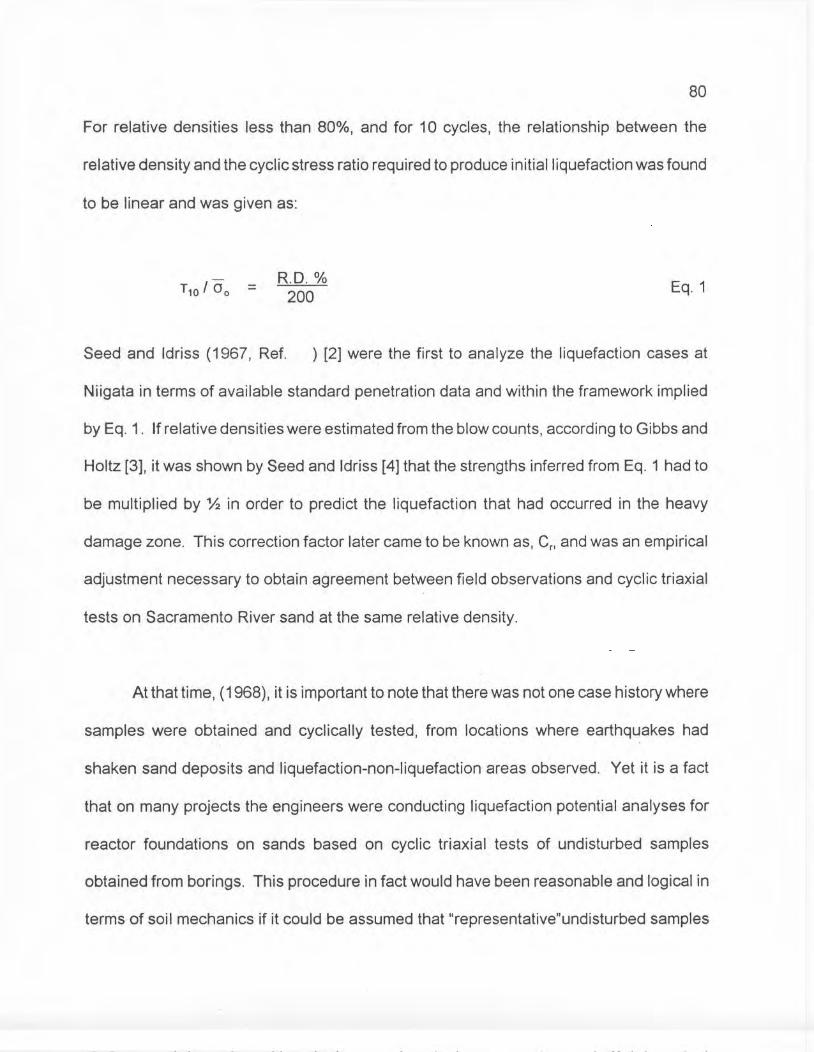
80
For relative densities less than 80%, and for 10 cycles, the relationship between the
relative density and the cyclic stress ratio required to produce initial liquefaction was found
to be linear and was given as:
T10 I 00 =R.D. %200 Eq.1
Seed and Idriss (1967, Ref. ) [2] were the first to analyze the liquefaction cases at
Niigata in terms of available standard penetration data and within the framework implied
by Eq. 1. If relative densities were estimated from the blow counts, according to Gibbs and
Holtz [3], it was shown by Seed and Idriss [4] that the strengths inferred from Eq. 1 had to
be multiplied by % in order to predict the liquefaction that had occurred in the heavy
damage zone. This correction factor later came to be known as, Cp and was an empirical
adjustment necessary to obtain agreement between field observations and cyclic triaxial
tests on Sacramento River sand at the same relative density.
At that time, (1968), it is important to note that there was not one case history where
samples were obtained and cyclically tested, from locations where earthquakes had
shaken sand deposits and liquefaction-non-liquefaction areas observed. Yet it is a fact
that on many projects the engineers were conducting liquefaction potential analyses for
reactor foundations on sands based on cyclic triaxial tests of undisturbed samples
obtained from borings. This procedure in fact would have been reasonable and logical in
terms of soil mechanics if it could be assumed that "representative"undisturbed samples
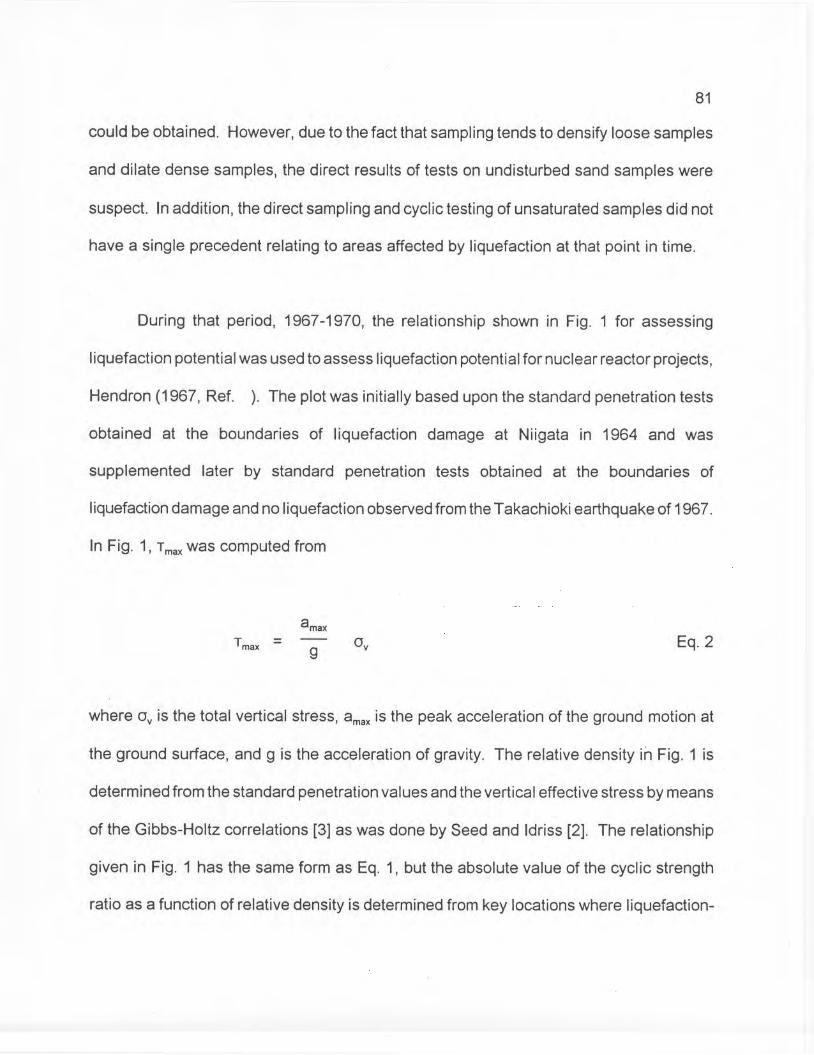
81
could be obtained. However, due to the fact that sampling tends to densify loose samples
and dilate dense samples, the direct results of tests on undisturbed sand samples were
suspect. In addition, the direct sampling and cyclic testing of unsaturated samples did not
have a single precedent relating to areas affected by liquefaction at that point in time.
During that period, 1967-1970, the relationship shown in Fig. 1 for assessing
liquefaction potential was used to assess liquefaction potential for nuclear reactor projects,
Hendron (1967, Ref. ). The plot was initially based upon the standard penetration tests
obtained at the boundaries of liquefaction damage at Niigata in 1964 and was
supplemented later by standard penetration tests obtained at the boundaries of
liquefaction damage and no liquefaction observed from the Takachioki earthquake of 1967.
In Fig. 1, T max was computed from
Tmax -
amax
g Oy Eq.2
where Oy is the total vertical stress, amax is the peak acceleration of the ground motion at
the ground surface, and g is the acceleration of gravity. The relative density in Fig. 1 is
determined from the standard penetration values and the vertical effective stress by means
of the Gibbs-Holtz correlations [3] as was done by Seed and Idriss [2]. The relationship
given in Fig. 1 has the same form as Eq. 1, but the absolute value of the cyclic strength
ratio as a function of relative density is determined from key locations where liquefaction-
82
non-liquefaction behavior was observed and where ground motion measurements made
it possible to estimate the levels of dynamic shear stresses. Although this plot was simple
and did not contain many case histories, it did provide a framework for evaluation a new
site by the use of the standard penetration test blow counts, which was the only index
property available from key locations affected by liquefaction.
The summary of standard penetration data and of field performance observations
from 35 locations by Seed and Idriss in their 1971 paper entitled "A Simplified Procedure
for Evaluating Soil Liquefaction Potential," [5], represented a significant step forward. The
heart of the simplified procedure was the use of the standard penetration test values, the
known or approximated ground accelerations, and the Gibbs-Holtz correlation to interpret
the observed behavior from the case histories.
A new site could then be evaluated from standard penetration test results, by the
"Simplified Method." The name of the "simplified" method unfortunately implied that there
was a more exact sophisticated method. This led some engineers at this time to believe
that the cyclic strength ratio of a soil in the field was most appropriately determined by
multiplying the triaxial cyclic strength ratio from tests of undisturbed samples by a Cr value
ranging from 0.55 for low relative densities to 0.68 for high relative densities.
The observation of case histories interpreted according to the simplified method
ultimately took the form shown in Fig. 2 as published by Seed, Arango, and Chan [6] and
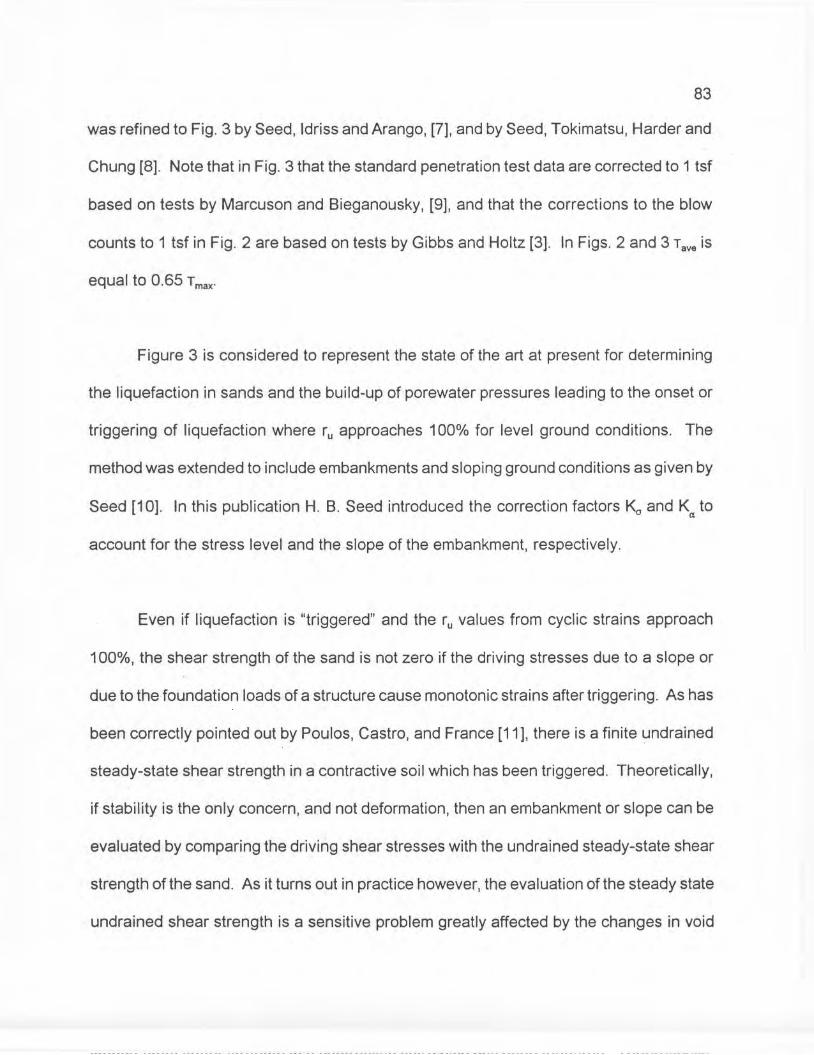
83
was refined to Fig. 3 by Seed, Idriss and Arango, [7], and by Seed, Tokimatsu, Harder and
Chung [8]. Note that in Fig. 3 that the standard penetration test data are corrected to 1 tsf
based on tests by Marcuson and Bieganousky, [9], and that the corrections to the blow
counts to 1 tsf in Fig. 2 are based on tests by Gibbs and Holtz [3]. In Figs. 2 and 3 Tave is
equal to 0.65 Tmax'
Figure 3 is considered to represent the state of the art at present for determining
the liquefaction in sands and the build-up of porewater pressures leading to the onset or
triggering of liquefaction where ru approaches 100% for level ground conditions. The
method was extended to include embankments and sloping ground conditions as given by
Seed [10]. In this publication H. B. Seed introduced the correction factors 1<0 and Ka to
account for the stress level and the slope of the embankment, respectively.
Even if liquefaction is "triggered" and the ru values from cyclic strains approach
100%, the shear strength of the sand is not zero if the driving stresses due to a slope or
due to the foundation loads of a structure cause monotonic strains after triggering. As has
been correctly pointed out by Poulos, Castro, and France [11], there is a finite undrained
steady-state shear strength in a contractive soil which has been triggered. Theoretically,
if stability is the only concern, and not deformation, then an embankment or slope can be
evaluated by comparing the driving shear stresses with the undrained steady-state shear
strength of the sand. As it turns out in practice however, the evaluation of the steady state
undrained shear strength is a sensitive problem greatly affected by the changes in void
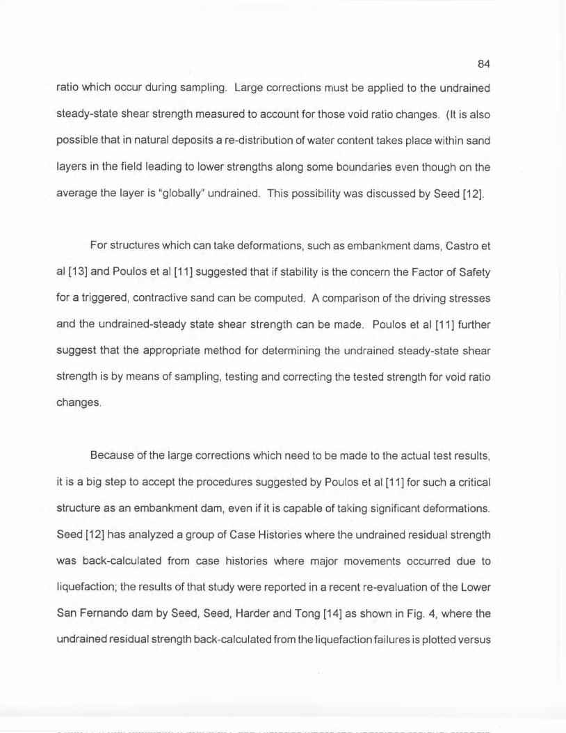
84
ratio which occur during sampling. Large corrections must be applied to the undrained
steady-state shear strength measured to account for those void ratio changes. (It is also
possible that in natural deposits a re-distribution of water content takes place within sand
layers in the field leading to lower strengths along some boundaries even though on the
average the layer is "globally" undrained. This possibility was discussed by Seed [12].
For structures which can take deformations, such as embankment dams, Castro et
al [13] and Poulos et al [11] suggested that if stability is the concern the Factor of Safety
for a triggered, contractive sand can be computed. A comparison of the driving stresses
and the undrained-steady state shear strength can be made. Poulos et al [11] further
suggest that the appropriate method for determining the undrained steady-state shear
strength is by means of sampling, testing and correcting the tested strength for void ratio
changes.
Because of the large corrections which need to be made to the actual test results,
it is a big step to accept the procedures suggested by Poulos et al [11] for such a critical
structure as an embankment dam, even if it is capable of taking significant deformations.
Seed [12] has analyzed a group of Case Histories where the undrained residual strength
was back-calculated from case histories where major movements occurred due to
liquefaction; the results of that study were reported in a recent re-evaluation of the Lower
San Fernando dam by Seed, Seed, Harder and Tong [14] as shown in Fig. 4, where the
undrained residual strength back-calculated from the liquefaction failures is plotted versus

85
N1. It should be noted that the back-calculated strengths are very low. A comparison of
the back-calculated strength and laboratory strengths from undisturbed samples corrected
to the 1971 pre-slide condition are shown in Fig. 5. The general trend is for the back
calculated strength to be lower than the strengths determined from the testing of
undisturbed samples.
Although more research may change the state of the art, it is apparent that most of
our present experience for the "triggering" of liquefaction and for the available undrained
residual strength after triggering is in terms of the standard penetration test. Professor
Seed and his co-workers have combined precedent and soil mechanics in a most
meaningful way in order to make adequate engineering judgements in these problems.
The "classical" approach in these problems is hampered by the difficulty in recovering
undisturbed representative samples of sand, a fact recognized by Terzaghi and Peck [15]
in their initial treatment of the subject of static settlement of foundations on sands.
86
Following a detailed study of embankment dam performance during earthquakes,
(Ref. 26, pg. 227), Seed observed that the seismic resistance of dams constructed of
clayey soils is much higher than that of embankments constructed of saturated sands or
other cohesionless soils. Thus for embankments which do not involve saturated
cohesionless soils, the pseudostatic method of analysis may still be used; alternatively,
methods for evaluating deformations in such dams have been developed. The computed
displacements can be compared to allowable displacements to determine the adequacy
of the embankment (See 4-7.3.d). Methods for evaluating deformations during shaking
have been developed by Seed and Newmark (Ref. 28, Ref. 29).
When embankments and/or their foundations are composed of loose sands, silts,
or gravels, the pseudostatic method may not be applicable. Therefore, analyses must be
performed to determine (a) if liquefaction potential exists and (b) whether such a liquefied
condition can lead to failure or excessive deformations of an embankment. There are
various simplified methods available for evaluating soil liquefaction potential (Ref. 29, Ref.
30, Ref. 13) based on empirical correlations between in situ behavior of sands and
standard penetration resistance.
87
4-8 References
1. U.S. Bureau of Reclamation, "Design of Small Dams," 1987.
2. U.S. Bureau of Reclamation, "Safety Evaluation of Existing Dams(SEED) Manual," 1983.
3. U.S. Army Corps of Engineers, "Earth and Rock-Fill DamsGeneral Design and Construction Considerations,"EM 1110-2-2300, 10 May 1982.
4. Terzaghi, K. and Peck, R.B., "Soil Mechanics in EngineeringPractice," 1967.
5. u.S. Army Corps of Engineers, "Seepage Control,"EM 1110-2-1901, Feb. 1952.
6. u.S. Army Corps of Engineers, "National Program of Inspect ionof Dams," Vol. 1, App. D., Recommended Guidelines for SafetyInspections of Dams.
7. U.s. Army Corps of Engineers, "Settlement Analysis,"EM 1110-2-1904, Jan. 1953.
8. u.S. Army Corps of Engineers, "Subsurface Investigations,Soils," EM 1110-2-1803, Mar. 1954.
9. u.S. Army Corps of Engineers, "Soil Sampling," EM 1110-2-1907,Mar • 31, 1972.
10. U.S. Army Corps of Engineers, "Laboratory Soils Testing,"EM 1110-2-1906, Nov. 30, 1970.
11. u.S. Army Corps of Engineers, "Engineering and DesignStability of Earth and Rock-Fill Dams," EM 1110-2-1902,Apr. 1,1970.
12. Seed, H.B. and Idriss, I.M., "Simplified Procedure forEvaluating Soil Liquefaction Potential," Journal of theSoil Mechanics and Foundations Division, ASCE, Vol. 97,No. SM9, Proc. Paper 8371, Sept. 1971, pp. 1249-1273.
13. Castro, G., "Liquefaction and Cyclic Mobility of SaturatedSands," Journal of the Geotechnical Engineering Division,ASCE, Vol. 101, No. GT6, Proc. Paper'l1388, June 1975,pp. 551-569.
~
14. Federal Coordinating Council for Science, Enginee~ing~~nd'Technology, "Improving Federal Dam Safety," July' I,- r978'~
15. Bureau of Peclamation, "Earth Manual," 1974.-"
C55
16.
17.
18.
19.
20.
21.
22.
23.
24.
25.
26.
Sherard, J.J ., V7oodward, "R.J ., Gizienski, S.F." and,Clevenger, W.A., ."Earth and Earth-Rock Dams," New York,John-,Hiley and, Sons' (1963) .
. ". " ._ • _ J. )." ; .-,
Sowers, G.B. and Sowers, G.F ., "Introductory, Soi1-Mechanicsand Foundations," New York, The Macmillan Company (1970),3rd Edi tion.
Casagrande, A., "Seepage Through Dams," Contributing toSoil Mechanics 1925-1940, Boston Society of Civil'Engineers,Boston, 1940.
Carstens, M.R. and May,G.D., "Graphs for Locating theLine of Seepage in an Earth Darn," Civil Engineering, ASCE,Aug. 1967.
Lowe, J. III, "Stability Analysis of Embankments," Journal ofthe Soil Mechanics and Foundations Division, ASCE, Vol. 93,No. SM 4, Proc. Paper 5305, July 1967, pp. 1-33.
Poulos, S. J.i et aI, "Liquefaction Evaluation Procedure,"Journal of Geotechnical Engineering, ASCE, Vol. III,No.6, June 1985.
Janbu, N., "Slope Stability Computations," Embankment DarnEngineering, Casagrande Volume, 1973.
Bishop, A.W., "The Use of the Slip Circle in the StabilityAnalysis of. Slopes," Proceedings: European Conference onStability of Earth Slopes (Stockholm) and Geotechnique,Vol. 5, No.1, 1955, pp. 7-17.
Spencer, E., "A Method of Ana1ys is,of the Stabi 1ity ofEmbankments Assuming Parallel Inter-Slice Forces,"Geotechnique,' Vol. 17, No.1, 1967, pp. 11-26.
Wright, S.G., Kulhawy, F.H. and Duncan,'J.M., "Accuracy ofEquilibrium Slope Stability Analysi!5"~1 Journal, of th~';SOilMechanics and-:Foundations'Division,,:.ASCE,· Vol-. 99,"~-:-,lO,Oct.""1973,:pp. 783:"791., ,-.-' - 'C.' ',:
•. (: !~:;_: _ ( .•• r.-: ,_-
Whitman, R.V. and Bailey, W.A., "Use of Computers for SlopeStability Analysis," Journal of the Soil Mechanics andFoundations Division, ASCE, Vol. 93, No. SM4, July 1974,pp. 475-498.
~
,,~ 27. Seed, :l-f. B. " II Cons ide rat ions ill Earthquake -Re'sist an t-:;',) Des ig£1 of: Earth -and Rockfi:1P' Dams, II- Geotechnique 29'/-
No'."3, Proc. Paper- ,5'321'" --1979,;:'pp>21S'':':263.- -. ',: -' ...'~. ;: .. '.j .-.,." - : .... ".:-,'~
28. Makdisi, F.r. ana Seed,' W.B.-, "ASitnplified; 'Procedu'refor Estimating Earth~uake-Ind~ced Deformations in Damsand EmbahkriiehI:s,·"-Re-port"EERC:':':77/19 ,"Earthqu'ake E1'1gi'neeri ngRe~~ar6h: Center, University of talif6rnia~ B~ikel~y~Aug. 1977. :
29. Newmark, N.M., "Effects of Earthquakes on Dams andEmbankments," Geotechnique 15, No.2., pp. 139-160.
30. Seed, H.B., "Soil Liquefaction and Cyclic MobilityEvaluation for Level Ground D~ring Earthquakes," Journalof the Geotechnical Engineering Division, ASCE, Vol. 105,No. GT2, Feb. 1979.
31. Castro, G.', "Liquefaction of Sands," Harvard Soil MechanicsSeries, No. 81, Jan. 1969.
32. Wisa, Anwar; Martin, E.Z.; Torrance, R.; and Garlanger,John E., "The Piezometer Probe," Proc. ASCE Conference onIn Situ Measurement of Soil Properties, Vol. 1, J~ne 1-4,1975 (Source A).
33. U.S. Army Corps of Engineers, "Earthquake Design andAnalysis For Corps of Engineers project," ER 1110-2-1806,dated 16 May 1983.
34. Leps, Thomas M., "Review of Shearing Strength of Rockfill,"Journal of the Soil Mechanics and Foundations Division,ASCE, Vol. 96, SM4, J~ly 1970, pp 1159-1170.
35. Poulos, S. J.; Robinsky, E. 1.j and Keller, T. 0.,"Liquefaction Resistance of Thickened Tailings," Jo~rnalof Geotechnical Engineering, ASCE, Vol. III, No.12, 1985.
36. U.S. Bureau of Reclamation, Design Standard No. 13,Chapter 13, April 1987.
37. TSLOPE/TSTAB-Computer Programs for Limit Equilibrium ~lopeStability Analyses, TAGA Engineering Software Services, 1984.
~.' 9
(.....It
38. Wrigh_t,. S. ,G.• , ". UTEXAS2 (Univ~r~Jty.7 ,oJ . Te.xas, .Ana)ys is, 9fSlop,es' -,":"':,v.ersion 2): A',comp'Jter Progr.amf.o.r:i Slppe·:_st,abilityCalc'Jlat ions ".•'~ ' Geotechnical' Engin.eeriJ1g:Soft~,are ,GS8,6,::-1,Geotechnical Engineering Center, Civil Engineering Department,The University of Texas at Austin, feb :1986 •
. ' ". ; '"
39. Seed, H. Bolton, "Design Problems. In, Soil' Liqy.,e~action\',JO'Jrnal of Geotechnical Enginee~ing·DivisiRn,_ASCE",Vol 113,No.8, Aug 1987.
~ /7-r;, 6e-i17
'5"fJ1/ -c;ft-1C '7~ L
~/(j
~
'10


V.LVG~Nnr33NI~N3
V-vXIGN3ddV
,"'-
(

.~
APPENDIX 4-A
F.NGINEERING DATA
Thi~ app~ndix li~ts e~gin~ering d~ta which should,be:collectedrelatihij to the d~~ign, constr~~tion, and operation of ~n embankment dam to be use~ in establishing the adequacy of e.mbankmentstructures.
1. General pro;ect Data
a. Construction dates.
b. Design of structures.
c. As-built drawings indicating plans, elevations, andsections of embankment and appurtenant structures.
d. Information on any modifications made, if applicable,such as dam raising.
2. Geotechnical Data
a. Regional and site seismicity.
h. Foundation data and geological features includinglogs or borings, geological profiles and cross sections,and reports of foundation treatment.
c. Engineering properties assigned to construction materialsand the foundation for design purposes including resultsof laboratory tests, field permeability tests, constructioncontrol tests, and assumed design properties for materials.
3. Construction History
a.
h.
c·.
d.
Construction procedures and methods used.
Properties and characteristics of construction materials.
How was quality control measured and maintained?
Final foundation and embankment reports.
~

4. Operation and ~aintenance Records--------- .. --..--.~a. Pe~formance record to date based.on instrumentation
observations and surveillance reports.
b.Comparison of conditions to which embankment has beensubjected; to those 'assumed in the original design.
c. Remedial measures undertaken during life of project.
d. Known deficiencies and any work underway to correctdeficiencies.
5. Inspection History
a. Operation inspections reports.
·b. Safety inspections reports.
_~2
'" ~~ ~-•.,•... ~ ~:Fr+~'g ~:. ,,:\iWU5j~~-

-+161,
5S'»'fr;a1rJ
4//lff5,s,t~~~
I.-,""orr>-7<>.A(jr,Jc>'t:P('(
d{~d;>-~..5-:>1<.,15r~f5(1

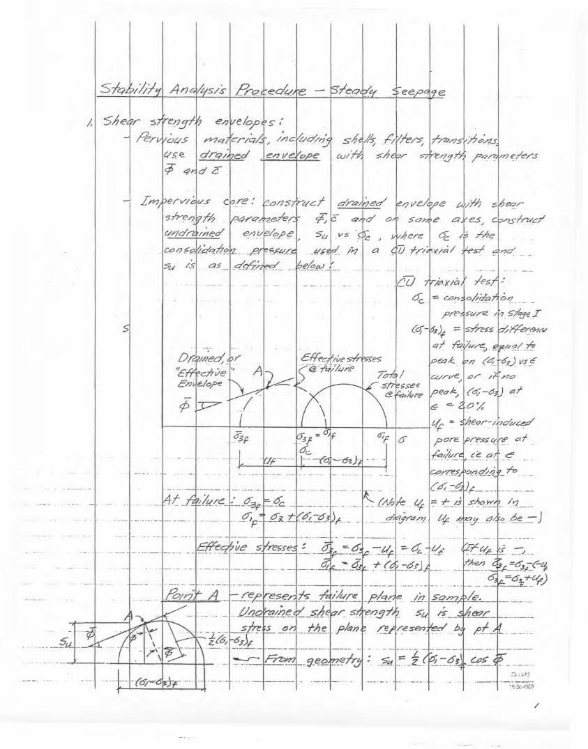
/,
.__.__?u~.._
5u I';>,.
e
CG//'I/e Or IJ' no. " .
»e~
";>'''' [,0." ", (''" -0 p "f6- = CJ h ~_~ ~ io/t'qr~/r7~~
?ore ~~~r~af,&I&.~.J_e;. ~d~.<?
: -~--[;;--L-1-~-~6~J-~~-"'-----'___1d. _ ._.z.JF?~__'_hV1 ..__ ... ."'-1"":':·
':!3·~i.:···!~{i)
/
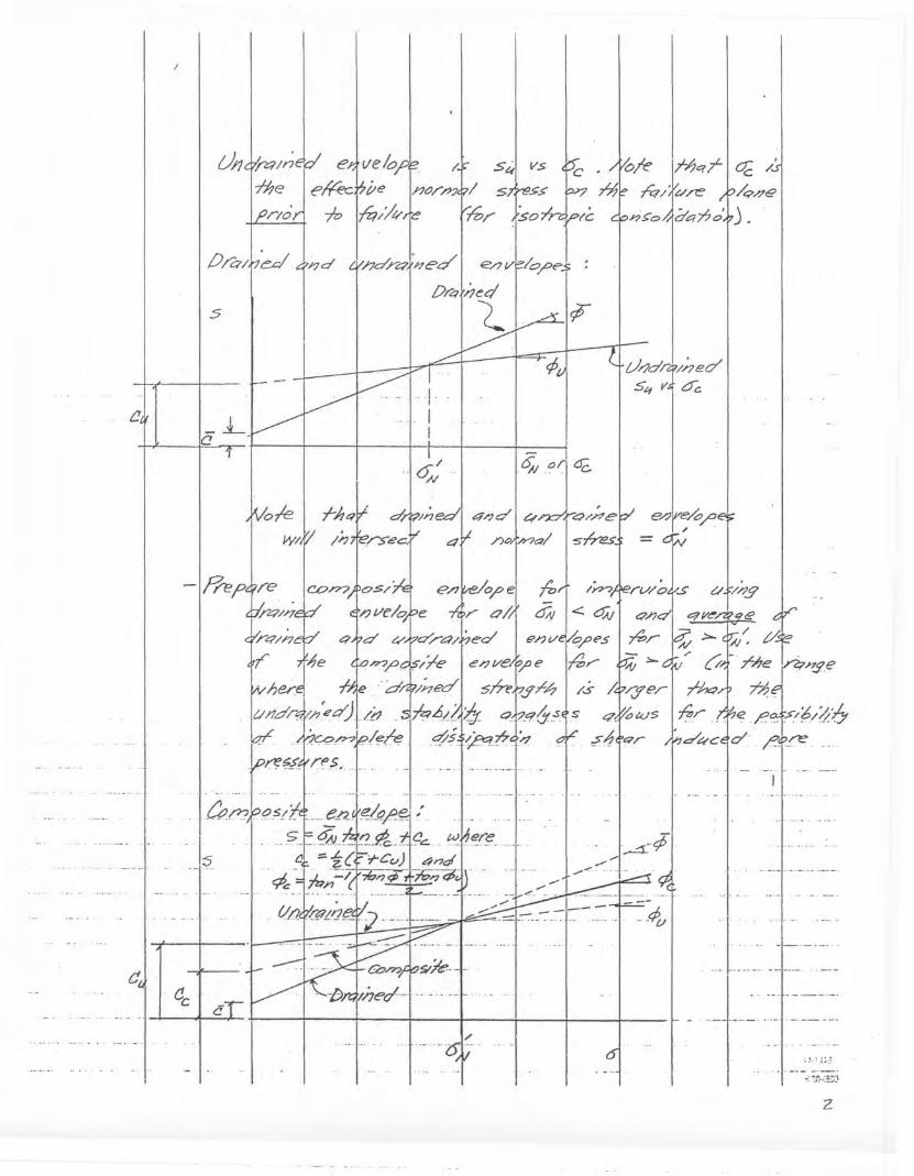
--l- - - -
........ -
.u_ .. ".__ •. _ ... __ 1 •• ._
o.¥/~g
--.;Po
T/;qT}~/..'f"q/ tY.n=' /q//e
n£"ol~Cr~o')_
U//'d~/~ed'54 V~ 0:
---
q,(/oWS
~6ft:7r
~-¢..-_/~ ..
~orl6C.
S~I vs
~nedl 4/701 c"
/--.0v-
U/1
c~
5
f)/27/,
15
C!e
c,
c.
/--_ .. _ ...~. __ .-
~.; i;.:
-:'-:'~:5:0
z
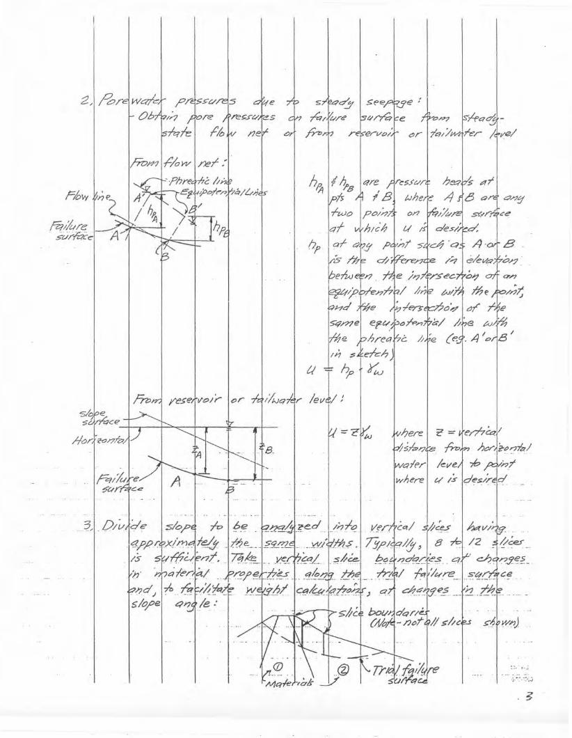
2Jrb;1
f=low
m/hre.. s-C//-/i:ic c
e
!}
tl7~
'O~ r*q~~r 17&7//Y'/4Te:r /.tvel
:";'''--:-:'':.j
z: =1em~1/;n,r );«~i'-~r7~/-,b
/15I/c.
.~~~I~v/;
hereI,.'L'/STi!2~,
'C?1e>/'
where
=CCJ/A.}
.". /evJ/}
sk>pe:S"LVtGce
.~

O'.I?1 j>~r~ 'p/"e-f54'/"e.s1 t?Cn.?J7e ~
y,1~/;e..r
o/Jdt/
arls~d6'
(;';' :i;.:
:o/tc:~_~p~J,1
M -~------- .~------..--"rPc1H_- .;;w - -ret:l~I !Jne ' pH--_.# .. H' •...•. q- - 0..SdT-
,
.-. XJ!:;:Y-_. ~r.J on.
'B
'/7
S;/ce
'A
411711'
;.:.:,:-<: .•..•.
-f
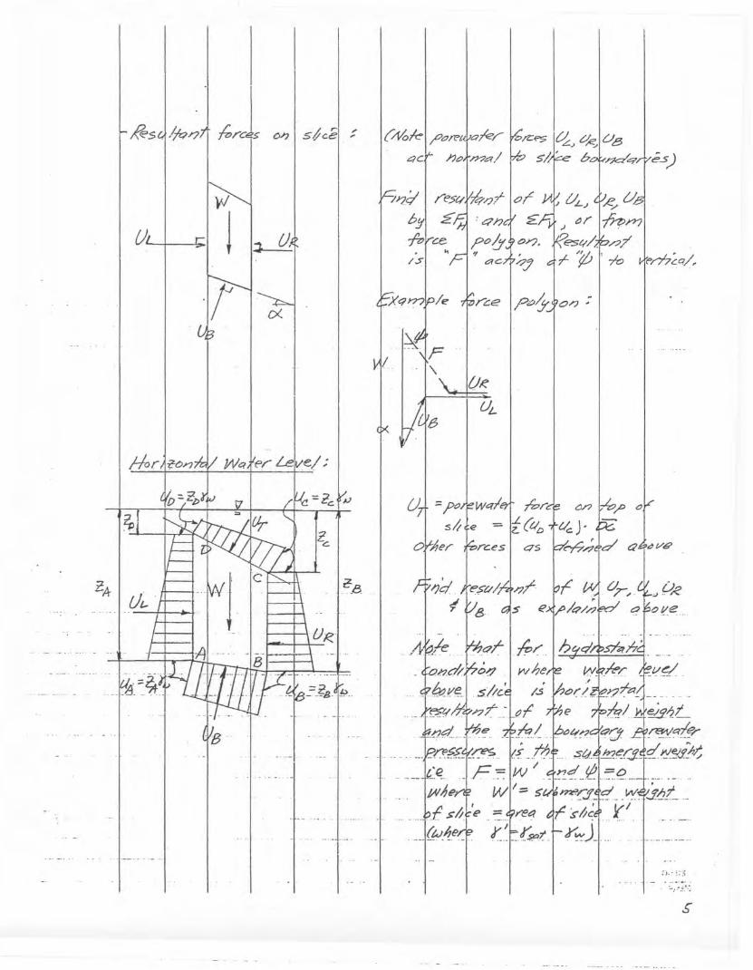
ZA
#s
?p
"/~
-·JB
J. fh
0<.
Zc.
UR
,..•.
C:/3
(~kl /,O/l"uV0k/4Cr- 17?.J/;l?a/
ne
Of?~
U'-
?~1
~~
i{tlD
O/J .•
es)
«>m~q/,
~,..- :;";;
S"
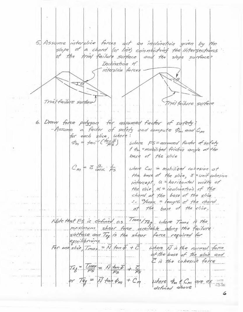
~
bY' Y4e:ec/?4>;.:zs
S<!!,r~f'"
St.l~ce':>
C.::>.qPS/LPll C7T
. 1~~r~1ciJn (,eM .d~I1r)'ec/ qk,o lie
t!.,0
Ht<Jhe,re i'=-~.>~r~~dI~~j~'<~qV&..= )??Clvi'l ~C;I frlc;fi1' on k ~T Ir-,;fp
tJr ~c· -/./c.'{!:
'.SIX
- ,.,i7 ~J;?~
c.
_ I T~:;~~H.A;~··";'¢'I' ~_,_~_- --~ .:::",-- .., Fs =1'.,
CI'YJ
6.1 D/~
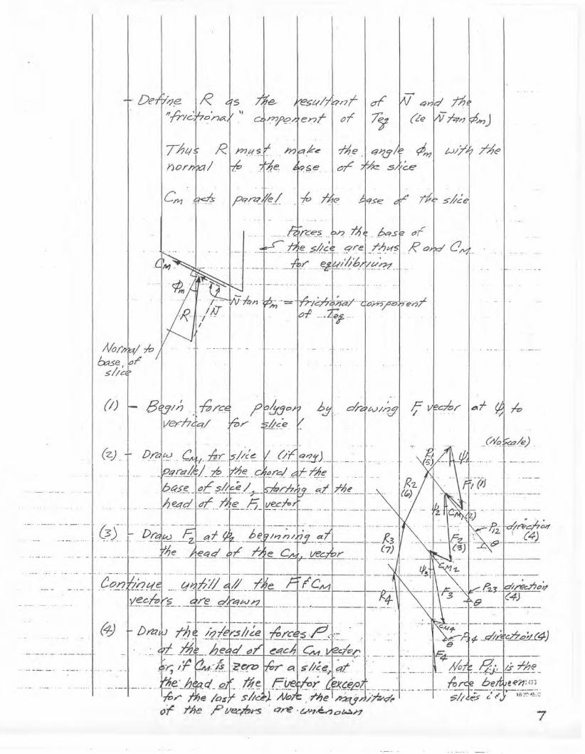
7
/4e
4~ ~(Le WmrJ
.~4- S~J'ei~- I.Ro~ (J ,_ -
bsl ar1N/-?$
-ft; ;f~<?
nT I crf'of /~
:: I:~ei'z"yl~~",""u .. J
"
R 45
en1 _,_.'u_
'De
(Z) ..
(I)
~
;{0;,
&se,5//C'
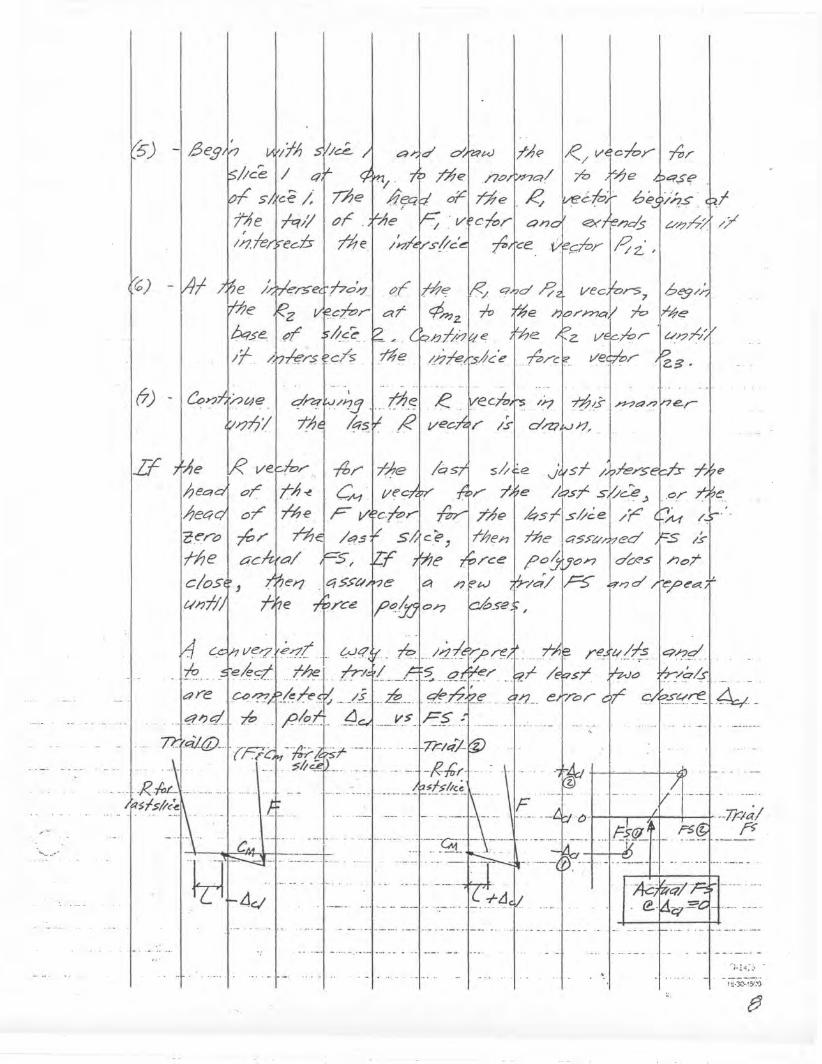
I/7
e
nTP;;~
TNe
sr~t~r~_
arld 0"1'4'.0.' I;-A~ I~/v1c~y'1-ft;".;??el /7.7~Q/ ~ t-1e e::?se
/~/Jrst/c'~?1ce.Vf~r 10z. '
.....•.• A ._. + __ -r.-~%
..__l
-- . F tr-... -'-.-.."".J-- -tA1~:1=:~~"--'~:',.-,'-:-,:.-.__~J...1 t=5(fJ,, .....' .... ~ . t t-r--'-"-"
/YJ!J .. I.~.~l. R,;q~jI R . ,.
77Je
tJr .~e
,..'Ice.
ho~d t;;/z:; --
I/c.~
ff/"$fc/5' rt;e
,,1,1
/ Cj
'ce ;;
rq//'ee-is
,- _~~~'_'. __ ._n __ ._.
~ ... ,...
•. I· ~_. --
l4c,1
cer-c>
;-I;e
C/05't ,ClI?Th
-10
f;)
5)
0) -l41
H
.... '.";/-:''': ..'1::;·3C'-:i5'.:")
fJ
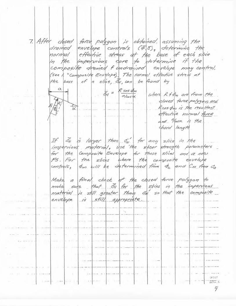
Ce?
hI
. tJS~.
.,4z,r7?lme
........ --
>tP(y.J .4.. _<1."1c1
/S.~ ~s (?ft#. .
w~e/i.
.> ec;I -Ib r-C't2
J~:~~:r~eec4~d
oJ;
iT'.Pr
.~:;//_~J,q£ecl7.!?q;r·s.6(LL __g'l'lcol'rI4~._. _
,':54
?~:~T:...r Y,../$'
ct
If'
.,
-I
:).!.-:;.::
i,j..;".·~:_ .:')
9'

lAMj""CAar'JOt}
J-pxlaiY;;;dd!;I
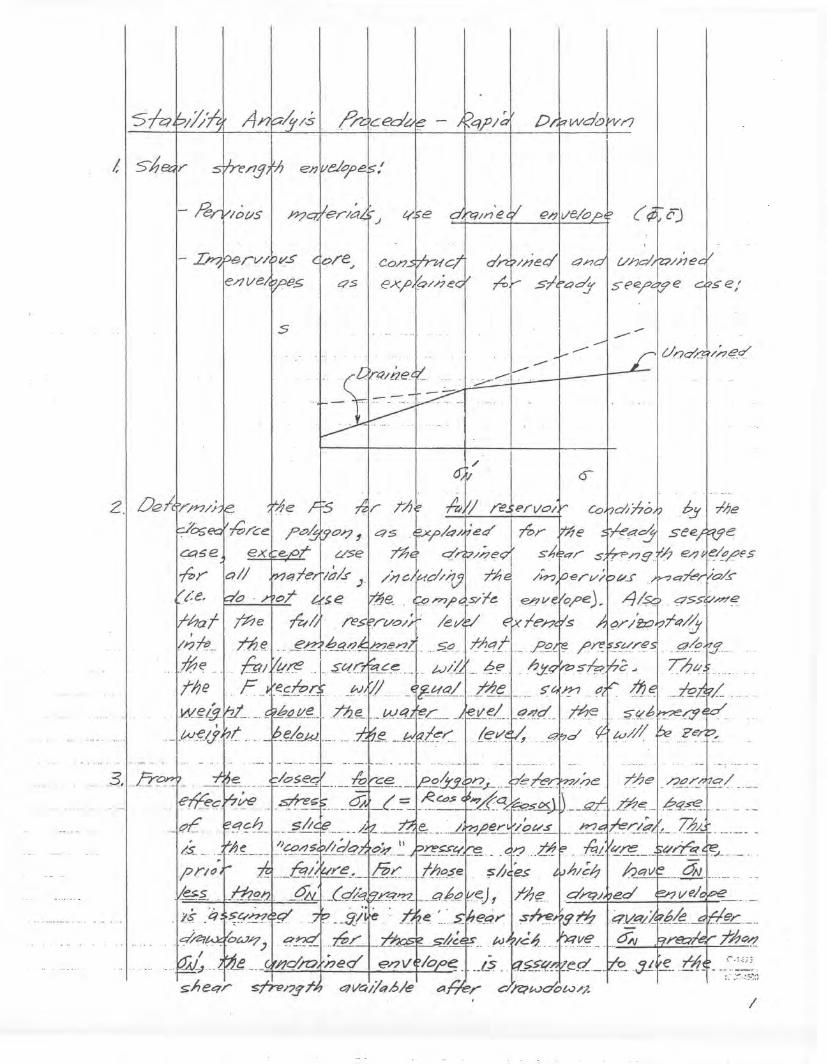
tl5'h
2.1 Oe!crrfr7/;
rv/?v.se/7~e~~e5
s
qs
-.
..;.;--::~I--
---
0-
---
/

41A~
A»4'me
w £evec,m 'S
CJT i1e
/et/e/
(Nt:f fe,
fP~
For Is/lce.
;;".
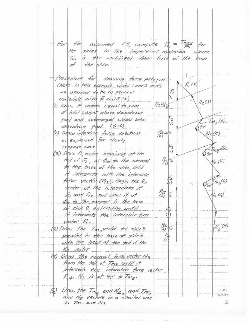
·;:;1 j-/;,rye
7;;, v.>
~
"" ~.H?.?uJre
TAr J (~/."~rwo~o,?q~~J~?" 14ec?/"
.on."
I)
/U~&·I I(1o)1 ...i
I II !
f .. I. .1. __
··IT'
'C:>.s;E'
·'-'ie--r?1._ ~ _-
~J.--/2~~-~1~·_Z=nL.. _4?lr-~ :l1:q~-c!lzm54hd /1/5 ve~~r~ /Y1 a sm?ll'q) w~.y-10 TPJ7 ~nd N2
:) ..'..;? ~:
:.3-;.t.~.;~:~
3

(r)
, CfdJ5ed/.5 H~e
q>.f~)?-?e
, r,cl /ry-
, :·,~·,,·5':1
4
~;tS)"//7-4~/...,a,,(fjr,/~(j
~{"~C;s5/([
f?hI'~¥cfl~715~n.;~~7-/-~c~:?(v;J
-f~~.'/f~,-.7",('7-1-
c,{~.'r-=>-K~'/r;r-r~wr1d:.slr(r?/?.)
-.-y-rr-~d~!'-'Irrrtrt~7:f";/"':J
7~:Y-1-1as'st/
~I?(]/(pJ0/j)~o;JIV~T¥;?-Jyb;ll
st,°11~7bJIbY='C/

0(/'rVA'lQ--:J-./f7
1/;)-1/A7{40J-':?/0jbJ~/?"~/~7 ,I-/