Embed Size (px)
Citation preview

Detection of Internal Erosion and Piping in Embankment Dams
Yu Wang1,a, Ning Guo2,b, Shijun Wang3.c and Yanchang Gu3,d 1 Nanjing Hydraulic Research Institute, Nanjing, China
2 Water Resources Department of Jiangsu Province, Nanjing, China 3 Dam Safety Management Center of the Ministry of Water Resources, Nanjing, China
a [email protected], b [email protected],c [email protected], [email protected]
Keywords: internal erosion, piping, embankment dams, monitoring system, seepage Abstract. A physical modeling was established to analyze the mechanism of initiation, continuation, and progression to form a breach for internal erosion and piping. The method accounts for the nature of the soils including sandy gravels, fine-grained sands and silty clay in the dam core and the foundation. Guidance was also provided on the detectability of internal erosion and piping by reviewing the case studies. It is shown that continuous instrumental monitoring system of seepage or surveillance would be needed to detect the internal erosion and piping.
Introduction Internal seepage failure is the erosion of soil or rock as a consequence of forces imposed by groundwater flow, and it’s a process that develops concentration of seepage flows and in time may develop large cavities that may produce embankment dam failure with a catastrophic and uncontrolled release of the reservoir (Foster and Fell, 2000). Internal erosion takes several forms, including heave, piping, concentrated leak erosion, contact erosion, and suffusion [International Commission on Large Dams (ICOLD), 2012]. The effects of these various internal erosion mechanisms have been reported to account for approximately half the dam and levee failures and incidents throughout the world (Richards and Reddy, 2007).
As noted in a detailed study of piping failures, many piping failures occur rapidly, with the majority less than 6–12 h between the first observation of a concentrated leak, and breach of the dam (Sherard et al., 1972; Charles. 1997). This has important implications for the management of dam safety, because it has been demonstrated [DeKay and McClelland. 1993; U.S. Bureau of Reclamation (USBR) 1999], that the potential for loss of life in the event of a dam failure is very dependent on the warning time available to evacuate the population at risk downstream of the dam. However, many dam owners rely heavily on surveillance, and monitoring of pore pressures and seepage to warn of potential internal erosion and piping problems for many older dams which were not provided with filters designed and constructed to control internal erosion. Many may have placed an overreliance on monitoring and surveillance rather than carrying out remedial works, given the potential for rapid failures, and the likelihood that some modes of initiation of internal erosion may not be easily detectable (Robin Fell et al., 2003). Detection may however be possible once erosion has progressed, provided the monitoring is well designed, and read frequently enough.
In this paper, a physical modeling has been conducted to analyze the mechanics of internal erosion and piping with several representative grading soil samples including the sandy gravels, fine-grained sands and silty clay. By analyzing the seepage gradient, permeability, porosity and the penetration rate, it is useful to up the process of internal erosion and piping observed in the laboratory tests into four phases—initiation and continuation of erosion, progression to form a pipe, and formation of a breach. Based on an understanding of the internal erosion and piping process and the case studies, the ability of monitoring and surveillance methods is discussed to detect internal erosion and piping for the different mechanisms of initiation of erosion. Guidance is also provided on the detectability of internal erosion and piping to give warning of possible failure, and to give time to attempt intervention to prevent the failure.
International Forum on Energy, Environment and Sustainable Development (IFEESD 2016)
© 2016. The authors - Published by Atlantis Press 114
Physical Modeling of Internal Erosion and Piping This physical modeling aims at evaluating the mechanisms associated with seepage failure process in the sandy gravel, fine-grained sand and clay, which was designed and constructed specifically for this study. The device imposes a uniform hydraulic gradient through a soil sample without converging or diverging flow conditions so that the hydraulic gradients and pressures can be easily measured through piezometric tubes and sensors, and the critical hydraulic conditions necessary to start the seepage failure process can be assessed. Natural soils and laboratory-made soils were prepared to compare various parameters of initial seepage failure process.
The primary objective of this physical modeling is to provide fundamental understanding of the phenomenon of internal erosion and piping. The gradual seepage failure process is expected to be observed through the sufficient information acquired in soil properties, sand boiling amounts, and hydraulic gradients.
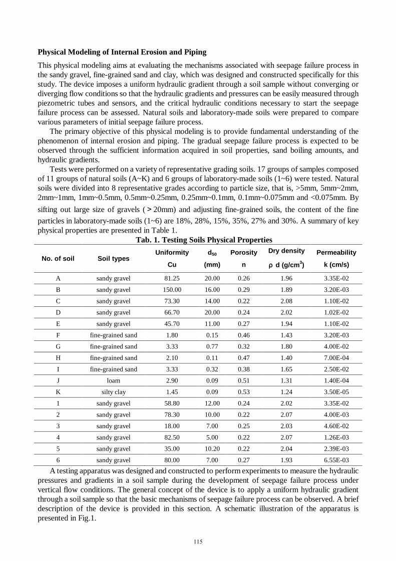
Tests were performed on a variety of representative grading soils. 17 groups of samples composed of 11 groups of natural soils (A~K) and 6 groups of laboratory-made soils (1~6) were tested. Natural soils were divided into 8 representative grades according to particle size, that is, >5mm, 5mm~2mm, 2mm~1mm, 1mm~0.5mm, 0.5mm~0.25mm, 0.25mm~0.1mm, 0.1mm~0.075mm and <0.075mm. By sifting out large size of gravels (>20mm) and adjusting fine-grained soils, the content of the fine particles in laboratory-made soils (1~6) are 18%, 28%, 15%, 35%, 27% and 30%. A summary of key physical properties are presented in Table 1.
Tab. 1. Testing Soils Physical Properties
No. of soil Soil types Uniformity
Cu
d50
(mm)
Porosity
n
Dry density
ρ d (g/cm3)
Permeability
k (cm/s)
A sandy gravel 81.25 20.00 0.26 1.96 3.35E-02
B sandy gravel 150.00 16.00 0.29 1.89 3.20E-03
C sandy gravel 73.30 14.00 0.22 2.08 1.10E-02
D sandy gravel 66.70 20.00 0.24 2.02 1.02E-02
E sandy gravel 45.70 11.00 0.27 1.94 1.10E-02
F fine-grained sand 1.80 0.15 0.46 1.43 3.20E-03
G fine-grained sand 3.33 0.77 0.32 1.80 4.00E-02
H fine-grained sand 2.10 0.11 0.47 1.40 7.00E-04
I fine-grained sand 3.33 0.32 0.38 1.65 2.50E-02
J loam 2.90 0.09 0.51 1.31 1.40E-04
K silty clay 1.45 0.09 0.53 1.24 3.50E-05
1 sandy gravel 58.80 12.00 0.24 2.02 3.35E-02
2 sandy gravel 78.30 10.00 0.22 2.07 4.00E-03
3 sandy gravel 18.00 7.00 0.25 2.03 4.60E-02
4 sandy gravel 82.50 5.00 0.22 2.07 1.26E-03
5 sandy gravel 35.00 10.20 0.22 2.04 2.39E-03
6 sandy gravel 80.00 7.00 0.27 1.93 6.55E-03
A testing apparatus was designed and constructed to perform experiments to measure the hydraulic pressures and gradients in a soil sample during the development of seepage failure process under vertical flow conditions. The general concept of the device is to apply a uniform hydraulic gradient through a soil sample so that the basic mechanisms of seepage failure process can be observed. A brief description of the device is provided in this section. A schematic illustration of the apparatus is presented in Fig.1.
115

12345678
123456789
Sensors PiezometricTubes
OverflowMouth
PorousBoard
PipeWall
SoilWaterOutlet
WaterInlet
partition
Water ValveWater Supply Pipe
ScrewPole
ElectricMotor
Transmission Systems
WaterTank
ImprovedPermeameter
Air Valve
Fig.1. Schematic illustration of testing apparatus
The apparatus is composed of an automated instrumentation and data collection system designed to make precise measurements of flow through the sample and hydraulic head at various locations within the sample. The soil sample is retained in a rigid-walled Plexiglas holder that is sealed in a porous permeable board, which is attached to a conical, stainless and influent water device. A porous permeable board at the base of the cylinder retains the soil while allowing water to flow gradually through the soil sample. The soil sample holder is a 75.0cm (height)×25.5cm (diameter) cylinder-shaped Plexiglas mold. Two rows of pore-pressure measurement ports are respectively located at the both sides of the soil sample holder, as shown in Fig.1. Nine pressure sensors (No.1~No.9) are set every 5 cm on one side of ports, and nine piezometric tubes (No.0~No.8) on the other except No.0 tube which is set in the porous permeable board to measure upstream water head. The inside of the sample holder is coated with silicone gel that serves a dual aim. First, it provides a frictional interface between the soils and the sample holder. Second, because the sandy gravels, fine-grained sand and clay indent into the silicon, it prevents a preferred seepage path along the edges of the sample that would occur as a result of larger interstitial voids caused by a lack of interlocking with the smooth Plexiglas surface.
The water pressure is flexibly controlled by the water tank attached to the screw pole to impose a uniform vertical hydraulic gradient upward through a porous permeable board into the sample. The pressure is slowly increased as two nuts arranged on the screw pole are gradually regulated. By the means of controlling the high-head in the water tank and the low-head in the overflow mouth of improved permeameter, the differential head across the sample is steadily increased until the seepage failure happens, and then the mechanical behavior of the soil is noted and video recorded.
The factors that influence the internal erosion and piping process were various, including temperature, water content and physical dimension of soil, thus the failure process test was kept constant temperature, and the soil physical dimensions were rigidly performed. All the soils were dried and prepared in the saturated condition. Soils were tested with three different specimen heights in sample holder. For sandy gravels, the filling height was generally either 30 cm or 35cm when the content of coarse sands was high and the grain size was large. For fine-grained sands, the filling height was 25cm. And for clay, the filling height was controlled less than 20cm.
There were two ways of water injection to make the sample soils gradually saturated. One was injecting water continuously to guarantee that initial gradient was less than 0.1 and increase in a small increment of 0.1, which was observed every five minutes until the hydraulic pressure was stable or
116

changed little in piezometric tubes. The other was injecting water regularly to simulate the gradually rising process, which was loaded every 15~30 minutes with a small gradient increment of 0.05~0.1.
The tests progressed until the soil completely failed. For sandy gravels and fine-grained sands, the test was not ended until soils formed the connected pathways from bottom to top and overall failure appeared. For clay, the test was not ended until clay was uplifted to float wholly. The whole gradient, permeate coefficient and overflow amount were used as the quantificational indexes.
Model results Internal erosion develops from the top and bottom of soil samples to inner part, which represents the
gradient decreases in deformation zone and the hydraulic conductivity increases. As the deformation expands gradually, the partial deformation accumulates continually. The hydraulic gradient increases to a certain value, leading to progressive soil failure. The mechanics of this progression can be explained as the soil structure with the increasing hydraulic gradient, which consist of the detachment and transport of particles.
From the experimental results, soil grain size and compactness have great impact on seepage failure process. For sandy gravels, the fine particle filled in soil plays a more important role than hydraulic conditions in the seepage failure process. However, once the seepage deformation occurs, the hydraulic gradient greatly influences process and scope of seepage failure. In addition, the geometry size of specimen impacts seepage failure process as well. The more height of the specimen, the longer it takes from bottom to top of samples when the seepage failure occurs. The mechanism of observed phenomena can be explained that seepage force imposed on the soil shear stress motivates particles movement, while sand size, gravity and friction of surrounding grains stop the particles movement. More specifically, gravity and friction of surrounding grains are the resistance of particles movement in the vertical seepage force, however, due to gravity and friction coefficient between particles on the intensity, horizontal friction has a great effect on particles movement in the horizontal seepage force. Under the condition of the same uniformity, the larger sand size , the bigger the gravity , and the stronger the critical stress. When the content of fines are constant along with the increment of soil density, the strength between the particles increases.
For fine-grained sands, under the hypothesis of ignoring the shape resistance, soil fines density represents the surrounding friction. When the content of fine particles and compactness are high, the friction plays a great role in particles. When the content of fine particles is low and grains are loose, the friction is small, thus the resistance of particles movement is mainly controlled by gravity which is related to its size. Therefore, the bigger the size, the higher the critical gradient trends to be. For silty clay, under the condition of uniformity and continuously graded aggregation, the critical gradient is high, and flow soil gets easily happened. It is nearly impossible to produce piping deformation unless the soil is non-homogeneous and discontinuously graded.
Perceptions of detection of internal erosion and piping Four phases of internal erosion and piping failure, including initiation and continuation of erosion, progression to form a pipe, and formation of a breach were identified by testing soil behavior, which have been discussed above. The four phases represent several mechanisms, and were detected quite differently. There is no obvious deformation and hard to detect this tiny change in the initiation and continuation of erosion as the gradient increases. In this phase, total deformation of soils occurs when the partial deformation expands approximately to one third of seepage path length. It’s not more evident for sandy gravels and fine-grained sands than clay. However, once internal erosion progressed to form a pipe, the partial deformation is very obvious, but not yet expanding to the whole soil. In this phase, it’s quite easy to detect the change of pore water pressure and soil stress, because the sandy soils are stable in piping process, while flow soils happen incredibly fast and are little stable with obvious deformation. Finally, destruction happens and represents the completion of the internal erosion and
117

piping process. The whole deformation occurs as the hydraulic gradient increases and all soils lose their stability.
Case studies of internal erosion and piping failures and accidents from the published literature, from sponsors and other direct sources, have been analyzed to assess the mechanisms of initiation, continuation, progression, and for failures, breach; and so far as practical, the times for each phase of the process. All failure cases available to the authors with sufficient data, and a selection of the accidents with good quality data, were used. Failures and accidents are defined according to International Commission on Large Dams (ICOLD, 1974). More details of the case studies and the references from which the data are taken are recorded (Foster and Fell, 1999; Fell et al., 2001).
Case of detection of internal erosion and piping were assessed to analyze what methods of detection were used, and how obvious it was that piping had initiated or progressed, and considering the mechanisms involved in initiation, continuation, progression and breach, and the ability of standard methods of surveillance and monitoring to detect internal erosion and piping either directly or indirectly.
From the case studies, and a general understanding of the mechanics of internal erosion and piping, it can be concluded that:
Monitoring of seepage, either by visual surveillance, or measurement, is the most common means of identifying that internal erosion and piping have occurred. It is not common to have sufficient change in the seepage, or in other factors such as pore pressure changes, or settlement, to identify conclusively that internal erosion has initiated and is continuing, which is consistent with experimental observation results. But it is more common to recognize when the erosion has progressed to the stage that a pipe has developed; or that there are changes in pore pressures, seepage, or settlement which may be related to internal erosion, but this is not conclusive and it may reflect other factors. These changes may be a precursor to a higher likelihood of internal erosion and piping, therefore it is essential that they are observed when they occur.
The inability to detect that internal erosion has been initiated relates to the common mechanisms of initiation. For piping in embankment dams’ failure, initiation is most commonly cracking, high permeability zone or hydraulic fracture, in the embankment, or around a conduit. These mechanisms could be expected to initiate very rapidly or rapidly once the reservoir level reaches the critical level at which erosion begins in cracks or high permeability zones; or the critical level at which hydraulic fracture initiates. Initiation of erosion by internal instability is likely to be a more slowly developing process, accompanied by more gradual increases in seepage, and changes in pore pressure with time.
Heave in dam foundations where seepage forces create a zero-effective stress condition is a situation which should be able to be detected readily by carefully positioned, and well monitored piezometers. Often these low effective stresses occur below lower permeability layers which act to confine the seepage flow, and it is important that piezometers are installed to measure pore pressures in these areas. These pressures are usually directly related to reservoir levels and it is important to monitor the relationship between the pore pressures and reservoir levels. Most often these conditions will occur on first filling or at historic high reservoir water levels, but we are aware of cases where pressures have increased with time possibly due to suffusion, or blockage of drains and pressure relief walls.
Failures from piping in the foundation and from the embankment to the foundation are mostly from backward erosion, or backward erosion following hydraulic fracture, blowout or heave. These would not necessarily be expected to be preceded by large increases in seepage during the time the erosion is gradually working back from the downstream exit point. When the erosion has progressed to within a short distance of the reservoir interface, it breaks through rapidly or very rapidly.
In the vast majority of cases of piping through the embankment, the reservoir was either at a historic high level, or within 1 m of the historic high level, when progression of erosion to form a pipe occurred. This is an important factor in dam safety management, and it shows that enhanced surveillance and monitoring should be carried out on dams which have potential internal erosion and piping problems, when the reservoir is at or near historic high levels. This will usually mean during
118

floods and of course on first filling. It might also be concluded that the initiation of erosion, continuation, and progression to form a pipe is less likely if the reservoir is held below its historic levels—e.g., as an interim dam safety management measure while remedial works are planned and constructed. However care should be exercised in this, since lowering the reservoir might promote drying and cracking of the core—increasing the likelihood of initiation of erosion when the reservoir level is again raised, or if a flood occurs.
Guidance of Instrumental monitoring and detection Based on the understanding of the mechanisms and detection perceptions of internal erosion and piping, some specified instrumental monitoring and detections were essentially provided to guide engineering practices. It’s commonly detected by visual inspection rather than instrumentation, or the instruments were not placed in the right place or missed the critical readings, in embankment dams at the verge of failure or under failure due to internal erosion and piping. However, after stress signs are detected or suspected installation of additional instrumentation, it is highly effective and common practice in Reclamation to monitor the performance of the embankment dams.
It appears that to detect internal erosion and piping, an instrumentation system has to be efficient and cover key areas as a typical visual inspection does. For example, a toe drain system covers large areas, and most of the times the toe drains have detected internal erosion development, but they do not give enough information of the extent and location of the internal erosion. The seepage flow collected by the toe drain system with continuous monitoring can give effective information on pH, temperature, and quantities of seepage flow, which can give useful clues to the performance of the soil and can, expand future studies on the internal erosion consequences.
An instrumentation system has to have an effective combination of instruments, and placed in areas where concentrated flows are suspected. Those areas can be located by geophysics surveys such as with an active thermal survey using fiber optics or resistivity survey according to the concerns identified by the risk analysis; both survey methods should be capable to operate with continuous readings for long periods.
To obtain detailed information of the concerns, the monitoring programs should utilize instruments with multiple purposes, and be placed in sequence of surveillance coverage, from large areas to critical areas. The instrumentation should include multipurpose piezometers, ultrasonic acoustic sensors, geophysics surveys, flow analyzers and data collection systems.
The current methodology to detect internal erosion consists of piezometers, seepage drainage systems, and geophysical methods. Embankments are monitored by piezometers, toe drains, weirs and visual inspections. However, many embankment dams had failed without early warning, because the stress signals were missed due to: instrumentation being placed in the wrong place, periodic measurements missed the critical measurement, missing measurements of soil parameters dealing with the failure type, and incomplete data regarding internal erosion cavity. Tests to predict erosion were developed in terms of indexes that vary from extremely rapid to extremely slow with their apparatus Hole Erosion Test. Briaud presents another apparatus known as Erosion Function Apparatus that measures the erosion rate (Wan, et al. 2002).
Safer performance of the embankment dams can be achieved with an effective monitoring program that includes continuous data on all the areas of concern. It implies the use of the right types and quantities of instruments within a reasonable cost. The instruments proposed here should be able to perform a long term monitoring surveillance, and their objectives include: locations of concentrated seepage flows, and measurements of pore water pressures, seepage velocities, permeability coefficient, variations of clay in suspension, and cavity surveillance, when found. The dispersible clay and the quality of the pore water content will be analyzed by water chemistry tests on the samples obtained in-situ.
Emerging technology has developed piezometers such as the BAT GMS (Groundwater Monitoring System) piezometer presented by BAT Geosystems (2007). This Bat piezometer has additional devices
119

for measurements of temperature, and permeability, and sampling seepage pore water. Knowledge of the chemistry of the water is important to predict qualitative potential for clay erodibility rates. Several BAT piezometers can be part of a BAT wireless system to monitor the ground water conditions. The use of BAT piezometers may significantly improve studies on seepage; making prediction of internal erosion more meaningful. Such improvements could lead to better remedial and preventive measures to protect the embankment performance. The improvements may consist of monitoring potential permeability variations, changes in pore water chemistry, and developing relationships such as permeability and pore water pressures that could give clues for better assessments.
Slope Indicator (2007) describes the VW (vibrating wire) piezometer which converts water pressure to a frequency signal by a diaphragm, a tensioned steel wire and an electromagnetic coil. The piezometer is designed such that a change in pressure on the diaphragm causes a change in tension on the wire. When excited by the electromagnetic coil the wire vibrates at its natural frequency. The vibration of the wire in the proximity of the magnetic coil generates a frequency signal that is transmitted to the readout device. The readout device processes the signal, applies calibration factors and displays a reading in the required engineering units. This new designed piezometer can also be installed as a multi-level VW piezometer system. Modern VW piezometers may be advantageous to measure water pressures in a multilayer foundation along a borehole; the borehole is grouted along its entire extension, and they do not need sand filters or bentonite seals for proper operation. Connections to readout devices can be made with fiber optics, eliminating the effects of lightning strikes.
Ultrasonic sensors are often used in robots to measure a cavity for obstacle avoidance, navigation and map building (2007). Ultrasonic and electromagnetic sensors, and the multiparameter sensors, are used to provide data on seepage flow and water chemistry parameters collected by the weirs. Knowledge of the cavity size will help to identify the direction of the seepage flow, and the assessment of the foundation conditions will be improved. Since erosion occurs on softer and erodible portions, the shape of the cavity may indicate branching of the cavity towards other soft zones.
There are many geophysical methods, but the active thermal survey with fiber optics and the resistivity survey are selected as the most appropriate methods to perform the initial step of the monitoring program along longitudinal sections of the embankment or cross the river valley. The main element of the active thermal survey is known as a distributed temperature sensing (DTS) device that is also known as fiber optic wire. The measurements made on this DTS are calibrated to translate the measured thermal response to flow velocity and degree of saturation. These two parameters are quite useful for a computerized seepage analysis.The benefits are permanent monitoring of the seepage flow through the downstream longitudinal section of the river valley. These longitudinal sections may include portions of the embankment as required. The intrinsic immunity to lightning strikes and other interferences that common conductors have are no longer a problem. Comparisons of seasonal variation and changes of seepage flow through the years will help to make a proper assessment of the internal erosion, and maintain a safe performance of the embankment.
The electrical resistivity method of subsurface exploration is based on measuring the resistance of the materials through which electrical current is passing (Deutsches Talsperrn Komitee,2007).The benefits of the resistivity survey are permanent monitoring of the seepage flow through the downstream side of the embankment and foundation that can be performed whenever it is needed. Comparisons of seasonal variation and changes of seepage flow through the years will help to make a proper assessment and maintain a safe performance of the embankment. It may need more time to perform the survey, but it may include improvements to more direct measurements of seepage, i.e. from existing toe drains.
Conclusions A physical modeling is established to provide fundamental understanding of the phenomenon of internal erosion and piping and analyze the mechanism of initiation, continuation, and progression to form a breach for internal erosion and piping in the embankment dams, which accounts for the nature of
120

the soils including sandy gravels, fine-grained sands and silty clay in the dam core and the foundation. The experimental results show that soil grain size and compactness have great impact on seepage failure process. Four phases of initiation and continuation of erosion, progression to form a pipe, and formation of a breach were identified by testing soil behavior. There is no obvious deformation and hard to detect this tiny change in the initiation and continuation of erosion as the gradient increases. It’s not more evident for sandy gravels and fine-grained sands than clay. However, once internal erosion progressed to form a pipe, the partial deformation is very obvious, but not yet expanding to the whole soil. In this phase, it’s quite easy to detect the change of pore water pressure and soil stress. Finally, destruction happens and represents the completion of the internal erosion and piping process.
Guidance is provided on the detectability of internal erosion and piping by reviewing the case studies. It is shown that in many dams which have poor internal erosion and seepage control and are constructed mainly of earth and rock, continuous instrumental monitoring system of seepage or surveillance would be needed to detect the internal erosion and piping. Some emerging instrumental monitoring methods are suggested to detect internal erosion, including Bat and VW piezometers, ultrasonic and electromagnetic sensors, geophysical methods of the active thermal survey with fiber optics and the resistivity survey.
Acknowledgements This work was supported by Dam Safety Management Center of Ministry of Water Resources of China and Hydraulic Engineering in Nanjing Hydraulic Research Institute. This research was also supported by the Special Fund for Public Welfare Industry of Ministry of Water Resources of China (201501033) and International S & T Cooperation Program of China (2011DFA72810). The opinions, findings and conclusions or recommendations expressed in this paper are those of the authors, and are permitted to publish from relevant research organizations and Clients.
References
[1] Charles, J A Special problems associated with earthfill dams. Proc., 19th Int. Congress on Large Dams, Florence, General Report, International Commission on Large Dams (ICOLD), Paris, Question 73, Volume 2 (1997)., pp 1083-1193.
[2] DeKay, M L, and McClelland, G H. Predicting loss of life in cases of dam failure and flash flood. Risk Anal., Volume 13 (1993), issue 2, pp 193-205.
[3] Deutsches T K. Assessment of the Risk of Internal Erosion of Water Retaining Structures: Dams, Dykes and Levees. Intermediate Report of the European Working Group of ICOLD. Contributions to the Symposium on 17-19 September 2007 in Freising, Germany (2007).
[4] Foster, M A, and Fell R. A framework for estimating the probability of failure of embankment dams by internal erosion and piping, using event tree methods. UNICIV Rep. No. R-377, School of Civil and Environmental Engineering, Univ. of New South Wales, Sydney, Australia (1999).
[5] Foster, M A, and Fell R. Use of event trees to estimate the probability of failure of embankment dams by internal erosion and piping. Proc., 20th Int. Congress on Large Dams, Beijing, International Commission on Large Dams (ICOLD), Paris, Question 76, Volume 1 (2000), pp 237–260.
[6] ICOLD (International Commission on Large Dams). Lessons from dam incidents. Committee on Failures and Accidents to Large Dams, ICLOD, Paris, France (1974).
[7] ICOLD (International Commission on Large Dams). Internal Erosion of Existing Dams, Levees, and Dikes, and their Foundations. ICOLD, Paris, France, Bulletin Preprint-164 (2012).
121

[8] Richards, K S, and Reddy K R. Critical appraisal of piping phenomena in earth dams. Bull. Eng. Geol. Environ, Volume 66, issue 4, pp 381-402 (2007).
[9] Robin F, Chi F W, et al.. Time for development of internal erosion and piping in embankment dams. Journal of Geotechnical and Geoenvironmental Engineering, Volume 129 (2003), issue 4, pp 307-308.
[10] Sherard, J L, Decker, R S, and Stryker, N L. Hydraulic fracturing in low dams of dispersive clay. Proc., Specialty Conf. on Performance of Earth and Earth Supported Structures, June 11–14, Purdue Univ., Lafayette, Ind., School of Civil Engineering, Purdue Univ., and Soil Mechanics and Foundation Div., American Society of Civil Engineers (ASCE), Volume 1 (1972), Part 1, pp 653–689.
[11] Slope Indicator www.slopeindicator.com, DGSI Multilevel VW Piezometer (2007)..
[12] U.S. Bureau of Reclamation (USBR). A procedure for estimating loss of life caused by dam failure. Publication No. D50-99-06, U.S. Bureau of Reclamation, Denver (1999).
[13] Wan, C F and Fell, R. Investigation of internal erosion and piping of soils in embankment dams by the slot erosion test and the hole erosion test, UNICIV Report No. R-412, The University of New South Wales, Sydney 2052, Australia (2002).
122